Submitted:
04 December 2025
Posted:
05 December 2025
You are already at the latest version
Abstract
The paper studied the effect of high-voltage short-pulse electrohydraulic discharge (HVSPED) on the processes of catalytic cracking of oil sludge in order to increase the yield of light hydrocarbon fractions. A set of laboratory experiments was carried out with varying the key parameters of HVSPED - voltage, pulse frequency and exposure time. A nanocomposite bentonite catalyst impregnated with nickel was used. The optimal electrophysical parameters of oil-sludge treatment by HVSPED were determined, providing the maximum yield of gasoline and kerosene fractions. The effectiveness of HVSPED treatment of oil sludge in the presence of a catalyst was confirmed by DTA–thermogravimetric analysis and chromatographic-mass spectral analysis of the light and middle fractions of the hydrogenate. The proposed approach made it possible to enhance the resource and energy efficiency of oil-sludge processing using HVSPED, demonstrating high potential for further industrial application.
Keywords:
oil sludge
; catalyst
; bentonite
; nickel
; HVSPED (high-voltage short-pulse electrohydraulic discharge)
; hydrogenation
1. Introduction
Oil production and refining enterprises, as well as oil transportation through pipelines, are accompanied by the formation of significant volumes of oil-containing waste, including oil sludge (OS). Oil sludge is formed during the production, transportation and storage of oil, and contains a significant amount of hydrocarbons that can be re-involved in processing. Oil sludge formed in the oil industry is a complex mixture, mainly containing water, organic and inorganic residues. Due to the content of pathogenic bacteria, parasites and heavy metals, they pose a danger to the environment and human health. Oil sludge contains inert solid substance. The oil industry around the world produces more than one billion tons of oil sludge annually [1].
This waste is one of the most common and environmentally hazardous forms of industrial pollution. It is estimated that there is up to 7 tons of oil sludge for each ton of oil produced. Typical oil sludge composition includes water (30-80%), petroleum products (10-50%) and solid inclusions (1-40%). The organic phase is represented by petroleum hydrocarbons (7-10%) and emulsified or dissolved compounds (5-10%) [2], and the inorganic phase is represented by silicon and iron oxides, as well as traces of aluminium, sodium and zinc [3].
Currently, the known technologies for processing oil sludge are classified into physical, mechanical, and biological methods [4].
Traditional oil sludge disposal methods, such as burial or incineration, are associated with the loss of valuable hydrocarbons and negative environmental impact. In this regard, the processing of oil sludge in order to extract marketable oil is considered as a more rational and resource-saving approach.
To date, various methods of extracting oil from oil sludge have been studied: freezing [5], solvent extraction [6], microwave irradiation [7], centrifugation [8], ultrasonic treatment [10], pyrolysis [10,11]. However, the majority of existing technologies—including thermal, biological, mechanical, chemical, and physicochemical methods—fail to provide adequate processing efficiency and environmental safety. Furthermore, their implementation relies on costly, fully imported equipment requiring specialized technical support, as well as substantial consumption of reagents (such as polyurethanes, resins, liquid glass, and cement). As a result, the overall environmental footprint of these sludge-processing approaches remains considerable.
A possible solution to the problems of reducing the negative impact of oil sludge on the environment is to extract useful components from hydrocarbon raw materials contained in oil sludge and convert them into finished commercial products while minimizing the share of waste. In recent years, oil-producing enterprises have introduced into production various technological solutions aimed at the disposal of oil production and processing waste.
However, as the results of literature analysis [1,2,3,4,5,6,7] show, there is no currently universal method of neutralization and disposal of oil sludge that meets all the requirements. Various types of centrifuges and separators, both imported and domestic, purify water, reduce the harmful effect of mechanical particles, while preserving the hydrocarbon component. These disposal methods require less costs than simply burning oil sludge, and their level of efficiency is an order of magnitude higher. Each of these technologies has its own advantages and limitations; nevertheless, the processing of oil sludge already allows obtaining several valuable products, including marketable oil, boiler fuels, and certain construction materials.
According to [12], the development of methods for processing oil sludge using mechanical, physical, and chemical techniques, followed by biological post-treatment, is environmentally safe and enables more efficient utilization of oil waste.
According to V.G. Maksimovich [13], oil sludges from the major fields of the Krasnodar Territory were analyzed. It was determined that the contents of hydrocarbons, mechanical impurities, and water in these wastes differed significantly among the fields. An increased content of manganese, nickel, vanadium, zinc in the OS of some deposits was revealed. All groups of hydrocarbons present in crude oil are also found in oil sludge; however, it should be noted that the content of light hydrocarbon fractions is lower than in the original oil, while the proportion of heavy (high-boiling) fractions is significantly higher. This correction is associated with the deposition of heavier and more viscous oil fractions together with mechanical impurities and under the influence of gravity. The properties of OS of even one species have been found to vary widely. This is due to the variety of processes that result in the formation of OS. Considering that the annual oil production is about 500 million tons annually, the mass of oil sludge formed, under various circumstances, will be equal to 30-50 million tons annually.
At present, a fundamentally new direction of scientific work has appeared in the field of natural sciences, associated with the study of the effect on a substance of such physical factors as radiation, electromagnetic radiation, ultrasound, plasma, high pressure, elevated temperature, gravity, etc., both with isolated and joint effects. The above active factors are often characterized by the conditional term "extreme chemistry".
In this work, the influence of the development nanocatalyst based on bentonite with nickel applied in the process of hydrogenation of oil sludge (Atasu-Alashanku) under a high-voltage short-pulse electrohydraulic discharge was studied.
Electromagnetic fields formed in the process of electrohydraulic discharge also have a strong effect on both the discharge itself and on the ionic processes occurring in the surrounding liquid. Under their influence, various physical changes and chemical reactions occur in the treated material, partial breaking of the bond in hydrocarbon chains with the formation of light fractions from oil sludge boiling up to 300°C, as well as other transformations of hydrocarbons, the density and viscosity of the starting material change.
Analysis of literature sources [2,3,4,5] showed that the electrohydraulic effect is most effective for oil sludge processing. The use of the electrohydraulic effect enables the extraction of gasoline and diesel fuel from oil deposits with high yield. However, in the literature [2,3,4,5] a high yield of up to 50% light fractions is achieved by mixing oil sludge with light oil, gasoline and diesel fuel. In addition, these operations involve heating the preformed mixture in the reactor from 85 to 180 °C. Applying an electrohydraulic effect with the addition of light hydrocarbons to the oil sludge can lead to an explosive situation.
According to the results of previous studies [14,15,16], it was found that the electrohydraulic effect is most effective for processing oil sludge with a high content of organic mass.
In the main scientific literature, there are no reported results on the effect of the catalyst on the process of processing oil sludge using the electrohydraulic effect. Due to the complexity of the chemical composition of oil sludge, there is no information in the literature on the possibility of optimal control of the oil sludge processing process.
This paper examines the HVSPED impact on the process of catalytic hydrogenation of oil sludge in order to increase the yield of light hydrocarbons and improve the quality characteristics of the final products. For the first time, the methodology of factor planning of the experiment was used to analyze the process, which made it possible to systematically study the effect of the key parameters of the HVSPED plant (discharge voltage interelectrode distance, capacitance of capacitor banks, exposure time and hydrogenation temperature, as well as the added nanocatalyst) on the conversion efficiency of a low molecular weight hydrocarbon compound.
The lack of data in the literature on the application of statistical methods for planning an experiment to this technology emphasizes the relevance and scientific novelty of the study. The results of chromatographic-mass spectrometric and elemental analysis confirm a significant increase in the yield of low boiling fractions under optimal processing conditions. The presented approach demonstrates the potential for improving the efficiency of oil sludge processing and can serve as the basis for further scaling and implementation in industry.
Thus, there is a need to investigate the possibilities of using HVSPED to intensify the catalytic cracking of oil sludge. This work is aimed at:
1. determination of optimal conditions for the impact of HVSPED (voltage, capacitor bank capacity, inter-electrode distance and processing time);
2. assessment of the impact of HVSPED parameters on the distribution of light, medium and heavy hydrocarbon fractions;
3. identification of the advantages of technology in comparison with traditional methods of oil sludge processing.
Paper [17] shows the effect of electrohydraulic treatment of the mixture on the composition and physicochemical properties of the obtained liquid products. It was shown that the yield of the light fraction and mixture increases under the influence of a high-voltage electrohydraulic discharge.
The purpose of this work is to determine the optimal conditions for the effect of a high-voltage short-pulse electrohydraulic discharge (HVSPED) on oil sludge in the presence of a nanocatalyst in order to intensify its thermal decomposition and increase the yield of target hydrocarbon fractions.
2. Results and Discussions
To study the effect on thermal decomposition of oil sludge containing catalyst, five samples were prepared: Sample 1 - oil sludge without added catalyst; Sample 2 - (BenNi)mixture of oil sludge with 1% nickel applied on bentonite (bentonite with particle size of 0.1 mm); Sample 3 - (BenNiB)mixture of oil sludge with 1% nickel applied on bentonite (bentonite with particle size 0.1 mm). Ben - initial bentonite, BenB - bentonite after acid leaching, BenNi - bentonite impregnated with nickel Ni solution Ni(NO3)2·6H2O, BenNiB - nickel-containing catalyst based on leached bentonite, BenNiB-HVSPED - catalyst + HVSPED treatment system for oil sludge processing.
Analysis of TG- and DTG-curves of thermal decomposition of oil sludge (Figure 1) shows that the process is characterized by several consecutive stages of mass loss. The most intense mass changes are observed in the range ≈ 200-420°C, which corresponds to the active pyrolysis of the organic component of oil sludge. The minimum on the DTG curve at 315°C indicates the temperature of the maximum decomposition rate associated with the degradation of the resinous-asphaltene components.
The Coats-Redfern integral method was used to quantify the kinetic parameters of the process. Processing of experimental data at heating rates (10 °C/min) made it possible to determine the values of the activation energy (Ea) and the pre-exponential factor (ln A) in a wide range of conversion degrees (α = 0.1-0.9).
The results obtained indicate that the activation energy of oil sludge decomposition is significantly dependent on the temperature regime. At a low heating rate of β = 10 °C/min, Ea ranges from 115-107 kJ/mol, which reflects the sequential course of both low-energy processes (evaporation and desorption) and more energy-consuming stages associated with the decay of heavy hydrocarbon fractions.
A decrease in Ea with increasing heating rate is typical for oil sludge and can be explained by the fact that rapid temperature growth leads to the overlap of individual reaction stages and a reduced influence of diffusion limitations. At the same time, lnA values show a steady increase with increasing Ea, which indicates that the kinetic parameters correspond to the Arrhenius equation and is consistent with the mechanism of complex multi-stage decomposition.
The data obtained confirm that the thermal decomposition of oil sludge is a combination of overlapping reactions, including dehydration, evaporation of light fractions, destruction of resinous-asphaltene substances and the formation of a carbonaceous residue. The activation energy values fall within the range characteristic of heavy oil residues, which is consistent with the literature data and confirms the validity of the chosen analytical methodology. The presented kinetic parameters can be used to optimize pyrolysis modes and develop energy-efficient technologies for thermal processing of oil sludge.
The given thermogravimetric curve (DTG curve in Figure 2) shows the process of decomposition of samples before (a, b/BenNi) and after (c, d/BenNiB) leaching with the catalyst.
The derivative of the thermogravimetric curve (Figure 2b), corresponding to bentonite without leaching, clearly shows two stages of decomposition. The first peak is observed at 322°C and corresponds to the removal of weakly bound organic compounds and surface components. The second peak, located at 523°C, reflects the thermal decomposition of the more stable phases associated with the catalyst. The high intensity of both peaks and 65% conversion indicate good thermal stability and strong fixation of the catalyst in the crude bentonite structure.
Figure 2 (c, d) shows the DTG curve of leached bentonite modified with the same catalyst. As in the previous case, there are two main stages of thermal decomposition, but the nature of their course is significantly different. The first peak is shifted to the left to 318°C, which indicates a weakening of surface interactions due to acid treatment. The second peak observed at 431°C shows a decrease in the heat resistance of the residual phases. The combined decrease in peak temperatures, decrease in peak intensity and decrease in conversion (~ 58%) confirm that leaching results in a decrease in the number of active sites and a decrease in their anchoring strength in the bentonite structure.
Figure 2 shows the thermogravimetric (TG/DTG/DSC) curves of the sample of mixture of oil sludge with 1% nickel applied to bentonite (bentonite with a particle size of 0.1 mm). In the first stage (up to 318°C), there is a slight endothermic weight loss associated with the removal of moisture and highly volatile components. The main decomposition step (200 to 500°C) is followed by an intensive exothermic reaction of cracking and decomposition of the organic part of the sludge. In the presence of the catalyst, the peak of the maximum decomposition rate shifts towards lower temperatures, which indicates a decrease in the activation energy of the process and an increase in catalytic activity. After 523°C, the mass stabilizes, which corresponds to the formation of a carbonaceous residue. Thus, the catalyst contributes to a deeper and more controlled thermodestructive conversion of the organic component of the oil sludge.
Figure 3 shows a graphical interpretation of the relationship betweenand 1/T calculated using the Coats-Redfern method to estimate the kinetic parameters of thermal decomposition of bentonite before (Figure 3a/ BenNi) and after (Figure 2b/BenNiB) leaching modified with a catalyst.
To select an adequate kinetic model, relationships were analyzed for various decomposition mechanisms, including reactions of the first, second and third orders, as well as the Avrami-Erofeev models (A2 and A3) and three-dimensional diffusion (Jander model). The corresponding algebraic expressions of functions f (α) and g (α) are given in Table 1.
A graphical representation of the dependence of on 1/T, based on the Coats-Redfern method, is presented in Figure 3 and allows us to determine an adequate kinetic decomposition model for the bentonite samples under study. To assess the applicability of various models, functions of the first (F1), second (F2), third order (F3), Avrami-Erofeev models (A2, A3), as well as a three-dimensional diffusion model (3D, Jander model) were considered.
Analysis of the graph (Figure 3a) corresponding to the sample before acid leaching (BenNi) shows that the experimental data best correspond to the following models: F1 (first-order reaction) shows minimal deviations in the region of high temperatures, reflecting the single-reaction nature of decomposition; A2 and A3 (Avrami-Erofeev models) are characterized by high linearity over the entire temperature range, which indicates a possible autocatalytic mechanism; On the contrary, the 3D diffusion model shows significant deviations from linearity, which indicates its low applicability and the absence of dominant diffusion control in this case.
Thermogravimetric curves (TG/DTG) showed the presence of two stages of decomposition of oil sludge and catalysts. Before acid leaching (BenNi), the process was described by first-order reactions and Avrami-Erofeev models, which indicates an even distribution of active centers. After acid treatment (BenNiB), second- and third-order models showed the best fit, indicating a complicated reaction mechanism.
Thus, thermal decomposition of untreated bentonite with a catalyst is described mainly by first-order reactions or autocatalytic mechanisms, which is probably due to the uniform distribution of active centers and a well-developed contact surface.
The graph in Figure 3b corresponding to the sample after acid leaching (BenNiB) shows a shift in the preferred kinetic model. The best approximation is achieved using second-order (F2) and third-order (F3) models. At the same time, Avrami and 3D diffusion models show more pronounced scattering of experimental data, which indicates a decrease in their applicability after chemical processing.
The change in the nature of thermal decomposition seems to be due to a change in the morphology and texture characteristics of the material as a result of acid modification. Acid leaching promotes the removal of aluminosilicate components, which changes the catalyst distribution and affects the predominant degradation mechanism.
Thus, the use of the Coats-Redfern method revealed that: before leaching, the thermal behavior of the catalyst is described mainly by models F1, A2 and A3, which indicates homogeneous and autocatalytic degradation mechanisms; after acid treatment, models F2 and F3 become preferred, which indicates a complication of the mechanism and a transition to a more heterogeneous reaction medium.
The results obtained confirm that the kinetics of thermal decomposition of the catalyst is significantly dependent on the pre-chemical treatment of the bentonite base, and the acid modification has a direct effect on the choice of an adequate kinetic model.
The Table 2 shows the activation energy (Eₐ) and pre-exponential factor (A) calculated using the Coats-Redfern method for various kinetic models applied to bentonite samples before (BenNi) and after acid leaching (BenNiB). Values are given in the form of mean ± standard deviation based on a series of calculations.
The obtained values (Table 2) and corresponding graphs (Figure 4) show that for untreated bentonite (BenNi) the activation energy and pre-exponential factor values are significantly higher across all models compared to the treated sample (BenNiB). This indicates a more energy-consuming decomposition of the phases, which is associated with a strong fixation of the catalyst and a more stable structure before acid treatment. The highest values of Ea and A are observed for models of the second (F2) and third order (F3), while the F1 model gives more moderate values and high linearity of the graphs (Figure 4). Particularly noteworthy are the extreme values of the pre-exponential factor in the case of BenNi - for example, A=(1.6±1.39)⋅10113 for F3 - which may indicate a discrepancy between this model and the real mechanism in the untreated sample. After leaching (BenNiB), there is a significant decrease in both Ea and A, which indicates a weakening of interactions, a decrease in thermal stability, as well as a change in the reaction mechanism. At the same time, models F2 and F3 show better approximations on a linear scale, while the diffusion model (3D Diff.) And Avrami models (A2, A3) lose descriptive power, which corresponds to the visual analysis of Coats-Redfern graphs.
The data presented in Table 2 and Figure 4 confirm that the kinetics of thermal decomposition of the catalyst is sensitive to acid treatment of the support; and its adequate description requires the selection of a model taking into account the structure and texture of the material.
The increased activation energies obtained by the Coats-Redfern may be related to the complex structure of humic acids containing both aromatic and aliphatic moieties differing in thermal stability. The heterogeneity of the structure leads to the fact that the thermal destruction process is described by a set of overlapping stages, each of which is characterized by its own activation energy. In addition, relatively high values may reflect the contribution of intermolecular hydrogen bonds and condensed oxygen-containing fragments, which require significant energy consumption for rupture. Similar trends were noted in the works [6,7], which confirms the correctness of the data obtained.
It was previously shown [6,7] that during the hydroconversion of tar in a mixture with bentonite, it is possible to obtain light hydrocarbon fractions suitable for the production of motor fuel components; the aqueous phase contained acetic and propionic acids, methanol and acetone. At the same time, a non-additive change in the yield of distillate products was observed, indicating the mutual influence of pine wood components and high molecular weight compounds of the heavy oil residue during their combined processing. In this paper, the effect of bentonite with a catalyst on the kinetic parameters of thermal destruction of their mixtures with oil sludge (Atasu-Alashankou) was studied by the methods of non-isothermal kinetics and dynamic thermogravimetry in order to study in more detail the detected initiating effect of the decomposition products of oil sludge (Atasu-Alashonkou).
Experiments aimed to study the effect of high-voltage electrohydraulic discharge waves on cracking of oil sludge were carried out using the method of probabilistic planning, which makes it possible to vary all factors and evaluate their effects. The optimal processing conditions were determined by the method of mathematical planning and static data processing, with the conclusion of a generalized equation using the Protodyakonov-Malyshev method. Which made it possible to study the effect of the electrophysical parameters of the HVSPED plant on the output of the target fractions [18]:
where Ymid - general average of all considered values of the generalized function;
Yp - generalized functions from factors X1, X2...;
Yi - partial function, n - number of partial function (factors);
-output of all partial functions.
The results obtained were processed using a probabilistic-deterministic experimental design (PDED) program [19]. The sequence of operations in the program boils down to finding the specific dependence of the yield of the middle fraction and the change in the viscosity of the middle fraction obtained from the oil sludge.
The yield of the fraction up to 300°C obtained from the treated oil sludge using a high-voltage short-pulse electrohydraulic discharge was selected as the criterion for evaluating the catalytic cracking of oil sludge.
The yield of fractions up to 300°C from the treated oil sludge is non-linear depending on the studied factors. (the amount of catalyst added, the capacitor capacity, the contact time, and the distance between the electrodes). In this regard, planning methods based on the Protodyakonov-Malyshev multiple correlation [20] are the most rational.
To determine the specific dependencies of the fraction yield up to 300°C from the treated oil sludge, the levels of change in the factors from the selected intervals (Table 3) and the experiment planning matrix (Table 4) were compiled.
Point graphs and approximation curves for optimizing the thermal cracking process of oil sludge are shown in Figure 5.
To verify specific dependencies, the multiple correlation coefficient R [21] and the significant correlation coefficient tR [22] were used.
High values of the correlation coefficient R and the significance of tR indicate the adequacy of the obtained dependencies. Based on the given criteria, fractions up to 300°C (y1–y4) were found to be significant for the yield.
The factors that had the greatest impact on the yield of the light fraction were the amount of catalyst added (0.5–1.0 wt%) and the distance between the electrodes (9–10 mm). In addition, factors such as capacity (0.2-0.3 μF) and exposure time (6-7 min) are also significant.
All significant individual dependencies were included in the Protodyakonov-Malyshev multifactorial equation [21,22].
Based on the individual dependencies, a generalized multifactorial equation (Protodyakonov-Malyshev) was compiled for the yield of the fraction up to 300°C from the treated oil sludge:
The Yп values calculated by the multivariate equation are given in Table 5.
The adequacy of equation (2) is confirmed by the correlation coefficient R2=0.82 and the tR value equal to 4.3. . Therefore, at R˃0.82, an adequacy test is not required, as it is met for the worst conditions.
We have determined the optimal conditions that allow us to obtain the highest fraction yield of up to 300℃ under the following conditions: the amount of catalyst added is 0.8 wt%, the capacitance of the capacitor is 0.3μFarad, the duration is 6 minutes and the distance between the electrodes is 9 mm. When carrying out experiments under optimal conditions, the yield of the given product is 29.0 wt%. The high yield of light and medium fractions (up to 29.0%) is due to the effective action of the catalyst, which contributes to the breaking of C-C bonds in heavy oil products. Nickel applied to bentonite activates hydrocracking reactions, which leads to the formation of lighter hydrocarbons. In addition, the optimum porous structure of the catalyst ensures uniform distribution of the active sites and prevents local precipitation. The nickel-supported bentonite catalyst showed high selectivity for the fraction with a boiling point of up to 300°C due to the combination of acid and metal centers responsible for the sequential splitting and stabilization of the reaction products.
We have previously experimentally found that the amount of nickel added to the support should not be less than 1.0% [23]
Table 6 shows the group and individual chemical composition of the hydrogenate of the fraction with a boiling point of up to 200℃, and Table 7 shows the group and individual chemical composition of the hydrogenate of the fraction with a boiling point of up to 300℃.
In the presence of a catalyst, a noticeable increase in the distribution of products towards medium and light hydrocarbons was observed. So, with optimal parameters of HVSPED, the yield of the light fraction was 31.8%, without the catalyst - 21.4%. This indicates the effective effect of HVSPED on oil sludge in the presence of a nickel-supported bentonite catalyst, which contributes to the high yield of the hydrogenate.
The results obtained are comparable to other studies in the field of plasma chemical and thermocatalytic processing of oil sludge. However, unlike conventional thermal methods, the proposed approach achieves high conversion rates with lower energy costs and less by-product formation.
For the first time, the initiating effect of a high-voltage short-pulse electrohydraulic discharge on the process of catalytic cracking of oil sludge was comprehensively studied. The laws of change in kinetic characteristics of oil sludge decomposition under the action of HVSPED in the presence of a catalyst were established. Optimal combinations of parameters of electrohydraulic treatment and conditions of catalytic process providing increase of cracking efficiency and yield of target hydrocarbon fractions are determined. The obtained results expand the understanding of the mechanisms of electrophysical initiation of catalytic processes for processing hydrocarbon material and can be used in developing energy-saving technologies for recycling oil sludge.
The results of the work make it possible to develop effective modes of action of a high-voltage short-pulse electrohydraulic discharge on the process of catalytic cracking of oil sludge, which ensures an increase in the degree of its processing and an increase in the yield of light and medium hydrocarbon fractions. The proposed approach reduces the process energy consumption, optimizes catalyst consumption and reduces the volume of hard-to-recover oil wastes.
The obtained data can be used in creating energy-saving and environmentally safe technologies for processing oil sludge, as well as in modernizing installations for deep processing of hydrocarbon raw materials. The novelty of the work lies in the identification of optimal parameters of short-pulse HVSPED in combination with catalytic cracking of oil sludge in the presence of a catalyst.
Thus, the results obtained demonstrate the possibility of targeted process control by varying the parameters under study. The use of equation (16) makes it possible not only to assess the influence of each factor but also to identify the conditions that ensure the maximum yield of the target fraction, thereby confirming its practical significance for optimizing the technological process.
4. Materials and Methods
The object of study is oil sludge obtained during oil transportation through the Kaztransoil pipeline (Atasu–Alashankou section, Kazakhstan). Its physical and chemical characteristics are given in Table 8:
The mineral resource base of bentonite clays of the Republic of Kazakhstan has a huge reserve and has the ability to significantly increase its efficiency in oil refining. Bentonite clays are widely used in various industries, such as oil and gas, mining, construction, and chemical. Due to the specific structure and properties of the surface, bentonite has high acidity and molecular sieving activity, which makes it possible to efficiently process solid and heavy hydrocarbon raw materials, which ensures a high yield of low molecular weight products [24]. In addition, bentonites with a high modular ratio have high thermal stability, which makes it possible to process heavy oil feedstocks at high temperatures. The application of nickel to bentonite improves its catalytic properties, especially in processes involving the hydrogenation, cracking, reduction and dehydrogenation of hydrocarbons [5,6]. In addition, nickel can enhance the stability of the catalyst at high temperatures and under aggressive conditions, since during an HVSPED discharge the temperature in the interelectrode gap can reach up to 10 000 °C within 10⁻⁶ minutes.
Bentonite with nickel wet impregnation method was used as catalyst. Physical and chemical characteristics of bentonite: SiO2-61.3; Al2O3-13.0; Fe2O3-3.9; CaO-0.4; MgO -3.2; Na2O -0.3; K2O -0.3. Thermal, acid and mechanical treatment was used to activate bentonite. The physicochemical characterization of the catalyst was investigated by BET (Table 9).
The specific surfaces of the samples by BET and STSA methods, as well as the pore volume using nitrogen as adsorbate gas, were determined using a Sorbtometer-M device manufactured by Katakon CJSC (Russia). (Table 6)
The specific surfaces of the nanocatalyst samples were determined using BET and STSA methods, and the pore volume using nitrogen as adsorbate gas was determined using a Sorbtometer-M device manufactured by Katakon CJSC (Russia).
The sample weight was 0.5367 g. The catalyst (BentoniteNi 1%) weighed 0.5476 g before drying; the moisture and volatile content amounted to 2 wt% of the initial sample. Drying was carried out at 200 °C for 3 hours on the lip of a beaker. The sample was then heated in the instrument for 45 minutes at 217 °C.
Peak: Maximum First Signal (normalized) = 0.138 in the “Current Measurement” mode, while in the “Chart Recorder” mode the detector signal was (4100 – 2350) = 1750 units, and then returned to zero.
During desorption, the temperature increased to +17 °C.
At P/P₀ = 0.15, the Signal (normalized) = 0.151 in the “Current Measurement” mode, and in the “Chart Recorder” mode the detector signal was (5260 – 3700) = 1560 units, and then returned to zero.
Table 9 shows the specific surfaces of bentonite.
The phase composition of the nickel-supported bentonite catalyst was examined by X-ray phase analysis. The sample was examined using a XRD-7000 X-ray diffractometer (Shimatdzu, Japan), anode: Cu, radiation wavelength Kα(Cu)=1,5406 Å, measurement range 10-50° in 2θ, measurement speed 30°/min. Figure 6 shows a diffractogram of bentonite with nickel applied.
Figure 6 shows the results of a nickel-coated bentonite diffractogram. According to the diffractogram, reflexes were measured in the range: 2θ = 10-50°. Peaks: ~ 20-22° (weak peak) - characteristic of the amorphous component of clay minerals (mixed-layer phases, amorphous SiO₂). ~26,5°- a strong peak corresponding to quartz (SiO₂). ~ 27-29° - peaks typical of montmorillonite and feldspars. ~ 34-36° and ~ 39-42° - less pronounced, probably associated with the aluminosilicate matrix. In the region of 43-45° - possible reflexes that can be attributed to nickel oxide (NiO) or metallic Ni. Intense peaks at 26-27° and 29° → quartz + montmorillonite. Table 10 shows the phase composition of the nickel-supported bentonite catalyst. The main phase is montmorillonite (the main mineral of bentonite). Impurities - quartz (SiO₂), feldspars. Nickel - weak NiO/Ni peaks are fixed in the structure at 43-45°. In this way, the catalyst is a polycrystalline material based on an aluminosilicate matrix (montmorillonite) containing quartz and fixed nickel particles in the form of an oxide (NiO) and/or metallic Ni.
It is assumed that the effect of HVSPED on oil sludge with the added catalyst bentonite containing nickel leads to the generation of active radical particles (H, •OH, O•) capable of reducing metal oxides containing bentonite and impounded nickel. From literary sources [25], the actions of HVSPED are realized by a complex mechanism, which includes partial in situ reduction of Ni2⁺ ions to metallic nickel (Ni⁰) under pulsed discharge conditions, which is confirmed by the results obtained in Figure 6 and Table 10. Together, these processes lead to an increase in the catalytic activity of the system due to an increase in the proportion of available active centers of Ni⁰ and modification of oxygen-containing groups on the surface of the support.
The preparation of the binary catalyst was carried out as follows [26]: The initial bentonite was previously ground. Then 0.1 mm samples were taken by sieve analysis. Leaching of the initial bentonite was performed using a 20% hydrochloric acid solution to remove alkali and alkaline earth metals. The catalyst was prepared by wet impregnation of leached bentonite with a 1% solution of Ni(NO3)2·6H2O. Impregnated with bentonite nitrate solutions (20 g) was kept in an oven for 2 hours, at a temperature of 80-90°C, and then further dried at a temperature of 105°C also for 2 hours. Then, the obtained catalyst samples were calcined in a muffle furnace at a temperature of 650°C for 2 hours (supported catalyst).
A thermogravimetric study was performed using a Labsys Evo TG-DTA/DSC 1600 derivatograph (Setaram, France) in corundum crucibles at 30 to 600℃ in an argon stream (shielding and purge gas flow rates of 20 and 50 ml/min, respectively). Kinetic parameter measurement results are processed using the "OriginLab" and "Anaconda3" software packages.
Experimental thermogravimetric data (TG/DTG) presented in Figure 1 were processed using the method proposed by Coats- Redfern [27,28]. The calculations were based on the Arrhenius equation (1), which describes the temperature dependence of the reaction rate constant, as well as on the formal kinetic equation (2):
where, n – reaction order, m – current sample mass, mx - mass corresponding to the end of the reaction, A - pre-exponential factor, E – activation energy, R − universal gas constant.
When the mass is reached, the reaction stops, and
0. The relative change in mass is given by:
where m0 - initial sample mass.
Given a constant heating rate:
can be written:
Integrating equation (5), we obtain:
After replacing the variable and changing the integration limits accordingly, the expression takes the form:
Enter the designation:
which allows rewriting (7) as:
To approximate the integral P(x), asymptotic decomposition is used, according to the Coats-Redfern method. Assuming 2RT≪E, we get an approximate expression:
Substituting in (9), we get:
Take the logarithm of both parts:
or expanded:
This equation has the form of a linear relationship between and 1/T, which allows to determine the activation energy by the slope of the line:
and at the intersection with the ordinate axis, calculate the pre-exponential factor A:
Experiments on the impact of HVSPED on oil sludge were carried out on a specially developed laboratory installation that allows varying the voltage, frequency and duration of the impact pulses (Figure 7-8).
A laboratory bench (the block diagram is shown in Figure 7) was designed and assembled to conduct experiments on the treatment of the investigated oil product using HVSPED. The design of the installation allows conducting experiments in a wide range of changes in the characteristics of the electric discharge.
The designed stand is located in two shielded rooms, where the main units and components are installed. The working room contains the pulse voltage generator, the controlled arrester with its ignition unit, and the processing reactor with the test sample. The auxiliary room houses the HVSPED control units, as well as the instrumentation units, which include several electronic oscilloscopes. The shielding of the rooms was implemented to eliminate the influence of electromagnetic interference generated during the HVSPED process on the instrumentation signals.
After applying a control voltage from 100 to 150 V, the generator generates high-voltage pulses of a given energy voltage, which are transmitted through the controlled arrester VE and high-voltage lines to the electrode system of the thermal reactor RO with the object of study.
The homogeneity of the electric field in the working section is ensured by a pulse voltage generator, which is assembled on a step-up high-voltage transformer with a transformation ratio of m = 200, with a maximum voltage of up to 50 kV and is designed for a current of 100 mA at the nominal operating mode. The main part of the pulse generator are capacitors after a certain period of time equal to the charging time, the capacitor battery is fully charged, and at this stage the generator is ready to transfer the stored energy to the controlled discharger and then to the electrodes of the working section, and at the same time the electrohydraulic discharge in the liquid medium under study passes 10-6 microns/sec. In the oil sludge environment, during 5 to 8 minutes of HVSPED treatment, the temperature does not change significantly from the initial temperature to 150С. The initial oil sludge temperature prior to treatment was 30-350С.
The uniformity of the electric field in the reactor was ensured due to the symmetrical arrangement of the electrodes and the uniform gap between them (5 ± 0.2 mm). The electrodes were made of stainless steel with a polished surface, which reduced the likelihood of local field concentration. To prevent local overheating, a pulsed discharge mode was used with a pulse duration of 50-100 μs and a frequency of 100 Hz, which contributed to the uniform distribution of energy in the volume of the reaction zone. The temperature was controlled by a thermocouple located near the cathode and did not exceed 800С throughout the process.
The working area is a thermal reactor, shown in Figure 8.
Two measuring electrodes are installed on the thermal reactor. The negative electrode is fixed, and the positive electrode was fixed on a micrometric screw to adjust the distance between the positive and negative electrodes.
Thermal reactor has hermetically sealed cover with sealing rubber gasket. The positive electrode is insulated with a high-strength dielectric material and pressed into the cover of the thermal reactor, connected by high-voltage cables to the controlled discharger of the HVSPED installation. Oil sludge in the amount of 150 ml to 500 ml can be treated in the developed high-pressure thermal reactor.
The role of the negative polarity electrode is played by a metal rod attached to the inner bottom of the container, the body of which by means of grounding buses is electrically connected to the negative polarity pole of the generator. Distance between electrodes - the working discharge gap can be changed by screwing the positive and negative electrodes. The height of rod 2 is selected to ensure that the working spark gap is positioned at the geometric center of the test specimen.
Electric discharges and shock waves occur in the suspension of the processed petroleum product, which ensure a change in physical and chemical characteristics. Voltage and current sensors send corresponding signals to recording equipment. Feed frequency and number of pulses are carried out in controlled arrester. Ignition unit operation is controlled and synchronized by pulses generated by delayed pulse generator.
Dynamics of power consumption and power of HVSPED unit are given in Table 11.
The presented data on the dynamics of energy consumption and the power of the HVSPED unit showed that increasing the treatment time from 5 to 8 minutes results in a discharge frequency of 300 to 1000 pulses. This treatment interval enables the HVSPED impact on oil sludge in the presence of the catalyst to achieve a maximum yield of light and medium fractions of 29–30%. At the same time, the power consumption of the HVSPED unit ranged from 60 to 96 W.
After processing the oil sludge using HVSPED, the obtained products were divided into gaseous, liquid and solid products. The liquid phase (hydrogenate) was fractionated into a light phase up to 200℃ and a medium fraction of 200-300 ℃. The individual composition of the fraction is set to determine the distribution of light (C5-C12), medium (C13-C20) and heavy (>C20) hydrocarbons. The individual light and medium fraction chemistry was performed on an Agilent 7890A gas chromatograph with an Agilent 5975C mass selective detector.
The analysis was performed under the following conditions:
column type - Rtx-100DHA
column length - 30 m;
column diameter - 0.25 mm;
column adsorbent thickness - 0.5 µm
evaporator temperature - 280 °С; column temperature - 60-300 °С;
column heating rate - 8 °C/min;
ion source temperature - 230 °С;
quadrupole condenser temperature - 150 °С;
EI+= 70 eV
carrier gas - helium A grade;
column gas pressure - 2 psi;
sample volume - 0.2 µL;
Input mode - split 20:1
mass spectrum recording mode - scan;
library - NIST 08;
analysis time - 32 minutes
The compounding percentage was calculated automatically using the GS-MSDDataAnalysis program, based on the peak areas of the total ion chromatogram, identification was carried out by mass spectra and retention times using the NIST 08 library.
5. Conclusions
Using a probabilistic-deterministic method of experimental design, a mathematical model of catalytic cracking of treated oil sludge using HVSPED was obtained.
It was established that the impact of HVSPED leads to the intensification of the cracking process due to more efficient destruction of hydrocarbon molecules and improvement of phase interaction between oil sludge components and the catalyst. The optimal exposure parameters (voltage, frequency, treatment duration) were established, ensuring maximum yield of light hydrocarbon fractions and minimization of solid residue. The experiment proved that combining HVSPED and catalytic effect provides a more thorough conversion of heavy hydrocarbons into light fractions compared to traditional thermal cracking. The results obtained confirm the prospects of combining HVSPED in the catalytic cracking process as a method of treating oil sludge, which reduces the environmental impact and increases the efficiency of disposal processes.
1. For the first time, the effect of HVSPED on the process of catalytic cracking of oil sludge was comprehensively studied.
2. The optimal conditions of exposure (voltage, frequency, pulse duration, amount of catalyst) were determined, providing the maximum yield of light hydrocarbons.
3. A synergistic effect has been established between electrohydraulic action and catalytic activation.
4. The obtained results can be used in the development of energy-saving and environmentally friendly technologies for oil sludge processing.
5. The results obtained indicate that an increase in the treatment time of oil sludge with HVSPED in the presence of a catalyst in the range from 5 to 8 minutes is accompanied by an increase in the number of pulse discharges from about 300 to 1000 shots. This treatment interval is optimal, since it provides the most intensive impact on oil sludge (Atasu-Alashonkou) in the presence of a catalyst and contributes to the formation of a maximum yield of light and medium fractions from the hydrogenate at the level of 29-30%. At the same time, the power consumption of the HVSPED unit remained relatively low and was in the range of 60-96 W, which confirms the energy efficiency of the process.
6. Based on theoretical and experimental studies, it was established that high-voltage short-pulse electrohydraulic discharge (HVSPED) has a multifactorial effect on the processes of processing oil sludge and their cracking products. Optimum processing conditions are determined by the magnitude of the operating voltage, the number of discharge pulses, the composition of the system being processed, and the use of catalysts.
7. An increase in the operating voltage (X4, the distance between the electrodes) contributes to the intensification of cracking processes and an increase in the yield of light fractions (gasoline and diesel), which is associated with deeper destruction of heavy hydrocarbons and the formation of light components.
8. Electrohydraulic treatment of the oil sludge mixture with the addition of a catalyst (bentonite/nickel) is the most economically feasible, as it allows to increase the total distillate yield to 31.8% at temperatures of 200-300°C.
9. Mixtures of oil sludge in the presence of a bentonite catalyst with nickel, the yield of the diesel fraction increases to 37.2%, which confirms the synergistic effect of the combined applicarion of HVSPED and catalysis.
10. It has been experimentally shown that the use of HVSPED provides controlled destruction of complex hydrocarbon systems and related organic compounds, as well as contributes to the formation of nanosized carbon and metal particles with high potential for catalytic systems
11. Optimal conditions for the catalytic cracking of a mixture of oil sludge with a bentonite catalyst under HVSPED, which make it possible to obtain the highest yield of the fraction up to 300℃: the amount of catalyst added is 0.8 wt%, the capacitance of the condenser is 0.3 μFarada, the duration is 6 minutes and the distance between the electrodes is 9 mm. If the given conditions are met, the yield of the specified product is 29.0 wt%, under which it is possible to significantly increase the yield of light fractions and increase the economic efficiency of the oil sludge processing process.
12. Most technologies such as thermal, biological, mechanical, chemical, physicochemical do not provide sufficient efficiency and environmental friendliness of oil sludge processing. In addition, it is distinguished by expensive 100% imported equipment, which requires qualified maintenance, the cost of reagents (polyurethanes, resins, liquid glass, cement), the environmental load of the sludge processing process is quite high.
13. Studies have confirmed the possibility of using HVSPED to activate the nickel-containing catalyst and intensify the oil sludge processing process. It has been shown that treatment under conditions of high-voltage pulse discharge contributes to a change in the structure and distribution of active centers, which affects the catalytic properties of the system.
Abbreviations
HVSPED - high-voltage short-pulse electrohydraulic discharge; PDED- probabilistic-deterministic experimental design.
Author Contributions
Conceptualization, A.S.; methodology, A.S.; software, R.S., M-F.Y.; validation, A.S., S.T., M.B., M-F. Y.; formal analysis, R.S., M.B., M-F.Y., G.S., B.Zh., G.A.; investigation, S.T., M.B. M-F.Y., G.S., B.Zh., G.A.; resources, A.S.; data curation, A.S., M.B., R.S. M-F.Y., G.S., B.Zh., G.A.; writing—original draft preparation, S.T.; writing—review and editing, S.T.; visualization, S.T., G.S., G.A; supervision, A.S., S.T.; project administration, A.S., S.T.; funding acquisition, A.S.. All authors have read and agreed to the published version of the manuscript.
Funding
This research was funded by the Ministry of Science and Higher Education of the Republic of Kazakhstan grant number AP23483556 “Processing of oil sludge in the presence of a nanocomposite catalyst into a low molecular weight compound using HVSPED”.
Acknowledgments
no applicable
Conflicts of Interest
The authors declare no conflicts of interest.
Abbreviations
The following abbreviations are used in this manuscript:
| HVSPED | High-voltage short-pulse electrohydraulic discharge |
References
- Hu, G.J.; Li, J.B.; Zeng, G.M. Recent development in the treatment of oily sludge from petroleum industry: A review. J. Hazard. Mater. 2013, 261, 470–490. [Google Scholar] [CrossRef] [PubMed]
- Mazlova, E.A.; Meshcheryakov, C.B. Problems of oil sludge utilization and methods of their processing; Publishing House “Noosphere”: St. Petersburg, Russia, 2001. [Google Scholar]
- Shornikova, E.A. Some possible ways to dispose of drilling and oil production waste; Hyphen: Surgut, Russia, 2002. [Google Scholar]
- Kalimullin, A.A.; Volochkov, N.S.; Ferdman, V.M. Landfills for the disposal of oil sludge are a solution to the environmental problems of oil workers. Environ. Ind. Saf. 2003, 6, 104–105. [Google Scholar]
- Lin, C.; He, G.; Li, X.; Peng, L.; Dong, C.; Gu, S.; Xiao, G. Freeze/thaw induced demulsification of water-in-oil emulsions with loosely packed droplets. Sep. Purif. Technol. 2007, 56, 175–183. [Google Scholar] [CrossRef]
- Al-Zahrani, S.M.; Putra, M.D. Used lubricating oil regeneration by various solvent extraction techniques. J. Ind. Eng. Chem. 2013, 19, 536–539. [Google Scholar] [CrossRef]
- Fortuny, M.; Oliveira, C.B.Z.; Melo, R.L.F.V.; Nele, M.; Coutinho, R.C.C.; Santos, A.F. Effect of salinity, temperature, water content, and pH on the microwave demulsification of crude oil emulsions. Energy Fuels 2007, 21, 1358–1364. [Google Scholar] [CrossRef]
- Cambiella, A.; Benito, J.M.; Pazos, C.; Coca, J. Centrifugal separation efficiency in the treatment of waste emulsified oils. Chem. Eng. Res. Des. 2006, 84, 69–76. [Google Scholar] [CrossRef]
- Xu, N.; Wang, W.; Han, P.; Lu, X. Effects of ultrasound on oily sludge deoiling. J. Hazard. Mater. 2009, 171, 914–917. [Google Scholar] [CrossRef] [PubMed]
- Shishkin, Y.L. Fractional and component analysis of crude oils by the method of dynamic microdistillation – differential scanning calorimetry coupled with thermogravimetry. Thermochim. Acta 2006, 441, 162–167. [Google Scholar] [CrossRef]
- Chen, J.B.; Mu, L.; Jiang, B.; Yin, H.; Song, X.; Li, A. TG/DSC-FTIR and Py-GC investigation on pyrolysis characteristics of petrochemical wastewater sludge. Bioresour. Technol. 2015, 192, 1–10. [Google Scholar] [CrossRef] [PubMed]
- Ermakov, V.V.; Sukhonosova, A.N.; Bykov, D.E.; Pirozhkov, D.A. Determination of oil sludge hazard class. Ecology and Industry of Russia 2008, 7, 14–15. [Google Scholar]
- Maksimovich, V.G. Neutralization of oil sludge and cleaning of the oil field of the Krasnodar Territory. abstract of the dissertation for the degree of candidate of technical sciences, Kuban State University, Krasnodar, 05 December 2013; p. 23 pp. [Google Scholar]
- Bodykov, D.U.; Abdikarimov, M.S.; Mirtalipov, R.T.; Aliev, E.T.; Salakhov, R.Kh.; Mansurov, Z.A. Method for Processing Oil Sludge. Patent for Utility Model No. 1729, 30 September 2016. [Google Scholar]
- Bodykov, D.U.; Abdikarimov, M.S.; Mansurov, Z.A. Processing of Oil Sludge Using the Yutkin Electrohydraulic Effect. Combustion and Plasma Chemistry 2015, 13, 303–311. [Google Scholar]
- Bodykov, D.U.; Abdikarimov, M.S.; Mansurov, Z.A; Nazhipkyzy, N. Sludge processing using electrohydraulic effect. Carbon", USA, 2016. [Google Scholar]
- Zhukova, Y.M.; Chernychevsy. Impact of high-voltage electrohydraulic discharge on physical and chemical properties of oil and petroleum products. Dissertation for the degree of candidate of chemical sciences, Saratov State University named after N.G. Chernychevsy, Saratov, 2008. [Google Scholar]
- Satybaldin, A.; Tusipkhan, A.; Seitzhan, R.; Tyanakh, S.; Baikenova, G.; Karabekova, D.; Baikenov, M. Determination of optimal conditions for processing oil bottom sediments using electrohydraulic effect. East.-Eur. J. Enterp. Technol. 2021, 5, 30–38. [Google Scholar] [CrossRef]
- Belyaev, S.V.; Malyshev, V.P. Ways of development of probabilistic planning of the experiment. In Integrated Processing of Mineral Raw Materials of Kazakhstan; Science: Almaty, Kazakhstan, 2008. [Google Scholar]
- Malyshev, V.P.; Katkeeva, G.L.; Zubrina, Y.S.; Oskembekov, I.M.; Gizatullina, D.R. Development of a comprehensive probabilistic model of grinding and flotation processes. Complex Use Miner. Raw Mater. 2017, 1, 47–53. [Google Scholar]
- Tyanakh, S.; Baikenov, M.I.; Yun, M.F.; Khamitova, T.O.; Karimova, A.B. Kinetics of oil sludge thermolysis process in presence of nickel, cobalt and iron-supported microsilicate. Pol. J. Chem. Technol. 2023, 3, 101–109. [Google Scholar] [CrossRef]
- Malyshev, V.P. Probabilistic-deterministic planning of the experiment; Science: Almaty, Kazakhstan, 1994. [Google Scholar]
- Baikenov, M.; Izbastenova, D.; Zhang, Y.; Su, X.; Balpanova, N.; Tusipkhan, A.; Akanova, Z.; Moldabayev, A.; Tulebaeva, B.; Taurbaeva, G. The Catalytic Hydrogenation of Phenanthrene: The Impact of Chrysotile and Coal Shale Catalysts. Fuels 2025, 6, 47. [Google Scholar] [CrossRef]
- Baikenov, M.I. Catalytic Hydrogenation of Coal and Heavy Oil. Doctoral Dissertation, Institute of Organic Synthesis and Coal Chemistry, Ministry of Education and Science, Academy of Sciences of the Republic of Kazakhstan, Almaty–Karaganda, Kazakhstan, 1999; p. 268 pp. [Google Scholar]
- Zhukov, L.A.; Yutkin, L.A. Electrohydraulic Effect and Its Application in Industry; Book on Demand: Moscow, Russia, 2024; p. 253 pp. [Google Scholar]
- Tyanakh, S.; Baikenov, M.I.; Yun, M.F.; Fomin, V.N.; Baikenova, G.G.; Ashimhanov, A.S.; Seitzhan, R.S. Determination of optimal conditions for catalytic hydrogenation of oil sludge (Atasu–Alashankou). Eurasian J. Chem. 2023, 28, 139–146. [Google Scholar] [CrossRef]
- Coats, A.W.; Redfern, J.P. Kinetic Parameters from Thermogravimetric Data. Nature 1964, 201, 68–69. [Google Scholar] [CrossRef]
- Vyazovkin, S.; Burnham, A.K.; Criado, J.M.; Pérez-Maqueda, L.A.; Popescu, C.; Sbirrazzuoli, N. ICTAC Kinetics Committee Recommendations for Performing Kinetic Computations on Thermal Analysis Data. Thermochim. Acta 2011, 520(1–2), 1–19. [Google Scholar] [CrossRef]
Figure 1.
TG and DTG curves of thermal decomposition of oil sludge (a and b).
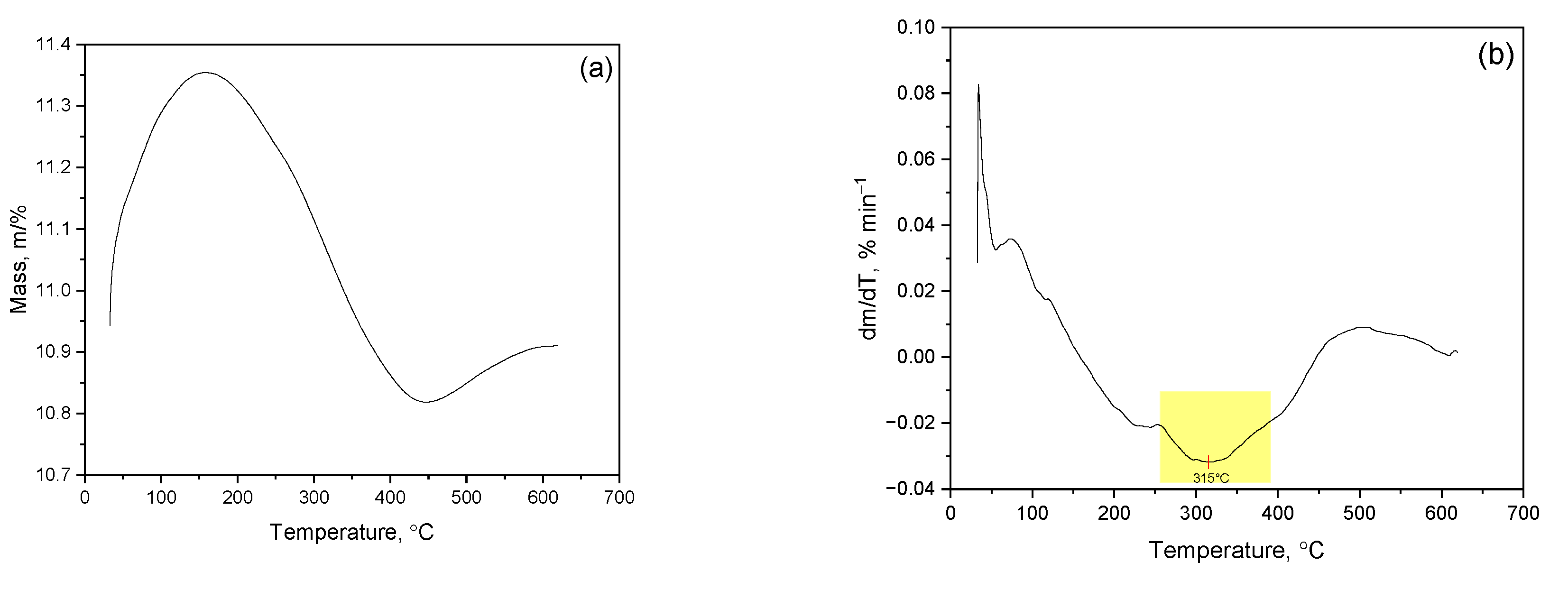
Figure 2.
TG- and DTG-curves of thermal decomposition of bentonite before (a, b/BenNi) and after (c, d/BenNiB) leaching with catalyst.
Figure 2.
TG- and DTG-curves of thermal decomposition of bentonite before (a, b/BenNi) and after (c, d/BenNiB) leaching with catalyst.
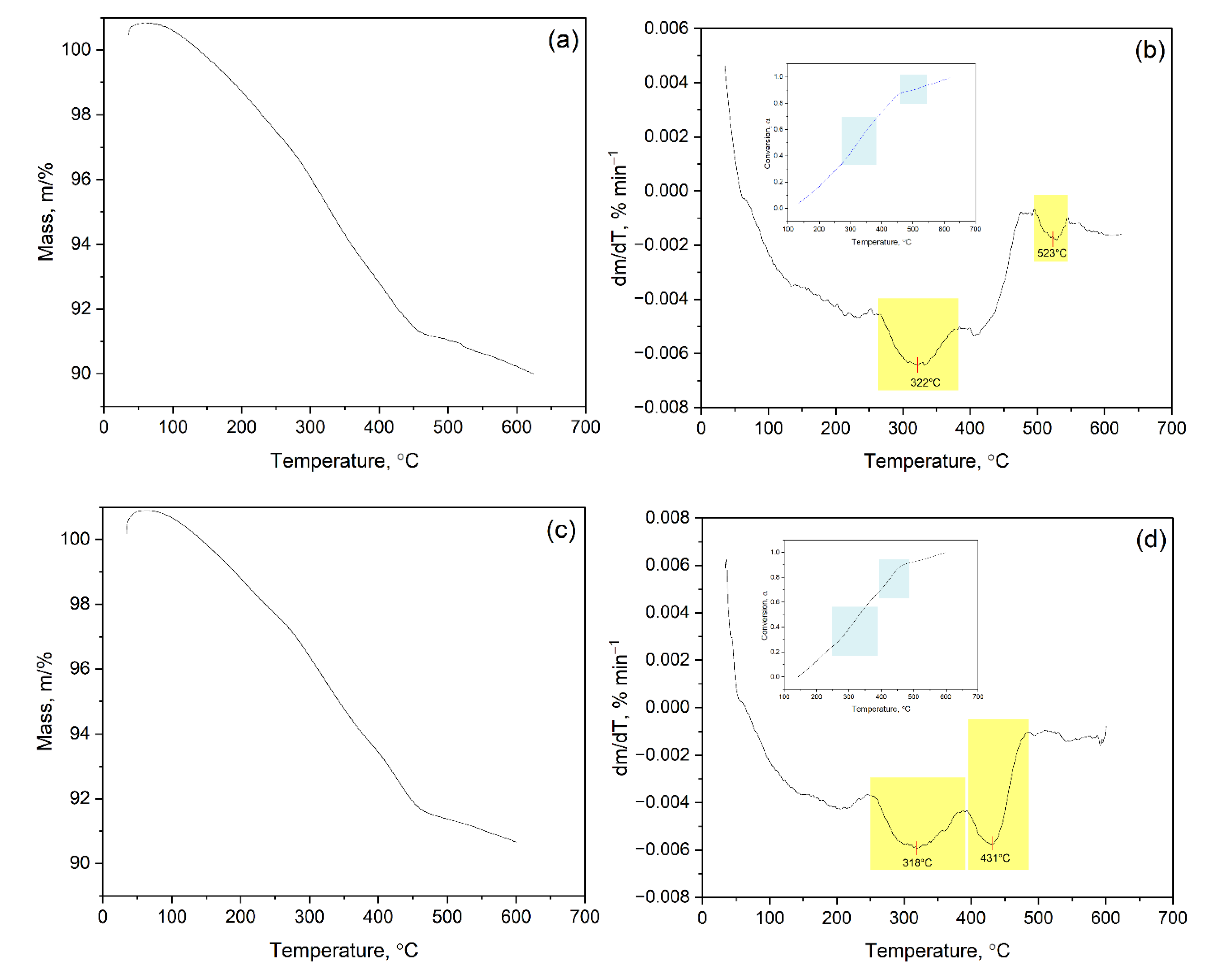
Figure 3.
Graphical representation of the dependence of lng(α)/T2g(α)/T2 on 1/T, calculated using the Coats–Redfern method, for the decomposition of bentonite before (a, b / BenNi) and after (c, d / BenNiB) leaching with the catalyst.
Figure 3.
Graphical representation of the dependence of lng(α)/T2g(α)/T2 on 1/T, calculated using the Coats–Redfern method, for the decomposition of bentonite before (a, b / BenNi) and after (c, d / BenNiB) leaching with the catalyst.
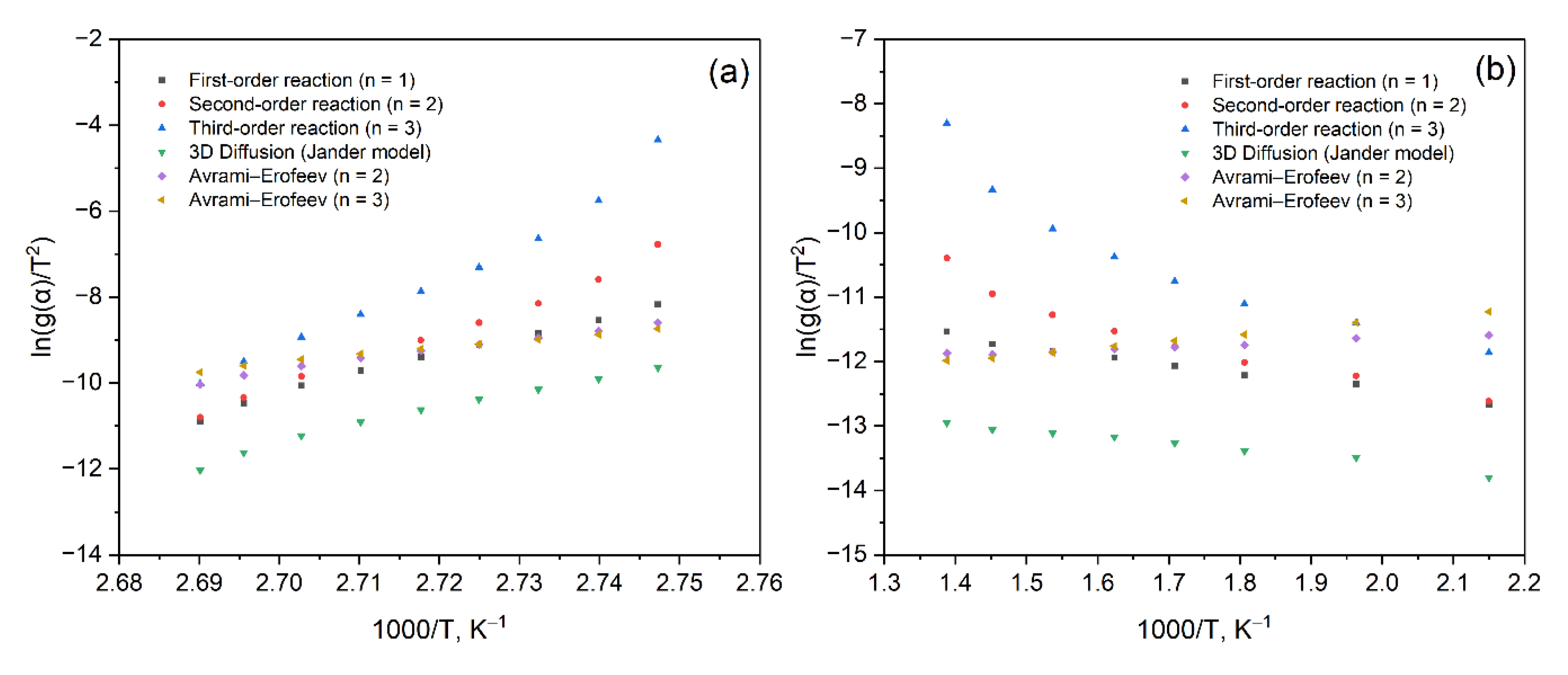
Figure 4.
Activation energies and calculation errors for various kinetic models applied to thermal decomposition of bentonite decomposition before (a, b/BenNi) and after (c, d/BenNiB) leaching with catalyst.
Figure 4.
Activation energies and calculation errors for various kinetic models applied to thermal decomposition of bentonite decomposition before (a, b/BenNi) and after (c, d/BenNiB) leaching with catalyst.
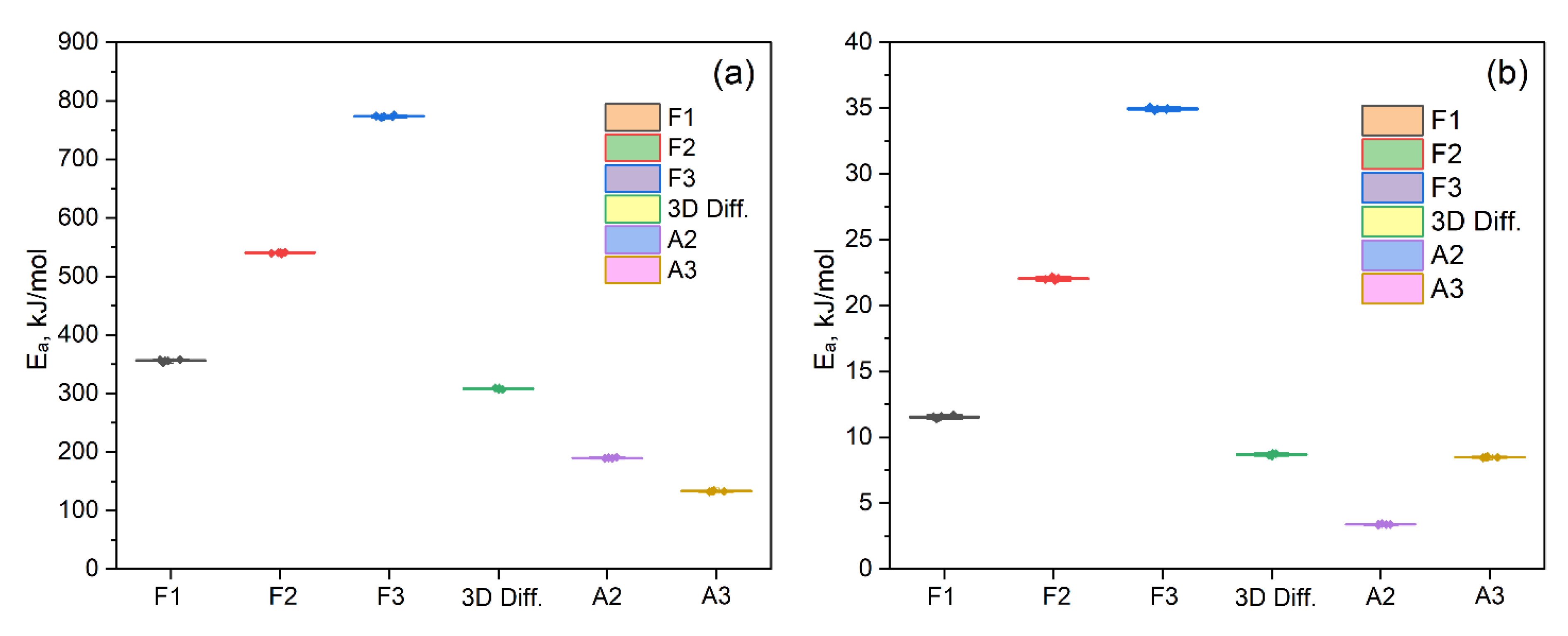
Figure 5.
Individual dependence of fraction yield up to 300℃ from treated oil sludge.
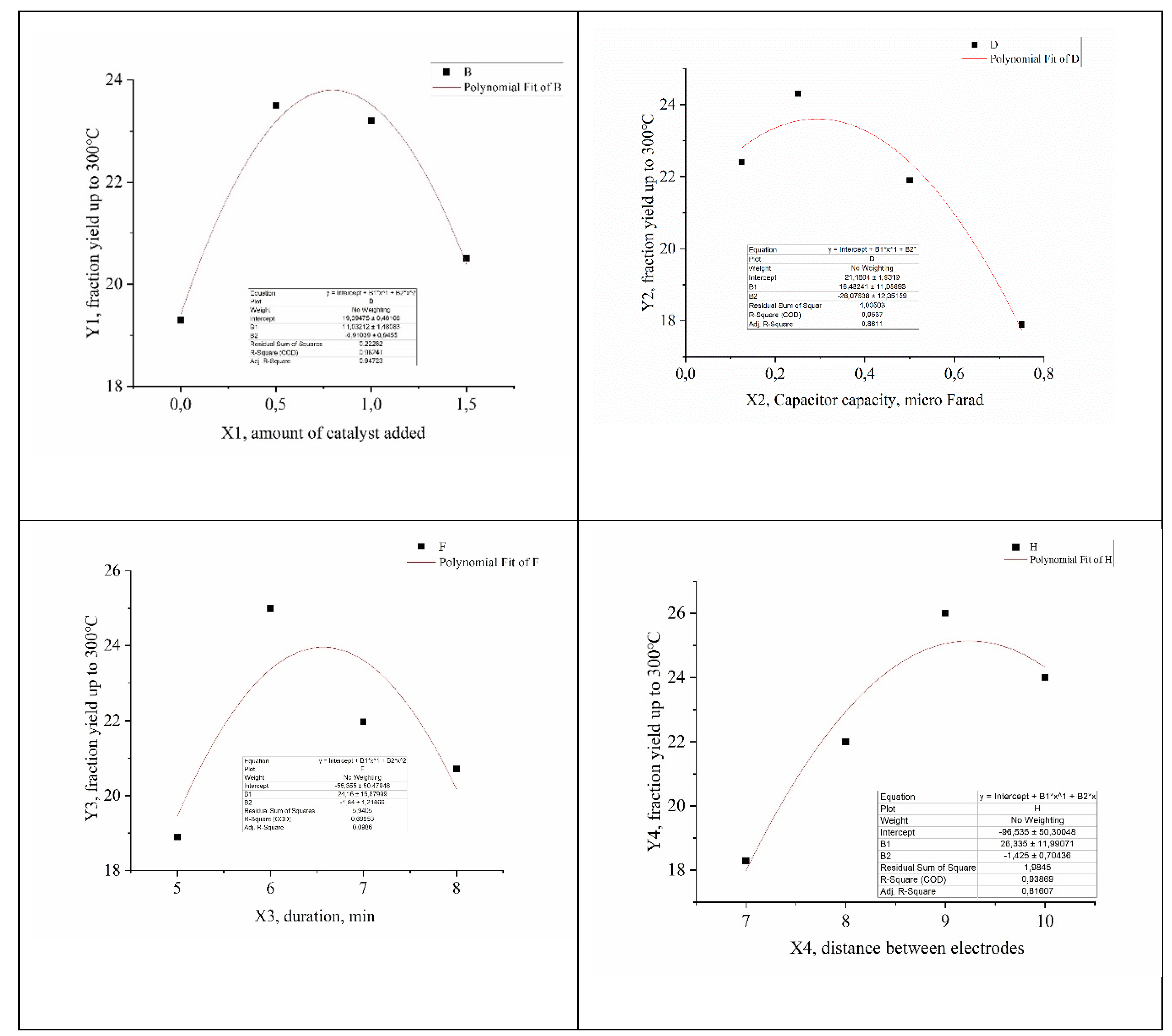
Figure 6.
Diffractogram of bentonite with nickel applied (phase composition).
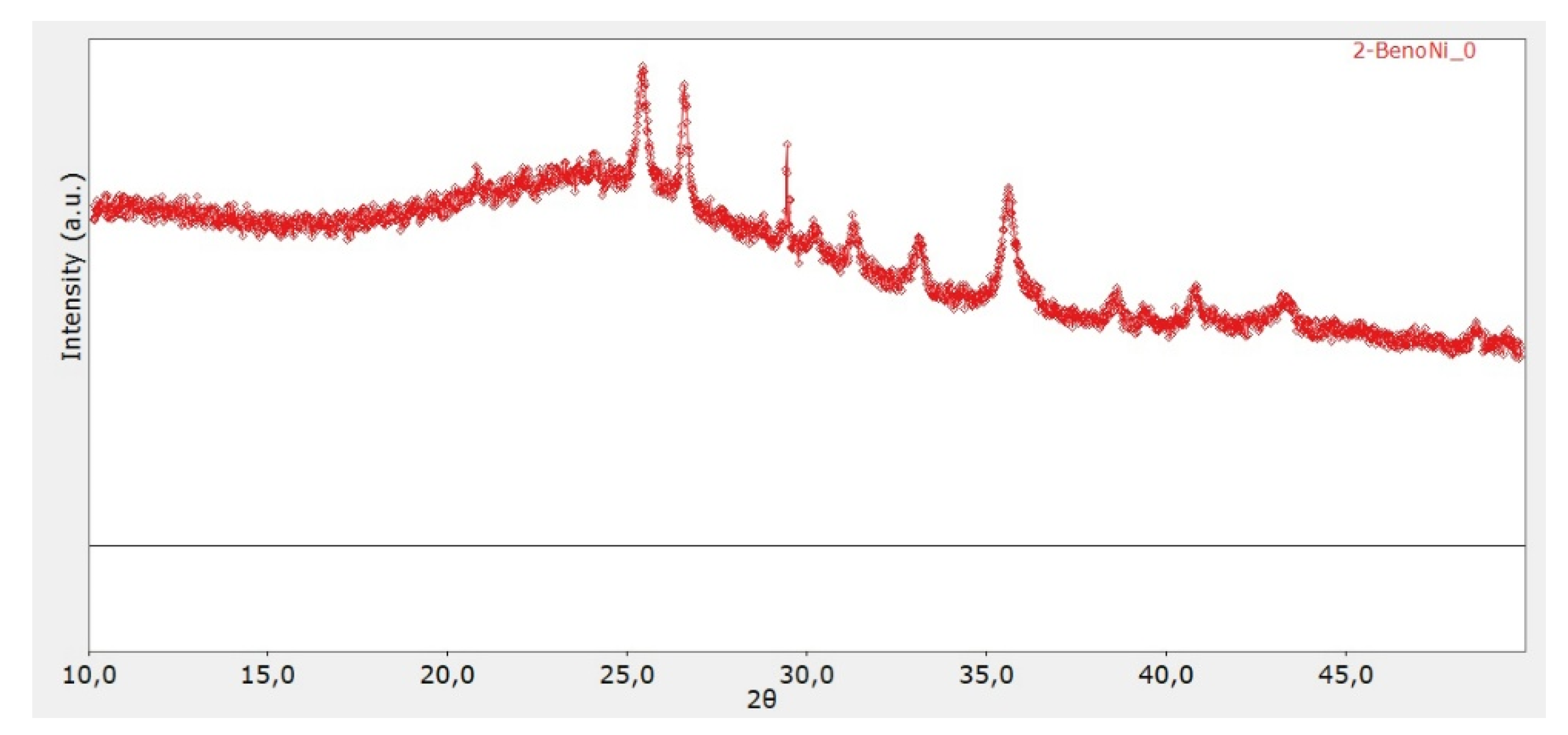
Figure 7.
Diagram of the creation of electrohydraulic shocks with a single forming gap.
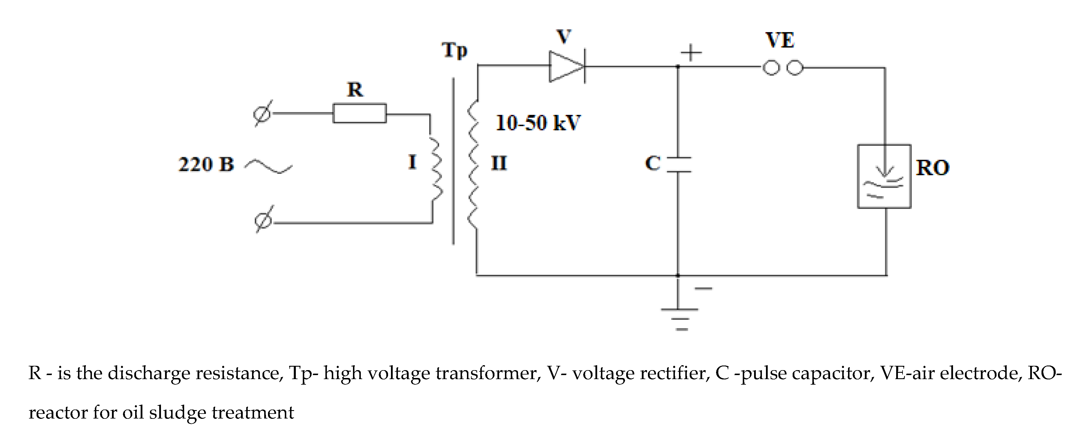
Figure 8.
Thermal reactor circuit for HVSPED wave treatment.
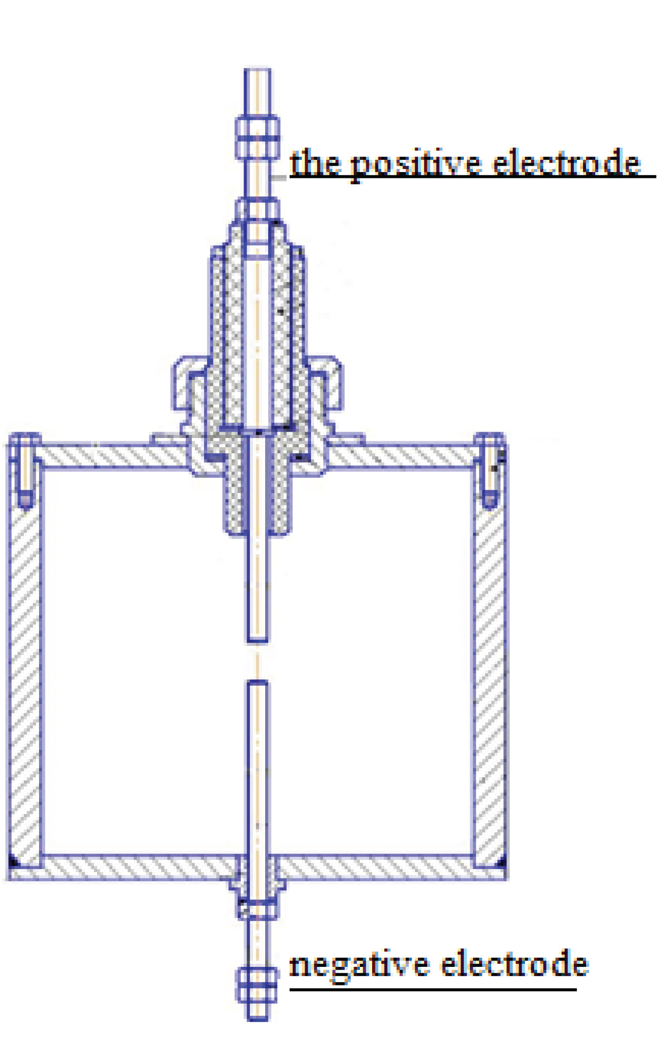

Table 1.
Algebraic expressions of functions f (α) and g (α).
| Mechanism | f(α)=(1/k)(dα/dt) | g(α)=kt |
|---|---|---|
| First order (F1) | (1–α) | –ln(1–α) |
| Second order (F2) | (1–α)2 | (1–α)–1–1 |
| Third orded (F3) | (1–α)3 | [(1–α)–2–1]/2 |
| 3D- diffusions (Jander model) | f(α)=3/2⋅(1−α)2/3⋅[1−(1−α)1/3] | g(α)=[1−(1−α)1/3] |
| Avrami-Erofeev (A2) | 2(1–α) [–ln(1–α)]1/2 | [–ln(1–α)]1/2 |
| Avrami-Erofeev (A3) | 3(1–α) [–ln(1–α)]2/3 | [–ln(1–α)]1/3 |
Table 2.
Kinetic parameters of thermal decomposition of bentonite decomposition before (a, b/BenNi) and after (c, d/BenNiB) leaching with catalyst.
Table 2.
Kinetic parameters of thermal decomposition of bentonite decomposition before (a, b/BenNi) and after (c, d/BenNiB) leaching with catalyst.
| Model | Eₐ, kJ/mol (BenNi) |
A, s⁻¹ (BenNi) |
Eₐ, kJ/mol (BenNiB) |
A, s⁻¹ (BenNiB) |
|---|---|---|---|---|
| F1 | 356.13±1.90 | (4.60±0.14)⋅1054 | 11.58±0.11 | (1.58±0.11)⋅104 |
| F2 | 540.49±1.02 | (4.1±0.93)⋅1080 | 22.08±0.10 | (1.18±0.10)⋅103 |
| F3 | 773.86±1.35 | (1.6±1.39)⋅10113 | 34.93±0.10 | (0.25±0.15)⋅102 |
| 3D Diff. | 308.42±1.08 | (2.7±1.34)⋅1048 | 8.70±0.07 | (9.84±0.08)⋅104 |
| A2 | 189.95±0.85 | (9.9±0.93)⋅1030 | 3.41±0.03 | (2.61±0.20)⋅105 |
| A3 | 133.45±0.79 | (8.9±1.93)⋅1022 | 8.51±0.03 | (6.76±0.25)⋅105 |
Table 3.
Levels of studied factors and intervals of their variation.
| Factors | Unit of measure | Levels | |||
|---|---|---|---|---|---|
| 1 | 2 | 3 | 4 | ||
| Х1, amount of catalyst added | g | 0 | 0.5 | 1 | 1.5 |
| Х2, condensate capacity | µFarads | 0.125 | 0.25 | 0.5 | 0.75 |
| Х3, duration | min | 5 | 6 | 7 | 8 |
| Х4, distance between electrodes | mm | 7 | 8 | 9 | 10 |
Table 4.
Experiment planning matrix.
| № | Х1 | Х2 | Х3 | Х4 | Ymid, % | Ye | Yp |
|---|---|---|---|---|---|---|---|
| 1 | 0 | 0.125 | 5 | 7 | 7.7 | 7.7 | 15.9 |
| 2 | 0.5 | 0.25 | 6 | 8 | 22.1 | 23.1 | 23.3 |
| 3 | 1.0 | 0.5 | 7 | 9 | 21.9 | 21.9 | 20.3 |
| 4 | 1.5 | 0.75 | 8 | 10 | 10.34 | 8.34 | 13.6 |
| 5 | 0 | 0.25 | 7 | 10 | 26.45 | 26.5 | 21.4 |
| 6 | 0.5 | 0.125 | 8 | 9 | 35.2 | 33.2 | 31.8 |
| 7 | 1.0 | 0.75 | 5 | 8 | 21.1 | 22.1 | 19.79 |
| 8 | 1.5 | 0.5 | 6 | 7 | 26.2 | 26.2 | 22,8 |
| 9 | 0 | 0.5 | 8 | 8 | 20.1 | 21.1 | 19.63 |
| 10 | 0.5 | 0.75 | 7 | 7 | 19.3 | 19.3 | 24.62 |
| 11 | 1.0 | 0.125 | 6 | 10 | 28.6 | 28.6 | 31.7 |
| 12 | 1.5 | 0.25 | 5 | 9 | 27,33 | 27.3 | 23.35 |
| 13 | 0 | 0.75 | 6 | 9 | 21.66 | 21.7 | 17.64 |
| 14 | 0.5 | 0.5 | 5 | 10 | 18.5 | 18.5 | 19.53 |
| 15 | 1.0 | 0.25 | 8 | 7 | 22.22 | 20.2 | 25.4 |
| 16 | 1.5 | 0.125 | 7 | 8 | 19.2 | 20.2 | 23.84 |
Note: Үe - fraction yield up to 300℃, Үp - calculated value of partial functions of the generalized equation for each optimization parameter.
Table 5.
Calculated values of individual functions for
| Functions | R | tr | |
|---|---|---|---|
| Y1 = -7.6158x2 + 12.517x + 19.02 | 0.97 | 23.21 | |
| Y2 = -5.4364x2 + 4.8618x + 22.848 | 0.96 | 17.3 | |
| Y3 = -5.7625x2 + 10,079x + 19.233 | 0.75 | 2.42 | |
| Y4 = -7.3823x2 + 13.601x + 17.975 | 0.79 | 2.96 |
Table 6.
Group and individual chemical composition of hydrogenate of fraction with boiling point up to 200℃.
Table 6.
Group and individual chemical composition of hydrogenate of fraction with boiling point up to 200℃.
| № | RT | Area Pct | Library/ID | Qual |
|---|---|---|---|---|
| 1 | 4.03 | 0.0624 | Heptane, 2-methyl- | 81 |
| 2 | 4.14 | 0.0852 | Cyclohexane, 1,4-dimethyl-, trans- | 91 |
| 3 | 5.0124 | 0.3301 | Hexane, 3-methyl- | 64 |
| 4 | 5.55 | 0.1795 | Octane, 2-bromo- | 47 |
| 5 | 5.55 | 0.2722 | Cyclopropane, pentamethyl- | 38 |
| 6 | 5.45 | 0.3846 | Cyclohexane, 1,1,3-trimethyl- | 91 |
| 7 | 5.06 | 0.1608 | Ethylbenzene | 60 |
| 8 | 5.66 | 0.2316 | Cyclohexane, 1,2,4-trimethyl-, (1.alpha.,2.beta.,4.beta.)- | 81 |
| 9 | 6.0136 | 1.0114 | Benzene, 1,3-dimethyl- | 95 |
| 10 | 6.1786 | 0.4719 | Octane, 3-methyl- | 91 |
| 11 | 6.27 | 0.1688 | Cyclohexane, 1,2,4-trimethyl- | 83 |
| 12 | 6.97 | 0.2318 | Benzene, 1,3-dimethyl- | 95 |
| 13 | 6.57 | 0.2320 | Cyclohexane, 1,1,2-trimethyl- | 58 |
| 14 | 6.97 | 0.5736 | cis-1-Ethyl-3-methyl-cyclohexane | 93 |
| 15 | 6.17 | 1.27 | Oxalic acid, isobutyl pentyl ester | 64 |
| 16 | 6.27 | 0.0588 | 3-Hexene, 2-methyl-, (E)- | 53 |
| 17 | 6.27 | 0.4791 | 1-Ethyl-4-methylcyclohexane | 86 |
| 18 | 7.0038 | 0.2054 | Heptane, 3-ethyl-2-methyl- | 49 |
| 19 | 7.1248 | 0.4997 | 1-Hexacosanol | 50 |
| 20 | 7.08 | 1.59 | Octane, 2,6-dimethyl- | 83 |
| 21 | 7.68 | 1.1800 | Octane, 2,3-dimethyl- | 62 |
| 22 | 7.19 | 0.4376 | Benzene, 1-ethyl-3-methyl- | 76 |
| 23 | 7.69 | 0.6891 | Butane, 2,2-dimethyl- | 38 |
| 24 | 7.69 | 0.8500 | Nonane, 4-methyl- | 74 |
| 25 | 7.09 | 1.32 | 2-Octene, 2,6-dimethyl- | 49 |
| 26 | 7.29 | 0.8418 | Nonane, 3-methyl- | 74 |
| 27 | 8.1150 | 0.7349 | Cyclohexene, 1-methyl- | 43 |
| 28 | 8.00 | 1.36 | Benzene, 1-ethyl-4-methyl- | 50 |
| 29 | 8.60 | 0.3904 | 3-Heptene, 4-propyl- | 53 |
| 30 | 8.10 | 0.2996 | 3,4-Diethyl-2-hexene | 38 |
| 31 | 8.10 | 2.85 | Octane, 1,1'-oxybis- | 59 |
| 32 | 8.11 | 0.3003 | Cyclohexane, 1-ethyl-2,3-dimethyl- | 43 |
| 33 | 8.81 | 1.01 | Benzene, 1,3,5-trimethyl- | 50 |
| 34 | 8.41 | 1.63 | Octane, 2-bromo- | 72 |
| 35 | 9.0942 | 0.5872 | 2,4-Hexadiene, 3,4-dimethyl-, (E,Z)- | 38 |
| 36 | 9.42 | 1.1676 | cis-4-Decene | 47 |
| 37 | 9.22 | 0.6664 | Nonane, 3-methyl- | 38 |
| 38 | 9.72 | 0.5040 | Benzene, 1-methyl-4-propyl- | 50 |
| 39 | 9.72 | 0.7640 | Benzene, 2-ethyl-1,4-dimethyl- | 81 |
| 40 | 9.62 | 0.8457 | 1-Ethyl-2,2,6-trimethylcyclohexane | 64 |
| 41 | 9.22 | 0.4584 | 1-Octyn-3-ol, 4-ethyl- | 53 |
| 42 | 9.83 | 0.4611 | Decane, 4-methyl- | 53 |
| 43 | 9.33 | 1.1514 | Decane, 2-methyl- | 60 |
| 44 | 9.53 | 1.1805 | Benzene, 1-ethyl-2,4-dimethyl- | 25 |
| 45 | 9.63 | 0.3626 | Benzene, 2-ethyl-1,4-dimethyl- | 87 |
| 46 | 10.0623 | 0.4126 | Spiro[3.5]nonan-1-one | 41 |
| 47 | 10.1503 | 0.6865 | Cyclohexanecarboxylic acid, 4-propyl-, 2,3-dicyano-4-(pentyloxy)phenyl ester | 59 |
| 48 | 10.44 | 0.6667 | Cyclohexane, 1,1-dimethyl- | 53 |
| 49 | 10.74 | 0.8927 | Cyclopentane, 1-butyl-2-ethyl- | 43 |
| 50 | 10.54 | 3.10 | 3-Methyl-4-nonanone | 53 |
| 51 | 10.24 | 0.4593 | 1,7-Dimethyl-4-(1-methylethyl)cyclodecane | 47 |
| 52 | 10.44 | 0.8054 | Benzene, 1,2,3,4-tetramethyl- | 30 |
| 53 | 10.04 | 0.6847 | Benzene, 1,2,4,5-tetramethyl- | 55 |
| 54 | 10.95 | 1.0749 | trans-Decalin, 2-methyl- | 93 |
| 55 | 10.75 | 0.3421 | Triacontyl acetate | 43 |
| 56 | 10.55 | 0.8277 | Octane, 2-bromo- | 47 |
| 57 | 11.1185 | 1.20 | cis-Decalin, 2-syn-methyl- | 93 |
| 58 | 11.15 | 0.8260 | 2-Undecene, 6-methyl-, (Z)- | 38 |
| 59 | 11.15 | 0.4266 | Cyclohexane, 1,2,3-trimethyl-, (1.alpha.,2.alpha.,3.beta.)- | 64 |
| 60 | 11.96 | 1.0653 | Heptane, 3-ethyl-2-methyl- | 47 |
| 61 | 11.76 | 0.7402 | Undecane, 4-methyl- | 43 |
| 62 | 11.46 | 1.0541 | Triacontyl acetate | 58 |
| 63 | 11.66 | 0.7209 | Nonane, 3-methyl- | 43 |
| 64 | 11.26 | 1.1641 | Naphthalene | 94 |
| 65 | 11.67 | 0.5891 | Benzene, (2-chloro-2-butenyl)- | 58 |
| 66 | 12.1087 | 2.0227 | Cyclohexane, 1-methyl-3-pentyl- | 22 |
| 67 | 12.47 | 3.65 | Undecane, 2,6-dimethyl- | 74 |
| 68 | 12.38 | 0.9914 | Naphthalene, decahydro-1,2-dimethyl- | 70 |
| 69 | 12.08 | 1.72 | Undecane, 2,6-dimethyl- | 87 |
| 70 | 12.38 | 0.5692 | Tetrapentacontane, 1,54-dibromo- | 50 |
| 71 | 12.38 | 0.6868 | Cyclopentane, 1-pentyl-2-propyl- | 50 |
| 72 | 12.18 | 1.53 | Cyclohexane, 2-butyl-1,1,3-trimethyl- | 90 |
| 73 | 13.0549 | 0.6528 | 1(2H)-Naphthalenone, octahydro-3,8a-dimethyl-, (3.alpha.,4a.beta.,8a.alpha.)- | 50 |
| 74 | 13.1099 | 0.8067 | Cyclopentane, 1-pentyl-2-propyl- | 49 |
| 75 | 13.2419 | 0.5027 | Undecane, 2,6-dimethyl- | 41 |
| 76 | 13.2749 | 0.4825 | 3-Nonen-2-one | 43 |
| 77 | 13.3519 | 0.9177 | Benzene, (1-methyl-1-butenyl)- | 25 |
| 78 | 13.4399 | 0.9783 | Dodecane, 2-methyl- | 64 |
| 79 | 13.5500 | 0.8596 | Heneicosyl heptafluorobutyrate | 43 |
| 80 | 13.6380 | 1.01 | Hexadecane, 2,6,10,14-tetramethyl- | 72 |
| 81 | 13.7480 | 0.5249 | Cyclohexanol, 5-methyl-2-(1-methylethyl)-, (1.alpha.,2.beta.,5.alpha.)- | 38 |
| 82 | 13.8470 | 0.9112 | Naphthalene, 2-methyl- | 93 |
| 83 | 13.9350 | 0.9656 | Cyclopentane, 1-pentyl-2-propyl- | 49 |
| 84 | 14.0670 | 2.43 | Hexadecane, 2,6,11,15-tetramethyl- | 72 |
| 85 | 14.1441 | 0.6730 | Benzocycloheptatriene | 38 |
| 86 | 14.2871 | 0.6614 | Phytol | 72 |
| 87 | 14.3971 | 1.1862 | Undecane, 2,6-dimethyl- | 50 |
| 88 | 14.4631 | 0.3308 | 3,3-Dimethyl-hepta-4,5-dien-2-ol | 53 |
| 89 | 14.5621 | 0.6781 | 2,6,10,14,18,22-Tetracosahexaene, 2,6,10,15,19,23-hexamethyl-, (all-E)- | 27 |
| 90 | 14.6722 | 0.6820 | 17-Pentatriacontene | 46 |
| 91 | 14.7492 | 0.4724 | 3-Methyl-2-(2-oxopropyl)furan | 53 |
| 92 | 14.8812 | 0.5827 | 3-Eicosene, (E)- | 72 |
| 93 | 14.9362 | 0.3183 | 1-Decanol, 2-hexyl- | 49 |
| 94 | 14.9802 | 0.4126 | 2-Butanone, 4-(2,6,6-trimethyl-2-cyclohexen-1-yl)-, (R)- | 42 |
| 95 | 15.0682 | 0.4629 | Tridecane, 4-methyl- | 43 |
| 96 | 15.1452 | 0.6712 | Tridecane, 2-methyl- | 60 |
| 97 | 15.2223 | 0.2226 | 2(1H)-Naphthalenone, octahydro-4a-methyl-, cis- | 46 |
| 98 | 15.2773 | 0.8231 | Cycloundecanone | 38 |
| 99 | 15.4093 | 1.0689 | Dodecane, 2,6,10-trimethyl- | 91 |
| 100 | 15.5303 | 0.7387 | Naphthalene, 2,3-dimethyl- | 55 |
| 101 | 15.7503 | 2.63 | Pentadecane | 53 |
| 102 | 15.8384 | 0.3975 | Tridecane, 4,8-dimethyl- | 60 |
| 103 | 15.9704 | 0.7095 | Naphthalene, 2,3-dimethyl- | 97 |
| 104 | 16.0254 | 0.5876 | Naphthalene, 2,6-dimethyl- | 95 |
| 105 | 16.2124 | 0.2798 | Pentadecyl heptafluorobutyrate | 49 |
| 106 | 16.3114 | 0.2988 | Naphthalene, 2,6-dimethyl- | 84 |
| 107 | 16.3555 | 0.3332 | Cyclohexane, 1,2,4,5-tetraethyl-, (1.alpha.,2.alpha.,4.alpha.,5.alpha.)- | 43 |
| 108 | 16.4325 | 0.3160 | Pentadecyl trifluoroacetate | 30 |
| 109 | 16.5865 | 0.9602 | Octacosyl heptafluorobutyrate | 62 |
| 110 | 16.6965 | 0.2596 | Cycloundecanone | 38 |
| 111 | 16.7845 | 0.9205 | Pentadecane, 2,6,10,14-tetramethyl- | 80 |
| 112 | 16.8945 | 0.4629 | Tetradecane, 3-methyl- | 46 |
| 113 | 17.0816 | 0.4321 | Octatriacontyl pentafluoropropionate | 38 |
| 114 | 17.1696 | 0.2247 | 6-Octenal, 3,7-dimethyl- | 49 |
| 115 | 17.2356 | 0.2151 | 1,7-Nonadiene, 4,8-dimethyl- | 41 |
| 116 | 17.3346 | 1.50 | Pentadecane | 87 |
| 117 | 17.4887 | 0.2093 | 2(1H)-Naphthalenone, octahydro-4a-methyl-, cis- | 46 |
| 118 | 17.5657 | 0.1116 | Cyclohexane, 1,2-dimethyl-3-pentyl-4-propyl- | 45 |
| 119 | 17.5987 | 0.1378 | 3-Methyl-2-(2-oxopropyl)furan | 30 |
| 120 | 17.6867 | 0.1542 | Naphthalene, 1,4,6-trimethyl- | 95 |
| 121 | 17.7747 | 0.1783 | Naphthalene, 2,3,6-trimethyl- | 96 |
| 122 | 18.0057 | 0.1329 | Naphthalene, 1,6,7-trimethyl- | 96 |
| 123 | 18.0718 | 0.2291 | 5-(1-Iodo-1-methyl-ethyl)-3,3-dimethyl-dihydro-furan-2-one | 35 |
| 124 | 18.1488 | 0.0988 | Octatriacontyl pentafluoropropionate | 53 |
| 125 | 18.2148 | 0.2406 | Dodecane, 2,6,11-trimethyl- | 60 |
| 126 | 18.3028 | 0.1856 | Nonahexacontanoic acid | 38 |
| 127 | 18.3908 | 0.2212 | Tetrapentacontane, 1,54-dibromo- | 43 |
| 128 | 18.5118 | 0.0776 | 2-Butanone, 4-(2,6,6-trimethyl-2-cyclohexen-1-yl)-, (R)- | 44 |
| 129 | 18.7539 | 0.1109 | Tetrapentacontane, 1,54-dibromo- | 62 |
| 130 | 18.8419 | 0.8327 | Heptacosane | 86 |
| 131 | 19.0399 | 0.0361 | 1-Decanol, 2-hexyl- | 51 |
| 132 | 19.5020 | 0.0839 | Tetrapentacontane, 1,54-dibromo- | 43 |
| 133 | 19.6010 | 0.3119 | Dodecane, 2-methyl- | 72 |
| 134 | 19.6891 | 0.0568 | 1-Decanol, 2-hexyl- | 60 |
| 135 | 19.7551 | 0.0774 | Hexadecane, 2-methyl- | 86 |
| 136 | 19.8761 | 0.0861 | 2-Piperidinone, N-[4-bromo-n-butyl]- | 53 |
| 137 | 20.0961 | 0.1102 | Heptafluorobutyric acid, n-tetradecyl ester | 55 |
| 138 | 20.2612 | 0.5837 | Heptadecane | 97 |
| 139 | 20.4152 | 0.3487 | Pentadecane, 2,6,10,14-tetramethyl- | 96 |
| 140 | 20.9323 | 0.1181 | 2-Piperidinone, N-[4-bromo-n-butyl]- | 55 |
| 141 | 21.0423 | 0.0753 | Dodecane, 2,6,10-trimethyl- | 43 |
| 142 | 21.1413 | 0.0587 | Octatriacontyl pentafluoropropionate | 58 |
| 143 | 21.6254 | 0.3489 | Heptadecane | 86 |
| 144 | 21.8124 | 0.1694 | Hexadecane, 2,6,10,14-tetramethyl- | 90 |
| 145 | 22.9126 | 0.2917 | Tetratetracontane | 83 |
| 146 | 24.1338 | 0.1685 | Eicosane | 98 |
| 147 | 25.3111 | 0.1120 | Heneicosane | 95 |
| 148 | 26.4333 | 0.0785 | Tetratetracontane | 87 |
| 149 | 27.5115 | 0.0499 | Eicosane | 93 |
| 150 | 28.5346 | 0.0432 | Eicosane | 92 |
| 151 | 29.5248 | 0.0438 | Di-n-decylsulfone | 37 |
| 152 | 30.4930 | 0.0482 | 2-Nitro-4-(trifluoromethyl)phenol | 22 |
| 153 | 31.5492 | 0.0539 | Cyclotrisiloxane, hexamethyl- | 46 |
| 154 | 31.9012 | 0.0521 | Di-n-octyl phthalate | 38 |
Table 7.
Group and individual chemical composition of hydrogenate fraction with boiling point up to 300°C.
Table 7.
Group and individual chemical composition of hydrogenate fraction with boiling point up to 300°C.
| № | RT | Area Pct | Library/ID | Qual |
|---|---|---|---|---|
| 1 | 3.11 | 0.2939 | Benzene | 90 |
| 2 | 3.71 | 0.0258 | 1-Heptene | 80 |
| 3 | 3.72 | 0.0541 | Heptane | 86 |
| 4 | 4.93 | 0.0541 | Heptane, 2-methyl- | 90 |
| 5 | 4.13 | 0.0299 | 1-Heptene, 2-methyl- | 80 |
| 6 | 4.63 | 0.0648 | 2-Octene, (Z)- | 68 |
| 7 | 5.0014 | 0.1179 | Hexane, 3-methyl- | 59 |
| 8 | 5.35 | 0.0290 | Cyclohexane, 1,1,3-trimethyl- | 91 |
| 9 | 5.05 | 0.0367 | 1-Heptene, 2,6-dimethyl- | 86 |
| 10 | 5.85 | 0.0253 | Ethylbenzene | 58 |
| 11 | 5.16 | 0.1152 | p-Xylene | 95 |
| 12 | 6.1676 | 0.0522 | Octane, 3-methyl- | 90 |
| 13 | 6.26 | 0.1628 | 1-Nonene | 72 |
| 14 | 6.07 | 0.1795 | Oxalic acid, isobutyl pentyl ester | 72 |
| 15 | 6.07 | 0.0406 | Cyclohexane, 1-ethyl-4-methyl-, trans- | 74 |
| 16 | 7.98 | 0.1008 | Octane, 2,6-dimethyl- | 81 |
| 17 | 7.58 | 0.0455 | Heptane, 3-ethyl-2-methyl- | 47 |
| 18 | 7.88 | 0.0295 | 6-Nitroundec-5-ene | 22 |
| 19 | 7.08 | 0.0723 | Benzene, 1,1'-(1-methyl-1,2-ethanediyl)bis- | 47 |
| 20 | 7.49 | 0.0321 | Acetohydrazide, 2-cyano-N2-[4-(4-methylbenzyloxy)benzylideno]- | 38 |
| 21 | 7.59 | 0.0650 | Nonane, 4-methyl- | 58 |
| 22 | 7.99 | 0.1058 | Cyclohexane, 1,2,3-trimethyl-, (1.alpha.,2.beta.,3.alpha.)- | 46 |
| 23 | 7.19 | 0.0549 | Nonane, 3-methyl- | 50 |
| 24 | 8.90 | 0.2562 | Cyclooctane, 1,2-dimethyl- | 93 |
| 25 | 8.00 | 0.3335 | Sulfurous acid, decyl 2-ethylhexyl ester | 72 |
| 26 | 8.71 | 0.1381 | Benzene, 1,1'-(1-methyl-1,2-ethanediyl)bis- | 43 |
| 27 | 8.21 | 0.1063 | Sulfurous acid, octyl 2-propyl ester | 64 |
| 28 | 9.0831 | 0.0477 | Cyclopentane, 1,2-dimethyl-3-methylene-, cis- | 42 |
| 29 | 9.1821 | 0.1199 | 2H,6H-Cyclopenta[b][1,4]dioxepin, 5a,7,8,8a-tetrahydro-, trans- | 38 |
| 30 | 9.11 | 0.0598 | 7-Octene-2,6-diol, 2,6-dimethyl- | 43 |
| 31 | 9.51 | 0.0611 | Benzene, 1-methyl-3-propyl- | 42 |
| 32 | 9.62 | 0.0788 | 1,3,8-p-Menthatriene | 81 |
| 33 | 9.42 | 0.0944 | 1-Ethyl-2,2,6-trimethylcyclohexane | 80 |
| 34 | 9.12 | 0.0465 | Heptane, 3-ethyl-2-methyl- | 43 |
| 35 | 9.12 | 0.1910 | Cyclodecene | 55 |
| 36 | 9.42 | 0.1395 | Benzene, 4-ethyl-1,2-dimethyl- | 25 |
| 37 | 9.53 | 0.0360 | Benzene, 4-ethyl-1,2-dimethyl- | 76 |
| 38 | 10.0293 | 0.2956 | Ammonia | 3 |
| 39 | 10.1283 | 0.1355 | 2-Octene, 2-methyl-6-methylene- | 47 |
| 40 | 10.1833 | 0.2851 | Cyclopentane, hexyl- | 72 |
| 41 | 10.53 | 0.0765 | Cyclohexane, 1-ethyl-2-propyl- | 64 |
| 42 | 10.33 | 0.6214 | Silane, trichlorooctadecyl- | 78 |
| 43 | 10.04 | 0.0837 | Ketone, 2,2-dimethylcyclohexyl methyl | 38 |
| 44 | 10.24 | 0.1083 | Cyclobutene, bis(1-methylethylidene)- | 38 |
| 45 | 10.84 | 0.1136 | Benzene, 1,2,4,5-tetramethyl- | 90 |
| 46 | 10.84 | 0.1918 | trans-Decalin, 2-methyl- | 95 |
| 47 | 10.34 | 0.1383 | Undecane, 2,6-dimethyl- | 47 |
| 48 | 11.1075 | 0.4033 | cis-Decalin, 2-syn-methyl- | 93 |
| 49 | 11.35 | 0.2132 | Benzene, 4-ethyl-1,2-dimethyl- | 81 |
| 50 | 11.95 | 0.0820 | 3-Ethyl-6-trifluoroacetoxyoctane | 43 |
| 51 | 11.75 | 0.2234 | Octane, 2,3-dimethyl- | 43 |
| 52 | 11.65 | 0.1720 | 3,4-Dimethylcyclohexanol | 27 |
| 53 | 11.36 | 0.2340 | Triacontyl acetate | 58 |
| 54 | 11.56 | 0.1671 | Triacontyl acetate | 38 |
| 55 | 11.16 | 0.3378 | Naphthalene | 94 |
| 56 | 11.56 | 0.1699 | 2-Butene, 3-chloro-1-phenyl-, (Z)- | 53 |
| 57 | 12.0646 | 0.2934 | Cyclopentane, 1-butyl-2-propyl- | 53 |
| 58 | 12.0976 | 0.4047 | Oxalic acid, cyclohexylmethyl octyl ester | 27 |
| 59 | 12.27 | 1.91 | Pentadecane, 2,6,10-trimethyl- | 53 |
| 60 | 12.27 | 0.3368 | Naphthalene, decahydro-2,6-dimethyl- | 52 |
| 61 | 12.97 | 0.6507 | Undecane, 2,6-dimethyl- | 87 |
| 62 | 12.18 | 0.1620 | (2-Acetyl-5-methyl-cyclopentyl)-acetic acid | 53 |
| 63 | 12.28 | 0.2650 | 6-Octen-1-ol, 3,7-dimethyl-, formate | 38 |
| 64 | 12.08 | 0.5840 | Cyclohexane, 2-butyl-1,1,3-trimethyl- | 83 |
| 65 | 13.0438 | 0.2613 | Cyclohexanol, 5-methyl-2-(1-methylethenyl)- | 49 |
| 66 | 13.0988 | 0.3848 | 6-Octen-1-ol, 3,7-dimethyl-, acetate | 47 |
| 67 | 13.2308 | 0.2164 | E-9-Methyl-8-tridecen-2-ol, acetate | 43 |
| 68 | 13.2639 | 0.2215 | 2-Propionyl-1-pyrroline | 43 |
| 69 | 13.3409 | 0.4574 | Cyclohexane, 1,2,3-trimethyl-, (1.alpha.,2.alpha.,3.beta.)- | 20 |
| 70 | 13.4289 | 0.4030 | Dodecane, 2-methyl- | 50 |
| 71 | 13.5389 | 0.4295 | Cycloundecanone | 43 |
| 72 | 13.6269 | 0.8699 | Octane, 2-bromo- | 64 |
| 73 | 13.7479 | 0.2984 | 6-Octen-1-ol, 3,7-dimethyl-, acetate | 49 |
| 74 | 13.8470 | 0.6633 | Benzocycloheptatriene | 89 |
| 75 | 13.9240 | 0.5894 | Cyclopentane, 1-pentyl-2-propyl- | 50 |
| 76 | 14.0450 | 1.58 | Dodecane, 2,6,11-trimethyl- | 53 |
| 77 | 14.1220 | 0.4593 | Benzocycloheptatriene | 89 |
| 78 | 14.2320 | 0.2355 | Cyclohexanone, 2,2-dimethyl-5-(3-methyloxiranyl)-, [2.alpha.(R*),3.alpha.]-(.+-.)- | 49 |
| 79 | 14.2760 | 0.2101 | Sulfurous acid, butyl heptadecyl ester | 47 |
| 80 | 14.3860 | 0.7843 | Tridecane, 6-methyl- | 43 |
| 81 | 14.4521 | 0.2559 | 3,3-Dimethyl-hepta-4,5-dien-2-ol | 59 |
| 82 | 14.5511 | 0.5550 | 6-Octenal, 3,7-dimethyl-, (R)- | 43 |
| 83 | 14.6721 | 0.5479 | 7-Octenal, 3,7-dimethyl- | 49 |
| 84 | 14.7491 | 0.4097 | Cyclodecanone, oxime | 38 |
| 85 | 14.8701 | 0.5092 | 1-Docosene | 50 |
| 86 | 14.9252 | 0.2589 | 2,6,10-Trimethylundeca-1,3-diene | 49 |
| 87 | 14.9802 | 0.4098 | Pentadecyl heptafluorobutyrate | 38 |
| 88 | 15.0572 | 0.4117 | Tridecane, 4-methyl- | 45 |
| 89 | 15.1452 | 0.5656 | Tridecane, 2-methyl- | 55 |
| 90 | 15.2112 | 0.2729 | 2(1H)-Naphthalenone, octahydro-4a-methyl-, cis- | 55 |
| 91 | 15.2662 | 0.8078 | 2,6,10-Trimethylundeca-1,3-diene | 35 |
| 92 | 15.4092 | 0.9459 | Dodecane, 2,6,10-trimethyl- | 91 |
| 93 | 15.5523 | 1.0102 | Cyclododecane, ethyl- | 60 |
| 94 | 15.6733 | 0.3638 | 9-Oxabicyclo[6.1.0]nonane, 1-methyl-, cis- | 38 |
| 95 | 15.7393 | 2.17 | Heptacosane | 59 |
| 96 | 15.8273 | 0.4834 | 2-Piperidinone, N-[4-bromo-n-butyl]- | 72 |
| 97 | 15.9703 | 0.9595 | Naphthalene, 2,3-dimethyl- | 97 |
| 98 | 16.0253 | 0.7945 | Naphthalene, 2,7-dimethyl- | 95 |
| 99 | 16.2124 | 0.4809 | 1,2-Cyclohexanediol, cyclic sulfite, trans- | 42 |
| 100 | 16.3114 | 0.5301 | Naphthalene, 2,7-dimethyl- | 93 |
| 101 | 16.3444 | 0.5489 | Naphthalene, 2,6-dimethyl- | 56 |
| 102 | 16.4874 | 0.8824 | Decahydro-4,4,8,9,10-pentamethylnaphthalene | 43 |
| 103 | 16.5754 | 1.32 | Cyclotetradecane | 78 |
| 104 | 16.6965 | 0.5090 | Cyclohexanol, 5-methyl-2-(1-methylethyl)-, (1.alpha.,2.beta.,5.alpha.)- | 46 |
| 105 | 16.7845 | 1.62 | Pentadecane, 2,6,10,14-tetramethyl- | 72 |
| 106 | 16.8945 | 0.7663 | Cycloundecanone | 41 |
| 107 | 16.9825 | 0.4095 | Naphthalene, 2-ethenyl- | 38 |
| 108 | 17.0815 | 0.9639 | Hexatriacontyl pentafluoropropionate | 38 |
| 109 | 17.1696 | 0.6796 | Heptadecyl trifluoroacetate | 50 |
| 110 | 17.2246 | 0.5557 | 9-Oxabicyclo[6.1.0]nonane, 1-methyl-, cis- | 38 |
| 111 | 17.3346 | 2.36 | Pentadecane | 87 |
| 112 | 17.4996 | 0.6506 | Cyclohexanol, 5-methyl-2-(1-methylethenyl)- | 38 |
| 113 | 17.6096 | 0.8625 | Cyclohexanepropanol, 2,2-dimethyl-6-methylene- | 42 |
| 114 | 17.6866 | 0.6123 | Naphthalene, 1,6,7-trimethyl- | 96 |
| 115 | 17.7747 | 0.7137 | Naphthalene, 1,6,7-trimethyl- | 98 |
| 116 | 17.9067 | 0.4211 | 7,9-Dimethyl-1,4-dioxa-7,9-diazacycloundecane-8-thione | 59 |
| 117 | 18.0057 | 0.6789 | Naphthalene, 1,6,7-trimethyl- | 98 |
| 118 | 18.0717 | 0.8225 | Naphthalene, 1,6,7-trimethyl- | 94 |
| 119 | 18.1487 | 0.4326 | Cyclohexanone, 2,2-dimethyl-5-(3-methyloxiranyl)-, [2.alpha.(R*),3.alpha.]-(.+-.)- | 55 |
| 120 | 18.2147 | 0.8709 | 1-Bromodocosane | 58 |
| 121 | 18.3028 | 0.8246 | Nonahexacontanoic acid | 30 |
| 122 | 18.3908 | 1.0661 | Tetrapentacontane, 1,54-dibromo- | 46 |
| 123 | 18.5118 | 0.8860 | Bicyclo[2.2.1]heptane-2,5-dione, 1,7,7-trimethyl- | 46 |
| 124 | 18.6328 | 0.4577 | Azulene, 4,6,8-trimethyl- | 53 |
| 125 | 18.6878 | 0.5572 | 1-Heneicosanol | 76 |
| 126 | 18.7538 | 0.5812 | Tetrapentacontane, 1,54-dibromo- | 52 |
| 127 | 18.8419 | 2.40 | Heptadecane | 90 |
| 128 | 18.9299 | 0.4975 | 1-Decanol, 2-hexyl- | 51 |
| 129 | 19.0399 | 0.8930 | 1-Decanol, 2-hexyl- | 51 |
| 130 | 19.1059 | 0.5229 | 3-Oxoquinuclidine ehylene acetal | 30 |
| 131 | 19.1829 | 0.5019 | 9-Oxabicyclo[6.1.0]nonane, 1-methyl-, cis- | 38 |
| 132 | 19.2489 | 0.3884 | Cyclohexanepropanol, 2,2-dimethyl-6-methylene- | 55 |
| 133 | 19.5130 | 1.0272 | Dodecane, 3-methyl- | 45 |
| 134 | 19.6010 | 1.89 | Dodecane, 2-methyl- | 72 |
| 135 | 19.6890 | 0.5262 | 2-Piperidinone, N-[4-bromo-n-butyl]- | 55 |
| 136 | 19.7660 | 0.7047 | Hexadecane, 2-methyl- | 90 |
| 137 | 19.8760 | 1.0400 | Dodecane, 2,6,10-trimethyl- | 43 |
| 138 | 19.9751 | 0.6107 | 2,6,10-Dodecatrien-1-ol, 3,7,11-trimethyl- | 35 |
| 139 | 20.1291 | 1.93 | 9,9-Dimethoxybicyclo[3.3.1]nona-2,4-dione | 95 |
| 140 | 20.2721 | 2.46 | Heptadecane | 95 |
| 141 | 20.4261 | 2.1159 | Pentadecane, 2,6,10,14-tetramethyl- | 94 |
| 142 | 20.6022 | 0.8528 | Cyclohexane, 1,2-dimethyl-3-pentyl-4-propyl- | 60 |
| 143 | 20.7782 | 0.6346 | Heneicosyl heptafluorobutyrate | 46 |
| 144 | 20.9432 | 1.78 | 2-Piperidinone, N-[4-bromo-n-butyl]- | 55 |
| 145 | 21.0532 | 0.8313 | Tetrapentacontane, 1,54-dibromo- | 68 |
| 146 | 21.1412 | 0.8349 | Cyclododecane, ethyl- | 49 |
| 147 | 21.2623 | 0.4669 | Heptadecane, 3-methyl- | 83 |
| 148 | 21.3283 | 0.7137 | 1,10b(2H)-Dihydropyrano[3,4,5-jk]fluorene | 60 |
| 149 | 21.4163 | 0.3428 | Fumaric acid, allyl octyl ester | 92 |
| 150 | 21.4933 | 0.6399 | 9,9-Dimethoxybicyclo[3.3.1]nona-2,4-dione | 94 |
| 151 | 21.6254 | 1.52 | Heneicosane | 91 |
| 152 | 21.7244 | 0.3975 | 9,9-Dimethoxybicyclo[3.3.1]nona-2,4-dione | 89 |
| 153 | 21.8234 | 1.19 | Hexadecane, 2,6,10,14-tetramethyl- | 94 |
| 154 | 21.9224 | 0.5480 | 9,9-Dimethoxybicyclo[3.3.1]nona-2,4-dione | 70 |
| 155 | 21.9994 | 0.4830 | Cyclohexane, 1,2-dimethyl-3-pentyl-4-propyl- | 50 |
| 156 | 22.1424 | 0.6439 | Cyclotetradecane, 1,7,11-trimethyl-4-(1-methylethyl)- | 60 |
| 157 | 22.1865 | 0.4370 | Cyclotetradecane, 1,7,11-trimethyl-4-(1-methylethyl)- | 55 |
| 158 | 22.2415 | 0.3497 | Cyclotetradecane, 1,7,11-trimethyl-4-(1-methylethyl)- | 64 |
| 159 | 22.3185 | 0.4716 | Fumaric acid, allyl octyl ester | 59 |
| 160 | 22.4065 | 0.4482 | Hexacosyl heptafluorobutyrate | 50 |
| 161 | 22.4615 | 0.4844 | Octatriacontyl pentafluoropropionate | 62 |
| 162 | 22.5715 | 0.6310 | Benzene, 1-methoxy-4-(phenylmethyl)- | 44 |
| 163 | 22.6925 | 0.6743 | 9,9-Dimethoxybicyclo[3.3.1]nona-2,4-dione | 90 |
| 164 | 22.8026 | 0.4300 | Triacontyl pentafluoropropionate | 55 |
| 165 | 22.9126 | 1.14 | Tetratetracontane | 87 |
| 166 | 23.0446 | 0.4414 | 9,9-Dimethoxybicyclo[3.3.1]nona-2,4-dione | 90 |
| 167 | 23.1656 | 0.7514 | Tetratriacontyl heptafluorobutyrate | 42 |
| 168 | 23.3087 | 0.2575 | Dotriacontyl heptafluorobutyrate | 41 |
| 169 | 23.4407 | 0.4035 | Tetrapentacontane, 1,54-dibromo- | 70 |
| 170 | 23.5067 | 0.5492 | Fumaric acid, allyl octyl ester | 90 |
| 171 | 23.6497 | 0.3634 | Tetratriacontyl trifluoroacetate | 55 |
| 172 | 23.7047 | 0.2882 | Tetrapentacontane, 1,54-dibromo- | 64 |
| 173 | 23.7707 | 0.1960 | Z-8-Methyl-9-tetradecen-1-ol acetate | 50 |
| 174 | 23.8257 | 0.3551 | Octatriacontyl pentafluoropropionate | 55 |
| 175 | 23.9028 | 0.3324 | 2,6-Dimethyldibenzothiophene | 93 |
| 176 | 24.0238 | 0.5396 | Tetratriacontyl heptafluorobutyrate | 60 |
| 177 | 24.1448 | 1.13 | Eicosane | 98 |
| 178 | 24.2878 | 0.2573 | Fumaric acid, allyl octyl ester | 80 |
| 179 | 24.3758 | 0.2827 | Fumaric acid, allyl octyl ester | 78 |
| 180 | 24.6179 | 0.4007 | 11-Hexadecenoic acid, 15-methyl-, methyl ester | 95 |
| 181 | 24.6949 | 0.4724 | Tetrapentacontane, 1,54-dibromo- | 60 |
| 182 | 24.8379 | 0.2273 | Octadecane, 2-methyl- | 72 |
| 183 | 24.9039 | 0.2508 | Cyclotetradecane, 1,7,11-trimethyl-4-(1-methylethyl)- | 64 |
| 184 | 25.0029 | 0.2976 | 11-Hexadecenoic acid, 15-methyl-, methyl ester | 55 |
| 185 | 25.1020 | 0.4105 | N1-Tetrahydrofuran-2-ylmethyl-2-(4-chlorobenzylidene)hydrazine-1-carbothioamide | 91 |
| 186 | 25.2120 | 0.2257 | Cyclotetradecane, 1,7,11-trimethyl-4-(1-methylethyl)- | 93 |
| 187 | 25.3110 | 0.8099 | Heneicosane | 93 |
| 188 | 25.7621 | 0.3038 | N1-Tetrahydrofuran-2-ylmethyl-2-(4-chlorobenzylidene)hydrazine-1-carbothioamide | 91 |
| 189 | 26.1581 | 0.2070 | 11-Hexadecenoic acid, 15-methyl-, methyl ester | 96 |
| 190 | 26.3452 | 0.1246 | Fumaric acid, allyl octyl ester | 78 |
| 191 | 26.4332 | 0.5697 | Eicosane | 91 |
| 192 | 26.8623 | 0.1066 | Tetrapentacontane, 1,54-dibromo- | 60 |
| 193 | 26.9063 | 0.1674 | N1-Tetrahydrofuran-2-ylmethyl-2-(4-chlorobenzylidene)hydrazine-1-carbothioamide | 91 |
| 194 | 27.5114 | 0.3700 | Octacosane | 91 |
| 195 | 28.5346 | 0.2522 | Tetracosane | 89 |
| 196 | 29.5248 | 0.2440 | Tetratetracontane | 83 |
| 197 | 30.4929 | 0.2915 | Octacosane | 83 |
| 198 | 31.5491 | 0.2592 | Eicosane | 98 |
| 199 | 31.9012 | 0.0178 | Isophthalic acid, allyl octyl ester | 27 |
Table 8.
Chemical composition and physicochemical properties of oil sludge (Atasu–Alashankou).
| Description, unit | Value |
|---|---|
| Density at 20°С, kg/m3 | 873.0 |
| Density of oil sludge at 15°C, kg/m3 | 865.8 |
| Solidification temperature,°С | 25 |
| Viscosity at 70°С, cSt | 30 |
| Ash content А, % | 0.36 |
| Moisture content, % масс. | 10.2 |
| Total Sulfur S, % | 0.21 |
| Carbon content C, % | 72.4 |
| Hydrogen content H, % | 11.2 |
| Nitrogen content N, % | 0.12 |
| Oxygen content O, % | 17.2 |
| Chlorine salts content, mg/dm3 | 16.4 |
| Atomic ratio of hydrogen to carbon in oil sludge | 1.8 |
| Mass fraction of paraffins, % | 3.0 |
| Methyl and ethyl mercaptans, ppm, mln-1(ppm) | 0.9 |
| Kinematic viscosity, m2/с (cSt) | 29.1 |
| Fractional composition, mass fraction,% | - |
| Up to 200°С | 23 |
| 300°С | 42 |
| 350°С | 19 |
Table 9.
Values of specific surfaces of bentonite.
| Sample | SBET, (m2/g) |
S mesoporous , (m2/g) |
SMICRO, (m2/g) |
Voбщ, (cm3/g) |
V mesoporous (cm3/g) |
VMICRO, (cm3/g) |
pore size, nm |
|---|---|---|---|---|---|---|---|
| Bentonite Ni1% | 76 | 65 | 11 | 0.033 | 0.028 | 0.005 | 2 |
Table 10.
Phase composition according to XRD data.
| 2θ (approximate),° | d, Å (calculated) | Possible phases/indices | Comments | |
|---|---|---|---|---|
| 1 | 21.0 | 4.2269 | Kaolin/clay phases (reflex 00l/0kl), possible kaolinite (α phase) or amorphous aluminosilicates | A peak in the region of 20-22° is often found in kaolini-ta/albite-like components; can also be bound to a polycrystalline clay complex. |
| 2 | 26.5 | 3.3608 | Quartz (SiO₂), approximately (101) | Very typical strong quartz reflex - often found in bentonites as an impurity. |
| 3 | 28.0 | 3.1841 | Plagioclase/feldspar/other silicates | May correspond to leftspar or other silicate impurities |
| 4 | 35.0 | 2.5616 | Aluminosilicate reflexes (montmorillonitol/muscovite/alternatively Ni-containing oxides) | The intensity is average - xacterna for the matrix of bentonite or secondary phases. |
| 5 | 40.5 | 2.2255 | Feldspars/aluminosilicates/possible me-tall oxides | Weak reflex, can be an overlap of several phases |
| 6 | 44.0 | 2.0563 | Ni (metallic, plane 111) and/or NiO (oxide) - reflex from Al/Fe oxides is also possible | The 43-44° ~ reflex is typical for metallic nickel (Ni 111 ≈ 44.5°) and for NiO (oxide) |
Table 11.
Dynamics of power consumption and power of HVSPED unit.
| T, min Processing time |
E, J Energy consumption |
R, W Power consumption |
N Number of discharges |
|---|---|---|---|
| 5 | 10 | 60 | ~300 |
| 6 | 12 | 72 | ~500 |
| 7 | 14 | 84 | ~800 |
| 8 | 16 | 96 | ~1000 |
Disclaimer/Publisher’s Note: The statements, opinions and data contained in all publications are solely those of the individual author(s) and contributor(s) and not of MDPI and/or the editor(s). MDPI and/or the editor(s) disclaim responsibility for any injury to people or property resulting from any ideas, methods, instructions or products referred to in the content. |
© 2025 by the authors. Licensee MDPI, Basel, Switzerland. This article is an open access article distributed under the terms and conditions of the Creative Commons Attribution (CC BY) license (http://creativecommons.org/licenses/by/4.0/).
Copyright: This open access article is published under a Creative Commons CC BY 4.0 license, which permit the free download, distribution, and reuse, provided that the author and preprint are cited in any reuse.


