
Submitted:
01 December 2025
Posted:
02 December 2025
You are already at the latest version
Abstract
Shipborne UAV-assisted dock is an important way to recover unmanned systems for remote water surface low-altitude detection. The lack of resisting deck disturbances capability for UAV autonomous landing in dynamic dock stations has led to the inability of traditional hovering recovery methods for single UAV guidance and flight attitude control systems to meet the growing demand for landing assistance. In this work, we present a shipborne manipulator arm designed for grasping drones that utilize low-altitude visual servo to land on the water surface. The shipborne manipulator arm is fabricated as a key component of a seaplane drone dock comprising a ship-type embedded drone storage, a packaged helistop for power transfer and UAV recovery, and a multi-degree-of-freedom arm integrated multi-source information sensors for the treatment of air to a water-related airplane crash. Dynamics model tests have demonstrated that the end-effector of the shipborne manipulator arm stabilizes and performs optimally for water surface disturbances. A down-to-top grasp docking paradigm for a UAV-assisted perching on shipborne helistop that enables the charging components of the station system to be equipped automatically to ensure that the drone performs its mission in the best condition is also presented. The efficacy of this grasp paradigm when compared with a previous top-to-down model without power recovery has been verified by retrieving vessels in the military fields.
Keywords:
low-altitude drones
; unmanned aerial vehicle
; UAV dock station
; shipborne manipulator
; autonomous landing
1. Introduction
The offshore hydro-meteorological environment is characterized by more intense sea and air flows, accelerating eddy processes, and a sudden increase in uncertain factors. Whether the various monitoring units in the atmospheric unmanned system can be quickly connected and coordinated will be the key to gaining forecasting advantages [1]. The UAV (Unmanned Aerial Vehicle) and ship coordinations have become the main way to observe offshore hydro-meteorological environment, and the implementation of aerial forecasting requires the reliable long-cycle informations to early monitoring. Drone flight limits of shore-based and airborne radar detections can no longer meet the long-cycle needs of aerial early monitoring, which will cause serious constraints to the effectiveness of offshore remote accurate forecasting.
Some ambitious works[2,3,4,5] have investigated the bio-inspired perching and resting way by adding multidegree-of-freedom perching gears at the button of the UAV. This is a difficult scheme to get dual-docking stabilisation, and the cost of modifying the UAV and the impact on the UAV’s flight-control performance are too great to be suitable for technological diffusion. Meanwhile, some other extensive works [6,7] focus on improvising the single UAV autonomous landing technology by enhance guidance and flight attitude control systems. Their main requirement is robustness, meaning the ability to land in the presence of various disturbances. Visual-based trajectory planning is the basic method for landing on a moving platform. Such methods are described in [8,9,10]. More advanced controller such as deep learning algorithm is used in [11]. These are good solutions when UAVs have to be operated above water, but it can be challenging to design a robust docking station which can be used in severe wave conditions. They are best suited for small water surfaces with calm water conditions. The lack of resisting deck disturbances capability for UAV autonomous landing in dynamic dock stations has led to the inability of traditional hovering recovery methods for single UAV guidance and flight attitude control systems to meet the growing demand for landing assistance.
This problem is addressed and is being partially solved by using shipborne dock stations which provide an aircraft to land safely, charge (or change) the batteries and to take-off as well as being safely stored [12,13,14]. The shipborne dock comprise a ship-type embedded drone storage, a packaged helistop for power transfer and UAV recovery. Based on this, the shipborne drones round robin on duty and periodically return land on the UAV station to charge power, with the unique advantage of all-time all-weather and mobile replenishment carrier, this method can obtain large-depth and wide-range hydrographic situation and target information without the restriction of offshore sea and air, which is regarded as a potential scheme to enhance the endurance capability of the UAV, and it has gradually become an important force for ship-to-UAV landing [15,16].
This approach refers to the use of shipborne UAV dock station modified by water surface vessels or floating UAV dock placed at the fixed supply points in the aerial waterway to provide UAVs with functional services such as power supply, status monitoring, storage data processing and equipment management, etc., so as to realise semi-automated management of the UAV batteries and indirectly enhance the endurance of UAVs. UAV dock station represent a critical technology for improving the operational efficiency of UAV recovery systems. In land-based scenarios, drone stations utilizing hovering recovery methods have demonstrated significant effectiveness. With the expansion of UAV applications from terrestrial to marine environments, recovery and docking technologies must meet increasingly stringent requirements to adapt to complex and dynamic maritime conditions [17]. The working mode of shipborne UAV dock station is that after the mounted UAV round robin aerial monitor is completed, it will land on the helistop in the station to charge or replace the battery. After the current hydro-meteorological monitoring is completed, the UAV will follow the shipborne UAV dock station to the next working area until all offshore hydro-meteorological monitoring operations are completed.
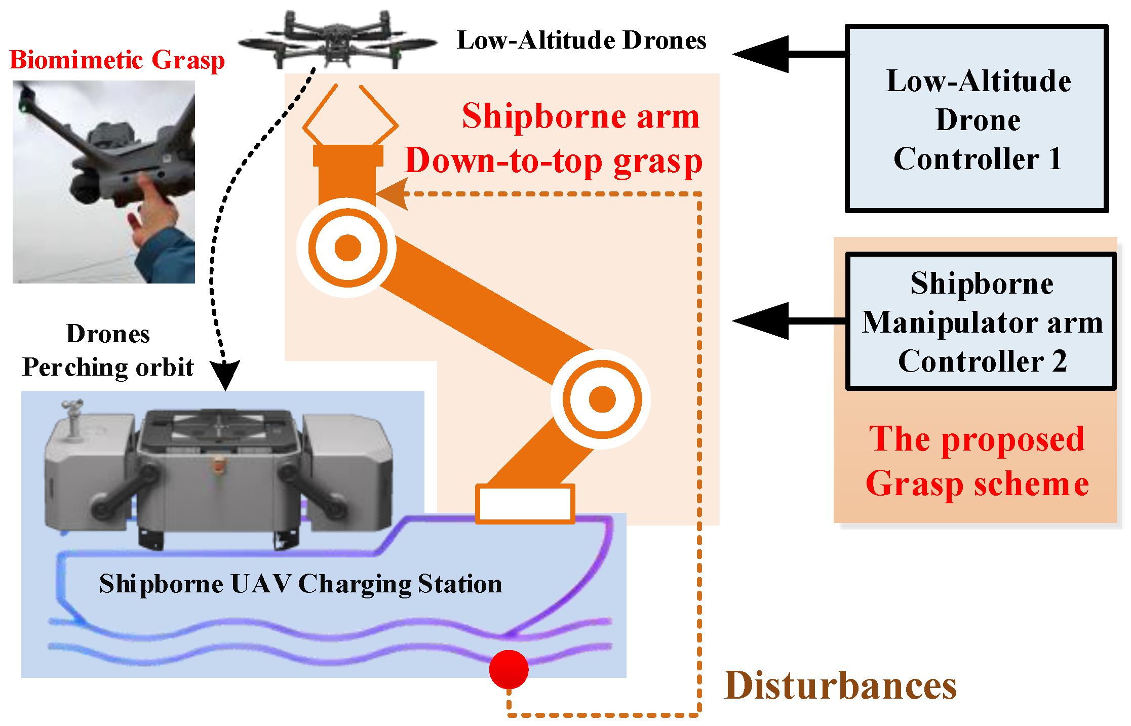
Currently, limited by the compact deck space and water/airflow disturbances, the traditional UAV autonomous perching technology is hard to meet the zero force docking requirements [18,19,20] when shipborne UAV dock station contact with drones. Some great works [21,22,23] have investigated the bio-inspired perching and resting way by adding multi-degree-of-freedom perching gears at the button of the UAV. This is a difficult scheme to get dual-docking stabilisation, and the cost of modifying the UAV and the impact on the UAV’s flight-control performance are too great to be suitable for technological diffusion. Based on these, in this work, we try to install a multi-degree-of-freedom manipulator arm on the ship, and the shipborne manipulator arm is a useful scheme to combine mobile docking stations with vessels operating on the water surface and multirotor UAVs. This kind of system can increase the safety and range of multirotor drones during missions when flying over large water surfaces[24,25,26,27], as shown in Figure Section 1. Due to the strong force coupling of the dual-docking between manipulator and the UAV, minor deviations can lead to the UAV crash and the ship damage. It is a extremely big challenge on dual-docking force control of shipffborne manipulators for UAV docking.
Figure 1.
The down-to-top grasp drones paradigm for shipborne UAV dock stations.
From the perspective of UAV-manipulator collaborative operations, soft landing performance critically depends on the coordination accuracy between UAV autonomous landing trajectory planning and the manipulator’s flexible grasping control. To achieve millimeter-level safe landing under complex maritime conditions, a coupled dynamic model integrating UAV aerodynamics and manipulator impedance characteristics is essential [28]. Traditional methods often decouple UAV landing control and manipulator grasping into independent processes: first aligning the UAV through attitude adjustments for coarse positioning, then activating the manipulator grasping protocol. Such sequential control strategies neglect the dynamic coupling among ship motion, airflow disturbances, and manipulator compliance, leading to excessive landing impact forces (large than 15N) or increased grasping instability risks [29].
The main contributions of the present work are as follows:
1) Aiming at mixed flow field disturbance problem faced by UAV when landing on water surface, We present the first manipulator arm designed for charging shipborne drones that utilize low-altitude visual servo grasp-docking their UAV to land on the water surface.
2) We present a global Jacobian matrix which covers not only the six degree-of-freedom (DOF) of the manipulator arm, but also the nonholonomic shipborne base is derived using the kinematic differential equation. Then it is substituted into a convergence control law to obtain the visual servo control rule that covers the whole dock station.
3) We also present a down-to-top grasp docking paradigm for a UAV-assisted perching on shipborne helistop that enables the charging components of the station system to be equipped automatically to ensure that the drone performs its mission in the best condition.
This paper is organized as follows: Section 2 introduces a global mathematical model of the shipborne manipulator arm and its global Jacobian matrix. In Section 3, a down-to-top grasp docking paradigm are proposed to stabilize UAV-assisted Landing by the end-effector of the shipborne manipulator arm. Experimental results and discussions are also given in this Section. Conclusions are drawn in Section 4.
2. Global Dynamic Model and Global Jacobian Matrix
In this section, a global Jacobian matrix which covers not only the six-DOF of the manipulator arm, but also the nonholonomic shipborne base is established. The complete dynamics model of the ship-to-arm for UAV-assisted perching is formulated.
2.1. Global Dynamics of the Shipborne Grasping Arm
The global coordinate frame of the shipborne manipulator is shown in Figure 2. denotes inertial coordinate system, and denotes ship coordinate system with the origin being the center of mass of the ship. Furthermore, , and denote the centroids of shoulder, elbow and wrist joints of the manipulator as the center of the circle respectively. Employing the Newton–Euler iteration law and the rigid body Denavit–Hartenberg transformation law, the dynamic model of the shipborne manipulator can be written as [30]:
where denotes the workspace position of the manipulator’s end-effector in the inertial coordinate system; denotes velocity vector of the surge, sway and yaw velocities within the ship-fixed frame; denotes angular velocities of the shoulder, elbow and wrist joints; denote the Jacobian matrix of the ship and the manipulator in their respective coordinate system; denotes the state vector; denotes the ship position in the inertial coordinate system; ; denote the manipulator inertial mass and Coriolis force matrix; denotes gravitational moment; denotes the joint driving torques; denotes the disturbances generated by joint friction; denote the inertial and centripetal forces acting on the end-effector due to the ship movements.
In the Figure 2, analyze the mechanical coupling correlation of composite flow fields such as wave, current and wind, identify the main disturbance source characteristics of the correlation of composite flow fields. Determine the motion model boundaries and switching conditions with multiple disturbance sources. In the inertial coordinate system, based on dynamic main cause interference sources, the dynamic main coupling force is defined in the forward, roll and yaw plane motions and the ship motion model can be written as:
where denotes the rotation matrix; denotes the yaw angle; , and denote nominal part of the inertia matrix, Coriolis centripetal force matrix and damping matrix of the ship model, respectively; The term denotes the inertial and centripetal force acting on the ship due to the movement of the manipulator; denotes the ship control torque; denotes external main coupling disturbances.
The dynamics model of the shipborne manipulator arm were visualized and simulated in ROS2 using RViz, as shown in the Figure 3. The models include the ship’s hilspot, the 6-DoF manipulator’s joints, and the end-effector. The coordinate frames of the ship and manipulator are defined in RViz, aligning with the dynamic model described in Figure 2.
2.2. Global Jacobian Matrix and Kinematics of the Shipborne Grasping Arm
The modified Denavit-Hartenberg parameters are needed to establish its configuration of the shipborne manipulator serial arm, as shown in the Figure 4. They are the angle between two adjacent joint axes , the translation length from the origin of one joint axis coordinate system to the origin of the next joint axis coordinate system , the angle of rotation of the next rod relative to this rod , and the translation length of the coordinate origin of the next axis relative to this axis along z the direction .
In terms of the serial manipulator arm, the transformation from one axis to the next can be written as:
For the shipborne 6-degrees-of-freedom serial robotic arm, the transformation of the coordinate system of its link relative to the base coordinate system can be written as:
If any point i on the coordinate system is expressed as , where , then its position in the base coordinate system of the robot can be written as:
where we can get:
By taking the differential of the joint angle from 0 to i, the Jacobian matrix of the translation part can be written as:
where the Jacobian matrix of the rotation part is the differential of the Euler angle to each joint angle. The angular velocity satisfies the vector superposition principle, so i the angular velocity of the axis can be written as the sum of the angular velocities of each joint. The magnitude of the angular velocity of each joint is the derivative of the joint angle with respect to time, and the direction is the third column of the matrix . Therefore, the Jacobian matrix of the rotation part can be written as:
Based on the Equation (7) and Equation (8), the Jacobian matrix can be written as:
where the end of the shipborne manipulator arm, its Jacobian matrix can be written as:
Next, consider the derivation of the Jacobian matrix after adding the ship as the chassis. The ship usually has six degrees of freedom in water: surge, sway, heave, roll, pitch, and yaw. The robot is mounted on the ship, so the movement of the ship will directly affect the position and attitude of the end effector of the robot. The Jacobian matrix needs to map the robot joint velocity and the ship motion velocity to the end effector velocity, so the overall Jacobian matrix should include these six shipborne motion variables plus the joint variables of the robot itself to form a larger matrix. The Jacobian matrix of a traditional fixed-base robot is a matrix, where n is the number of joints. When the base can move, such as a mobile robot, the overall Jacobian matrix will be , where the first six columns correspond to the six degrees of freedom of the base, and the last n columns correspond to the joints of the robot. With the ship as the base, the six degrees of freedom of the ship need to be treated as additional "virtual joints".
Based on the Equation (7) and Equation (8), overall Jacobian matrix can be written as:
where is the effect of the ship motion on the end effector velocity and is the original Jacobian matrix of the robotic arm.
Next, we will start the derivation part. As shown in Figure 5, the six degrees of freedom of the ship in the ship-borne manipulator system and the way of translation and rotation and the specific coordinate axes established are shown. The world coordinate system is defined as a standard right-handed system with the position of a certain place on the water surface as the origin and the axis vertically upward. is the ship coordinate system, whose origin is defined at the center of mass of the ship, the axis points to the new direction of the ship, the axis points to the left side of the ship, and the axis is vertically upward. the axis vertically upward. is the manipulator base coordinate system, with the center position of the manipulator base fixed on the ship as the origin, which is obtained by translating the ship coordinate system for subsequent calculations. is the end effector coordinate system, with the center point of the tool at the end of the manipulator as the origin .
Assume that the change from the world coordinate system to the ship coordinate system is , the transformation from the ship coordinate system to the manipulator base coordinate system is , and the transformation from the manipulator base to the end is , then the position and posture of the end in the world coordinate system are:
where
represents the joint variables that depend on the robot q and is used q as a parameter to represent its dynamics; represents the homogeneous transformation from the ship coordinate system to the world coordinate system; represents the transformation from the robot base to the ship coordinate system; represents the kinematic transformation from the robot base to the end.
First, derive the end position and linear velocity. The translation part of the end is:
By taking the derivative of time in ( 1.10) , we can obtain the linear velocity relationship using the chain rule and the velocity superposition principle:
Where is the rotation contribution of the ship, is the contribution of the robot arm joint, and is the translation contribution of the ship.
From the angular velocity of the ship , we can get:
In the joint contribution of the robot , where is the linear velocity Jacobian matrix of the robot, it is converted to the world coordinate system:
The final relationship can be written as:
Then derive the terminal posture and angular velocity. The terminal rotation matrix is:
in (1.15 ) and use the relationship between the rotation matrix derivative and the angular velocity :
Based on Equation, we can derive it step by step:
where
is the angular velocity contribution of the ship, and is the angular velocity contribution of the manipulator joint. and and then convert the angular velocity contribution of the manipulator joint to the world coordinate system, and finally get the equation:
Combining the two parts, the total angular velocity at the end can be written as:
where the linear and angular velocities as linear combinations of generalized velocities, ship velocity, and joint velocities . Then the golabel Jacobian matrix can be written as:
Based on Equation (23), i.e., the dynamic model of shipborne manipulator and the disturbance motion model of the ship, the objective of this work is to control the end-effector’s position and track zero force of the shipborne manipulator for compliantly realizing the UAV perching in dual-docking space.
3. Proposed Grasp Docking Paradigm and Experimental Results
This section describes the autonomous grasp docking paradigm that exploits the image-based visual servoing (IBVS). The entire autonomous grasp dock landing system is illustrated in Figure 6. The ship is assumed to oscillate with six-DOF motions (roll, pitch, yaw, surge, sway and heave) generated by sea waves and also move forward. The landing helistop is positioned at the front of the ship, and the GPS is installed on the landing helistop. The multiple markers are placed on the landing helistop and are used as the features for IBVS, as shown in Figure 7. The mission of the UAV is to four hover hold on the ship deck by the on-board camera of the UAV. The mission of the shipborne manipulator is close to UAV and grasp docking using the GPS and the on-board camera of the ship.
The flowchart of the down-to-top grasping paradigm is shown in Figure 7. First, an image is captured by the camera, and the feature points of the AR tags on the landing helistop are extracted. To estimate the ship’s velocity, the sensor fusion module uses the relative pose of the ship with respect to the camera frame and the GPS position and velocity in the global frame. For the IBVS term, virtual image plane transform and square compensation are conducted. Using the modified feature positions and the estimated horizontal velocity of the ship, the down-to-top grasping control input in the form of the velocity command is calculated. After this, The end-effector of the manipulator with grasped fasen drone changes posture orientation, and through trajectory obstacle avoidance planning, places the drone into the landing helistop. This change in orientation facilitates the placement of the drone into the duck station, because once the manipulator arm grasps the drone from button without changing its orientation when placing the drone, the manipulator arm itself becomes an obstacle in the drone’s trajectory planning.
The grasping low-altitude drones on the modular multi-access semi-autonomous platform is shown in Figure 8. The physical parameters of the shipborne grasping platform are listed as Table 1. The on-board camera of the platform provide image-based visual servoing , but also classify drones within the low-altitude field for whether the manipulator arm could grasp the drone in the early stages of the experiment. This classification is obtained through data-driven, as shown in Figure 9.
The results are shown in Figure 10. When a periodic disturbance is input to the ship, the shipborne manipulator’s base coordinate system exhibits periodic position and attitude changes. To address this disturbance, the position and attitude error changes of the shipborne manipulator’s end-effector coordinate system through the global Jacobian matrix transformation relationship. In terms of pose, the end-effector coordinate system maintains a stable position with an error not exceeding 2 cm, which provides a prerequisite for reliably grasping the drones. The manipulator arm is fabricated as a key component of a seaplane drone station comprising a ship-type embedded drone storage, a packaged helistop for power transfer and UAV recovery, and a multi-degree-of-freedom arm integrated multi-source information sensors for the treatment of air to a water-related airplane crash. Dynamics model experiments have demonstrated that the end-effector of the shipborne manipulator arm stabilizes and performs optimally for water surface disturbances.
4. Conclusions
This study proposed a down-to-top autonomous shipbrone deck landing strategy using feed-forward stabilize control. The shipborne manipulator arm is fabricated as a key component of a seaplane drone dock comprising a ship-type embedded drone storage, a packaged helistop for power transfer and UAV recovery, and a multi-degree-of-freedom arm integrated multi-source information sensors for the treatment of air to a water-related airplane crash. To accomplish the entire landing procedure autonomously, alanding scheme in the form of the state machine structure, including the approach, three IBVS levels according to the relative altitude between the ship and the UAV, hold states, was designed. The proposed autonomous landing algorithm was verified via various simulations and real flight experiments. The efficacy of this grasp paradigm when compared with a previous top-to-down model without power recovery has been verified by retrieving vessels in the military fields.
Author Contributions
Conceptualization, C.L.; methodology, L.Z.; software, L.Z. and C.Z.; validation, L.J., L.Z. and C.L.; formal analysis, C.L. and L.Z.; investigation, L.J. and C.L.; resources, J.L., H.W. and C.L.; data curation, C.Z. and C.L.; writing—original draft, L.Z.; writing—review and editing, C.L. and C.Z.; supervision, C.L. and B.G. All authors have read and agreed to the published version of the manuscript.
Funding
This research was supported in part by the National Natural Science Foundation of China under Grant 62303234 and the Startup Foundation for Introducing Talent of NUIST (No.2023r103), and Jiangsu Provincial Higher Education Natural Science Research Project (23KJB470031).
Acknowledgments
Thank you for acknowledging the contributions of the references in this field. We appreciate the journal’s provision of valuable and accessible resources.
Conflicts of Interest
The authors declare no conflicts of interest.
References
- Riboldi, C.E.D.; Fanchini, L. Assessing the Technical–Economic Feasibility of Low-Altitude Unmanned Airships: Methodology and Comparative Case Studies. Aerospace 2025, 12. [Google Scholar] [CrossRef]
- Thomas, J.; Loianno, G.; Daniilidis, K.; Kumar, V. Visual Servoing of Quadrotors for Perching by Hanging From Cylindrical Objects. IEEE Robotics and Automation Letters 2016, 1, 57–64. [Google Scholar] [CrossRef]
- Hang, K.; Lyu, X.; Song, H.; Stork, J.A.; Dollar, A.M.; Kragic, D.; Zhang, F. Perching and resting—A paradigm for UAV maneuvering with modularized landing gears. Science Robotics 2019, 4, 6637–6645. [Google Scholar] [CrossRef]
- Liu, H.; Tian, H.; Wang, D.; Yuan, T.; Zhang, J.; Liu, G.; Li, X.; Chen, X.; Wang, C.; Cai, S.; et al. Electrically active smart adhesive for a perching-and-takeoff robot. Science Advances 2023, 9, 3133–3145. [Google Scholar] [CrossRef]
- Kremer, P.; Nohooji, H.R.; Voos, H. Constrained Trajectory Optimization and Force Control for UAVs with Universal Jamming Grippers. Research Square 2023. [Google Scholar] [CrossRef]
- Liu, Y.; Wang, Y.; Li, H.; Ai, J. Runway-Free Recovery Methods for Fixed-Wing UAVs: A Comprehensive Review. Drones 2024, 8. [Google Scholar] [CrossRef]
- Cho, G.; Choi, J.; Bae, G.; Oh, H. Autonomous ship deck landing of a quadrotor UAV using feed-forward image-based visual servoing. Aerospace science and technology 2022, 130, 107869. [Google Scholar] [CrossRef]
- Yang, T.; Ren, Q.; Zhang, F.; Xie, B.; Ren, H.; Li, J.; Zhang, Y. Hybrid Camera Array-Based UAV Auto-Landing on Moving UGV in GPS-Denied Environment. Remote Sensing 2018, 10. [Google Scholar] [CrossRef]
- Lippiello, V.; Mebarki, R.; Ruggiero, F. Visual coordinated landing of a UAV on a mobile robot manipulator. In Proceedings of the 2013 IEEE International Symposium on Safety, Security, and Rescue Robotics (SSRR); 2013; pp. 1–7. [Google Scholar] [CrossRef]
- Falanga, D.; Zanchettin, A.; Simovic, A.; Delmerico, J.; Scaramuzza, D. Vision-based autonomous quadrotor landing on a moving platform. In Proceedings of the 2017 IEEE International Symposium on Safety, Security and Rescue Robotics (SSRR); 2017; pp. 200–207. [Google Scholar] [CrossRef]
- Xie, J.; Peng, X.; Wang, H.; Niu, W.; Zheng, X. UAV autonomous tracking and landing based on deep reinforcement learning strategy. Sensors 2020, 20, 5630. [Google Scholar] [CrossRef] [PubMed]
- Liu, C.; Zhang, L.; Li, X.; Wang, H.; Gao, B. Grasping Low-Altitude Drones Technology for Shipborne UAV Charging Stations. In Proceedings of the 2025 IEEE 15th International Conference on CYBER Technology in Automation, Control, and Intelligent Systems (CYBER), Shanghai, China, July 2025; pp. 202–205. [Google Scholar] [CrossRef]
- Grlj, C.G.; Krznar, N.; Pranjić, M. A Decade of UAV Docking Stations: A Brief Overview of Mobile and Fixed Landing Platforms. Drones 2022, 6. [Google Scholar] [CrossRef]
- Shao, G.; Ma, Y.; Malekian, R.; Yan, X.; Li, Z. A novel cooperative platform design for coupled USV–UAV systems. IEEE Transactions on Industrial Informatics 2019, 15, 4913–4922. [Google Scholar] [CrossRef]
- Kyriakakis, N.A.; Stamadianos, T.; Marinaki, M.; Marinakis, Y. The electric vehicle routing problem with drones: An energy minimization approach for aerial deliveries. Cleaner Logistics and Supply Chain 2022, 4, 100041. [Google Scholar] [CrossRef]
- Pachayappan, M.; Sudhakar, V. A Solution to Drone Routing Problems using Docking Stations for Pickup and Delivery Services. Transportation Research Record 2021, 2675, 1056–1074. [Google Scholar] [CrossRef]
- Su, Z.; Liu, Y.; Wang, H. Probe Dynamics Direct Control for Aerial Recovery With Preassigned Docking Performance. IEEE Transactions on Aerospace and Electronic Systems 2022, 58, 3509–3523. [Google Scholar] [CrossRef]
- Dong, H.; Wu, Z.; Wang, J.; Chen, D.; Tan, M.; Yu, J. Implementation of Autonomous Docking and Charging for a Supporting Robotic Fish. IEEE Transactions on Industrial Electronics 2023, 70, 7023–7031. [Google Scholar] [CrossRef]
- Page, B.R.; Mahmoudian, N. Simulation-Driven Optimization of Underwater Docking Station Design. IEEE Journal of Oceanic Engineering 2020, 45, 404–413. [Google Scholar] [CrossRef]
- Teo, K.; Goh, B.; Chai, O.K. Fuzzy Docking Guidance Using Augmented Navigation System on an UAV. IEEE Journal of Oceanic Engineering 2015, 40, 349–361. [Google Scholar] [CrossRef]
- Zhang, Z.; Liu, Q.; Zhao, D.; Wang, L.; Jia, T. Electrical Aircraft Ship Integrated Secure and Traverse System Design and Key Characteristics Analysis. Applied Sciences 2022, 12, 2603–2617. [Google Scholar] [CrossRef]
- Welschehold, T.; Dornhege, C.; Paus, F.; Asfour, T.; Burgard, W. Coupling mobile base and end-effector motion in task space. In Proceedings of the IEEE/RSJ International Conference on Intelligent Robots and Systems, Madrid, Spain, December 2018; pp. 7158–7163. [Google Scholar]
- Wang, H.; Gao, B.; Zhao, D.; Sheng, H.; Liu, C. A Grasping Configuration Planning Method Inspired by the Geometric Fermat Point. Industrial Robot 2025. [Google Scholar] [CrossRef]
- Wang, H.; Gao, B.; Hu, A.; Xu, W.; Shen, H.; He, J. Design of a Reconfigurable Gripper With Rigid-Flexible Variable Fingers. IEEE/ASME Transactions on Mechatronics 2025, 30, 505–516. [Google Scholar] [CrossRef]
- Aissi, M.; Moumen, Y.; Berrich, J.; Bouchentouf, T.; Bourhaleb, M.; Rahmoun, M. Autonomous solar USV with an automated launch and recovery system for UAV: State of the art and Design. In Proceedings of the 2020 IEEE 2nd International Conference on Electronics, Control, Optimization and Computer Science (ICECOCS); IEEE, 2020; pp. 1–6. [Google Scholar]
- Shao, G.; Ma, Y.; Malekian, R.; Yan, X.; Li, Z. A novel cooperative platform design for coupled USV–UAV systems. IEEE Transactions on Industrial Informatics 2019, 15, 4913–4922. [Google Scholar] [CrossRef]
- Sanchez-Lopez, J.L.; Pestana, J.; Saripalli, S.; Campoy, P. An approach toward visual autonomous ship board landing of a VTOL UAV. Journal of Intelligent & Robotic Systems 2014, 74, 113–127. [Google Scholar]
- Er, M.J.; Gao, W.; Li, Q.; Li, L.; Liu, T. Composite trajectory tracking of a ship-borne manipulator system based on full-order terminal sliding mode control under external disturbances and model uncertainties. Ocean Engineering 2023, 267, 1–8. [Google Scholar] [CrossRef]
- Xia, K.; Son, H. Adaptive fixed-time control of autonomous VTOL UAVs for ship landing operations. Journal of the Franklin Institute 2020, 357, 6175–6196. [Google Scholar] [CrossRef]
- Liu, C.; Fang, S.; Li, J.; Gao, B. An Adaptive Dual-Docking Force Control of Ship-Borne Manipulators for UAV-Assisted Perching. In Proceedings of the 2024 IEEE 14th International Conference on CYBER Technology in Automation, Control, and Intelligent Systems (CYBER), Copenhagen, Denmark, July 2024; pp. 394–398. [Google Scholar] [CrossRef]
Figure 2.
Coordinate frames of the shipborne manipulator.
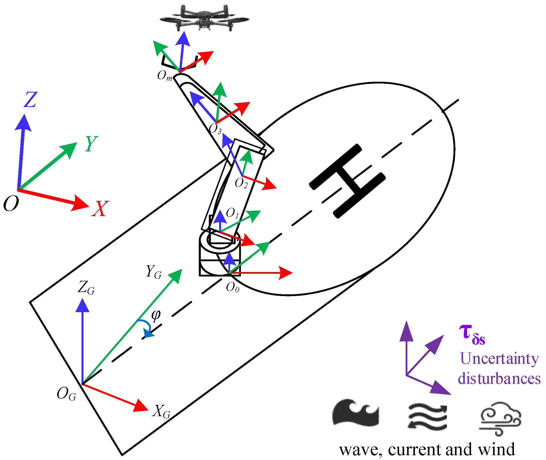
Figure 3.
Global dynamics of the shipborne manipulator.
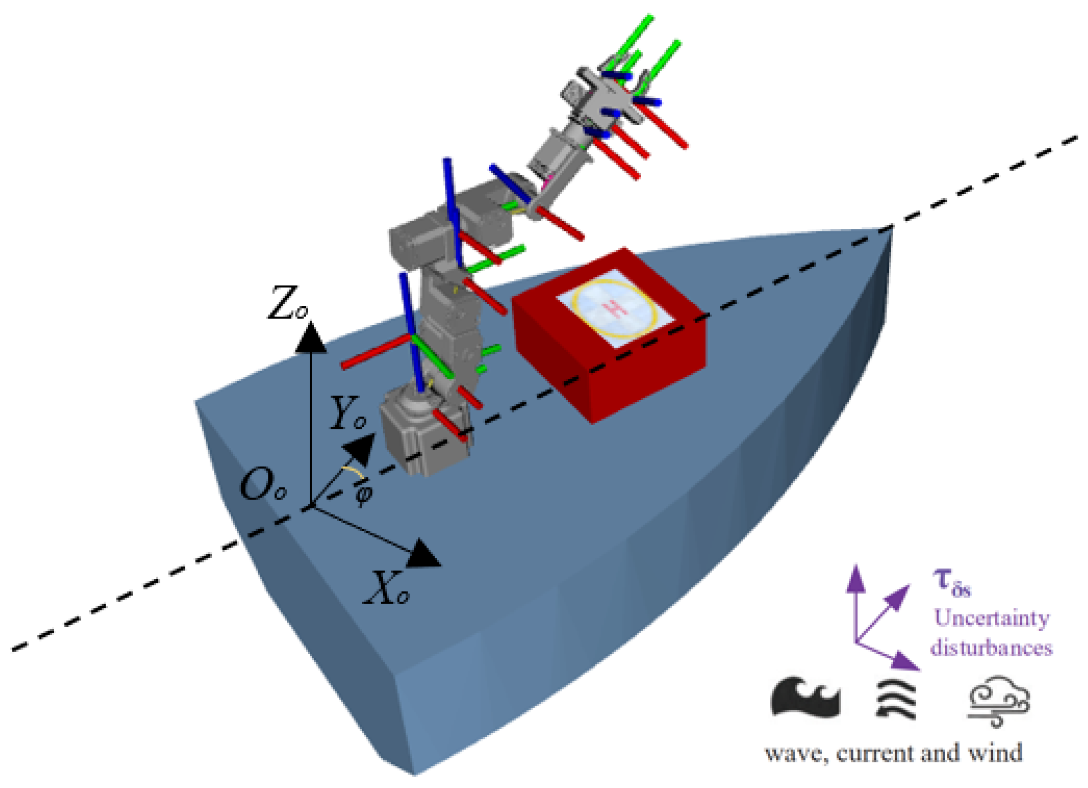
Figure 4.
The modified Denavit-Hartenberg parameters diagram of the shipbrone manipulator arm.
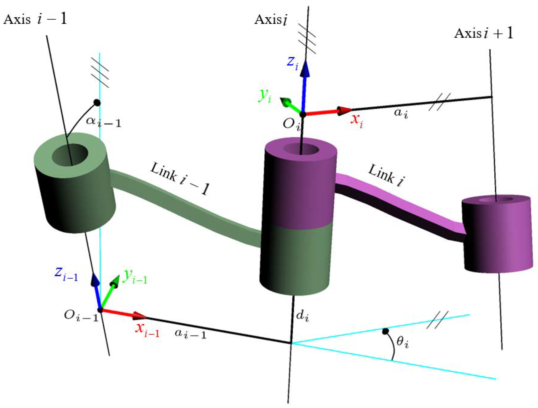
Figure 5.
The dynamics parameters diagram of the ship motion.
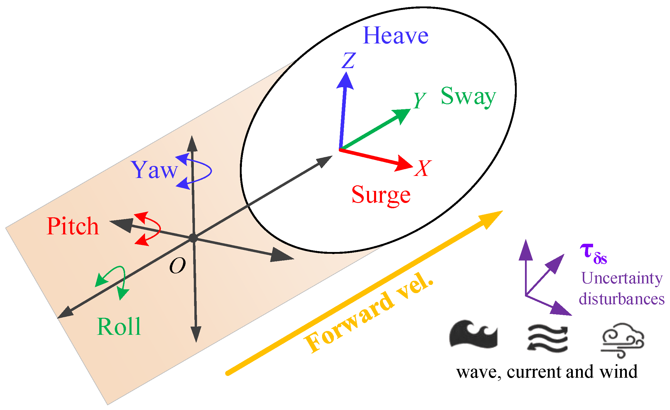
Figure 6.
The proposed grasping low-altitude drones paradigm for shipborne docking stations.
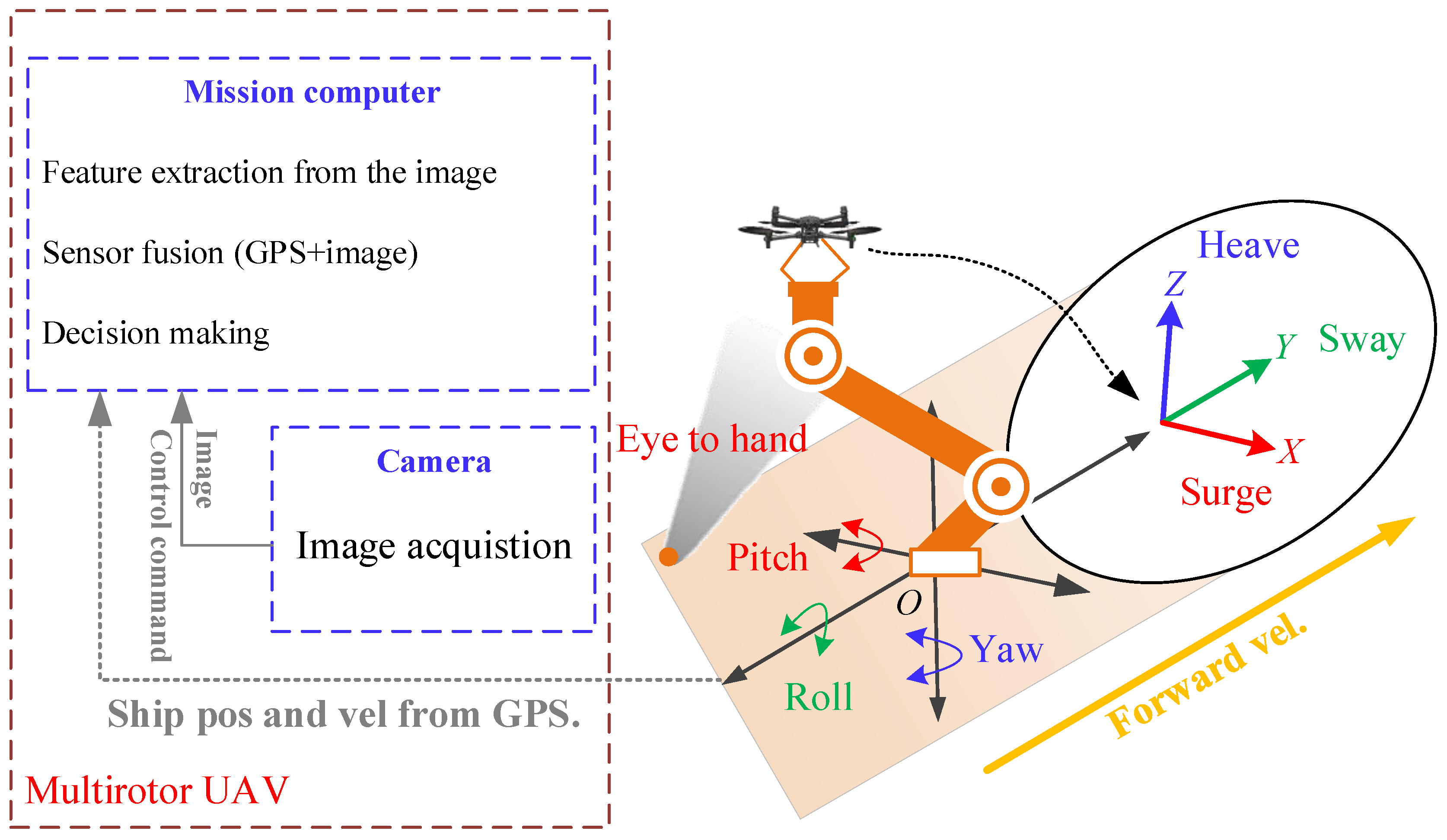
Figure 7.
The down-to-top grasping low-altitude drones docking paradigm on shipborne helistop.
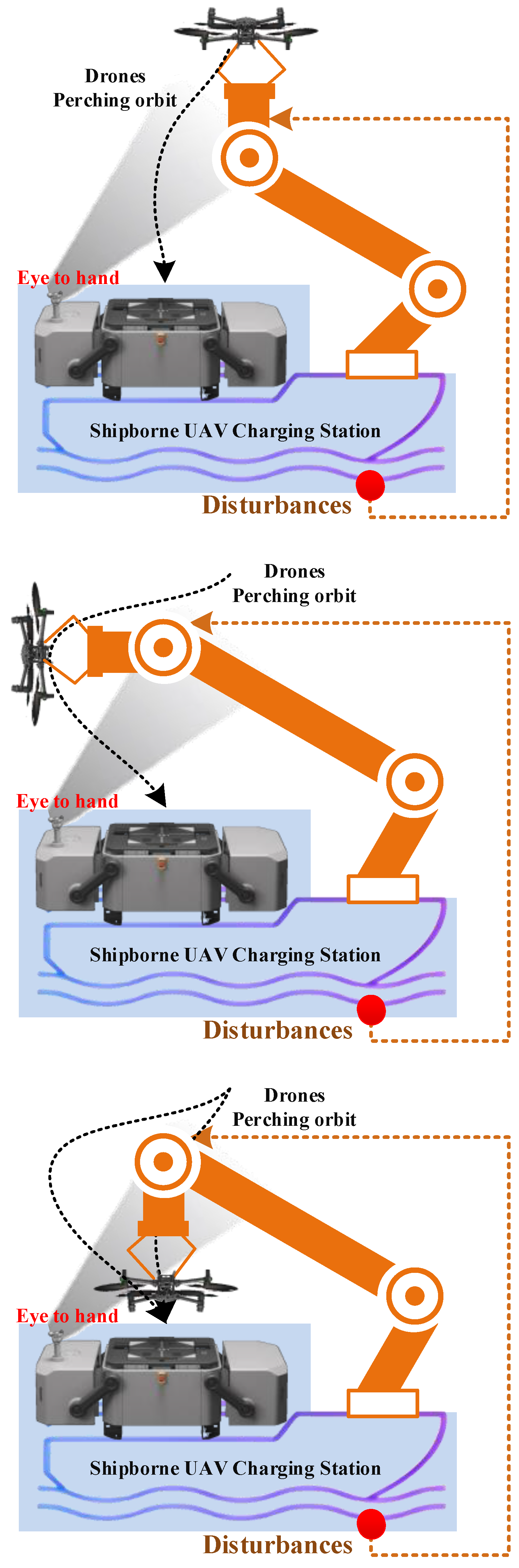
Figure 8.
The grasping low-altitude drones on the modular multi-access semi-autonomous platform.
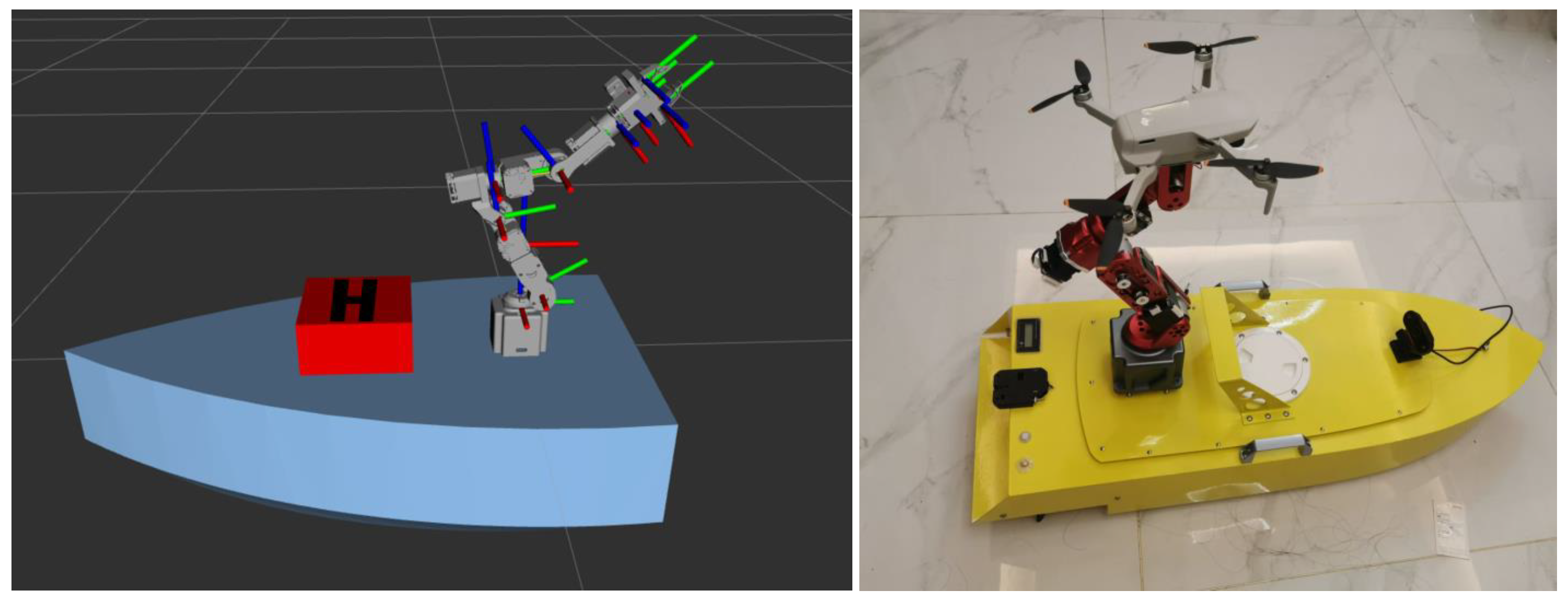
Figure 9.
The shipborne eye-to-hand classify drones within the low-altitude field.
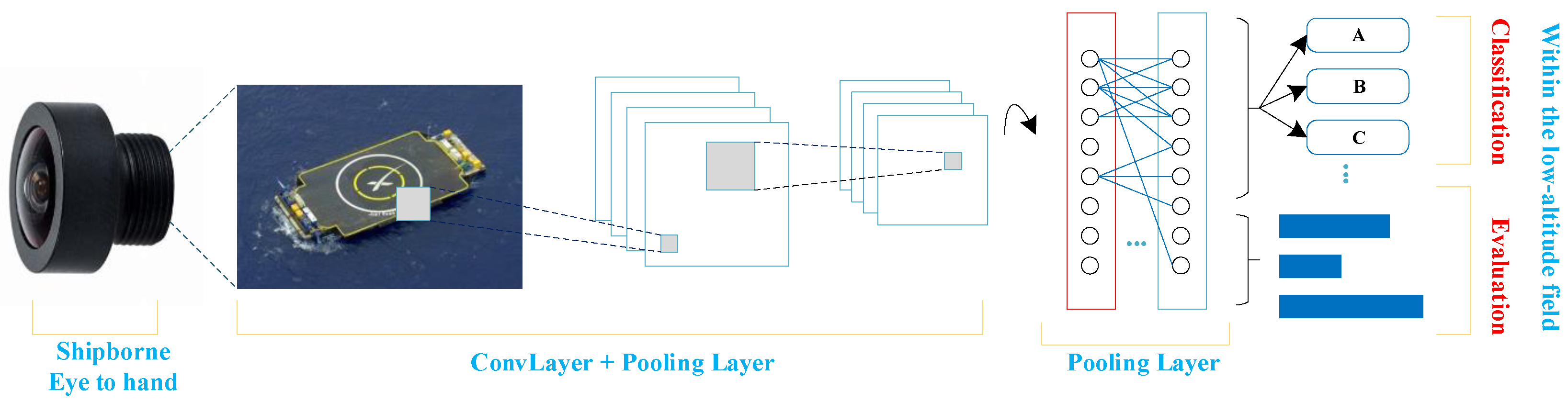
Figure 10.
The result of down-to-top grasping.
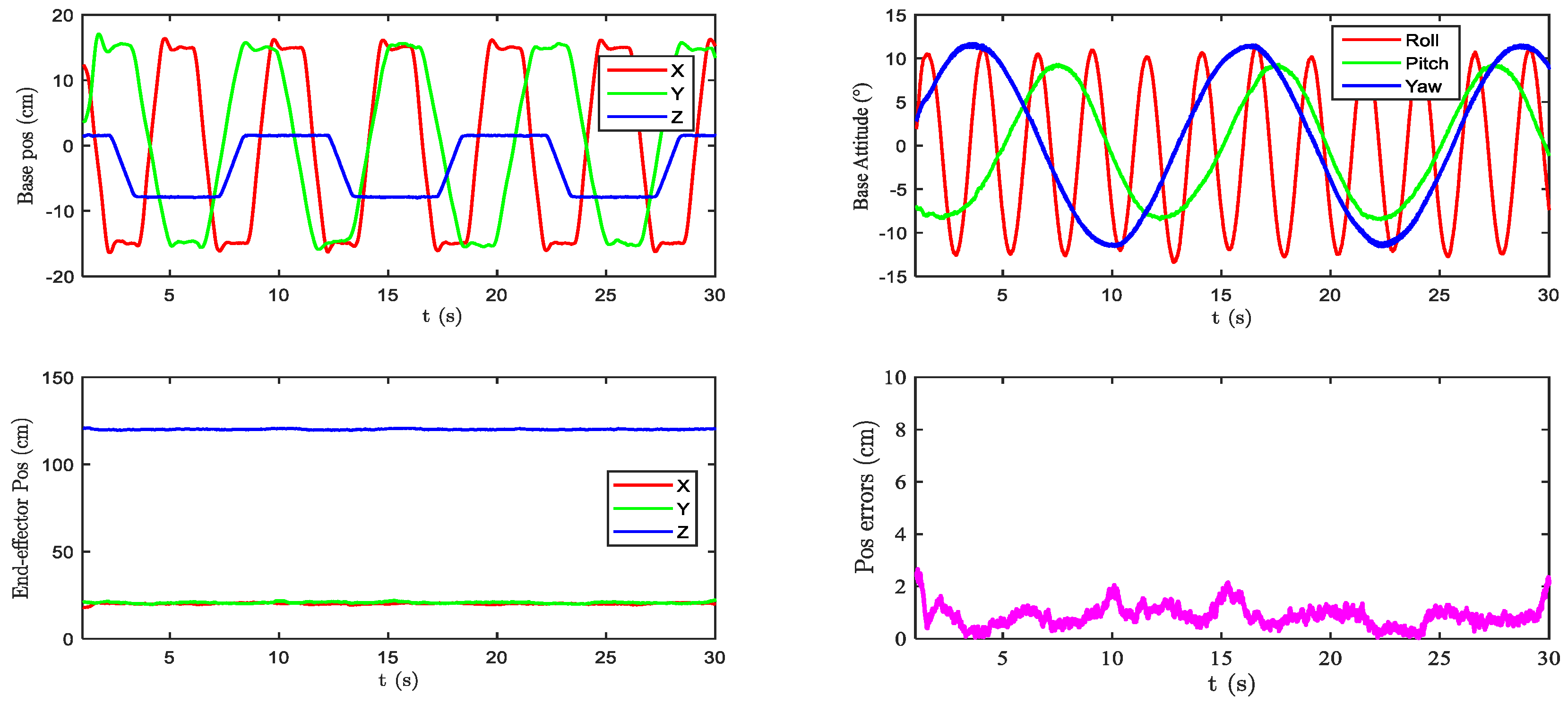

Table 1.
the parameters of shipborne grasp arm
| Notations | Values | Units |
| Degrees of freedom | 6 | |
| Grasp workspace | ||
| End-effector payload | ||
| UAV (DJI mini) weight | ||
| Camera depth range | 1.0 | |
| Ship size |
Disclaimer/Publisher’s Note: The statements, opinions and data contained in all publications are solely those of the individual author(s) and contributor(s) and not of MDPI and/or the editor(s). MDPI and/or the editor(s) disclaim responsibility for any injury to people or property resulting from any ideas, methods, instructions or products referred to in the content. |
© 2025 by the authors. Licensee MDPI, Basel, Switzerland. This article is an open access article distributed under the terms and conditions of the Creative Commons Attribution (CC BY) license (http://creativecommons.org/licenses/by/4.0/).
Copyright: This open access article is published under a Creative Commons CC BY 4.0 license, which permit the free download, distribution, and reuse, provided that the author and preprint are cited in any reuse.


