Preprint
Article

This version is not peer-reviewed.

Mechanism of Electrolytic Reduction of Coarse Boehmitic Bauxite in Alkaline Media Before Bayer Process

Submitted:

26 November 2025

Posted:

28 November 2025

You are already at the latest version

Abstract

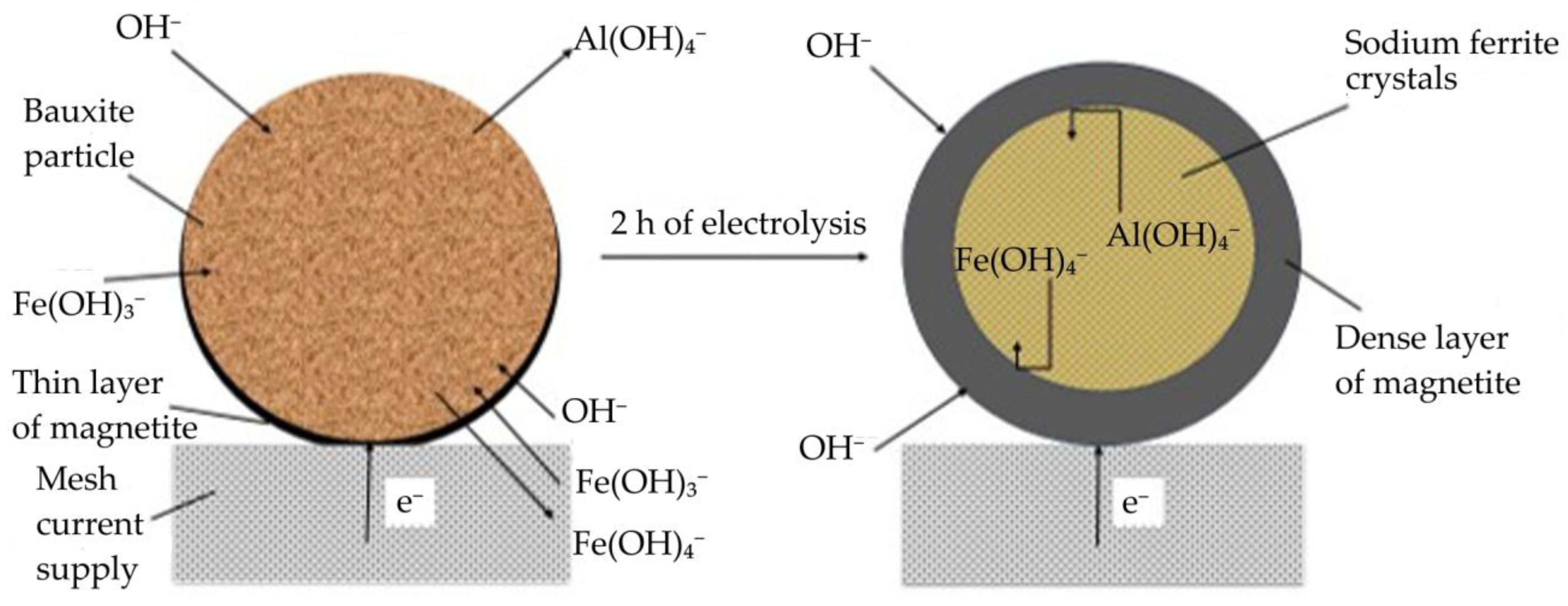
The Bayer process, the dominant method of alumina production for over a century, faces several challenges, including low iron content in bauxite residue, increased caustic alkali consumption and low alumina recovery rates. This article focuses on studying electrolytic reduction processes of bauxite iron minerals in alkaline solutions as a potential improvement to the traditional Bayer process for producing alumina. The research employs a metal mesh cathode at the bottom of an electrochemical cell to simultaneously reduce iron minerals and leach aluminium and silica from coarse boehmite bauxite before milling and high-pressure leaching. Preliminary thermodynamic research indicates that the presence of both hematite (α-Fe2O3) and chamosite ((Fe2+,Mg,Al,Fe3+)6(Si,Al)4O10(OH,O)8) in this type of bauxite helps to achieve a higher iron concentration in the solution. Cyclic voltammetry revealed that, in the initial stage of electrolysis, overvoltage at the cathode decreases as metallic iron deposited and conductive magnetite form on the surface of the particles. After 60 min, the reduction efficiency begins to decrease. The proportion of the current used for magnetization and iron deposition on the cathode decreased from 89.5% after 30 min to 67.5% after 120 min. Studying the electrolysis product using SEM-EDS revealed the formation of a dense, iron-containing reaction product on the particles' surface, preventing diffusion of the reaction products. Mössbauer spectroscopy of the high-pressure leaching product revealed that the primary iron-containing phases of bauxite residue are maghemite (Fe3O4), formed during the hydrolysis of sodium ferrite (Na2FeO4).

Keywords: 
;  ;  ;  ;  ;  

1. Introduction

The Bayer process remains the primary method for producing alumina worldwide. It was developed over 100 years ago for processing bauxite using an alkaline hydrometallurgical extraction process to obtain aluminium (Al) from high-quality raw materials containing alumina with a low silica content (where the silica modulus, or the mass ratio of Al2O3 to SiO2, is less than 7) [1,2].
During the first stage of bauxite leaching using the Bayer process, silicon (Si), along with Al, passes into the alkaline aluminate solution. The dissolved Si then reacts with aluminate ions (Al(OH)4-) to form a desilication product: sodium hydroaluminosilicate (DSP, Na6[Al6Si6O24]·Na2X, where X represents various inorganic anions, most commonly sulphate, carbonate, chloride and aluminate) [3,4].
To reduce losses of caustic alkali and prevent the formation of sodium titanate films during bauxite processing, lime is added [5,6]. This significantly increases the yield of bauxite residue (BR), but also increases Al losses [7].
The losses of caustic alkali and Al during DSP formation determine the economic efficiency of processing bauxite using the Bayer process [8]. From this perspective, bauxites with a silica modulus of less than 7, and aluminosilicate raw materials where the Al2O3/SiO2 ratio is less than 1, are more economically viable to process using the sintering method [9]. In this method, Si binds with calcium (Са) to form dicalcium silicate (Ca2SiO4) at temperatures exceeding 1100 °C [10]. This leads to a significant increase in energy costs, as well as a further increase in BR yield. High amount of BR stockpiled on ponds can have a detrimental environmental impact [11,12].
The formation of DSP and the artificial addition of lime result in:
  • reduced iron (Fe) content in BR (down to 35%);
  • increased consumption of caustic alkali (up to 100 kg/t of Al2O3);
  • low Al recovery (no more than 85–90%);
  • consequently, higher Al2O3 content in BR (up to 10–15%).
As a result, the BR produced using the current Bayer process technology is unsuitable for recovering valuable components, including Fe and rare earth elements[13,14,15], whose content in red mud is several times higher than the average value for the Earth’s crust [16].
Many recent studies have focused on reducing the amount of BR produced by obtaining high-iron slag using pyrometallurgical reduction [13,17,18] and reductive leaching [19,20].
Hydrometallurgical methods that convert iron into a magnetic phase directly during leaching show promise in terms of environmental friendliness [21]. However, these methods require the use of new reagents, which can significantly increase the cost of alumina production. The most cost-effective and environmentally friendly method for hematite reduction, which could be used in the future, is electrolytic reduction [22,23].
In our previous work, it was demonstrated that using a metal mesh cathode at the bottom of an electrochemical cell enables the simultaneous magnetization (transformation to magnetite) of iron minerals and the leaching of Al in an alkaline solution [24]. However, the reduction mechanism was not fully understood, and use of a purely alkaline solution, into which almost all Al passed, made subsequent Al recovery and filtration difficult.
In this study, the reduction of iron minerals from large bauxite particles (prior to milling) using a stainless-steel mesh cathode was investigated. This makes it easier to separate the bauxite particles from the alkali solution. The electrochemical process using a Pourbaix diagram, cyclic voltammetry and galvanostatic experiments at different times was studied. The products of the electrochemical reduction and subsequent autoclave leaching were analyzed using X-ray diffraction (XRD), X-ray fluorescence analysis (XRF), Scanning electron microscopy with energy dispersive spectroscopy (SEM-EDS), vibrating sample magnetometer (VSM) and Mössbauer spectroscopy.

2. Materials and Methods

2.1. Materials and Reagents

The raw unmilled boehmitic bauxite with an average particle size of 1-3 mm, which was used in this study, was obtained from the Middle Timan deposit in Ukhta, Russia. The main reagent used was an NaOH (analytical purity), dissolved in distilled water to obtain solutions with Na2O concentrations of 300, 400 and 550 g/L. To obtain a spent Bayer process solution, the required amount of Al(OH)3 (analytical purity) was dissolved in a 300 g/L Na2O hot NaOH solution.

2.2. Analytical Methods
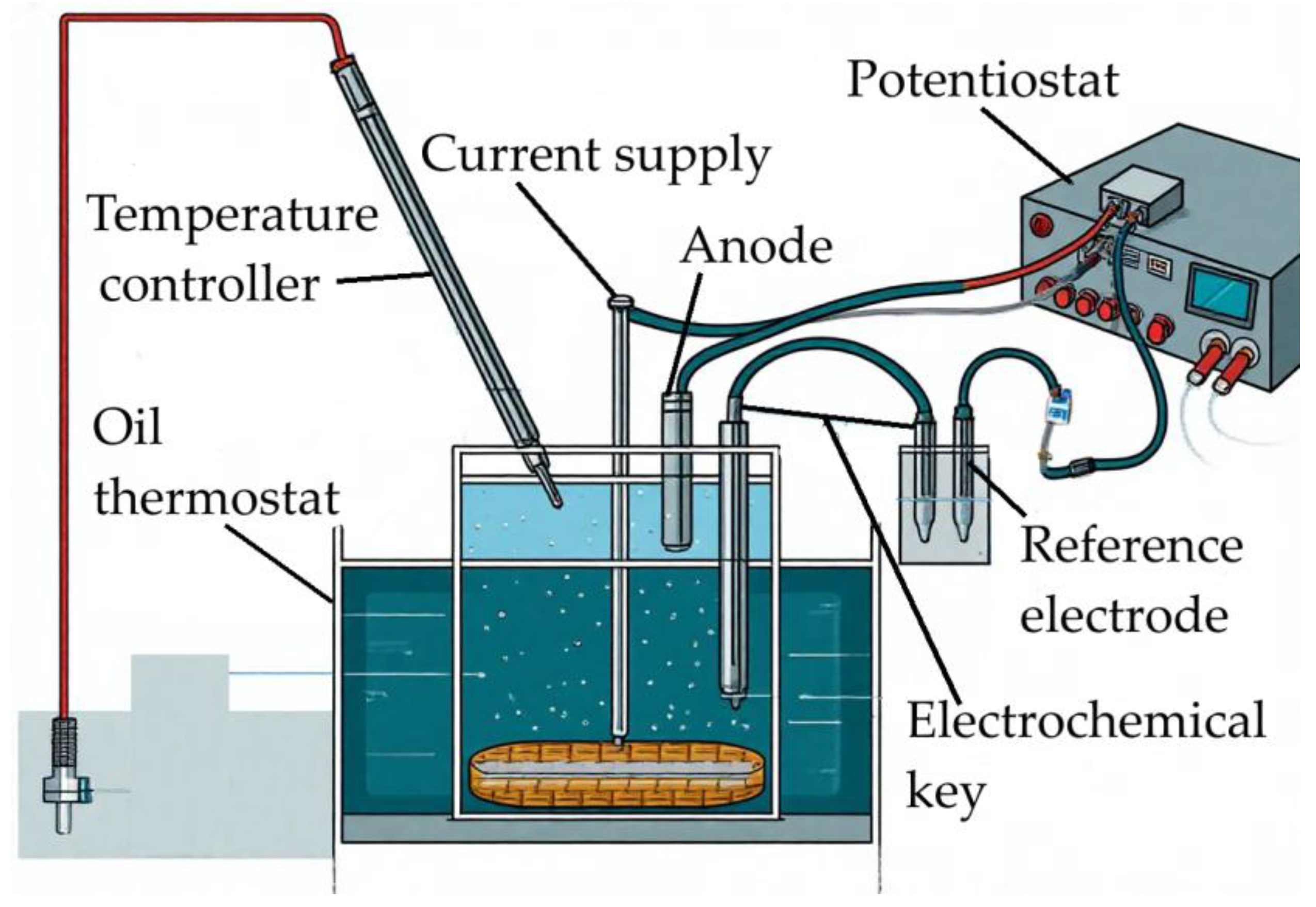
The mineralogy of the raw bauxite and the solid residue after alkaline treatment were studied using X-ray diffraction (XRD) on a Difrei-401 X-ray diffractometer (Scientific Instruments, St. Petersburg, Russia), with a Cr-Kα radiation source and a 2θ range of 15–140°, and an exposure time of 30 min. The X-ray source operating mode was set to 25 kW/4 mA. Mineral phase analysis and semi-quantitative evaluation using the Rietveld method were performed using Match! 3 (Crystal Impact, Bonn, Germany).
The chemical composition of the bauxite and the solid residue was determined using an Axios Max XRF X-ray fluorescence spectrometer (Panalytical, Almelo, Netherlands). Loss on ignition (LOI) was determined using a Diamond TG/DTA (PerkinElmer, Waltham, MA, USA) by heating a sample from 50 to 1000 °C at a rate of 20 °C per min.
SEM-EDS analysis of the electroreduction product was performed using a VEGA TESCAN 3 microscope (Tescan, Brno, Czech Republic).
The iron content in liquid media after the contact of alkaline solutions with iron monomineral was determined using ISP-OES with an Optima 2100 DV device (PerkinElmer, Waltham, MA, USA).
Vibrating sample magnetometer LakeShore 7407 (Lake Shore Cryotronics, Inc., Westerville, OH, USA) was used to determine the magnetic properties of bauxite residue.
57Fe Mössbauer absorption spectra were measured in transmission geometry with moving source and triangular velocity references signal on an express Mössbauer spectrometer MS1104EM (CJSC Kordon, Rostov-on-Don, Russia) at 296(3) K and 77.7(3) K. In this case, the source of γ-radiation in the form of 57Co in a matrix of metallic rhodium with an activity of 25 mCi (Cyclotron Co., Ltd, Obninsk, Russia) was at room temperature. The reference absorber of α-Fe foil was used for the velocity calibration. The noise/signal ratio did not exceed 2% for all spectra. Mathematical processing of the experimental Mössbauer spectra was carried out for high-resolution spectra (1024 points) using the SpectRelax 2.8 software (Lomonosov Moscow State University, Russia) [25]. Values of isomeric shifts are indicating relative to α-Fe at 296 K.

2.3. Experimental

The electrolysis experiment was conducted using a 500 ml steel reactor lined with fluoroplastic and placed in an oil bath. This setup was used to heat the pulp (consisting of 100 g of bauxite and 300 ml of an alkaline solution with a concentration of 400 g/L Na₂O) to the required temperature (Figure 1). The temperature of the pulp was controlled using a temperature controller connected to the PID regulator of the oil bath. A stainless-steel mesh (area: 110 cm2) with a stainless-steel wire lead was used as the cathode. A nickel plate (10 cm2) was used as the anode. The reference electrode was an OH-/HgO,Hg mercury oxide electrode (with a potential of 0.098 V relative to a hydrogen electrode in a 10 M KOH solution at 25 °C). The reference electrode was placed in a separate beaker on a stand outside the oil bath, which was connected to the main reactor via an electrochemical cell.
The electrochemical key and the beaker containing the reference electrode were both filled with a 10 M NaOH solution. The electrodes were then connected to the corresponding terminals of the ZiveLab SP2 potentiostat (ZiveLab, South Korea). Large bauxite particles were placed on a stainless-steel mesh cathode in a cell, and the resulting mixture was then heated to the required temperature. Once the temperature reached 120 °C, the electrolysis experiment was started for various durations: 5, 30, 60, 90 and 120 min.
The reduction product was then ground in a ball mill using a Bayer process spent solution (300 g/L Na2O and 150 g/L Al2O3) until 90% of the particles were smaller than 70 µm. The volume of the solution was selected based on a molar ratio of Na2O to Al2O3 in the pregnant solution of 1.5 units. The resulting pulp was sent for high-pressure leaching at 250 °C for one h in tightly closed 100 ml steel autoclaves placed in an air thermostat (ECROS, Russia). After the required duration, the pulp was filtered and washed with distilled water. The solid residue was sent for analysis.
To determine the equilibrium concentration of iron in solution when various iron monomineral solutions placed into contact with alkaline solutions at different temperatures and concentrations, 6 g of monomineral was placed in 10 ml of solution in a Teflon-coated steel beaker. This was then placed in an oil bath equipped with magnetic stirring and held for 12 h at predetermined temperature.
To evaluate the efficiency of electric current utilization, the magnetite content in the sludge was determined using XRD analysis, and the change in cathode mass was measured to account for the mass of elemental iron formed. Then, the proportion of current used for reduction was evaluated using the method described elsewhere [24].
Eh-pH diagrams of the Na2O-Fe-H2O system were drawn using the HSC Chemistry Software Version 6.0 (Outokumpu Research Oy, Finland).

3. Results and Discussion

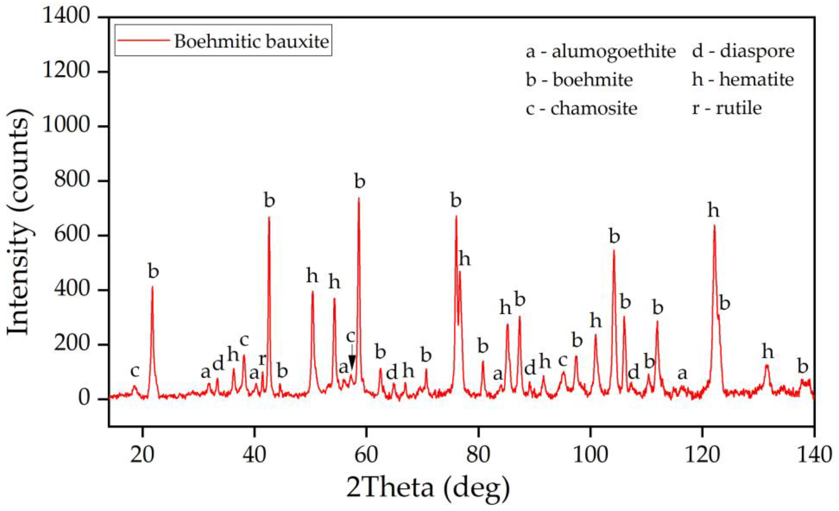
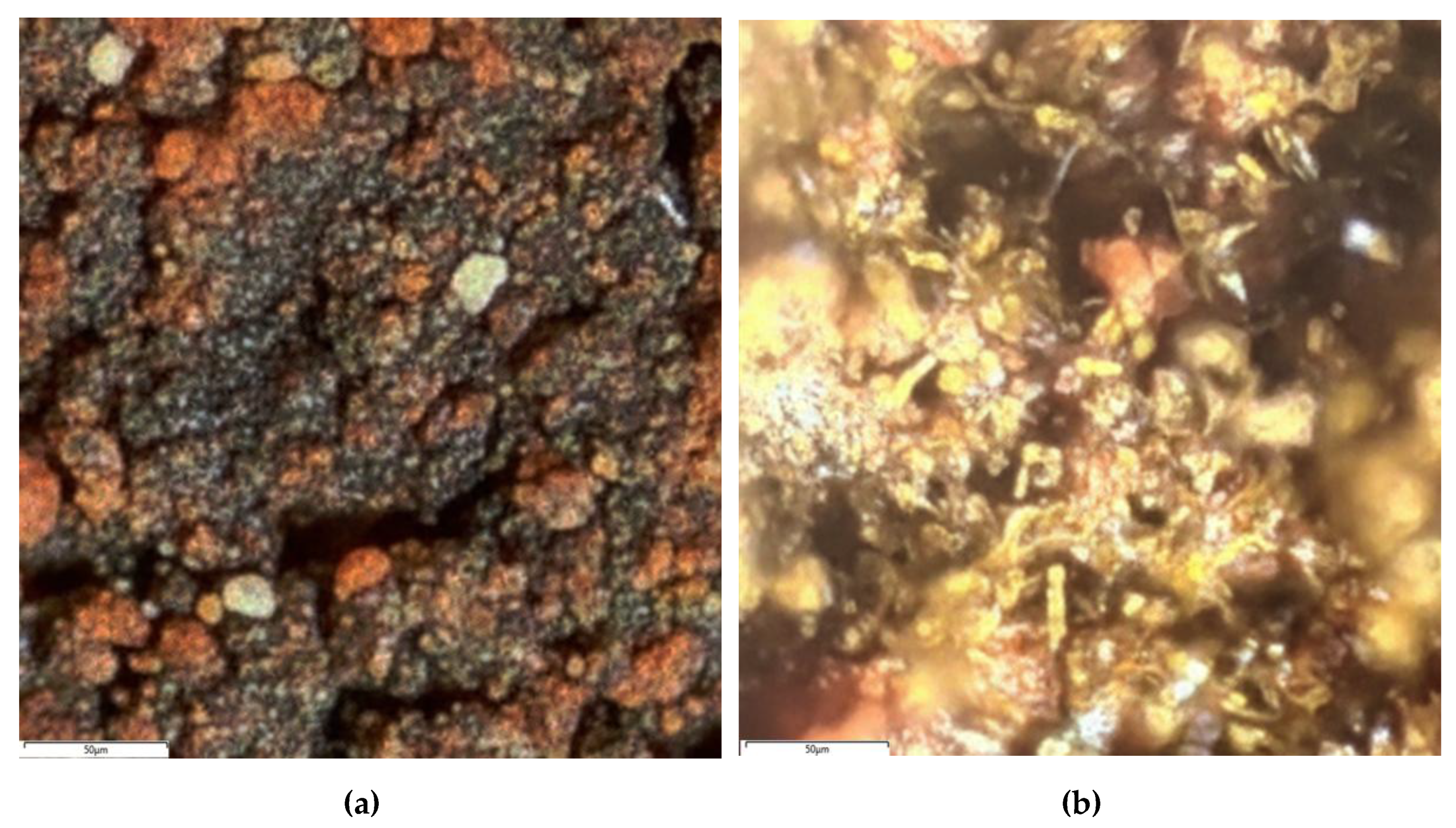
3.1. Characterization of the Raw Bauxite

Figure 2 shows an XRD pattern of the original bauxite.
The raw bauxite mainly consists of boehmite (γ-AlOOH), hematite (α-Fe2O3) and chamozite ((Fe2+,Mg,Al,Fe3+)6(Si,Al)4O10(OH,O)8). Small amounts of alumogoethite (Fe(Al)OOH), rutile (TiO2), and diaspore (α-AlOOH) are also present. Therefore, this bauxite can be classified as a boehmite-hematite-chamosite. A semi-quantitative analysis of the crystalline phases in the raw bauxite sample, determined using the Rietveld method, is shown in Table 1. According to Table 1, boehmite represents more than 62% of the bauxite, hematite represents more than 25%, and the remainder is made up of alumogoethite, rutile, and chamosite. However, it should be noted that chamosite also contains clay and silica, which can lead to subsequent problems during leaching (secondary Al losses due to the formation of DSP). Additionally, according to literature data [26], kaolinite is often present in high-silica bauxites; however, its presence in this bauxite sample is either insignificant or masked by other crystalline compounds.
The data obtained are in good agreement with the results of the XRF study of the chemical composition of bauxite (Table 2).
This bauxite can be characterized as high-iron and high-silica, with a µSi of approximately 7. According to the Bayer process, this suggests low economic efficiency of using this bauxite. This is due to either the formation of a large amount of DSP during the leaching process, or the need to use a large amount of lime to bind Si.
The Mössbauer spectra of the raw bauxite (Figure 3, a and b) consist of a set of similar-width resonance lines of varying intensity which clearly belong to a sextet. In the inner part of this sextet, there is an intense doublet with significant quadrupole splitting. The low-temperature spectrum simultaneously shows ’shoulders’ on the first and sixth resonance lines of the sextet, indicating the presence of multiple ferromagnetic components in the material.
All Mössbauer spectra can be satisfactorily described by consistently compatible models containing three symmetric sextets and two symmetric doublets, depending on temperature (Table 3). At the same time, good agreement with experimental data was achieved for high-temperature spectra only if the profile of one or two inner sextets was set within the many-state superparamagnetic relaxation model [27,28,29]. Furthermore, within the framework of models for individual samples, relaxation spectra were constrained by a single relaxation time and the ratio of magnetic particle anisotropy energy to thermal energy (Equation 1) [30,31].
α = K V / kB T,
where K is the magnetic anisotropy constant, V is the volume of the magnetic domain, kB is the Boltzmann constant, T is the temperature. In the case of low-temperature spectra, it is evident that the deformation of the spectrum profile due to relaxation phenomena was minimal. This allowed subspectra with only a pseudo-Voigt function profile to be used for the model description.
Despite the fact that relaxation effects were taken into account in this work, the attribution of individual model components to possible compounds of the bauxite is fully consistent with the data described earlier [32]. Thus, the first two subspectra with the highest effective magnetic field values (see Table 3) correspond to alumina-substituted hematite [33,34], as confirmed by the absence of the Morrin transition, which is characteristic of unsubstituted hematite [30,35], within the studied temperature range. To eliminate systematic deviations in the dispersion spectrum, for example in regions 2 and 5 of the resonance lines in Figure 3a [32], in this work we took into account corrections for the second-order perturbation of the Zeeman levels by the distribution of electric field gradients a+/a-, which are characteristic of amorphous magnets similar to [36]. The corresponding corrections in the present study were −0.025(5) and −0.011(2) mm/s at 296 K and −0.031(3) and 0.0162(15) mm/s at 78 K. The internal sextet, which has a strong temperature dependence of the hyperfine parameters and is described by a relaxation spectrum at room temperature, corresponds to iron atoms in the alumogoethite structure [32]. The paramagnetic part of the spectrum can be described using two doublets corresponding to Fe atoms with charges of +2 and +3 (Table 3, subspectra 4 and 5 respectively) in an octahedral oxygen environment. We previously attributed subspectrum 4 (Table 3) to chamosite [32]. The strong temperature dependence of the intensity of subspectrum 5 (Table 3) suggests that it contains some superparamagnetic alumogoethite. The remainder of this subspectrum may be attributed to a layered aluminosilicate such as kaolinite [37].
Thus, based on XRD and Mössbauer spectroscopy, the main iron-containing phases of bauxite were found to be hematite, alumogoethite, alumohematite and chamosite. Clearly, the efficiency of the electrochemical reduction of these minerals will differ, primarily due to their differing solubility in an alkaline solution.

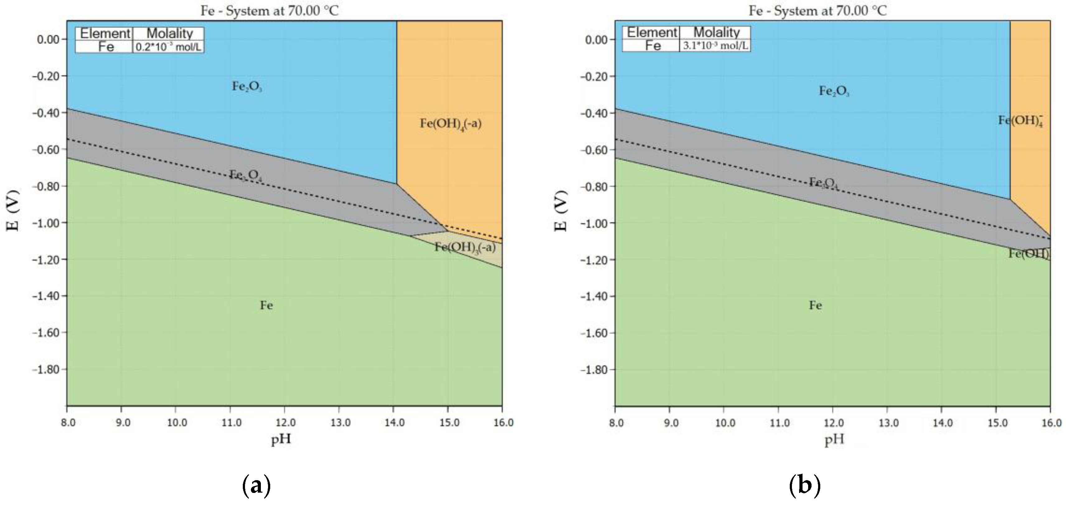
3.2. Thermodynamic Study of Iron Minerals Dissolution in Alkali Solution

The study examined the thermodynamic patterns of the dissolution of various iron minerals contained within boehmite bauxite in caustic alkali solutions with Na2O concentrations of 300, 400 and 550 g/L. Commercial monomineral samples of hematite, goethite and chamosite were used for this series of experiments. After grinding to a size where 80% of the particles were less than 73 μm, the samples were leached in caustic alkali solutions of various concentrations until equilibrium was reached (12 h). Increases in temperature and caustic alkali concentration were found to significantly increase the iron content in the alkaline solution – from 0.2 to 3.1×10⁻³ M. At the same time, the iron concentration in the solution upon contact with chamosite is higher than with hematite and goethite (Table 4). This is due to the presence of iron in these minerals in a +2 oxidation state, since Fe(OH)4 and Fe(OH)3 anions can then coexist in the solution. Despite its hydroxide nature, the iron concentration in the solution is lower for goethite than for other compounds. This phenomenon can be explained by the higher degree of iron oxidation. The hematite mineral contained a certain proportion of a magnetic fraction, which can be attributed to magnetite, leading to a higher iron concentration in the solution. Accordingly, using alkaline solutions that do not contain Al and using raw materials that contain iron compounds with an oxidation state of 2+ allows for a significant increase in the iron content of the solution.
It should be noted that, even in industrial solutions used in the Bayer process — where an alkaline-aluminate solution is employed instead of a pure alkaline one — the iron content is higher after leaching when processing bauxite containing iron in the +2 oxidation state. At the RUSAL Krasnoturinsk plant (Krasnoturinsk, Russia), which processes bauxite containing soluble pyrite, the iron concentration in the aluminate solution is 0.2×10⁻³ M, or approximately 10 mg/L. In contrast, at the RUSAL Kamensk-Uralsky plant (Kamensk-Uralsky, Russia), which processes bauxite containing refractory chamosite from the Middle Timan deposit, the iron concentration in the aluminate solution is typically less than 0.1×10⁻³ M. Therefore, using pure alkaline solutions and processing raw materials containing iron compounds with an oxidation state of +2 allows for a significant increase in iron content in the solution.
Pourbaix diagrams showing the thermodynamically stable phases in the system at various concentrations of alkali solution and redox potentials were constructed using the HSC Chemistry software package (Figure 4). An increase in the concentration of caustic alkali was found to shift the equilibrium towards complex iron anions. Conversely, an increase in iron concentration leads to an increase in the stability zone of Fe3O4 and Fe2O3. Consequently, the higher the iron content in the solution, the more concentrated the Na2O solution should be for the mineral to dissolve easily. At a potential below –0.9 V, magnetite and Fe(OH)3 are stable compounds. As the concentration of caustic alkali increases, the region in which these phases exist shifts towards lower potentials. Below a potential of –1.2 V, elemental iron becomes the stable phase.
The obtained data indicate the fundamental possibility of obtaining iron compounds containing magnetite and elemental iron through electroreduction in an alkaline solution. They also allow the selection of conditions conducive to obtaining a particular phase.

3.3. Electrochemical Studies of Iron Minerals Reduction in Suspension of Coarse Bauxite Particles in Alkali Solution

Cyclic voltametric (CV) measurements were carried out at a temperature of 120 °C, a solid to liquid (S:L) ratio of 1:3, a scanning rate of 10 mV/s and a mesh current supply area of 110 cm2 after 300 s of electrolysis at a constant potential of −1.35 V (Figure 5), in order to evaluate the potential at the cathode during the electrolytic reduction of iron oxide in a suspension of unground bauxite in an alkaline solution. This process is necessary in order to obtain magnetite and elemental iron in the product.
According to Figure 5, three anodic peaks and two cathodic peaks were observed. Current C1, which has a potential of ~–0.9 V and is caused by the formation of Fe²⁺ compounds [38], is difficult to distinguish under these conditions. The C2 current at E = –1.19 V, which can be attributed to the reduction of iron compounds to Fe [39], is only visible as a shoulder since, at cathode potentials below –1.2 V, the hydrogen evolution side reaction becomes dominant. Peak A3, which is visible as a shoulder at a potential of –0.45 V, is attributed to the oxidation of Fe particles, passivated by Fe3+ compounds [39]. Peaks A2 and A3 refer to the oxidation of Fe2+ species, in the range of current C1.
Figure 6 shows the results of CV under the same parameters after 1800 s of electrolysis. Unlike the voltammetry curve in Figure 5, a higher current is achieved at the same potential after 1800 s of electrolysis (i.e. the current density increases) and there is less overvoltage at the cathode. The C1 peak, which is responsible for the formation of Fe²⁺ compounds, also becomes clearly visible. Additionally, the C2 peak, responsible for the formation of Fe, is visible up to a potential of –1.2 V, though it becomes indistinguishable. Anodic peaks not affected by hydrogen evolution remain distinct.
CV confirmed the formation of Fe2+ and Fe compounds when a mesh cathode and large bauxite particles were used. To obtain metallic Fe, the current should be selected so that the cathode potential is approximately –1.2 V. During electrolysis, this potential may increase due to a decrease in overvoltage. Using a suspension of large bauxite particles in an alkaline solution with a concentration of 400 g/L and a current collector area of 110 cm2, this potential was achieved with a constant current of 2 A and a S:L ratio 1:3 (Figure 7).
Initially, an increase in the potential at the cathode was observed, which can be explained by the deterioration of the contact between the bauxite particles and the current supply due to the evolution of hydrogen. After 50 min of electrolysis, the cathode potential increased to –1.167 V, which can be attributed to an increase in the cathode area resulting from the deposition of iron on the current supply and the compaction of the bauxite particles on the metal mesh surface. Similar results were obtained in our previous studies using a mesh cathode [24]. After 70 min of electrolysis, the potential began to decrease again, possibly due to completion of the reduction process.
Impedance measurements in work [39] showed that, during the electrochemical reduction of iron minerals in an alkaline solution, resistance to charge transfer decreases by 3–5 times compared to initial values. This is due to an increase in the cathode area caused by the formation of reduction products on its surface and the reduction of all adjacent iron mineral particles. An increase in the double layer capacity was also observed after reduction, indicating an increase in the surface area of the samples.
The increase in the area of the electrochemically active surface, and consequently the capacity, is consistent with the increase in current density during cyclic measurements (Figure 5 and Figure 6) and the decrease in cathode polarization during galvanostatic measurements (Figure 7).
Figure 8 illustrates the impact of electrolysis duration on electric current utilization efficiency, current yield for iron deposition on the cathode only, and iron mineral magnetization degree when employing a bulk cathode, a S:L ratio 1:3, a 120 °C temperature, and a 2 A constant current.
Figure 8 shows that, as the reaction proceeds, the efficiency with which electrical current is utilized decreases steadily. After 120 min of electrolysis, the magnetization level reached 65.5%, with 0.5 g of elemental iron deposited on the cathode. This amount of iron consumed 23.9% of the current. During 2 h, the proportion of current used for magnetization and iron deposition on the cathode decreased from 89.5% after 30 min to 67.5% after 120 minutes. The increase in overvoltage at the cathode after 50 min of electrolysis (see Figure 7) and the subsequent decrease in electric current utilization efficiency suggest that electrolysis efficiency is low in the later stages. Studies were conducted on the solid phase that formed after electrolysis and the residue of its high-pressure leaching to determine the mechanism of inhibition.

3.4. Solid Products Characterization

In order to study the reduction mechanism, the causes of the slowdown in later stages and the decrease in electric current utilization efficiency, examination of the solid residues obtained after reduction was conducted. Figure 9 shows photographs taken with an optical microscope of large particles of the reduction product. Figure 9a shows the surface of a particle and Figure 9b shows its interior. Magnetization is evident on the surface, and the green color inside the particle may indicate the presence of sodium ferrite. It is therefore possible that caustic alkali is trapped inside the particle, unable to diffuse out.
An SEM-EDS analysis of the particle section was performed (Figure 10). The outer surface was found to be covered with a reduction product containing high levels of iron, while Al and Na were concentrated inside the particle. Based on these results, a mechanism for slowing down the process by forming the product film on the particles surface is proposed (Figure 11). The sodium ferrite formation process is illustrated by equation (2):
Fe2O3 + 2NaOH = 2NaFeO2 + H2O.
Table 5 shows the results of analyzing the chemical composition of the solid residue after 2 h of electrolysis at a constant current of 2 A, a temperature of 120 °C and a S:L ratio of 1:3 in a 400 g/L Na2O alkaline solution.
Subsequently, the resulting reduction product was ground in a Bayer spent solution and sent for high-pressure leaching. Figure 12 shows the X-ray diffraction patterns of the electrolysis product after 2 h and the solid residue from high-pressure leaching. As can be seen, after electrolysis and autoclave leaching, the iron minerals of the original bauxite are enriched with magnetite (maghemite). Following Al extraction, the iron content increases significantly (Table 5).
After high-pressure leaching, it was found that the proportion of the magnetic phase in the solid residue increases compared to the reduction product. This finding was confirmed by studying the magnetic properties of the samples (Figure 13). Mössbauer spectroscopy was used to analyze solid residue from the leaching of reduction product.
After bauxite reduction, its spectra at both temperatures undergo significant transformations. First, the resonance lines corresponding to the "large quadrupole splitting doublet" mentioned for the original bauxite are not observed in the BR sample (Fig. 3, c, d). Furthermore, the shape of the "sextet" resonance lines is distorted, increasing in width toward the inner part of the spectrum and splitting into individual peaks (Fig. 3, c, d) even at room temperature.
Models proposed to describe the Mössbauer spectra of the BR sample (obtained by reducing the initial bauxite) indicate significant changes in the sample’s composition. Thus, the paramagnetic part of the spectrum is represented by only a low-intensity doublet, which corresponds to Fe³⁺ atoms in a tetrahedral oxygen environment. The hyperfine parameters of subspectrum 1 (Table 3, BR sample) suggest the formation of well-crystallised hematite. Subspectrum 2 is clearly quite resistant to temperature changes and may correspond to a partially substituted maghemite phase [40,41,42]. Subspectrum 3 can also be attributed to this phase, which, together with subspectrum 4 of substituted alumogoethite, can be described using a relaxation model, as described above. Since a significant increase in isomeric shift is observed in subspectra 3 and 4 when the temperature decreases to the boiling point of nitrogen, indicating a decrease in the formal degree of iron oxidation in the compounds, it can be assumed that iron atoms in these compounds are partially replaced by Al and other transition metals (e.g. Mg, Ti).
Thus, the presence of maghemite in the product of high-pressure leaching was revealed. This phenomenon can be explained by previous studies on the sintering of iron containing materials with alkali [43]. After leaching sodium ferrite in an aluminate solution, maghemite formation was observed according to Equation 3. Consequently, magnetization of the samples occurs less due to interaction of elemental iron (which mainly remains on the cathode) with the alkaline solution and more due to hydrolysis of sodium ferrite inside the particles after electro-reduction. Maghemite can also be formed through the oxidation of magnetite. However, this phenomenon was not observed previously when finely ground bauxite was used [24]. Therefore, further research is required to understand the prevailing mechanism.
2NaFeO2 + H2O = γ-Fe2O3 + 2NaOH.
In addition to the bauxite with reduced iron minerals, metallic iron is deposited on the mesh cathode during electrolysis. As shown in the previous section, the mass of the cathode increased by 0.5 g over a period of 2 h. This indicates that 23.9% of the current was used for iron deposition and that 2.67% of the iron was recovered from the bauxite. Figure 14 shows SEM images of the iron deposited on the cathode.
It can be seen that it has a predominantly dendritic structure. It can be concluded, that these dendrites formed through the reduction of Fe(OH)₃ from the solution. Figure 15 shows the Mössbauer spectrum of an iron sample separated from the cathode mesh.
The Mössbauer spectrum of the cathode iron sample obtained at room temperature is a typical sextet (Figure 15), with hyperfine parameters (δ = 0.0026 ± 0.0006 mm/s, ε = 0.0014 ± 0.0006 mm/s and Heff = 329.51 ± 0.04 kOe), which are characteristic of metallic α-Fe [44,45,46]. The good agreement between the model and the experimental data (ascertained by the χ² value and difference spectrum analysis), and the absence of broadening of the resonance lines or changes in their shape, enables to assert the absence of dissolved metallic [47,48,49] or non-metallic [50,51,52] impurities in the material. Thus, according to Mössbauer spectroscopic data, it can be concluded that the cathode iron sample contains high-purity α-Fe.
This iron can also be used to increase the degree of magnetization of BR during the high-pressure leaching process [53].

4. Conclusions

This study investigated the electrochemical reduction of iron minerals of large, unmilled bauxite particles. The effect of electrolysis on the phase and chemical composition of products after high-pressure leaching of bauxite was examined. The study presents the following key findings:
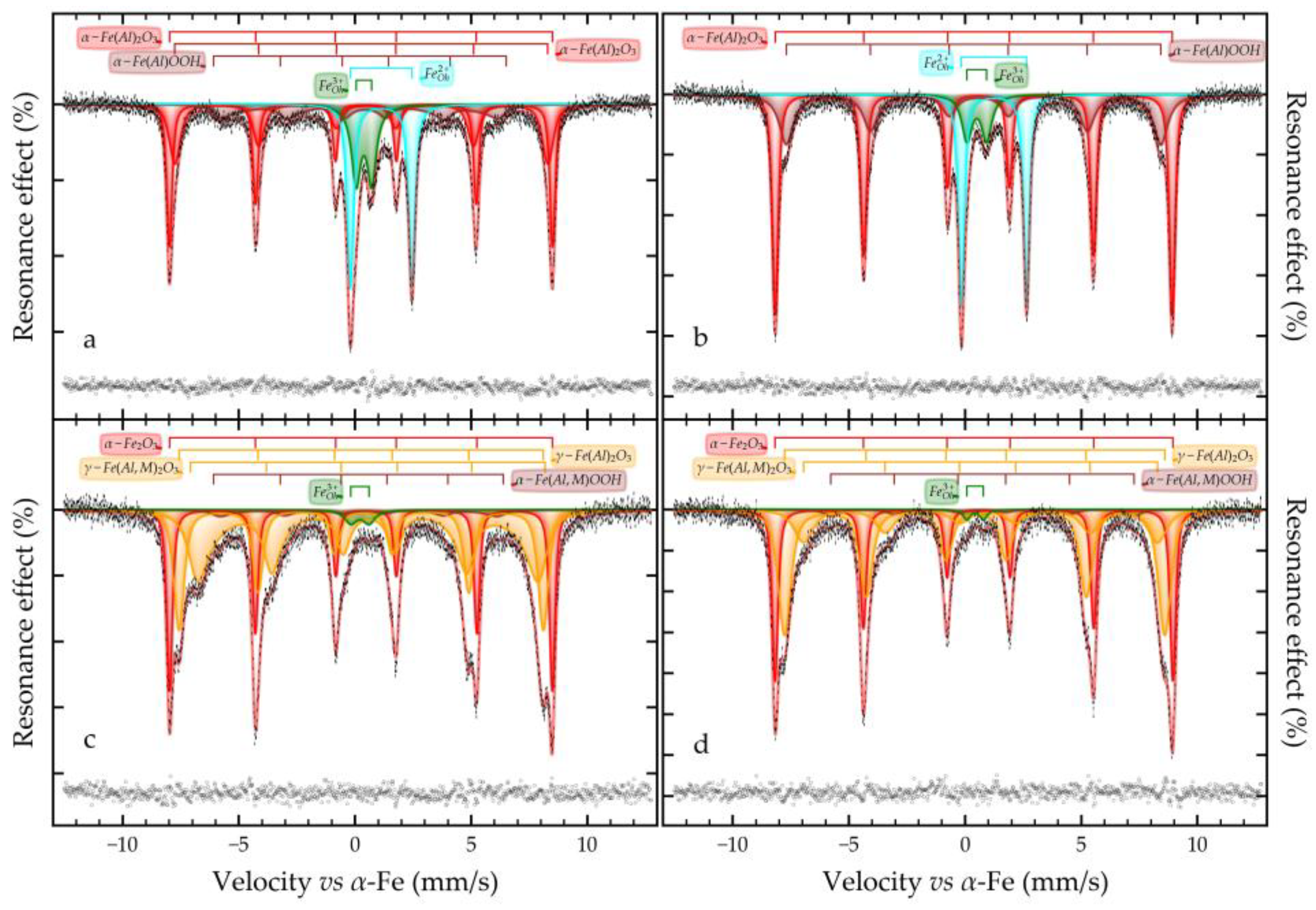
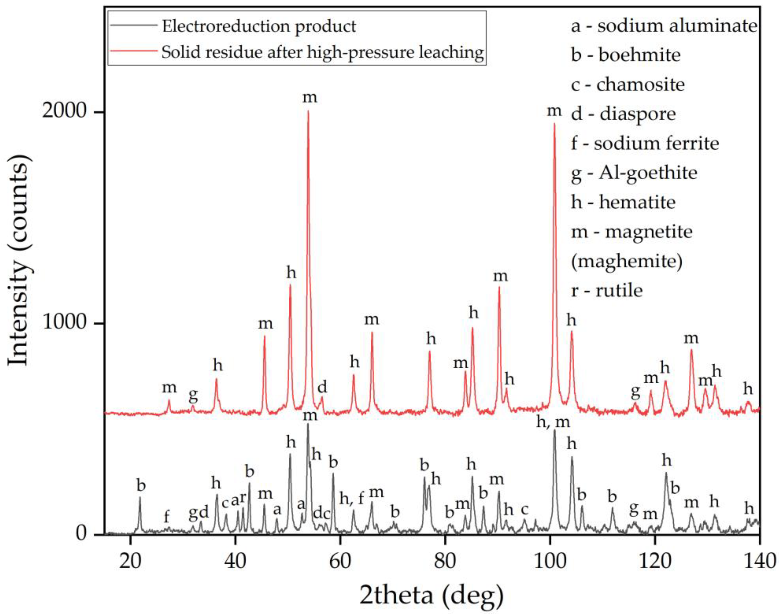
  • According to Mössbauer and XRD studies, the raw bauxite composition includes hematite, alumohematite, alumogoethite and chamosite.
  • Preliminary thermodynamic studies have shown that the highest iron concentration in solution can be achieved when an alkaline solution comes into contact with chamosite (up to 3.1×10⁻³ M). An increase in iron concentration shifts the zone of complex anion existence to a strongly alkaline environment.
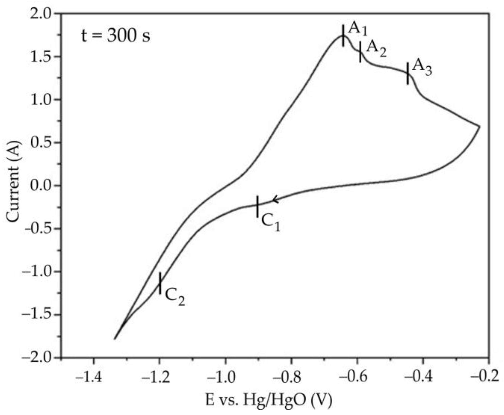
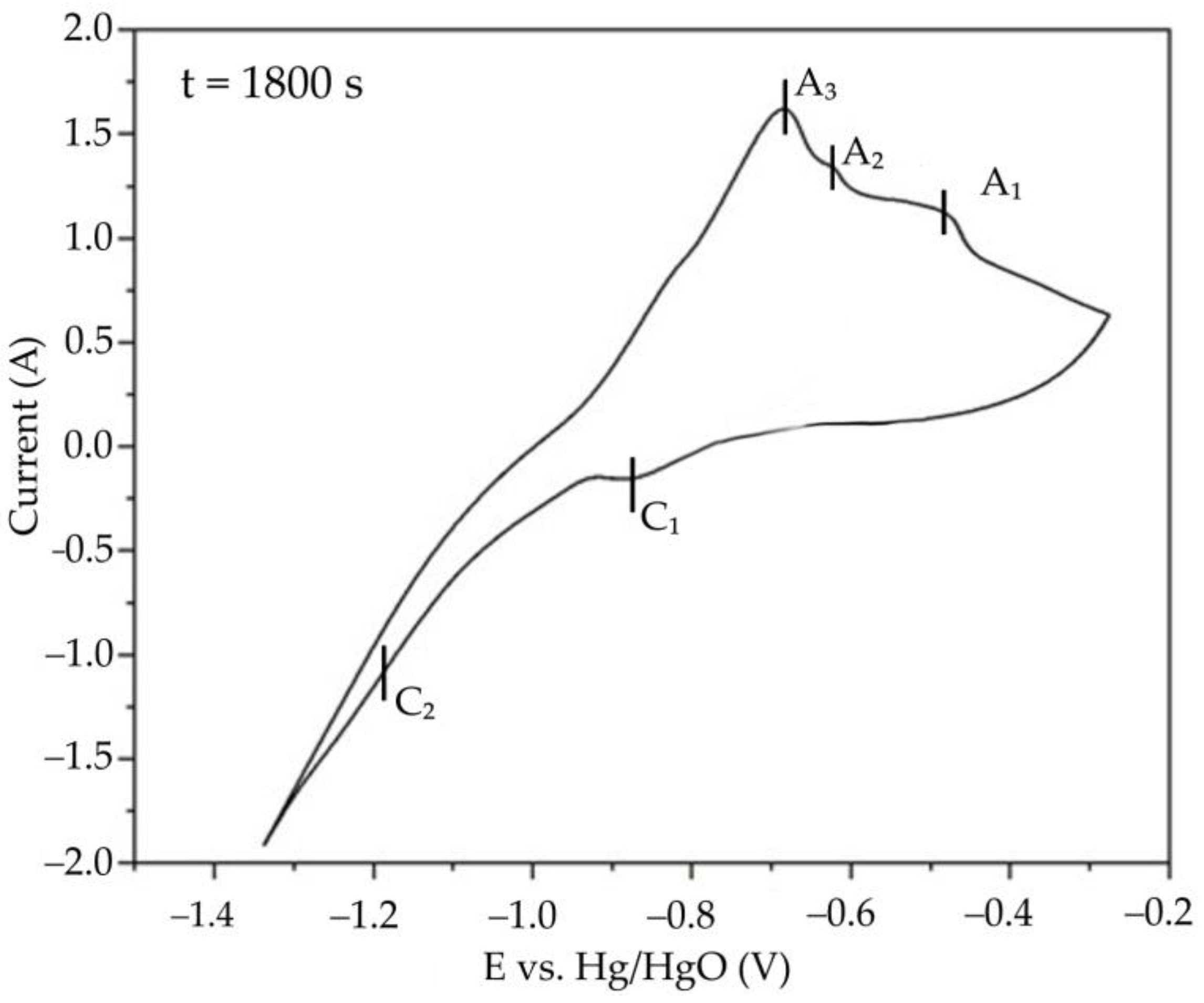
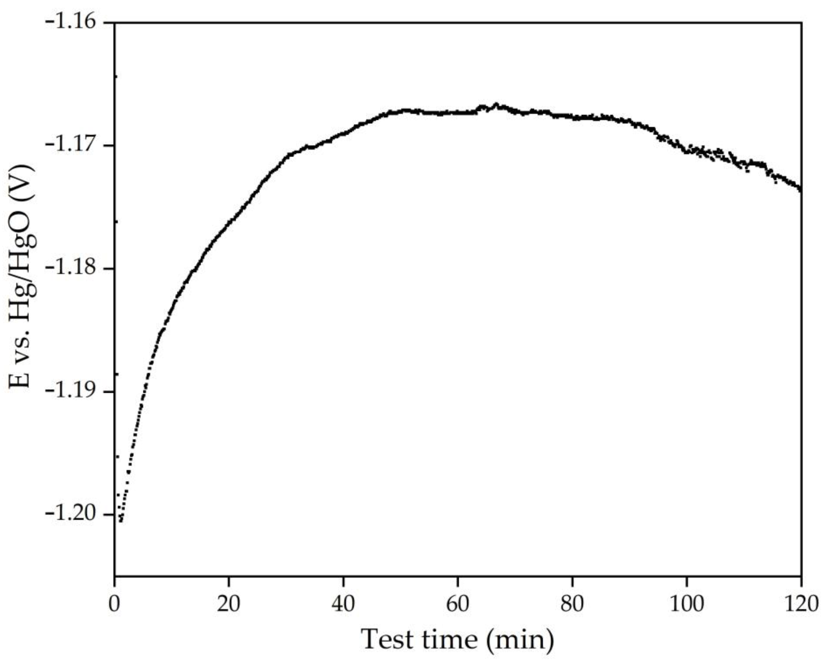
  • Cyclic voltammetry showed that, during the initial stage of electrolysis, overvoltage at the cathode decreases due to the formation of metallic iron and conductive magnetite on the surface of the electrode. After 50–60 min of electrolysis, the overvoltage begins to increase.
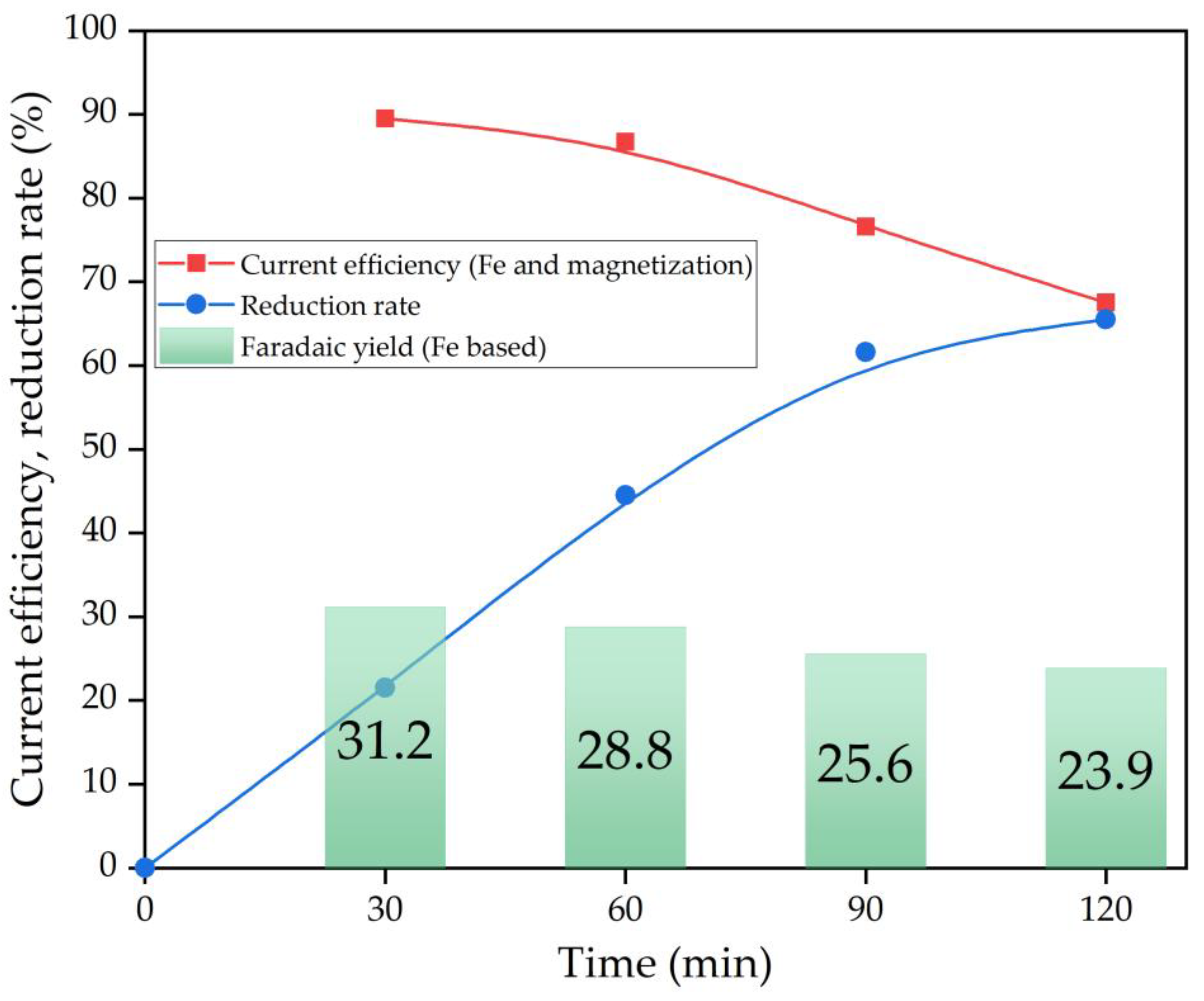
  • After 60 min of electrolysis, the reduction efficiency also begins to decrease. The proportion of the current used for magnetization and iron deposition on the cathode decreased from 89.5% after 30 min to 67.5% (23.9% of which was used for iron deposition) after 120 min.
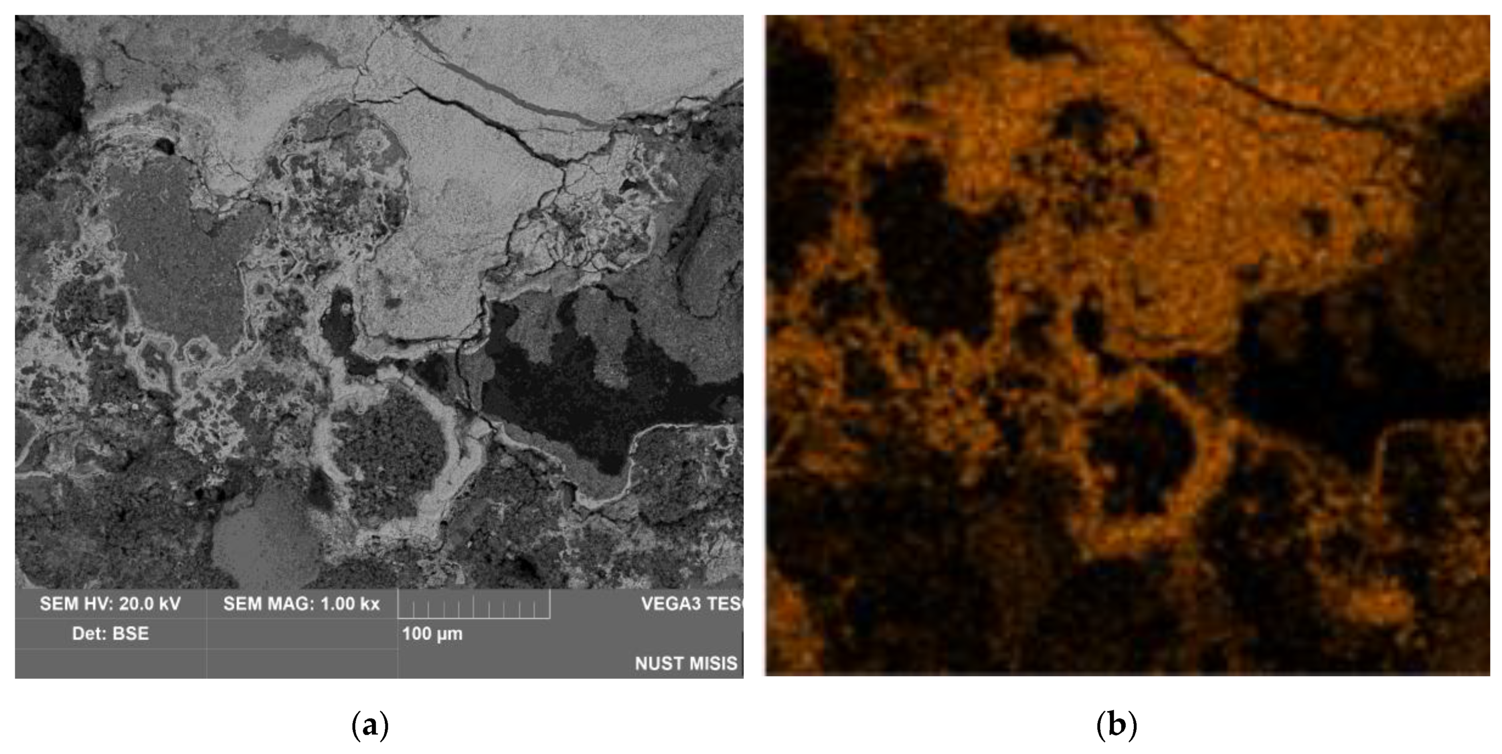
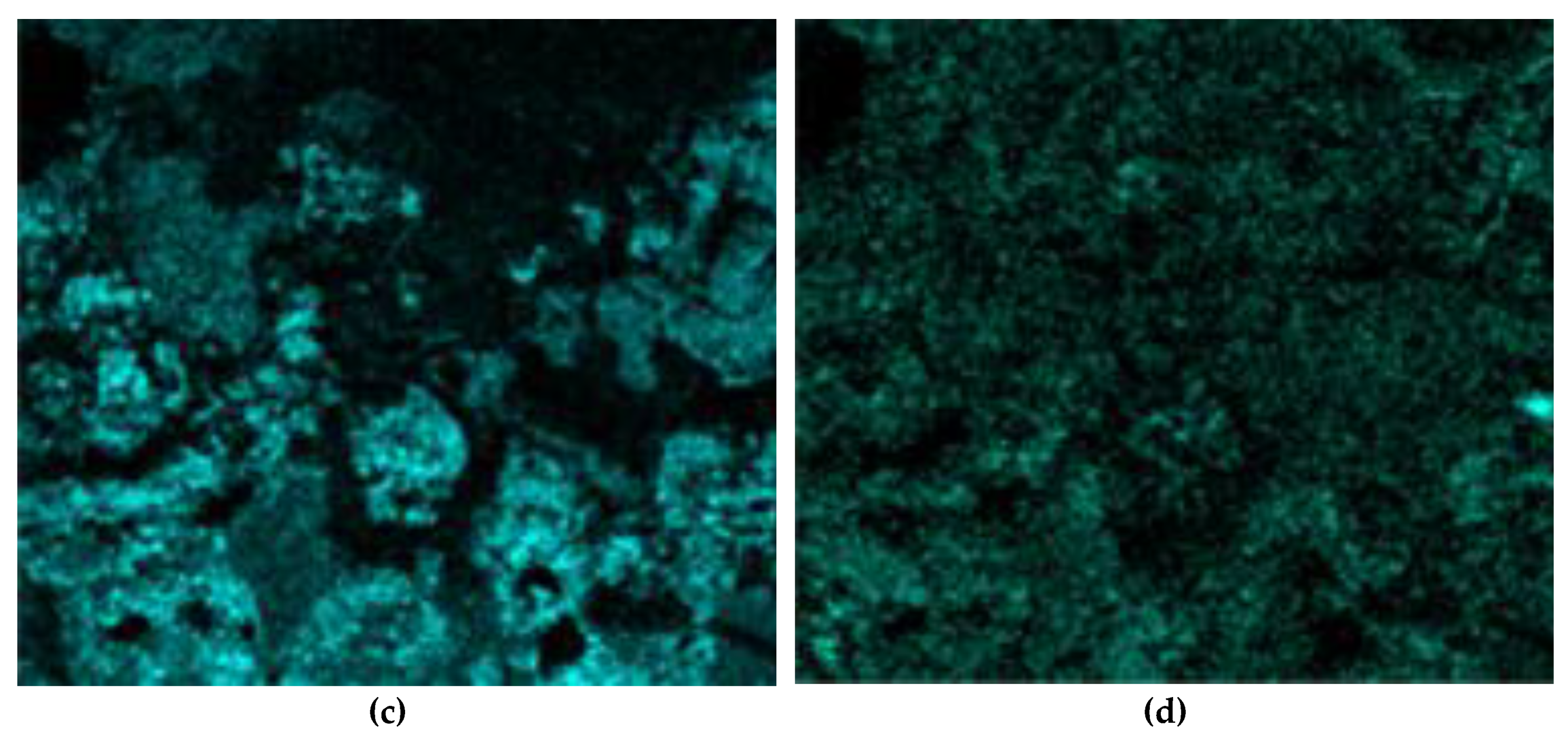
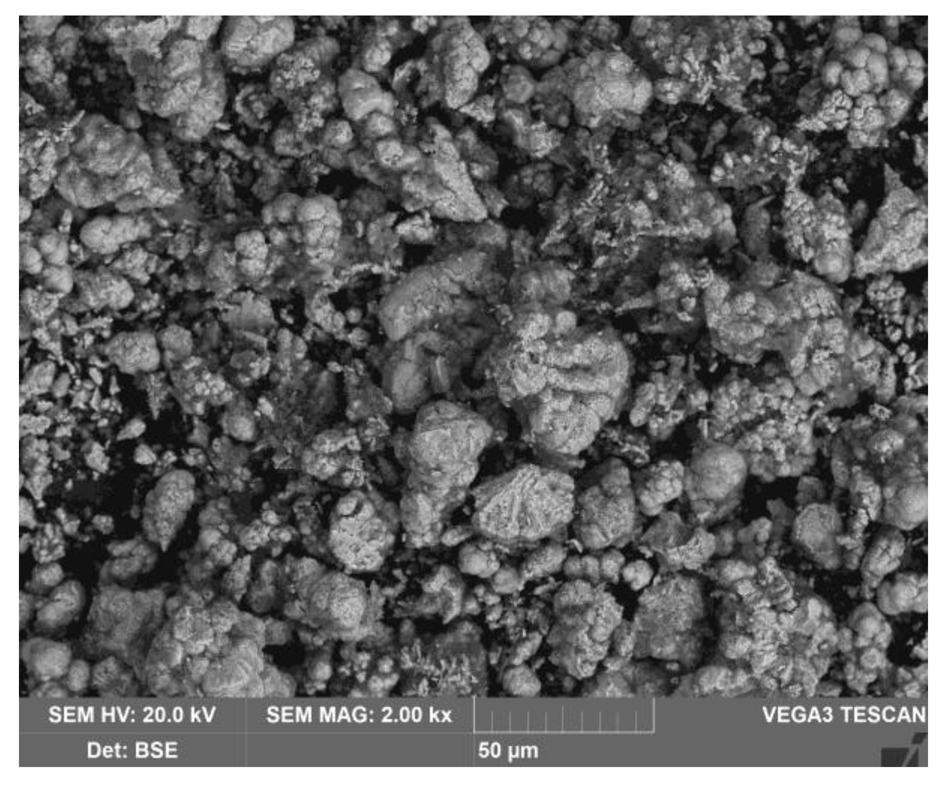
  • Examining the electrolysis product using SEM-EDS revealed the formation of dense, iron-containing phase on the surface of the particles, which prevented outward diffusion of the reaction products.
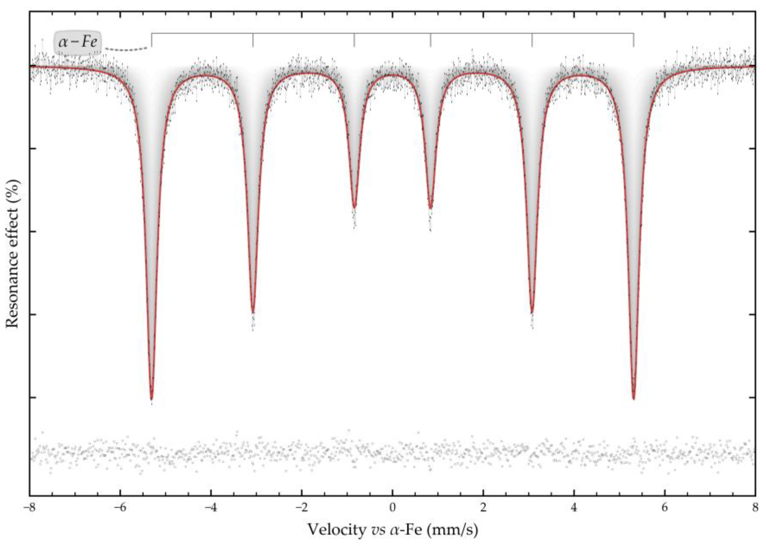
  • Mössbauer studies of the high-pressure leaching product showed that the main iron-containing phases of BR are maghemite, which is formed during the hydrolysis of sodium ferrite.

Author Contributions

Conceptualization, A.S. and I.L.; Methodology, A.S.; Software, D.V.; Validation, D.V. and D.P.; Formal analysis, I.L.; Investigation, A.S. and D.V.; Resources, A.S.; Data curation, A.S.; Writing—original draft preparation, A.S. and D.V.; Writing—review and editing, D.V. and D.P.; Visualization, A.S.; Supervision, D.P.; Project administration, I.L.; Funding acquisition, I.L. All authors have read and agreed to the published version of the manuscript.

Funding

Research was funded by the Project of the State Assignment, FEUZ-2024-0010. The methods for determining the chemical composition of raw bauxite and solid residue after pulp filtration by XRF (see Section 2.2. “Analytical methods”) were funded by the Project of the State Assignment (Vernadsky Institute of Geochemistry and Analytical Chemistry of Russian Academy of Sciences, No. FMMZ-2024-0045). Mössbauer analysis was performed in accordance with the state assignment of Lomonosov Moscow State University “Development of methodology of chemistry of molecular ensembles of natural humic systems aimed at rational design of nature-like structures and materials, ecological chemistry and ecoadaptive technologies for protection of human and environmental health” (Project Reg. No. 122040600057-3).

Data Availability Statement

All data are presented in this article.

Acknowledgments

The authors express their gratitude to Evgeny Kolesnikov from NUST MISiS for assistance with the SEM and XRD analyses of the solid samples.

Conflicts of Interest

The authors declare no conflict of interest.

Abbreviations

The following abbreviations are used in this manuscript:
BR Bauxite residue
XRF X-ray fluorescence
XRD X-Ray diffraction
SEM-EDS Scanning electron microscopy with the energy dispersive spectroscopy analysis

References

  1. Li, Q.; Lv, G.; Wang, S.; Li, X.; He, X.; Zhang, T. Summary of Research Progress on the Separation and Extraction of Iron from Bayer Red Mud. J. Sustain. Metall. 2025, 11, 186–213. [Google Scholar] [CrossRef]
  2. Smith, P. The Processing of High Silica Bauxites — Review of Existing and Potential Processes. Hydrometallurgy 2009, 98, 162–176. [Google Scholar] [CrossRef]
  3. Pan, X.; Yu, H.; Tu, G.; Bi, S. Effects of Precipitation Activity of Desilication Products (DSPs) on Stability of Sodium Aluminate Solution. Hydrometallurgy 2016, 165, 261–269. [Google Scholar] [CrossRef]
  4. Cheng, L.; Wang, Y.; Wang, B.; Qi, T.; Liu, G.; Zhou, Q.; Peng, Z.; Li, X. Phase Transformation of Desilication Products in Red Mud Dealkalization Process. J. Sustain. Metall. 2022, 8, 541–550. [Google Scholar] [CrossRef]
  5. Liu, G.; Liu, Y.; Zhang, T. Approaches to Improve Alumina Extraction Based on the Phase Transformation Mechanism of Recovering Alkali and Extracting Alumina by the Calcification-Carbonization Method. Hydrometallurgy 2019, 189, 105123. [Google Scholar] [CrossRef]
  6. Wang, Y.; Zhang, T.; Lyu, G.; Ma, L.; Zhang, W. Multi-Material Circulation Optimization of the Calcification-Carbonation Process Based on Material Balance and Phase Transformation for Cleaner Production of Alumina. Journal of Cleaner Production 2021, 290, 125828. [Google Scholar] [CrossRef]
  7. Medvedev, V.V.; Akhmedov, S.N.; Lipin, V.A. Hydrogarnet Process as a Modern Approach to Hydrometallurgical Alkaline Processing of Low-Grade Bauxites. Review. tsm 2023, 51–57. [Google Scholar] [CrossRef]
  8. Hond, R.D.; Hiralal, I.; Rijkeboer, A. Alumina Yield in the Bayer Process Past, Present and Prospects. In Essential Readings in Light Metals; Donaldson, D., Raahauge, B.E., Eds.; John Wiley & Sons, Inc.: Hoboken, NJ, USA, pp. 528–533, 2013; ISBN 978-1-118-64786-8. [Google Scholar]
  9. Cardenia, C.; Balomenos, E.; Wai Yin Tam, P.; Panias, D. A Combined Soda Sintering and Microwave Reductive Roasting Process of Bauxite Residue for Iron Recovery. Minerals 2021, 11, 222. [Google Scholar] [CrossRef]
  10. Chen, J.; Li, X.; Cai, W.; Shi, Y.; Hui, X.; Cai, Z.; Jin, W.; Fan, J. High-Efficiency Extraction of Aluminum from Low-Grade Kaolin via a Novel Low-Temperature Activation Method for the Preparation of Poly-Aluminum-Ferric-Sulfate Coagulant. Journal of Cleaner Production 2020, 257, 120399. [Google Scholar] [CrossRef]
  11. Mayes, W.M.; Burke, I.T.; Gomes, H.I.; Anton, Á.D.; Molnár, M.; Feigl, V.; Ujaczki, É. Advances in Understanding Environmental Risks of Red Mud After the Ajka Spill, Hungary. Journal of Sustainable Metallurgy 2016, 2, 332–343. [Google Scholar] [CrossRef]
  12. Abdul, F.; Isworo, G.; Mahaputra, R.; Pintowantoro, S. Possible Strategies for Red Mud Neutralization and Dealkalization from the Alumina Production Industry: A Review for Indonesia. Int. J. Environ. Sci. Technol. 2025, 22, 5159–5178. [Google Scholar] [CrossRef]
  13. Anawati, J.; Azimi, G. Integrated Carbothermic Smelting – Acid Baking – Water Leaching Process for Extraction of Scandium, Aluminum, and Iron from Bauxite Residue. Journal of Cleaner Production 2022, 330, 129905. [Google Scholar] [CrossRef]
  14. Angelopoulos, P.; Oustadakis, P.; Kountouris, N.; Samouhos, M.; Anastassakis, G.; Taxiarchou, M. Iron Recovery from Turkish and Romanian Bauxite Residues Through Magnetic Separation: Effect of Hydrothermal Processing and Separation Conditions. Separations 2025, 12, 252. [Google Scholar] [CrossRef]
  15. Rai, S.; Nimje, M. t.; Chaddha, M. j.; Modak, S.; Rao, K. r.; Agnihotri, A. Recovery of Iron from Bauxite Residue Using Advanced Separation Techniques. Minerals Engineering 2019, 134, 222–231. [Google Scholar] [CrossRef]
  16. Borra, C.R.; Blanpain, B.; Pontikes, Y.; Binnemans, K.; Van Gerven, T. Recovery of Rare Earths and Other Valuable Metals From Bauxite Residue (Red Mud): A Review. J. Sustain. Metall. 2016, 2, 365–386. [Google Scholar] [CrossRef]
  17. Agrawal, S.; Dhawan, N. Investigation of Carbothermic Microwave Reduction Followed by Acid Leaching for Recovery of Iron and Aluminum Values from Indian Red Mud. Minerals Engineering 2020, 159, 106653. [Google Scholar] [CrossRef]
  18. Stopic, S.; Kostić, D.; Schneider, R.; Sievers, M.; Wegmann, F.; Emil Kaya, E.; Perušić, M.; Friedrich, B. Recovery of Titanium from Red Mud Using Carbothermic Reduction and High Pressure Leaching of the Slag in an Autoclave. Minerals 2024, 14, 1151. [Google Scholar] [CrossRef]
  19. Gao, F.; Zhang, J.; Deng, X.; Wang, K.; He, C.; Li, X.; Wei, Y. Comprehensive Recovery of Iron and Aluminum from Ordinary Bayer Red Mud by Reductive Sintering–Magnetic Separation–Digesting Process. JOM 2019, 71, 2936–2943. [Google Scholar] [CrossRef]
  20. Wang, Y.; Li, X.; Zhou, Q.; Wang, B.; Qi, T.; Liu, G.; Peng, Z.; Pi, J.; Zhao, Z.; Wang, M. Reduction of Red Mud Discharge by Reductive Bayer Digestion: A Comparative Study and Industrial Validation. JOM 2020, 72, 270–277. [Google Scholar] [CrossRef]
  21. He, X.; Lv, G.; Liu, B.; Li, Q.; Zhang, X.; Yun, Z.; Zhang, T. Straw-Induced Hematite-to-Magnetite Conversion in Alkaline Media: Experimental Study and Potential in Bayer Process. Minerals Engineering 2025, 234, 109723. [Google Scholar] [CrossRef]
  22. Maihatchi, A.; Pons, M.-N.; Ricoux, Q.; Goettmann, F.; Lapicque, F. Electrolytic Iron Production from Alkaline Suspensions of Solid Oxides: Compared Cases of Hematite, Iron Ore and Iron-Rich Bayer Process Residues. J. Electrochem. Sci. Eng. 2020, 10, 95–102. [Google Scholar] [CrossRef]
  23. Koutsoupa, S.; Koutalidi, S.; Bourbos, E.; Balomenos, E.; Panias, D. Electrolytic Iron Production from Alkaline Bauxite Residue Slurries at Low Temperatures : Carbon-Free Electrochemical Process for the Production of Metallic Iron. Johnson Matthey Technology Review 2021, 65, 366–374. [Google Scholar] [CrossRef]
  24. Shoppert, A.; Valeev, D.; Loginova, I. Novel Method of Bauxite Treatment Using Electroreductive Bayer Process. Metals 2023, 13, 1502. [Google Scholar] [CrossRef]
  25. Matsnev, M.E.; Rusakov, V.S. SpectrRelax: An Application for Mцssbauer Spectra Modeling and Fitting. AIP Conference Proceedings 2012, 1489, 178–185. [Google Scholar] [CrossRef]
  26. Zhang, J.; Li, Y.; Gao, P.; Yuan, S.; Zhou, W. Advances in Reagent Systems and Mechanisms for Desilication from Bauxite via Flotation. Reviews in Chemical Engineering 2025, 41, 645–665. [Google Scholar] [CrossRef]
  27. Jones, D.H.; Srivastava, K.K.P. Many-State Relaxation Model for the Mössbauer Spectra of Superparamagnets. Phys. Rev. B 1986, 34, 7542–7548. [Google Scholar] [CrossRef]
  28. Dzeranov, A.; Bondarenko, L.; Pankratov, D.; Dzhardimalieva, G.; Jorobekova, S.; Saman, D.; Kydralieva, K. Impact of Silica-Modification and Oxidation on the Crystal Structure of Magnetite Nanoparticles. Magnetochemistry 2023, 9, 18. [Google Scholar] [CrossRef]
  29. Moiseeva, E.O.; German, S.V.; Komlev, A.S.; Rusakov, V.S.; Zuev, V.V.; Pavlova, O.S.; Perepukhov, A.M.; Dmitrienko, A.O.; Maslakov, K.I.; Griaznova, O.Y.; et al. Citrate Stabilized Maghemite Hydrosol with Controllable MRI Contrast: Key Role of Nanoparticle Size. Journal of Magnetism and Magnetic Materials 2024, 608, 172447. [Google Scholar] [CrossRef]
  30. Lee, S.W.; Kim, C.S. Mössbauer Studies on the Superparamagnetic Behavior of CoFe2O4 with a Few Nanometers. Journal of Magnetism and Magnetic Materials 2006, 303, e315–e317. [Google Scholar] [CrossRef]
  31. Winkler, W. Mössbauer Studies of Small Magnetite Particles of a Magnetic Fluid. Phys. Stat. Sol. (a) 1984, 84, 193–198. [Google Scholar] [CrossRef]
  32. Shoppert, A.; Valeev, D.; Loginova, I.; Pankratov, D. Low-Temperature Treatment of Boehmitic Bauxite Using the Bayer Reductive Method with the Formation of High-Iron Magnetite Concentrate. Materials 2023, 16, 4678. [Google Scholar] [CrossRef]
  33. Fysh, S.A.; Clark, P.E. Aluminous Hematite: A M�ssbauer Study. Phys Chem Minerals 1982, 8, 257–267. [Google Scholar] [CrossRef]
  34. De Grave, E.; Bowen, L.H.; Weed, S.B. Mössbauer Study of Aluminum-Substituted Hematites. Journal of Magnetism and Magnetic Materials 1982, 27, 98–108. [Google Scholar] [CrossRef]
  35. Ji-Sen, J.; Xie-Long, Y.; Long-Wu, C.; Nai-Fu, Z. Mössbauer Studies of the Morin Transition Interval of Uniform Hematite Particles. Hyperfine Interact 1988, 41, 483–486. [Google Scholar] [CrossRef]
  36. Onodera, H.; Fujita, A.; Yamamoto, H.; Sagawa, M.; Hirosawa, S. Mössbauer Study of the Intermetallic Compound Nd2Fe14B. I. Interpretation of Complex Spectrum. Journal of Magnetism and Magnetic Materials 1987, 68, 6–14. [Google Scholar] [CrossRef]
  37. Shokanov, A.; Vereshchak, M.; Manakova, I.; Migunova, A. Mössbauer and X-Ray Diffraction Spectroscopy of High-Iron Bauxites from Kazakhstan. Materials 2023, 16, 6706. [Google Scholar] [CrossRef]
  38. Lopes, D.V.; Ivanova, Yu.A.; Kovalevsky, A.V.; Sarabando, A.R.; Frade, J.R.; Quina, M.J. Electrochemical Reduction of Hematite-Based Ceramics in Alkaline Medium: Challenges in Electrode Design. Electrochimica Acta 2019, 327, 135060. [Google Scholar] [CrossRef]
  39. Monteiro, J.F.; Ivanova, Yu.A.; Kovalevsky, A.V.; Ivanou, D.K.; Frade, J.R. Reduction of Magnetite to Metallic Iron in Strong Alkaline Medium. Electrochimica Acta 2016, 193, 284–292. [Google Scholar] [CrossRef]
  40. Kicheeva, A.G.; Sushko, E.S.; Bondarenko, L.S.; Kydralieva, K.A.; Pankratov, D.A.; Tropskaya, N.S.; Dzeranov, A.A.; Dzhardimalieva, G.I.; Zarrelli, M.; Kudryasheva, N.S. Functionalized Magnetite Nanoparticles: Characterization, Bioeffects, and Role of Reactive Oxygen Species in Unicellular and Enzymatic Systems. IJMS 2023, 24, 1133. [Google Scholar] [CrossRef]
  41. Gorski, C.A.; Scherer, M.M. Determination of Nanoparticulate Magnetite Stoichiometry by Mossbauer Spectroscopy, Acidic Dissolution, and Powder X-Ray Diffraction: A Critical Review. American Mineralogist 2010, 95, 1017–1026. [Google Scholar] [CrossRef]
  42. Orozco-Henao, J.M.; Muraca, D.; Sánchez, F.H.; Mendoza Zélis, P. Determination of the Effective Anisotropy of Magnetite/Maghemite Nanoparticles from Mössbauer Effect Spectra. J. Phys. D: Appl. Phys. 2022, 55, 335302. [Google Scholar] [CrossRef]
  43. Önal, M.A.R.; Riaño, S.; Binnemans, K. Alkali Baking and Solvometallurgical Leaching of NdFeB Magnets. Hydrometallurgy 2020, 191, 105213. [Google Scholar] [CrossRef]
  44. Pankratov, D.A.; Anuchina, M.M. Nature-Inspired Synthesis of Magnetic Non-Stoichiometric Fe3O4 Nanoparticles by Oxidative in Situ Method in a Humic Medium. Materials Chemistry and Physics 2019, 231, 216–224. [Google Scholar] [CrossRef]
  45. Filimonov, D.; Rozova, M.; Maksimov, S.; Pankratov, D. Synthesis and Redox Properties of Iron and Iron Oxide Nanoparticles Obtained by Exsolution from Perovskite Ferrites Promoted by Auxiliary Reactions. Inorganics 2024, 12, 223. [Google Scholar] [CrossRef]
  46. Yoshida, Y.; Nasu, S.; Fujita, F.E.; Maeda, Y.; Yoshida, H. 57Fe Mössbauer Study on Point Defects in Pure α-Fe. Journal of Magnetism and Magnetic Materials 1983, 31–34, 753–754. [Google Scholar] [CrossRef]
  47. Grudinsky, P.; Zinoveev, D.; Pankratov, D.; Semenov, A.; Panova, M.; Kondratiev, A.; Zakunov, A.; Dyubanov, V.; Petelin, A. Influence of Sodium Sulfate Addition on Iron Grain Growth during Carbothermic Roasting of Red Mud Samples with Different Basicity. Metals 2020, 10, 1571. [Google Scholar] [CrossRef]
  48. Nemoshkalenko, V.V.; Rasumov, O.N.; Gorskii, V.V. Investigation of the Mössbauer Effect in Some Fe–Al Alloys. Physica Status Solidi (b) 1968, 29, 45–48. [Google Scholar] [CrossRef]
  49. Vincze, I.; Campbell, I.A. Mossbauer Measurements in Iron Based Alloys with Transition Metals. Journal of Physics F: Metal Physics 1973, 3, 647–663. [Google Scholar] [CrossRef]
  50. Chernavskii, P.A.; Kazantsev, R.V.; Pankina, G.V.; Pankratov, D.A.; Maksimov, S.V.; Eliseev, O.L. Unusual Effect of Support Carbonization on the Structure and Performance of Fe/Mgal2 o4 Fischer–Tropsch Catalyst. Energy Tech 2021, 9, 2000877. [Google Scholar] [CrossRef]
  51. Liu, X.-W.; Zhao, S.; Meng, Y.; Peng, Q.; Dearden, A.K.; Huo, C.-F.; Yang, Y.; Li, Y.-W.; Wen, X.-D. Mössbauer Spectroscopy of Iron Carbides: From Prediction to Experimental Confirmation. Sci Rep 2016, 6, 26184. [Google Scholar] [CrossRef]
  52. Mostafa, M.A.; Balogh, J.; Kuzmann, E. Mössbauer Study of (Fe1−xCox)77B13Si10 Amorphous Alloys. phys. stat. sol. (a) 1986, 96, 445–449. [Google Scholar] [CrossRef]
  53. Zhou, G.; Wang, Y.; Qi, T.; Zhou, Q.; Liu, G.; Peng, Z.; Li, X. Cleaning Disposal of High-Iron Bauxite Residue Using Hydrothermal Hydrogen Reduction. Bull Environ Contam Toxicol 2022, 109, 163–168. [Google Scholar] [CrossRef] [PubMed]
Figure 1. Schematic view of experimental setups used to study the process of electroreduction of bauxite iron minerals in alkaline media (mesh current supply).
Preprints 186862 g001
Figure 2. X-ray diffraction (XRD) pattern of the boehmitic bauxite.
Preprints 186862 g002
Figure 3. Mössbauer spectra of the raw bauxite (a, b) and bauxite residue (c, d) samples at 296 (a, c) and 78 K (b, d).
Preprints 186862 g003
Figure 4. Pourbaix diagram for the Fe system at 70 °C: (a) for Fe concentration 0.2×10⁻³ M; (b) for concentration 3.1×10⁻³ M.
Preprints 186862 g004
Figure 5. Results of cyclic voltammetry (CV) at a temperature of 120 °C after 300 s of electrolytic reduction of iron minerals in a suspension of large bauxite particles in an alkaline solution with a Na2O concentration of 400 g/L.
Preprints 186862 g005
Figure 6. Results of cyclic voltammetry (CV) at a temperature of 120 °C after 1800 s of electrolytic reduction of iron minerals in a suspension of large bauxite particles in an alkaline solution with a Na2O concentration of 400 g/L.
Preprints 186862 g006
Figure 7. The dependence of the cathode potential on electrolysis time at 120 °C and a constant current of 2 A, using a mesh cathode and suspension of a large bauxite particles in an alkaline solution.
Preprints 186862 g007
Figure 8. Results showing the effect of electrolysis duration on current efficiency, the degree of magnetization of iron minerals and current yield (based on Fe only).
Preprints 186862 g008
Figure 9. Optical microscope images of: (a) surface of the bauxite particles after reduction; (b) inner part of the particles.
Preprints 186862 g009
Figure 10. Results of SEM-EDS analysis of the surface of coarse BR particles after electrolysis: (a) SEM image of the particle cross-section; (b) map of Fe distribution; (c) map of Al distribution; (d) map of Na distribution.
Preprints 186862 g010aPreprints 186862 g010b
Figure 11. Mechanism of dense layer formation on the surface of bauxite particles during electrolysis.
Preprints 186862 g011
Figure 12. XRD patterns of the electroreduction product and the solid residue after high-pressure leaching.
Preprints 186862 g012
Figure 13. Magnetization curves for the electroreduction product and the solid residue after high-pressure leaching.
Preprints 186862 g013
Figure 14. SEM image of the iron deposited on a mesh cathode after 2 h of electrolysis.
Preprints 186862 g014
Figure 15. The Mössbauer spectrum of the cathodic iron at 296 K, where the height of the line of the experimental point is equal to the error in its determination, and the subspectrum that simulates the experimental data, and the differential spectrum between them.
Preprints 186862 g015
Table 1. Semi quantitative composition of the raw boehmitic bauxite.
Phase wt.%
Boehmite 62.3
Hematite 25.7
Alumogoethite 3.6
Chamosite 3.4
Rutile 2.6
Diaspore 2.4
Table 2. Result of XRF analysis of the raw boehmitic bauxite, wt. %.
Al2O3 Fe2O3 SiO2 TiO2 Na2O CaO MgO SO3 P2O5 Other µSi1 LOI2
50.3 26.8 6.5 2.7 0.1 0.9 0.5 0.01 0.1 1.1 7.7 11.0
1 µSi – wt. ratio of Al2O3 to SiO2.2 Lost on ignition at 1100 °C.
Table 3. Hyperfine parameters of the Mössbauer spectra at 78 and 296 K for the samples.
Temperature, K 296(3) 77.7(3)
Sample Phase *δ ε {Δ} Γexp Heff S α δ ε (Δ) Γexp Heff S
mm/s kOe % - mm/s kOe %
Boehmitic bauxite 1 α-Fe(Al)2O3 0.37(1) -0.11(1) 0.28(1) 509.9(3) 27.9(2.5) 0.48(1) -0.10(1) 0.30(1) 528.1(2) 44.4(8)
2 α-Fe(Al)2O3 0.38(1) -0.10(1) 0.58(2) 496.2(1.3) 23.8(2.6)
3 α-Fe(Al)OOH 0.33(2) -0.12(2) 0.54(7) 390.8(2.1) 14.2(6) 3.2(3) 0.48(1) -0.11(1) 0.74(3) 499.9(6) 26.7(1.0)
4 Fe2+Oh 1.13(1) {2.65(1)} 0.34(1) 20.9(3) 1.25(1) {2.80(1)} 0.31(1) 21.0(3)
5 Fe3+Oh 0.39(1) {0.67(1)} 0.48(1) 13.2(5) 0.51(1) {0.85(1)} 0.53(2) 7.9(3)
Bauxite residue 1 α-Fe2O3 0.37(1) -0.11(1) 0.29(1) 510.8(1) 24.6(6) 0.49(1) -0.10(1) 0.30(1) 531.0(1) 30.0(8)
2 γ-Fe(Al)2O3 0.32(1) -0.05(1) 0.54(1) 486.4(3) 29.8(9) 0.45(1) -0.03(1) 0.66(1) 507.5(3) 48(1)
3 γ-Fe(Al,M)2O3 0.59(1) -0.03(1) 0.66(2) 473.3(9) 40(1) 6.4(3) 0.82(1) -0.15(1) 0.97(5) 472(1) 18(1)
4 α-Fe(Al,M)OOH 0.28(6) -0.12(5) 0.66(2) 387(4) 3.4(5) 0.74(4) 0.01(4) 0.7(2) 405(3) 2.9(7)
5 Fe3+Td 0.22(3) {0.78(6)} 0.64(1) 2.0(2) 0.44(3) {0.72(5)} 0.36(7) 1.1(1)
Table 4. The results of determining the equilibrium concentration of iron upon contact between alkaline solutions of varying concentrations and iron monomineral, ×103 M.
Hematite (α-Fe2O3) Temperature, °C
Na2O concentration, g/L 60 80 100 120
300 0.3 0.5 0.9 -*
400 0.3 0.7 1.6 1.9
550 0.5 1.0 2.1 2.6
Goethite (FeOOH) Temperature, °C
Na2O concentration, g/L 60 80 100 120
300 0.2 0.4 0.7 -
400 0.4 0.5 1.4 1.6
550 0.5 0.6 1.8 2.0
Chamosite ((Fe2+,Mg,Al,Fe3+)6(Si,Al)4O10(OH,O)8 Temperature, °C
Na2O concentration, g/L 60 80 100 120
300 0.3 0.6 0.8 -
400 0.5 0.8 1.5 1.8
550 0.6 1.1 2.1 3.1
* This temperature is not studied for concentration 300 g/L.
Table 5. Result of XRF analysis of the of the solid residue after 2 h of electrolysis at a constant current of 2 A, a temperature of 120 °C and a S:L ratio of 1:3 in a 400 g/L Na₂O alkaline solution and bauxite residue after high-pressure leaching, wt. %.
Sample Al2O3 Fe2O3 SiO2 TiO2 Na2O CaO MgO SO3 P2O5 Other LOI
Electroreduction product 28.3 37.8 3.9 3.9 12.2 1.3 0.7 0.01 0.1 1.5 10.5
BR 10.2 61.9 6.5 6.5 3.2 1.8 1.3 0.01 0.01 1.8 6.7
Disclaimer/Publisher’s Note: The statements, opinions and data contained in all publications are solely those of the individual author(s) and contributor(s) and not of MDPI and/or the editor(s). MDPI and/or the editor(s) disclaim responsibility for any injury to people or property resulting from any ideas, methods, instructions or products referred to in the content.
Copyright: This open access article is published under a Creative Commons CC BY 4.0 license, which permit the free download, distribution, and reuse, provided that the author and preprint are cited in any reuse.
Prerpints.org logo

Preprints.org is a free preprint server supported by MDPI in Basel, Switzerland.

Subscribe

Disclaimer

Terms of Use

Privacy Policy

Privacy Settings

© 2025 MDPI (Basel, Switzerland) unless otherwise stated