
Submitted:
24 November 2025
Posted:
24 November 2025
You are already at the latest version
Abstract
Advanced two-dimensional (2D) beam steering is critical for unlocking the full potential of terahertz (THz) systems in future 6G communications and high-resolution imaging. However, realizing wide-angle, high-speed, and high-precision 2D beam control in a compact and simple THz front end remains challenging. This paper experimentally demonstrates a photonics-assisted 2×2 THz antenna array that enables flexible 2D beam steering, 2D beam hopping, and fast 2D beam scanning around the 300-GHz band. The proposed front end is an integrated THz photomixer composed of a 2×2 microstrip patch antenna (MPA) array directly fed by InGaAs/InP uni-traveling-carrier photodiodes (UTC-PDs) on a silicon carbide (SiC) substrate. The relative phases of the four radiating elements are precisely controlled by an optical phased array (OPA), providing a fully decoupled and low-latency phase control mechanism. Experimentally, we realize 2D beam steering and 2D beam hopping among three representative beam directions at an elevation angle of 25° with azimuth angles of 60°, 180°, and 300°. Furthermore, continuous 2D beam scanning is demonstrated at a fixed elevation of 25°, achieving a full 360° azimuth sweep within 0.43 s while maintaining high beam quality. These results confirm that the proposed 2×2 photomixer-based array offers a practical and robust solution for agile 2D THz beam manipulation, and holds strong promise for future 6G wireless links and THz image sensing applications.
Keywords:
terahertz
; 2D beam steering
; antenna array
; phased array
; 6G communications
1. Introduction
Terahertz (THz) waves in the 0.1–10 THz band have emerged as key enablers for beyond-5G/6G wireless systems thanks to their extremely wide available bandwidth and the possibility of realizing highly directive yet compact antennas [1,2]. Extensive reviews have surveyed the progress and challenges of THz wireless communications, channel characteristics, and enabling device technologies [3,4,5]. In parallel, a variety of high-speed THz wireless links, including optoelectronic systems, have been experimentally demonstrated with data rates from several gigabits per second up to beyond 100 Gbit/s [6,7,8]. Around 300 GHz in particular, the wavelength is on the order of 1 mm, which enables electrically small transmitters while still supporting multi-gigabit to terabit-per-second links over short distances. At the same time, THz technology has matured to the point where it now underpins not only high-throughput communications but also spectroscopic imaging, non-destructive evaluation, and high-resolution radars [9]. Propagation in this band, however, is strongly impacted by atmospheric gaseous absorption and requires high-gain links with dynamically steerable beams [10,11,12].
Recent tutorials and reviews classify THz beam-steering techniques into several main categories, including phased arrays, quasi-optical/lens-based architectures, and frequency-dispersive leaky-wave and metasurface approaches [11,12,13,14]. Among these, phased-array antennas (PAAs) offer the most flexible control of beam direction and shape. In principle, arbitrary two-dimensional (2D) beam steering can be achieved by independently programming the phase of each element, and array theory developed at microwave frequencies is directly applicable once suitable THz hardware is available [15]. At THz frequencies, both fully electronic and hybrid electronic–photonic implementations have been demonstrated, including an integrated transmitter that combine on-chip antennas, phase-control networks, and frequency-generation circuitry [13]. In the photonic domain, microwave photonics provides ultra-wide instantaneous bandwidths, low RF loss, and the ability to shift beamforming/phase control to the optical layer [16]. For example, Che et al. demonstrated optoelectronic-phased-array-driven THz power combination and beam steering at 300 GHz [17] and 450 GHz [18]; Li et al. reported photonic-assisted, frequency-independent beam steering suitable for wideband THz links [19], and real-time optoelectronic THz beam tracking via phase optimization [20]. These works collectively highlight the promise of photonic-assisted PAAs for agile THz communications and sensing.
Leaky-wave antennas (LWAs) and related frequency-scanning structures represent another powerful class of THz beam-steering devices, where a traveling wave with controlled phase velocity leaks radiation continuously along the structure and the main beam angle follows the dispersion relation [11,12]. Representative demonstrations include a low-profile THz radar with broadband leaky-wave steering [21], a planar 2D frequency-scanning array with improved efficiency [22], and wide-angle beam coverage around 300 GHz has also been demonstrated using trajectory-deflection methods, including dielectric-free Luneburg lenses and leaky-mode structures [23,24]. However, because the steering mechanism is inherently tied to frequency, wideband communication signals inevitably suffer beam-squint unless compensated [25], and very wide frequency sweeps may be incompatible with regulatory or system constraints.
Quasi-optical beamforming based on dielectric or gradient-index lenses provides an alternative route to high-gain steering with low loss and broad bandwidth, and naturally offers frequency-independent focusing with a fixed feed [23]. 2D steering with lenses, however, typically requires two-axis translation/rotation or cascaded elements, increasing mechanical complexity, footprint, and cost, while lacking the fine, high-speed electronic control available in PAAs.
These challenges motivate a compact, optoelectronic 2D phased-array transmitter that avoid frequency scanning and bulky mechanics, and leverage low-loss optical distribution with phase programmability.
In this work, we propose and experimentally demonstrate such an optoelectronic 2D beam-steering approach based on an integrated 2×2 THz antenna array with UTC-PDs operating in the 300-GHz band. The THz transmitter comprises a microstrip patch antenna (MPA) array directly fed by InGaAs/InP uni-traveling-carrier photodiodes (UTC-PDs) integrated on a silicon carbide (SiC) substrate, a mature platform for THz generation [26,27,28,29]. An optical phased array (OPA) controls the excitation phase of each MPA element using thermo-optic phase shifters on a low-loss optical chip to set each phase independently and continuously [30,31]. Using this array, we experimentally demonstrate flexible 2D beam manipulation towards target directions defined by the polar angle and azimuthal angle . Specifically, we achieved 2D beam hopping among three representative directions at a fixed polar angle of (with azimuthal angles ) and realized continuous 2D beam scanning along a constant-polar circle. By dynamically updating the OPA phases, a full azimuth sweep at was completed within 0.43 s while maintaining high beam quality. These results confirm that a compact UTC-PD-based array with OPA-driven phase control provides a practical solution for flexible 2D THz beam steering, hopping, and scanning around 300 GHz, and offers a promising pathway toward 6G-class wireless links, imaging, and sensing.
2. Principle and System Design
2.1. Concept
We consider a uniform 2×2 MPA array located in the x–y plane at , as illustrated in Figure 1. The four radiating MPAs are indexed by , where . They are arranged in a uniform rectangular grid with inter-MPA spacings and along the x and y directions, respectively. The position vector of the -th MPA is
For a far-field observation direction specified by polar (from the z-axis) and azimuth (from the x-axis in the x–y plane), the corresponding wave vector is
Let the complex excitation of the -th MPA be
where denotes the uniform excitation amplitude across all MPA elements, and is the controllable phase provided by the OPA through the corresponding UTC-PD. The array factor (AF) of the 2×2 array is then written as
To realize uniform 2D beam steering, we impose linear phase progressions along x and y,
where and are the phase steps between adjacent MPAs along the x and y axes, and is a common phase term. Substituting this into Equation (4) yields
The main beam is steered towards a target direction when the progressive phases cancel the phase terms associated with that direction, i.e.,
Under this condition, the phase of every term in the summation of Equation (6) become in-phase at , so that is maximized and the main lobe points to the desired 2D angle.
2.2. THz Antenna Array Integrated with UTC-PDs
Figure 2 presents a monolithically integrated THz emitter operating in the 300 GHz band, composed of a 2×2 MPA array directly fed by four InGaAs/InP UTC-PDs on a SiC substrate. As shown in Figure 2(a), each MPA employs an inset-fed rectangular geometry optimized for impedance matching of microstrip line (MSL) at 300 GHz. The individual patch dimensions are 146 in length and 213 in width, while the horizontal and vertical spacings between array elements are 500 and 400 , respectively. These parameters are optimized to achieve high radiation efficiency and low side-lobe levels within the 300 GHz band. Each MPA is directly connected to a UTC-PD via a 50 feeding MSL, enabling efficient optical-to-THz signal conversion and radiation. Figure 2(b) presents the cross-sectional configuration of the integrated UTC-PDs. The SiC substrate has a thickness of 32 , and a 40 -diameter aperture is opened in the ground plane to enable backside optical coupling into the UTC-PD absorption region. The spacing between adjacent UTC-PDs is 500 , optimized for micro-lens array (MLA) coupling to achieve precise optical alignment and focusing. In addition, integrated low-pass filters (LPFs) based on MSL are included to provide reverse DC bias to the UTC-PDs while effectively suppressing RF leakage toward the bias circuitry. Owing to the constraint of backside optical coupling with a MLA, the four UTC-PDs are arranged in a linear array along one side of the 2×2 MPA aperture rather than in a symmetric 2×2 configuration. As a result, each UTC-PD is connected to its corresponding MPA through a microstrip feed line of different electrical length.
In a purely electronic phased array, such asymmetric feeds would introduce fixed phase errors that must be equalized at the RF layout level. In the proposed optoelectronic architecture, these deterministic phase offsets are instead treated as part of the steering law and are compensated in the optical domain by appropriate OPA phase settings, thereby relaxing the requirement for strictly identical RF feed lines on the THz chip.
The operating principle of the UTC-PD is based on optical heterodyne mixing. When two coherent optical tones with a frequency difference are simultaneously incident on the photodiode, the resulting optical intensity includes a beat component at , generating an AC photocurrent at the corresponding THz frequency. Unlike conventional p-i-n photodiodes, the UTC-PD employs a carrier transport mechanism dominated solely by electrons. Photogenerated holes are quickly relaxed in the thin absorption layer, while only electrons travel through the high-field collector region toward the cathode. This uni-traveling-carrier transport greatly reduces transit time and parasitic capacitance, achieving bandwidths exceeding 300 GHz. In this work, the epitaxy layers of the InGaAs/InP UTC-PD are grown on a native InP wafer, which is then bonded to a SiC substrate through a flip wafer bonding process [32,33]. The adoption of SiC is primarily motivated by its high thermal conductivity (350 W/m·K) [34], which greatly enhances heat dissipation and improves both the saturation photocurrent and output power. Compared to conventional InP-substrate UTC-PDs, the SiC-bonded configuration demonstrated a significant increase in maximum photocurrent. This monolithic SiC-substrate-based UTC-PD architecture achieves high thermal robustness and enhanced radiated THz power.
2.3. Optical Phased Array
As derived in Equation (7), 2D beam steering of the 2×2 array requires a pair of progressive phases across the MPAs. In the proposed transmitter these phases are generated in the optical domain by an OPA, as schematically shown in Figure 3. The OPA is implemented as a silica-based planar lightwave circuit comprising a 1×4 splitter, optical phase shifters (OPSs), and couplers. Two continuous-wave optical carriers at wavelength are distributed to the four branches; in each branch, only one of the carriers passes through an OPS, whereas the other is left non-shifted. Because the THz wave is generated by optical heterodyning in each UTC-PD, the RF phase of the generated THz signal directly follows the phase of the OPS-controlled lightwave. Each OPS operates based on the thermo-optic effect. The phase shift induced by an OPS driven with a heater can be expressed as
where L is the optical path length in the heated section, n is the refractive index of silica, is its thermo-optic coefficient, and is the temperature increase caused by the heater. The heater power is given by , where V and R denote the driving voltage and resistance of the heater, respectively. The temperature rise is approximately proportional to the power, i.e.,
Substituting this relation into Equation (8) yields
showing that the optical phase shift of each OPS can be continuously tuned by the applied voltage V.
For the -th OPA branch, the total optical phase is the sum of the intrinsic phase (at ) and the thermo-optic phase shift :
Consequently, the generated THz excitation phase at the MPA is expressed as
where represents the common phase offset determined by the path lengths and the initial phases of the two input optical carriers.
By adjusting the heater voltages such that
where and follow the definition in Equation (7), the OPA realizes the linear phase profile required for 2D beam steering, hopping, and scanning at 300 GHz.
3. Experimental Setup
The experimental setup used to verify 2D beam steering of the proposed 2×2 array is illustrated in Figure 4. Two laser diodes (LD1 and LD2) are tuned to optical frequencies of 193.1 THz and 193.4 THz, respectively, providing a 300 GHz heterodyne beat. The lightwave from LD1 is intensity-modulated at 1 MHz by an electro–optic modulator (EOM), and both optical carriers are amplified by erbium-doped fiber amplifiers (EDFAs) before being injected into a silica-based OPA. In the OPA, each carrier is split into four branches; in every branch, the LD1 path passes through a thermo-optic phase shifter driven by a heater voltage –, whereas the LD2 path remains unmodulated in phase. After recombination, four two-tone optical signals are emitted from a MLA and focused onto four InGaAs/InP UTC-PDs monolithically integrated with the 2×2 MPA array, generating 300 GHz currents that are radiated as THz waves. The radiated field is received by a Fermi-level managed barrier diode (FMBD) [35,36,37] mounted on a rotation stage equipped with an angle sensor. For experiments requiring 2D pattern measurements, the receiver was moved in discrete steps. Specifically, to map the azimuthal field, the receiver was placed at 30-degree intervals from to . The FMBD converts the incident THz power into a voltage, and a lock-in amplifier (LIA) extracts the 1 MHz component corresponding to the EOM-tagged THz amplitude. The resulting received signal strength (RSS) is recorded by a microcontroller unit (MCU), which also provides phase control by updating the heater voltages – according to the phase relations derived in Section 2.3. This configuration enables fully computer-controlled 2D beam steering, beam hopping, and scanning with the proposed optoelectronic 2×2 MPA array.
4. Results and Discussion
4.1. 2D Beam Steering
Figure 5 shows the measured 2D radiation intensity distributions of the four MPAs in the proposed 2×2 array. In each measurement, only one MPA is driven while the other three are kept off, and the radiated field is recorded over –. The azimuthal field () was sampled at intervals from to . All four MPAs exhibit broad radiation patterns that cover the entire measurement range. Despite minor variations in their shapes, their intensities and overall distributions are comparable. This confirms that the array provides relatively uniform radiation and can be regarded as an approximately uniform 2D aperture within the intended field of view.
Figure 6 shows the measured 2D beam patterns of the proposed 2×2 array when the excitation phases are programmed for different steering angles. The three panels correspond to target beam directions of , , and , respectively. Quantitative analysis of the measured results shows that the THz gains at these specific target locations are 10.8 dB, 10.0 dB, and 11.8 dB. In each panel, the color map represents the calculated THz gains normalized to MPA pattern, while the white contour indicates the measured RSS at a fixed level. The good agreement between the main-lobe positions of the calculated and measured patterns confirms that the OPA-controlled phases successfully steer the THz beam to the desired 2D directions.
4.2. 2D Beam Hopping
Figure 7 shows the time-domain THz gains in dB during beam hopping among three 2D directions , , and . The horizontal dashed line indicates a THz gain level of 9 dB, which is used as a reference for the on-state of each beam. When a given direction is selected by the OPA, the corresponding THz gain trace stays consistently above 9 dB over the entire dwell interval, whereas the THz gains at the other two directions drop to lower values. From the statistical analysis, the mean on-state THz gains at , , and are 10.02 dB, 11.14 dB, and 10.55 dB, respectively, with standard deviations of 0.03 dB, 0.25 dB, and 0.14 dB, demonstrating highly stable beam amplitudes with negligible fluctuation. The total acquisition window of 1.9 s contains three complete hopping cycles, corresponding to a cycle frequency of approximately 1.6 Hz, and the observed transitions between adjacent beams are completed within less than one sampling interval (about 10 ms), indicating that the effective beam-switching time is below 10 ms.
4.3. 2D Beam Scanning
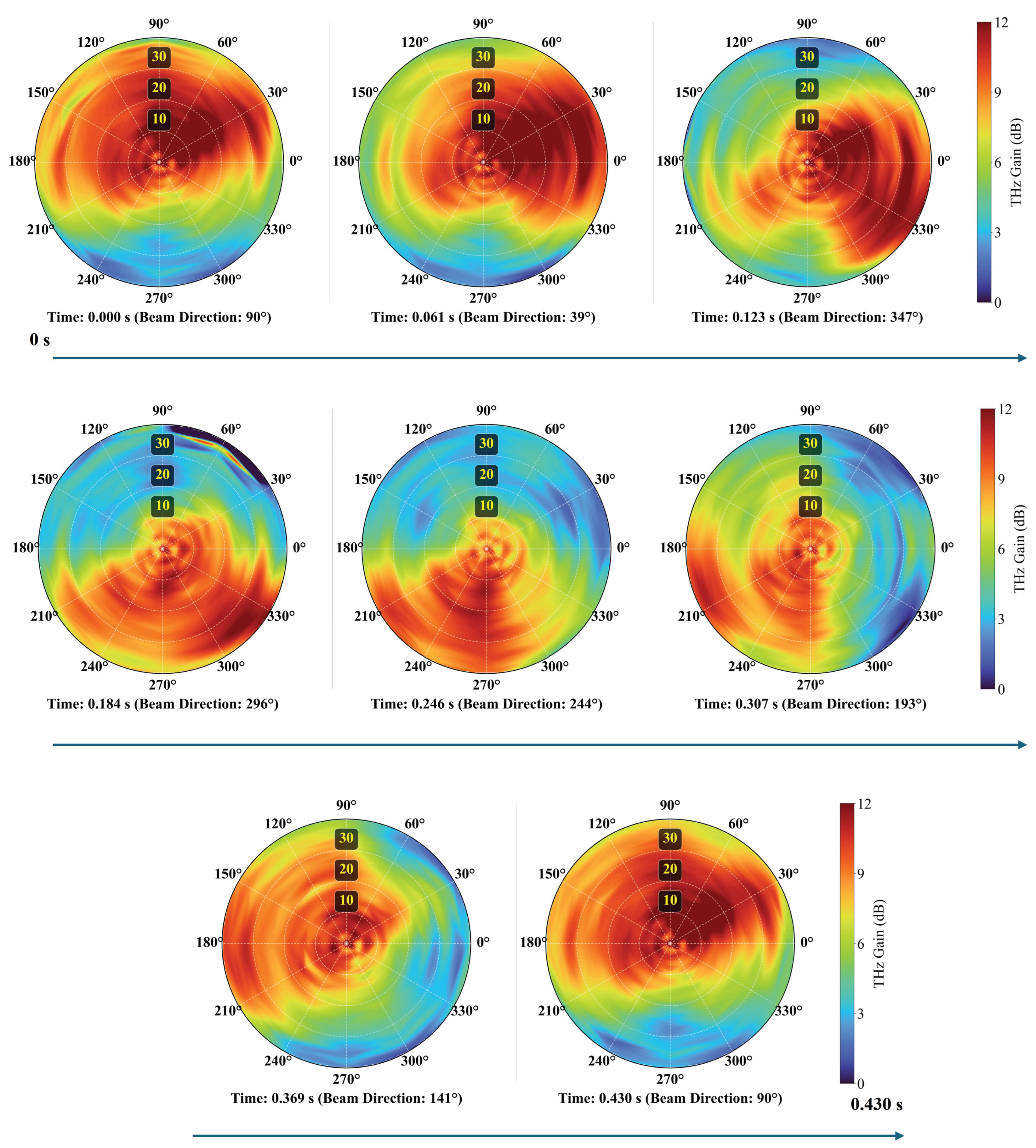
Figure 8 illustrates the dynamic 2D beam scanning capability of the proposed 2×2 array. In this experiment, the OPA phases are continuously updated to steer the main beam along a constant-polar circle at a commanded polar angle of , while the azimuth angle is swept over – within approximately 0.43 s. To quantify the beam stability during scanning, we evaluated the THz gain at the receiver position at , and at the azimuth index closest to the commanded beam direction at each time step. Over one full rotation (corresponding to an average scan rate of 2.32 Hz), the THz gain at the commanded direction has an average value of 9.67 dB with a standard deviation of 1.93 dB and varies between 5.24 dB and 12.22 dB. The fraction of samples with THz gain dB is 66.7%, indicating that the beam intensity in the commanded direction is maintained above 9 dB for most of the scan. These results demonstrate that the proposed system can perform fast scanning at around 2.3 Hz while preserving a well-defined main lobe and reasonably stable gain over the full field of view.
5. Conclusion
In this paper, we have proposed and experimentally demonstrated an optoelectronic 2D THz phased-array transmitter. The transmitter is composed of four InGaAs/InP UTC-PDs that directly feed a MPA array on a low-loss SiC substrate, while the excitation phases of all MPAs are generated and controlled in the optical domain by a silica-based OPA. We established the relationship between the OPA-controlled phase steps and the desired 2D steering angles, providing a clear design framework for phase programming in polar and azimuth. Measurements of each single MPA confirmed that all four MPAs share similar 2D radiation patterns, allowing the array to act as a nearly uniform aperture. By programming the OPA phases, we demonstrated 2D beam steering and 2D beam hopping among three representative directions at a polar angle of with azimuth angles of , , and , in good agreement with the calculated array factors. Furthermore, 2D beam scanning along a constant-polar circle at was realized, achieving a full azimuth sweep within 0.43 s while maintaining a well-defined main lobe and stable peak gain.
These results validate that the proposed 2×2 MPA array provides a compact and flexible platform for 2D THz beam manipulation at 300 GHz. The combination of direct UTC-PD feeding, SiC-based patch antennas, and OPA-enabled phase generation offers a scalable route toward larger arrays, wider steering ranges, and faster beam reconfiguration. Future work will focus on increasing the number of MPAs, integrating higher-speed phase shifters, and demonstrating high-capacity THz wireless links and imaging systems that leverage the demonstrated 2D beam steering, hopping, and scanning capabilities.
Author Contributions
Conceptualization, B.L.; methodology, B.L. and H.S.; software, B.L.; validation, B.L., Y.L. and M.C.; formal analysis, B.L.; investigation, B.L., Y.L. and H.S.; resources, H.S. and K.K.; data curation, B.L. and Y.L.; writing—original draft preparation, B.L.; writing—review and editing, B.L., Y.L., M.C. and S.Y.; visualization, B.L., M.C and S.Y.; supervision, M.C., Y.M. and K.K.; project administration, K.K.; funding acquisition, K.K. All authors have read and agreed to the published version of the manuscript.
Funding
This work was supported by the commissioned research by the MIC/FORWARD (JPMI241010003), the National Institute of Information and Communications Technology (NICT) JPJ012368C02801, JPJ012368C00901, JSPS KAKENHI Grant Numbers: JP23K17751, JP24H00319, JP24K17324, JP25K22089 and JST SPRING, Grant Number JPMJSP2136.
References
- Nagatsuma, T.; Ducournau, G.; Renaud, C.C. Advances in terahertz communications accelerated by photonics. Nature Photonics 2016, 10, 371–379. [Google Scholar] [CrossRef]
- Dhillon, S.; Vitiello, M.; Linfield, E.; Davies, A.; Hoffmann, M.C.; Booske, J.; Paoloni, C.; Gensch, M.; Weightman, P.; Williams, G.; et al. The 2017 terahertz science and technology roadmap. Journal of Physics D: Applied Physics 2017, 50, 043001. [Google Scholar] [CrossRef]
- Song, H.J.; Nagatsuma, T. Present and future of terahertz communications. IEEE transactions on terahertz science and technology 2011, 1, 256–263. [Google Scholar] [CrossRef]
- Jiang, W.; Zhou, Q.; He, J.; Habibi, M.A.; Melnyk, S.; El-Absi, M.; Han, B.; Di Renzo, M.; Schotten, H.D.; Luo, F.L.; et al. Terahertz communications and sensing for 6G and beyond: A comprehensive review. IEEE Communications Surveys & Tutorials 2024, 26, 2326–2381. [Google Scholar] [CrossRef]
- Xie, J.; Ye, W.; Zhou, L.; Guo, X.; Zang, X.; Chen, L.; Zhu, Y. A review on terahertz technologies accelerated by silicon photonics. Nanomaterials 2021, 11, 1646. [Google Scholar] [CrossRef]
- Maekawa, K.; Nakashita, T.; Yoshioka, T.; Hori, T.; Rolland, A.; Nagatsuma, T. Single-channel 240-Gbit/s sub-THz wireless communications using ultra-low phase noise receiver. IEICE Electronics Express 2024, 21, 20230584–20230584. [Google Scholar] [CrossRef]
- Li, W.; Yu, J.; Zhu, B.; Zhang, J.; Zhu, M.; Zhao, F.; Xie, T.; Wang, K.; Wei, Y.; Yang, X.; et al. Photonics-assisted 320 GHz THz-band 50 Gbit/s signal outdoor wireless communication over 850 meters. In Proceedings of the 2023 Optical Fiber Communications Conference and Exhibition (OFC). IEEE, 2023, pp. 1–3.
- Wei, Y.; Yu, J.; Zhao, X.; Yang, X.; Wang, M.; Li, W.; Tian, P.; Han, Y.; Zhang, Q.; Tan, J.; et al. Demonstration of a photonics-aided 4,600-m wireless transmission system in the sub-THz band. Journal of Lightwave Technology 2024. [Google Scholar] [CrossRef]
- Mittleman, D.M. Twenty years of terahertz imaging. Optics express 2018, 26, 9417–9431. [Google Scholar] [CrossRef]
- Series, P. Attenuation by atmospheric gases and related effects. Technical report, 2019.
- Headland, D.; Monnai, Y.; Abbott, D.; Fumeaux, C.; Withayachumnankul, W. Tutorial: Terahertz beamforming, from concepts to realizations. Apl Photonics 2018, 3. [Google Scholar] [CrossRef]
- Monnai, Y.; Lu, X.; Sengupta, K. Terahertz beam steering: from fundamentals to applications. Journal of Infrared, Millimeter, and Terahertz Waves 2023, 44, 169–211. [Google Scholar] [CrossRef]
- Sengupta, K.; Nagatsuma, T.; Mittleman, D.M. Terahertz integrated electronic and hybrid electronic–photonic systems. Nature Electronics 2018, 1, 622–635. [Google Scholar] [CrossRef]
- Zhuang, X.; Zhang, W.; Wang, K.; Gu, Y.; An, Y.; Zhang, X.; Gu, J.; Luo, D.; Han, J.; Zhang, W. Active terahertz beam steering based on mechanical deformation of liquid crystal elastomer metasurface. Light: Science & Applications 2023, 12, 14. [Google Scholar] [CrossRef] [PubMed]
- Balanis, C.A. Antenna theory: analysis and design; John wiley & sons, 2016.
- Capmany, J.; Novak, D. Microwave photonics combines two worlds. Nature photonics 2007, 1, 319. [Google Scholar] [CrossRef]
- Che, M.; Kondo, K.; Doi, R.; Kato, K. Demonstration of optoelectronic-phased-array driven THz-wave power combination and beam steering. In Proceedings of the Optical Fiber Communication Conference. Optica Publishing Group, 2023, pp. M3D–4.
- Che, M.; Nishiyama, N.; Yamauchi, K.; Kuboki, T.; Ito, H.; Ishibashi, T.; Kato, K. 450-GHz-wave beam-steering with 1 kHz repetition by optical phase control. In Proceedings of the 45th European Conference on Optical Communication (ECOC 2019). IET, 2019, pp. 1–3.
- Li, B.; Che, M.; Ye, S.; Yang, D.; Tang, H.; Mikami, Y.; Kato, K. Photonic-Assisted Frequency-independent Beam Steering for Wideband Terahertz Wireless Applications. Journal of Lightwave Technology 2025. [Google Scholar]
- Li, B.; Che, M.; Ye, S.; Mikami, Y.; Kato, K. Demonstration of Optoelectronic THz Beam Tracking Using Real-time Phase Optimization. IEEE Photonics Technology Letters 2025. [Google Scholar] [CrossRef]
- Murano, K.; Watanabe, I.; Kasamatsu, A.; Suzuki, S.; Asada, M.; Withayachumnankul, W.; Tanaka, T.; Monnai, Y. Low-profile terahertz radar based on broadband leaky-wave beam steering. IEEE Transactions on Terahertz Science and Technology 2016, 7, 60–69. [Google Scholar] [CrossRef]
- Yao, S.S.; Cheng, Y.J.; Wu, Y.F.; Yang, H.N. THz 2-D frequency scanning planar integrated array antenna with improved efficiency. IEEE Antennas and Wireless Propagation Letters 2021, 20, 983–987. [Google Scholar] [CrossRef]
- Sato, K.; Monnai, Y. Terahertz beam steering based on trajectory deflection in dielectric-free Luneburg lens. IEEE Transactions on Terahertz Science and Technology 2020, 10, 229–236. [Google Scholar] [CrossRef]
- Sato, K.; Monnai, Y. Two-dimensional terahertz beam steering based on trajectory deflection of leaky-mode. IEEE Transactions on Terahertz Science and Technology 2021, 11, 676–683. [Google Scholar] [CrossRef]
- Cai, M.; Gao, K.; Nie, D.; Hochwald, B.; Laneman, J.N.; Huang, H.; Liu, K. Effect of wideband beam squint on codebook design in phased-array wireless systems. In Proceedings of the 2016 IEEE Global Communications Conference (GLOBECOM). IEEE, 2016, pp. 1–6.
- Ishibashi, T.; Ito, H. Uni-traveling-carrier photodiodes. Journal of Applied Physics 2020, 127. [Google Scholar]
- Rouvalis, E.; Renaud, C.C.; Moodie, D.G.; Robertson, M.J.; Seeds, A.J. Traveling-wave uni-traveling carrier photodiodes for continuous wave THz generation. Optics Express 2010, 18, 11105–11110. [Google Scholar] [CrossRef]
- Song, H.J.; Ajito, K.; Muramoto, Y.; Wakatsuki, A.; Nagatsuma, T.; Kukutsu, N. Uni-travelling-carrier photodiode module generating 300 GHz power greater than 1 mW. IEEE Microwave and Wireless Components Letters 2012, 22, 363–365. [Google Scholar] [CrossRef]
- Kato, K. Terahertz-wave beam control by photonics technology. In Proceedings of the Terahertz Emitters, Receivers, and Applications XI. SPIE, 2020, Vol. 11499, p. 1149902.
- Takahashi, H. Planar lightwave circuit devices for optical communication: present and future. In Proceedings of the Active and Passive Optical Components for WDM Communications III. SPIE, 2003, Vol. 5246, pp. 520–531.
- Harris, N.C.; Ma, Y.; Mower, J.; Baehr-Jones, T.; Englund, D.; Hochberg, M.; Galland, C. Efficient, compact and low loss thermo-optic phase shifter in silicon. Optics express 2014, 22, 10487–10493. [Google Scholar] [CrossRef]
- Che, M.; Kamiura, Y.; Doi, R.; Ssali, H.; Agemori, H.; Li, B.; Kato, K. On-Chip 300-GHz-Band Power Combining with Arrayed InGaAs UTC-PDs and Corporate-Fed 2× 2 MPA on SiC Substrate for Wireless Communication. In Proceedings of the 2024 IEEE Asia-Pacific Microwave Conference (APMC). IEEE, 2024, pp. 4–6.
- Nagatsuma, T.; Ohara, T.; Kawamoto, Y.; Maekawa, K.; Ishibashi, T. SiC-substrate uni-traveling-carrier photodiode modules for 300-GHz-band wireless communications. In Proceedings of the 2024 49th International Conference on Infrared, Millimeter, and Terahertz Waves (IRMMW-THz). IEEE, 2024, pp. 1–2.
- Cheng, Z.; Liang, J.; Kawamura, K.; Zhou, H.; Asamura, H.; Uratani, H.; Tiwari, J.; Graham, S.; Ohno, Y.; Nagai, Y.; et al. High thermal conductivity in wafer-scale cubic silicon carbide crystals. Nature communications 2022, 13, 7201. [Google Scholar] [CrossRef] [PubMed]
- Ito, H.; Ishibashi, T. Fermi-level managed barrier diode for broadband and low-noise terahertz-wave detection. Electronics Letters 2015, 51, 1440–1442. [Google Scholar] [CrossRef]
- Ito, H.; Ishibashi, T. Low-noise heterodyne detection of terahertz waves at room temperature using zero-biased Fermi-level managed barrier diode. Electronics Letters 2018, 54, 1080–1082. [Google Scholar] [CrossRef]
- Ito, H.; Ishibashi, T. Broadband and high-sensitivity terahertz-wave detection using Fermi-level managed barrier diode. In Proceedings of the Terahertz Physics, Devices, and Systems X: Advanced Applications in Industry and Defense. SPIE, 2016, Vol. 9856, pp. 83–90.
Figure 1.
Concept of the proposed optoelectronic 2×2 MPA array enabling 2D beam steering in polar and azimuth .
Figure 1.
Concept of the proposed optoelectronic 2×2 MPA array enabling 2D beam steering in polar and azimuth .
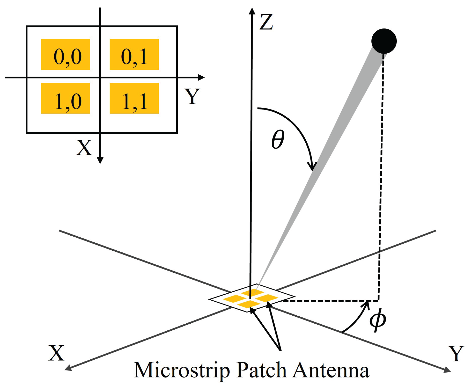
Figure 2.
(a) Top view and (b) cross-sectional view along A– of the developed THz chip, where a MPA array is directly fed by four UTC-PDs on a SiC substrate.
Figure 2.
(a) Top view and (b) cross-sectional view along A– of the developed THz chip, where a MPA array is directly fed by four UTC-PDs on a SiC substrate.
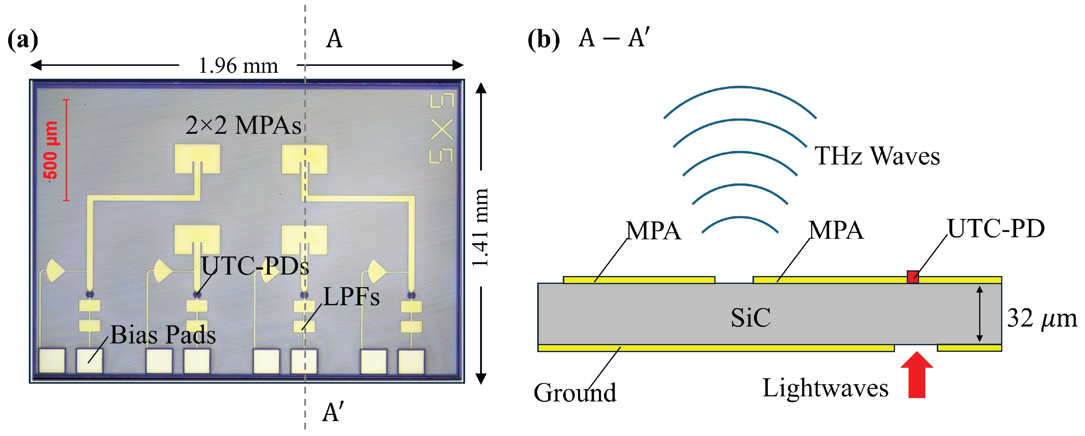
Figure 3.
(a) Schematic and (b) photograph of the silica-based OPA with thermo-optic phase shifters.
Figure 3.
(a) Schematic and (b) photograph of the silica-based OPA with thermo-optic phase shifters.
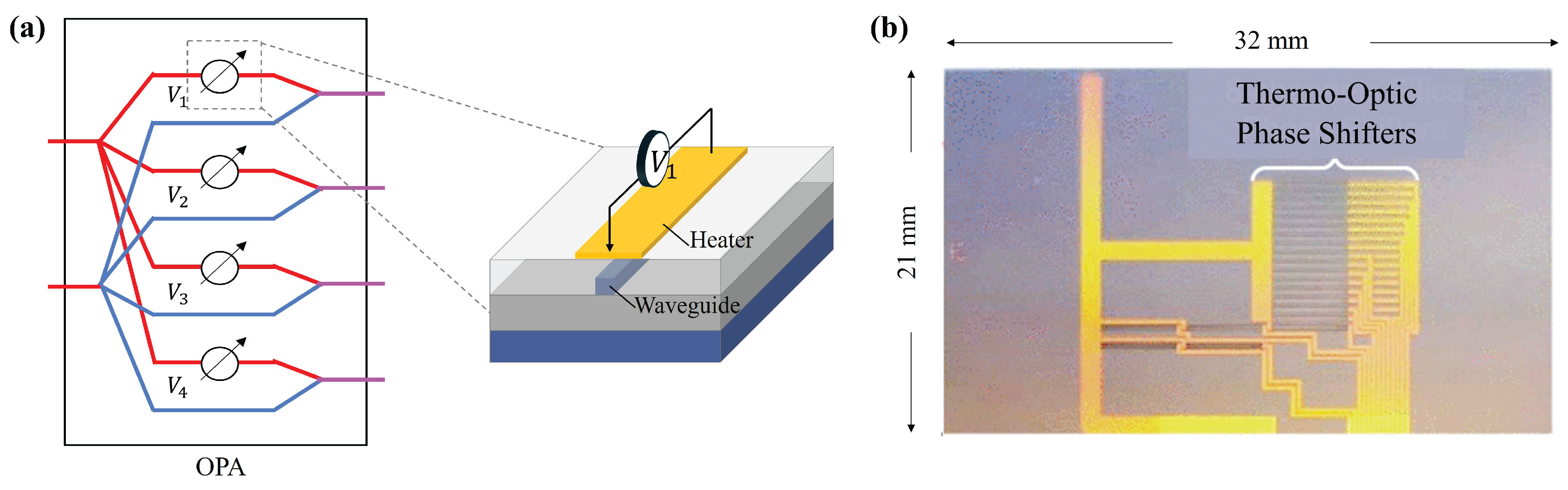
Figure 4.
Experimental setup for demonstrating 2D THz beam steering with the proposed optoelectronic 2×2 MPA array.
Figure 4.
Experimental setup for demonstrating 2D THz beam steering with the proposed optoelectronic 2×2 MPA array.
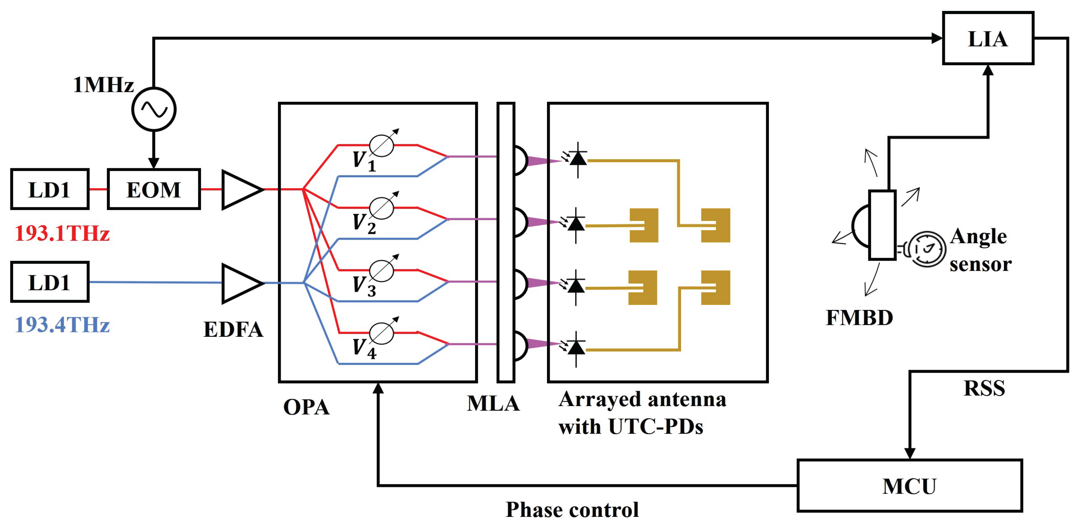
Figure 5.
Measured normalized 2D radiation patterns of the four THz MPAs: (a)–(d) correspond to MPA {0,0}–{1,1}.
Figure 5.
Measured normalized 2D radiation patterns of the four THz MPAs: (a)–(d) correspond to MPA {0,0}–{1,1}.
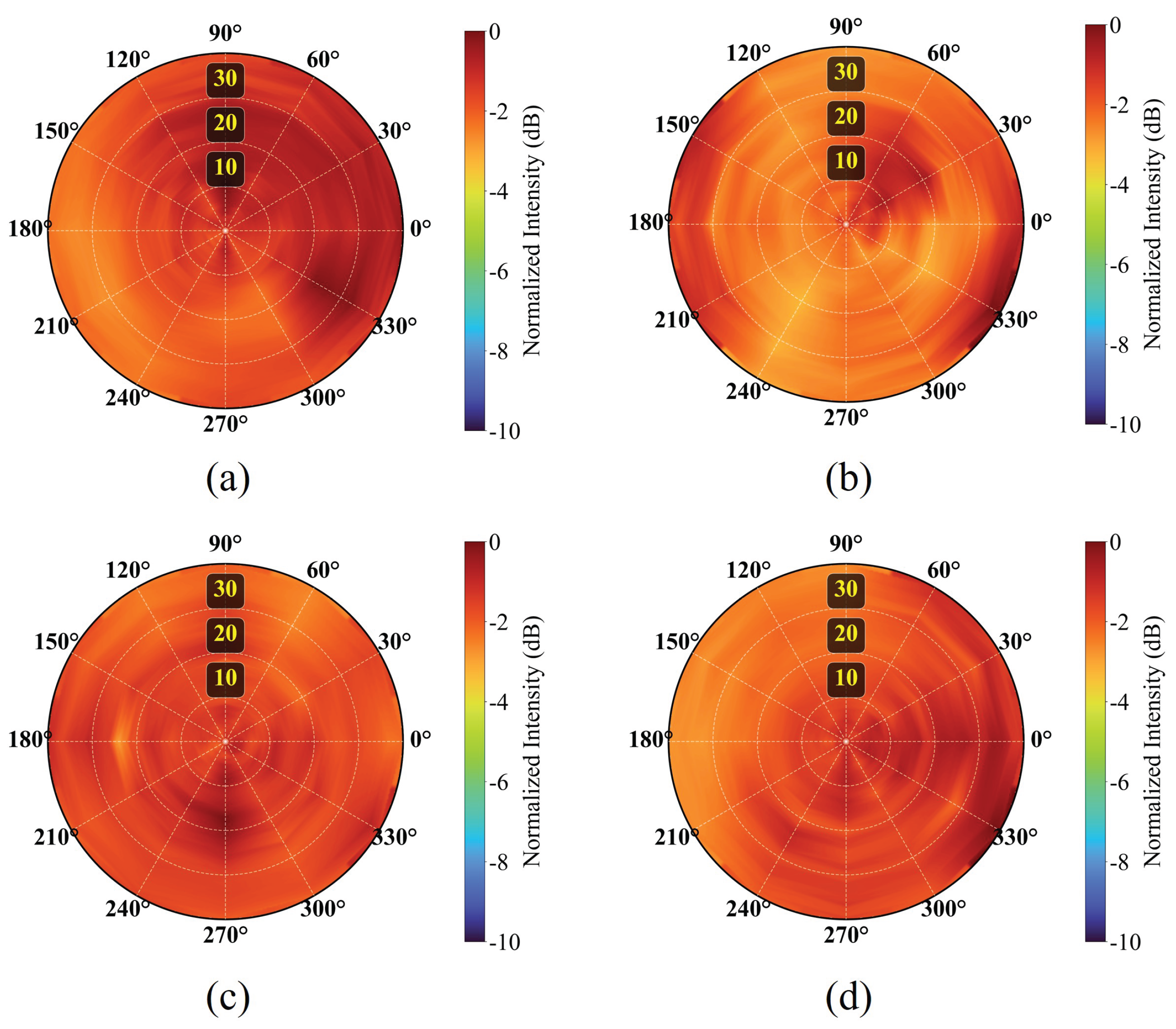
Figure 6.
Measured 2D beam patterns of the proposed 2×2 THz array for different steering angles. (a)–(c) correspond to target beam directions of , , and , respectively.
Figure 6.
Measured 2D beam patterns of the proposed 2×2 THz array for different steering angles. (a)–(c) correspond to target beam directions of , , and , respectively.
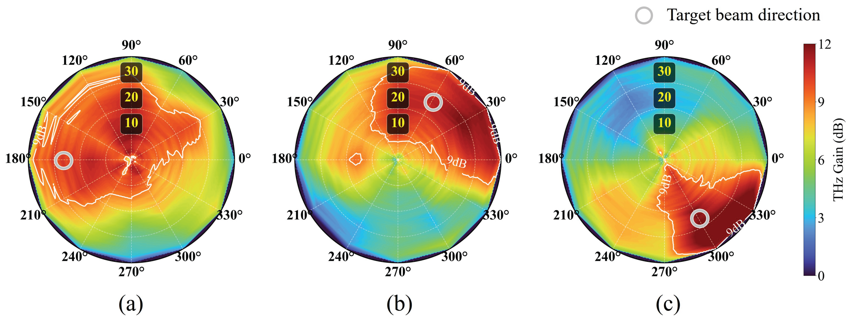
Figure 7.
Measured THz gain as a function of time during beam hopping among three 2D target directions .
Figure 7.
Measured THz gain as a function of time during beam hopping among three 2D target directions .
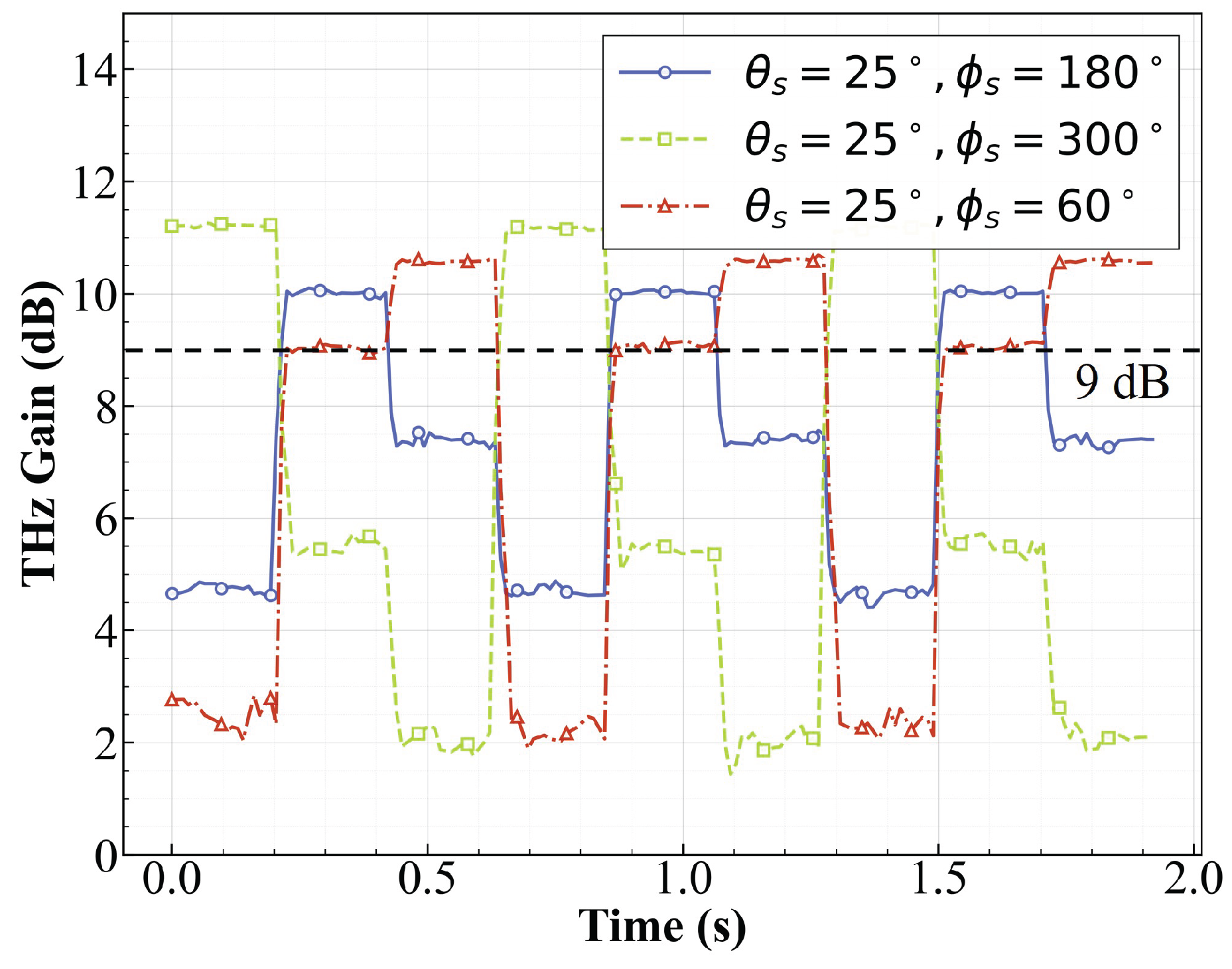
Figure 8.
Time-resolved 2D beam patterns during scanning with the proposed optoelectronic 2×2 MPA array.
Figure 8.
Time-resolved 2D beam patterns during scanning with the proposed optoelectronic 2×2 MPA array.
Disclaimer/Publisher’s Note: The statements, opinions and data contained in all publications are solely those of the individual author(s) and contributor(s) and not of MDPI and/or the editor(s). MDPI and/or the editor(s) disclaim responsibility for any injury to people or property resulting from any ideas, methods, instructions or products referred to in the content. |
© 2025 by the authors. Licensee MDPI, Basel, Switzerland. This article is an open access article distributed under the terms and conditions of the Creative Commons Attribution (CC BY) license (http://creativecommons.org/licenses/by/4.0/).
Copyright: This open access article is published under a Creative Commons CC BY 4.0 license, which permit the free download, distribution, and reuse, provided that the author and preprint are cited in any reuse.


