
Submitted:
19 November 2025
Posted:
21 November 2025
You are already at the latest version
Abstract
Metal-based electrical contact materials (ECMs) are essential in switching devices and rotating electrical machines, where sliding contacts enable reliable current transmission under motion. These materials must exhibit high conductivity, low friction, and wear resistance to meet industrial demands. However, their reliability is limited by wear, oxidation, arcing, and other failure mechanisms that increase contact resistance and degrade performance. To address these issues, researchers have developed self-lubricating metal matrix composites (MMCs), particularly copper (Cu) and silver (Ag)-based composites reinforced with solid lubricants such as molybdenum disulfide, tungsten disulfide, graphite, carbon nanotubes, graphene and its derivatives. While Cu and Ag provide excellent conductivity, each has trade-offs in cost, oxidation resistance, and mechanical strength. Strategies for improving reliability involve material optimization, surface treatments, lubrication, contact design modifications, and advanced manufacturing. Although MMCs are widely reviewed, self-lubricating Ag matrix nanocomposites (AgMNCs) for sliding contacts are under-explored. This review highlights recent progress in AgMNCs produced by conventional or modern powder metallurgy techniques, focusing on the role of solid lubricants, testing conditions, and microstructure on tribological performance. Wear mechanisms, research gaps, and future directions are discussed, highlighting pathways toward the development of reliable sliding contacts.
Keywords:
self-lubricating silver matrix composites
; solid lubricants
; powder metallurgy
; hot pressing sintering
; spark plasma sintering
; friction
; wear
; sliding contacts
1. Introduction
Metal-based electrical contact materials (ECMs) are commonly used in switching devices such as circuit breakers, contactors, and relays [1,2,3,4]. ECMs facilitate the conduction of electrical current between stationary and moving contact elements. An ideal ECM should provide low, stable electrical contact resistance (ECR), high electrical and thermal conductivity, sufficient hardness and strength, and strong resistance to arcing, wear, oxidation, and chemical degradation [1,2,3,4]. These properties are critical for ensuring the performance, reliability, and service life of electrical contacts [5].
Sliding ECMs constitute a specialized class of contact materials engineered to maintain reliable electrical connectivity under conditions of relative motion between contact surfaces. In addition to fulfilling the general performance criteria of conventional ECMs, sliding ECMs must also exhibit excellent self-lubricating properties to minimize friction and wear during operation [2].
Sliding electrical contacts (SECs) enable power and signal transmission between stationary and moving components in electrical machines and devices. Their performance is critical to system reliability, efficiency, and stability. SECs used in industrial applications such as railway pantographs, generator switches, slip rings, and brushes in motors, alternators, electric vehicles, and household appliances must meet strict requirements [5,6,7,8]. The ECMs at the contact interface must provide high conductivity, low friction, good wear resistance, low contact resistance, and stable transmission.
With the growing adoption of SECs in emerging applications, contact failures have become an increasingly prominent concern in both academic research and industrial practice [7,9]. Main failure factors affecting sliding current-collecting assemblies of urban electric transport are displayed in Figure 1 [9].
Failure mechanisms include wear, friction, oxidation, corrosion, contamination, high current loads, arcing, and mechanical or thermal stresses. These factors increase contact resistance, promote oxide layer formation, lower conductivity, and reduce reliability. To improve performance, researchers apply strategies such as material optimization, surface treatments, design modifications, and advanced manufacturing [1,10].
Although SECs are designed for low friction and wear, they often face harsher mechanical and electrical stresses than non-electrical sliding contacts, leading to intermittent failures, shorter service life, and possible short circuits from wear debris [8,11]. To ensure stable current transmission and low contact resistance, highly conductive materials such as copper (Cu), silver (Ag), and metal matrix composites (MMCs) are commonly used. Both Cu and Ag are soft, highly conductive metals owing to their malleability and ductility [1]. However, Cu is prone to oxidation, whereas Ag provides superior oxidation resistance at a higher cost [12]. In their pure forms, both metals exhibit relatively low wear resistance, but Cu provides slightly better mechanical durability [1]. Despite advances in material selection, wear continues to be a major challenge, significantly affecting the durability and electrical performance of SECs.
Self-lubricating MMCs are advanced materials consisting of a metal matrix, such as Cu [13], Ag [6], or Ag-Cu [14], reinforced with solid lubricants. These lubricants include molybdenum/tungsten disulfide (MoS2/WS2) [15,16,17,18], graphite [19], single-walled/multi-walled carbon nanotubes (SWCNTs/MWCNTs) [20,21,22,23], graphene (Gr), graphene oxide (GO), reduced GO (rGO) [24,25,26], hexagonal black phosphorus (h-BP) [27], or other functional additives and hybrid fillers [6,28,29,30,31,32].
Cu- and Ag-based composites exhibit excellent electrical and thermal conductivity, enabling incorporation of semiconductive phases [15]. As soft metals with multiple slip planes, they resist significant work hardening during sliding. Ag is the most widely used solid lubricant in self-lubricating materials with intermetallic or metal matrix (e.g. Ni3Al, TiAl, and NiAl) for extreme-condition applications [12], owing to its superior oxidation resistance, high thermal conductivity, and low coefficient of friction, which facilitate efficient heat dissipation during operation [12]. Furthermore, Ag exhibits excellent lubrication performance below 500°C due to its high diffusion rate and facile tribolayer formation at the sliding interface, which are key mechanisms enabling self-lubrication [12].
Self-lubricating MMCs demonstrate excellent tribological performance by releasing solid lubricants from the metal matrix, which form a lubricating film on the tribosurface. This film acts as a protective layer, preventing direct contact between mating surfaces under load [15,28]. These materials also exhibit a self-replenishing mechanism, continuously supplying lubricant to the surface and maintaining effective lubrication during prolonged operation [28,33]. Self-lubricating MMCs are widely utilized in SECs for various industrial applications due to their low friction and wear characteristics [6,7,28].
The properties of self-lubricating MMCs, such as density, coefficient of friction (COF), wear resistance, mechanical strength, stiffness, hardness, electrical and thermal conductivity, and coefficient of thermal expansion (CTE), are significantly influenced by microstructural uniformity and the type, size, shape, concentration, and distribution of reinforcing additives [16]. Furthermore, the tribological performance of SECs is governed not only by material properties but also by test conditions (e.g., load, sliding speed, sliding distance, electrical current, temperature, and lubrication) [34,35].
Conventional Cu-based SECs typically exhibit a COF of 0.2–0.4, depending on test conditions [35]. Although copper was not initially classified as a Critical Raw Material (CRM), it was designated a Strategic Raw Material (SRM) by the European Commission in the fifth CRM list for the European Union, published in 2023 [36]. This reclassification highlights copper's essential role, with global consumption of about 20 Mt in 2020 due to the increasing electrification of strategic technologies [36]. Concerns over long-term supply further challenge its use. Silver (Ag), a precious metal not classified as CRM or SRM, has emerged as a promising alternative for Cu in SECs. Furthermore, the global MMC market is projected to grow by approximately 1.76 times between 2020 and 2025, driven by increasing demand for MMC components across strategic industries [37].
Numerous reviews on self-lubricating MMCs have been published to date [26,38]. However, a comprehensive review specifically focused on self-lubricating silver-based metal matrix nanocomposites (AgMNCs) for sliding contact applications is still unexplored. To address this gap, the present review synthesizes key findings from recent studies on self-lubricating AgMNCs produced using conventional or advanced powder metallurgy (PM) techniques. It outlines the effects of solid lubricants and testing conditions on the tribological performance and wear mechanisms of AgMNC-based sliding contacts. In addition, this review highlights current research gaps and proposes future directions for enhancing the reliability of sliding contact systems through both experimental and numerical approaches. By addressing existing challenges, the article aims to provide useful insights for researchers and industry professionals engaged in the development of advanced sliding electrical contact materials.
2. Methodology
The literature search was systematically performed in the Scopus database, following the principles outlined in the PRISMA 2020 framework [39]. To ensure comprehensive coverage, the electronic search was supplemented by a manual screening of relevant references, with search keywords tailored to the specific sections of this review.
The search strategy used the following combination of keywords: ("silver matrix composite" OR "Ag-based composite" OR "Ag metal nanocomposite" OR "Ag-MoS₂" OR "Ag-WS₂" OR "Ag-graphene" OR "Ag-CNTs") AND ("self-lubricating" OR "tribology" OR "friction" OR "wear" OR "electrical contact") AND ("powder metallurgy" OR "spark plasma sintering" OR "hot pressing"). The initial search retrieved 69 records. After applying inclusion filters to retain only articles (52), conference papers (3), and reviews (1) published in English, a total of 56 records remained. These studies met the eligibility criteria and were included in the qualitative synthesis presented in this review.
The keyword co-occurrence network (Figure 2) highlights four major research directions in the field of silver-based self-lubricating composites. The blue cluster focuses on electrical contacts, arc erosion, and powder metallurgy, reflecting application-oriented studies on electrical performance. The green cluster groups keywords such as silver matrix composites, graphene, spark plasma sintering, and hot pressing, emphasizing material processing, fabrication techniques and main properties of silver matrix composites. The red cluster gathers terms related to tribology, friction, wear resistance, and molybdenum/tungsten compounds, showing the strong research interest in tribological behavior and lubrication mechanisms. Finally, the yellow transition zone links structural and mechanical aspects, such as hardness, reinforcement, and thermal conductivity, to the other clusters.
3. Common Solid Lubricants Used in AgMCs and AgMNCs
Solid lubricants are typically two-dimensional (2D) materials with a lamellar crystal structure, featuring strong covalent bonds within the layers and weak van der Waals interactions between them [26,27,40]. Most 2D materials, such as MoS2 and WS2 transition metal dichalcogenides (TMDs), as well as graphite and graphene, exhibit minimal in-plane anisotropy, allowing their layers to shear easily [6,27]. This structural anisotropy enables smooth sliding between lamellae and contributes to their self-lubricating behavior [6]. Furthermore, AgMCs and AgMNCs incorporating binary solid lubricants (e.g., combinations of MoS₂ and WS₂ [29], or graphite and MoS₂ [41]), or hybrid fillers (e.g., silver nanoparticles (AgNPs) deposited on carbon nanotubes (Ag@CNTs) [42,43], or AgNPs doped graphene nanosheets (Ag@GNs) [31] have proved superior self-lubricating performance compared to those reinforced with a single solid lubricant.
Common solid lubricants used in AgMCs and AgMNCs and their key benefits are summarized in Table 1.
Comprehensive discussions of the characteristics, tribological behavior, and frictional mechanisms of the solid lubricants listed in Table 1 can be found in several review articles [12,16,20,25,26,27,30,40,47,48].
The fundamental origins of friction between sliding bodies are commonly explained by models such as Prandtl-Tomlinson (PT) [49,50] and Frenkel-Kontorova (FK) [50,51]. Both PT and FK models describe the one-dimensional motion of surface atoms, attributing friction to the energy required for atomic hopping across a periodic potential [50].
The nanoscale interfacial and surface friction mechanisms of 2D layered materials are schematically shown in Figure 3 [47], where SLG denotes single-layer graphene, BLG denotes bilayer graphene, and TTM refers to the two-temperature method. It is worth noting that the correct designations of the models are Prandtl-Tomlinson [49,50] and Frenkel-Kontorova [50,51], rather than the Tomlinson and Frenkel-Fontorova models.
As illustrated in Figure 3, the friction mechanisms in 2D layered materials arise from the weak van der Waals interactions between adjacent layers, which facilitate interlayer shear, and yield a low shear strength. Load-dependent adhesion and energy dissipation at the sliding interface strongly influence the frictional behavior at the atomic scale [50,52]. Key factors such as interface geometry, sliding speed, tribo-system temperature, testing duration, and interfacial chemistry, govern the relationship between the applied normal load and the resulting frictional forces [52]. These atomic-scale friction mechanisms promote the exceptional lubricity of 2D layered materials and are essential to their performance when incorporated into Ag-based composites for sliding electrical contacts.
4. Preparation of Powder Mixtures and Sintered AgMNCs
Self-lubricating MMCs, including AgMCs and AgMNCs, can be produced through conventional or advanced powder metallurgy (PM) techniques using powder mixtures composed of Ag and either single or binary solid lubricants, or hybrid fillers.
4.1. Common Preparation Methods of AgMNC Powder Mixtures
The microstructural homogeneity and performance of sintered AgMNCs produced through PM techniques are highly dependent on the properties of the initial raw powders, such as particle shape, particle size distribution, and purity, and the nature and content of the constituent elements, as well as the characteristics of the resulting AgMNC powders. Furthermore, the choice of powder mixing techniques, surface functionalization strategies, and processing parameters, such as type, shape, and capacity of the synthesis vessels or milling jars and balls, mixing time, mixing speed, and the motion of the driving system, ball-to-powder ratio (BPR) greatly significantly affects the quality of the final powder mixtures [42,53].
AgMNC powders can be synthesized at both laboratory and industrial scales using either mechanical or chemical methods.
4.1.1. Mechanical Methods for Preparation of AgMNC Powders
Mechanical methods for preparation of AgMNC powders involve the homogenization of constituent powders using mixing-shaking devices or ball mills for blending and fine grinding. Among these, planetary ball milling (PBM) is the most commonly employed technique for the preparation of AgMNC powders [54]. In addition to PBM, high-energy ball milling (HEBM) and solution ball milling (SBM) are sometimes utilized. These mechanical methods induce physical modifications in the powders without involving chemical reactions during powder blending and milling [54].
Each mechanical mixing technique presents specific advantages and limitations, as documented in the literature [54]. For instance, HEBM can achieve higher milling speeds and more effective structural refinement compared to lower-energy PBM processes. However, HEBM is rarely employed to produce AgMNC powders, as Ag and its alloys exhibit high ductility and malleability due to their inherently soft metallic nature [12,55].
Mechanical mixing (e.g., PBM, SBM) is widely used to produce micro- and nanocomposite mixtures. However, it is an intensive process involving heat, deformation, and crystallization, which can degrade carbon-based nanomaterials (e.g., graphene, GO, CNTs) used as solid lubricants in AgMNCs. The large size mismatch between Ag powders and nanoscale reinforcements often leads to poor dispersion and agglomeration, resulting in reduced mechanical and thermal performance of the final composites [56].
Ball milling techniques, whether conducted under dry or wet conditions, often involves long processing times, as well as irregular particle shapes, broad particle size distributions, and significant strain hardening of the milled powders. Additionally, friction between the milling media (jars and balls) and powders can also introduce contamination [54]. Therefore, selecting a mixing method and processing parameters requires balancing these drawbacks to achieve the desired properties of the final powder mixtures.
Representative Examples of AgMNC Powders Fabricated by Mechanical Methods
Several studies [6,29,44,57] reported the preparation of AgMNC powders composed of Ag nanopowder (d50 = 53−75 nm), 10 wt.%WS2 (d50 = 36−82 nm), and 5−10 wt.%MoS2 (d50 = 2−3.5 μm) using similar BPM processes. These studies typically specify milling conditions such as duration (24 h), speed (120 rpm), and the use of a high-purity (99.99%) nitrogen atmosphere. Other key parameters, such as the material and diameter of the milling balls, the material and volume of the milling jars, and the ball-to-powder ratio, are often not reported, as the primary focus of these investigations is to examine the tribological behavior, self-lubricating performance, and wear resistance mechanisms of sintered AgMNCs used as sliding ECMs working under high-purity nitrogen or high vacuum environments.
Limited details regarding milling conditions and characterization of the milled powders are noted in several other studies [18,43]. For example, Sun et al. [18] prepared AgMNC powders with a composition of Ag-30 vol.%WS2 by ball milling a slurry consisting of 8 vol.% Ag-WS2 and 3 wt.% gelatin (used as an organic binder) in distilled water for 12 h at 100 rpm. The starting materials included irregularly shaped Ag powder (d50 = 200 nm, 99.9% purity) and WS2 flakes (d50 = 6 μm, 99% purity). However, details regarding the characteristics of the milled powders (e.g., size, shape, and particle size distribution) were not provided. This study primarily aimed to investigate the effect of WS₂ flake orientation on the tribological performance of sintered Ag-WS₂ composites.
Jia et al. [43] prepared CNTs/Ag and Ag@CNTs/Ag powders with 0%, 1%, 2.5%, and 5 % CNTs (vol. %) using SBM. AgNPs were uniformly deposited on MWCNTs (Dinner = 5–12 nm, Douter = 20–50 nm, L = 10–20 µm) via electroless plating assisted by ultrasonic spray atomization (EPUSA) to form Ag@CNTs. Subsequently, CNTs and Ag@CNTs were each mixed with Ag powders and pure ethanol to prepare a slurry, then milled in a planetary ball mill for 2 h at 300 rpm with a BPR of 10:1. After filtration and vacuum drying at 333 K for 12 h, the obtained flake composite powders were sintered via SPS or hot pressing (HP). SEM analysis of the milled CNTs/Ag powders (2.5 vol.% CNTs) showed persistent CNT agglomerates after SBM. In contrast, the milled Ag@CNTs/Ag powders (1–5 vol.% CNTs) exhibited well-dispersed Ag@CNTs embedded within the Ag matrix, with minor CNT clustering only at 5 vol.% CNTs. However, details on Ag powder size, milling ball type and size, and milled powder characteristics were not disclosed.
Zhao et al. [42] proved that combining EPUSA for Ag@CNTs formation with SBM processing helps prevent CNT structural damage and Ag powder cold-welding during ball milling, while enhancing interfacial bonding between Ag@CNTs and the Ag matrix. Ag@CNTs/Ag powders with 0%, 2.5%, 3.75%, and 5% volumetric contents of MWCNTs (Dinner = 5–12 nm, Douter = 20–50 nm, L = 10–20 µm) were produced by milling each slurry of Ag@CNTs and Ag powders in pure ethanol for 4 h at 300 rpm with a BPR of 10:1. After filtration and vacuum drying, flake composite powders were obtained and sintered via SPS. For comparison, Ag@CNTs/Ag powders were also prepared using conventional electroless plating (CEP), followed by SBM and SPS processing. SEM analysis of CEP-prepared powders containing 2.5 vol.% CNTs revealed Ag@CNTs agglomerates adhering to the surfaces of Ag particles. This behavior was attributed to the presence of AgNP lumps causing localized cold welding under mechanical force applied during processing. On the contrary, SEM images of EPUSA-prepared powders containing 2.5 vol.% CNTs showed well-dispersed Ag@CNTs embedded within the Ag matrix, as ball milling effectively broke up clusters.
Huang et al. [2] fabricated AgMNC powders reinforced with CNTs at volumetric concentrations of 0%, 6%, and 8%. The starting materials consisted of spherical Ag powders with diameters of 400–600 nm and CNTs with diameters of 30–50 nm and lengths of 10–20 μm. To enhance interfacial bonding between the CNTs and the Ag matrix, the CNT surfaces were electrochemically coated with a nickel (Ni) layer, resulting in an Ni content of approximately 10 wt.%. However, the study did not provide details regarding the electrochemical deposition conditions. The Ag powders and Ni-coated CNTs were subsequently blended in a planetary ball mill for 6 h at 300 rpm with a BPR of 10:1. Zirconia (ZrO2) ceramic balls were used as the milling media, though their diameter was not specified. In addition, the study did not report the characteristics of the milled powders.
4.1.2. Chemical Methods for Preparation of AgMNC Powders
Chemical methods for preparation of AgMNC powders are particularly effective in enhancing the dispersion of solid lubricants within the Ag matrix by enabling functionalization or chemical interactions among the constituent elements. Key approaches include solution mixing (SM) and molecular-level mixing (MLM), which may involve covalent or non-covalent functionalization and elemental doping [54,58]. Covalent functionalization adds functional groups like hydroxyl or carboxyl, forming chemical bonds that enhance lubricant dispersion in the Ag matrix. In contrast, non-covalent functionalization uses physical interactions (e.g., van der Waals forces, π-π stacking, surfactants) to form stable associations without chemical bonds [54]. Functionalization is essential for carbon-based nanomaterials (e.g., graphene, GO, rGO, CNTs) used as solid lubricants in MMCs like AgMNCs, as it prevents agglomeration and enhances performance [54,58]. Proper functionalization introduces surface chemical groups that improve interfacial bonding with the metal matrix, improving composite integrity and properties [54,58].
The MLM approach for synthesizing AgMNC powders involves forming a colloidal suspension of GO in an aqueous solution containing silver salt precursors such as silver nitrate (AgNO3). After precipitation and chemical reduction (e.g., with hydrazine or sodium borohydride, NaBH4), a homogeneous dispersion of rGO within Ag metal powder is obtained. Despite promising results, the use of strong reducing agents like hydrazine poses significant safety, toxicity, and environmental concerns, hindering large-scale application [56,59]. To address this, several studies have explored green and environmentally friendly alternatives for GO reduction, employing mild reductants such as ascorbic acid (C6H8O6), biological molecules (e.g., melatonin, green tea polyphenols, bacterial biomass), or plant extracts (e.g., Amaranthus hybridus) [56,59].
Representative Examples of AgMNC Powders Fabricated by Chemical Methods
Silvain et al. [56] employed a green MLM process to prepare AgMNC powders reinforced with 0.25–5 vol.% rGO. The Ag/rGO powders were synthesized from slurries containing GO (average lateral size = 5 μm, thickness = 5 nm) dispersed in deionized water. Each slurry was magnetically stirred for 5 min and sonicated for 1 h. Ascorbic acid (AA) was then added as a reducing agent, and the suspension was left to maturate for 1 h. An aqueous AgNO3 solution was rapidly added to initiate Ag+ ions reduction, followed by heating at 90°C for 1 h to facilitate GO reduction. The resulting Ag/rGO mixture was filtered, purified, and air-dried. For comparison, similar syntheses were conducted using hydrazine instead of AA. The powders were characterized by SEM, XRD, and Raman spectroscopy prior to hot pressing. SEM images of AA-prepared powders revealed spherical, monodisperse Ag particles (~2 μm) up to 3 vol.% rGO. At 5 vol.%, rGO, particles became smaller (~1 μm) and less spherical due to increased heterogeneous nucleation of Ag on GO. The autocatalytic reduction of Ag+ by AA, where Ag nuclei accelerate the reaction, explains the morphology changes with rGO content. Therefore, replacing hydrazine with AA yields comparable reduction and dispersion, while providing a safer, greener alternative.
Kang et al. [60] utilized a MLM process to prepare AgMNC powders having with a composition of Ag-10 wt.%WS2-5 wt.%MoS2. The NC powders were synthesized by sonicating for 1 h a slurry containing specified amounts of WS2 nanopowder (d50 = 50 nm), MoS2 powder (d50 = 2 μm), AgNO3, and deionized water. This was followed by chemical reduction of Ag+ ions to AgNPs using an aqueous NaBH4 solution (50 mmol/L), and subsequent purification and vacuum drying. Characterization of the synthesized AgMNC powders was conducted using transmission electron microscopy (TEM) prior to further consolidation by spark plasma sintering (SPS). The combined use of MLM and SPS enabled good interfacial bonding between the Ag matrix and the binary solid lubricants (WS₂ and MoS2), which contributed to the enhanced physical, mechanical, and triboelectrical performance of the self-lubricating AgMNCs.
Some studies [21,22] reported a modified MLM method to synthesize AgMNC powders reinforced with CNTs at volumetric concentrations of 0%, 1.5%, 3%, 4.5%, and 6% SWCNTs or MWCNTs [21], and 0%, 6%, and 12% MWCNTs [22]. The process involved non-covalent functionalization of SWCNTs (Daverage = 1–2 nm, L = 1–10 μm) and MWCNTs (Daverage = 4–12 nm, L = 15–30 μm) using surfactants such as sodium dodecyl sulfate (SDS) or sodium lauryl sulfate (SLS). CNTs were first dispersed in ethanol via sonication, followed by surfactant addition and further sonication for 2 h [22] or 4 h [21]. An aqueous AgNO3 solution was then added, stirred magnetically for 12 h, and reduced with hydrazine hydrate. The resulting solution was centrifuged at 2,000 rpm [21] or 5,000 rpm [22] for 5–10 min. The CNT/Ag precipitates were either washed with deionized water and air-dried [21], or air-dried and then washed to remove the surfactant [22]. The CNT/Ag nanopowders were analyzed by XRD, EDS, SEM, and HRTEM. Results confirmed uniform CNT dispersion and embedding in the Ag matrix, enabled by AgNP nucleation in stable CNT suspensions. XRD showed crystalline AgMNC powders with crystallite sizes of ~80 nm [21] and ~58 nm [22], strong Ag peaks, a low-intensity CNT peak, and no silver carbide (Ag4C3) formation. EDS detected carbon (C) and silver (Ag). SEM revealed well-dispersed CNTs at 1.5–3 vol.% [21], with some agglomeration at 6–12 vol.% [21,22]. HRTEM of CNT/Ag powders with 1.5 vol.% CNTs showed AgNPs bonded to CNT surfaces, not internal cavities [21]. Selected area diffraction pattern (SAED) confirmed Ag presence on CNT surfaces, without impurities or oxides. These results highlight that optimized synthesis and functionalization improve CNT dispersion at 3–6 vol.% in Ag.
As noted above, most studies in the literature do not provide detailed properties of mechanically milled or chemically synthesized AgMNC powders, despite the significant impact these properties have on selecting appropriate processing parameters for the consolidation techniques used to manufacture sintered AgMNCs for sliding contacts.
4.2. Common Preparation Methods of Sintered AgMNCs
Sintered AgMNCs are produced using conventional or advanced powder metallurgy (PM) techniques from AgMNC powders prepared as described in Section 3.1.
Powder metallurgy is the main route for producing MMCs, including self-lubricating AgMCs and AgMNCs. Conventional PM techniques involve powder mixing using mechanical or chemical methods, and subsequent uniaxial cold pressing of Ag-based composite powders at room temperature (RT). This step is followed by solid-state sintering in air, vacuum, or a controlled gas atmosphere such as argon (Ar), nitrogen (N2), or hydrogen (H2). To enhance the density and performance of Ag-based electrical contacts, the sintered composites are typically subjected to a repressing step at a much higher pressing pressure (Pp) than used in the initial pressing step [41,61,62].
The conventional PM route provides advantages such as simplicity, cost-effectiveness, and scalability for manufacturing bulk and near-net shape Ag-based electrical contacts, including SECs. However, it also presents several limitations, including long sintering durations (several hours), incomplete densification, residual porosity, grain coarsening, and agglomeration or non-uniform distribution of reinforcements within the Ag matrix. These drawbacks often lead to sintered Ag-based ECMs with reduced mechanical strength and weaker Ag matrix-reinforcement interfaces [41,61].
Representative Examples of Sintered AgMNCs Fabricated by Conventional PM Route
Sintered AgMC discs were fabricated by Chen et al. [41] using a conventional powder metallurgy (PM) route, which involved cold pressing of mechanically mixed powders, sintering, and repressing (PSR). The AgMC powders consisted of 80 vol.% Ag, and 20 vol.% hybrid fillers (5 vol.% graphite, and 15 vol.% MoS2). Cold pressing was carried out at RT in steel dies under a uniaxial pressure of 300 MPa for 90 s to obtain powder compacts (Ø43 mm × 4 mm). These green compacts were subsequently sintered in a protective hydrogen atmosphere at 700°C for 1 h without external pressure. The sintered discs were then uniaxially repressed at 500 MPa for 90 s and investigated for their tribological performance under various environmental conditions (air and vacuum), as well as at high temperatures (200°C, 400°C, and 600°C). The processing conditions established for these sintered AgMC discs are also applicable to the preparation of sintered AgMNC discs, although the heating rate was not specified and further investigation is necessary.
Pal et al. [21] fabricated sintered AgMNC discs via a conventional powder metallurgy (PM) route using molecular-level mixing (MLM)-synthesized CNT/Ag nanopowders with SWCNTs or MWCNTs at volumetric contents of 0%, 1.5%, 3%, 4.5%, and 6%. The process involved cold pressing the AgMNC powders at RT in steel dies under a uniaxial pressure of 320 MPa to form powder compacts (Ø13 mm × 2 mm). The compacts were sintered in an inert atmosphere at 800°C for 12 h, with a heating rate of 5°C/min and without external pressure during densification. The synthesized AgMNCs reinforced with CNTs were analyzed to determine how sintering and CNT content affected their microstructure and their physical, mechanical, and electrical properties. However, the tribological behavior of these CNT-reinforced AgMNCs has not yet been studied.
Huang et al. [2] fabricated sintered AgMNCs via a conventional powder metallurgy route using ball milled Ni/CNT powders containing 0%, 6%, and 8% CNTs (vol.%) and approximately 10 wt.% Ni. The AgMNC powders were cold-pressed at room temperature into 27 mm diameter compacts and sintered at 850°C for 2 h. To improve microstructural uniformity, densification, and grain refinement, the sintered samples were hot-extruded at 800°C with an extrusion ratio of 20:1. The extruded rods were subsequently drawn into 1.38 mm wires and stamped into rivet-shaped contacts of Ø2.5 mm × 1.0 mm or Ø1.5 mm × 1.3 mm. This study reported the microstructural, mechanical, tribological, and electrical properties of the fabricated rivets. However, this study did not specify key processing parameters such as the pressing pressure, sintering atmosphere, heating and cooling rates during heat treatment, or the heights of the green and sintered compacts.
Wang et al. [46] produced by powder metallurgy Ag-CNTs-flake graphite (FG) composites containing 1 wt.% CNTs and 8–18 wt.% FG. The starting powders were hand-mixed for 30 min, pressed in steel dies at 200 MPa for 5 min, sintered at 700°C for 1 h in a hydrogen (H2) atmosphere, and then repressed at 400 MPa to obtain specimens measuring 24 mm × 12.5 mm × 20 mm. However, details such as the size and morphology of the starting powders and the heating and cooling rates during sintering are not provided, as the study focused on how graphite content influences the electrical contact resistance and sliding-wear behavior of Ag-CNTs-FG electrical contact materials.
Zhu et al. [14] fabricated sintered Ag-Cu-Ni-WS2-MoS2 composites containing 69 wt.% Ag, 18 wt.% Cu, 1 wt.% Ni, 7.4 wt.% WS2, and 4.6 wt.% MoS2 via powder metallurgy (PM) route. The starting powders, weighed according to the desired formulation, were uniformly mixed by acoustic resonance for 30 min at 40 Hz, then pressed into green compacts at 600 MPa for 10 s, and subsequently sintered in hydrogen at 700°C for 1 h (Figure 4). However, key details, such as the size and morphology of the starting powders, heating and cooling rates, and sample dimensions, were not reported. This study focused on evaluating friction-performance improvements of Ag-based composites after surface friction treatment (SFT) on polished samples at room temperature (Figure 5). During testing, the indenter reversed direction after each sliding cycle with a lateral displacement of 10 mm. The sliding parameters included loads of 20 N, 40 N, 60 N, 80 N, and 100 N, constant loading mode, 25 Hz speed, 9 mm stroke, and 50 reciprocating cycles.
To overcome the limitations of conventional PM, advanced techniques such as hot pressing sintering (HPS) and spark plasma sintering (SPS) have been increasingly explored [6,18,29,57,60]. These methods facilitate the development of finer, more homogeneous microstructures and improved properties of Ag-based ECMs by enhancing density and Ag-solid lubricant interfacial bonding [6]. However, both HPS and SPS require specialized and costly equipment, as well as high-density graphite or tungsten carbide (WC) dies. This increases processing costs and reduces scalability compared with the conventional PM route based on classical hydraulic presses with tool steel dies, and furnaces. Nonetheless, SPS enables rapid densification of Ag-based ECMs, at lower sintering temperatures and within short cycles (minutes), by combining uniaxial pressing and sintering under during current (DC) pulses in vacuum or an inert gas atmosphere (argon). As a result, SPS-processed AgMNCs can achieve superior properties and preserve nanoscale features when optimum processing parameters are employed [63].
PM process complexity increases in the order: conventional PM < HPS < SPS as is emphasized in Table 2. Microstructural control and AgMNC performance follow the same trend, but with higher cost and lower scalability.
Representative Examples of Sintered AgMNCs Fabricated by Hot Pressing Sintering
Kang et al. [6], Zhang et al. [57] and Zhu et al. [44] manufactured sintered Ag-WS2-MoS2 NC discs with dimensions of Ø60 mm × 3 mm [6,57] and Ø4.5 mm × 2.5 mm [44] by hot pressing sintering (HPS) of ball-milled nanopowders at 750–780°C and 24–25 MPa under a high-purity N2 atmosphere. The AgMNCs had a designed composition of Ag-10 wt.%WS2-5 wt.%MoS2 [6,44], while the composition in [57] was not specified. Other key HPS parameters, such as the heating rate (HR), cooling rate (CR), and dwell time (DT) at the sintering temperature, were not reported (NR), as the primary focus of these studies was to investigate the microstructure, tribological behavior under rotative [6,57] or linear reciprocating friction and wear tests [44], self-lubricating performance, and wear resistance mechanisms of the sintered AgMNCs. Zhang et al. [57] further provided significant insights into COF and wear rate maps at different sliding speeds and normal forces using response surface method (RSM). Zhu et al. [44] also investigated the mechanical behavior of AgMNCs through nanoindentation testing based on the Oliver and Pharr method [64] and introduced a scratch friction model to analyze the scratching process on AgMNC contact surfaces, evaluating the respective contributions of adhesion and plowing to the total COF and overall friction mechanism.
Representative Examples of Sintered AgMNCs Fabricated by Spark Plasma Sintering
Kang et al. [60] fabricated sintered AgMNCs discs (Ø60 mm × 7 mm) with composition Ag-10 wt.%WS2-5 wt.%MoS2 via spark plasma sintering (SPS) of MLM-synthesized NC powders. Initially, the AgMNC nanopowders were uniaxially pressed at 20 MPa, after which the resulting powder compacts were sintered in a graphite die under vacuum at 750°C for 5 min with an applied pressure of 50 MPa. For comparison, sintered AgMCs of identical composition were produced through the same SPS route, using powder compacts prepared from ball-milled Ag-WS2-MoS2 micro powders pressed at 20 MPa. Other critical SPS parameters commonly reported in the literature for metallic and composite materials, such as vacuum pressure, DC pulse pattern (pulse duration (ton), pause duration (toff), numbers of pulses per burst, and pause duration between pulses), heating rate (HT), and cooling rate (CR) were not specified [4,65,66,67], despite their influence on the microstructure and properties of SPS-processed materials.
In another study, Kang et al [29] manufactured sintered AgMNC and AgMC discs (Ø60 mm × 7 mm) with composition Ag-10 wt.%WS2-10 wt.%MoS2 via spark plasma sintering (SPS) of ball-milled nano/micropowders placed in a graphite die. The SPS process was carried out at 1073 K (~800°C) for 10 min under a uniaxial pressure of 40 MPa and a heating rate of 100 K/min. However, additional SPS parameters, such as atmosphere type and vacuum or gas pressure, DC pulse patterns, and cooling rate were not reported.
Both studies [29,60] aimed to investigate the self-lubricating behavior and wear resistance mechanisms of sintered AgMNCs and AgMCs under high-vacuum conditions at RT, using a pin-on-disc (POD) tribometer.
Sun et al. [18] produced sintered Ag-30 vol.%WS2 NCs with oriented WS₂ flakes via spark plasma sintering (SPS) of powder compacts. The processing route, involving ball milling, freeze-drying, pressing of Ag-WS₂ powders at 10 MPa perpendicular to the layer, and heat treatment of powder compacts under vacuum at 350°C for 2 h, promoted a preferential (002) orientation of WS₂. The SPS process was carried out at 750°C for 10 min under a uniaxial pressure of 35 MPa. However, several key parameters, such as the atmosphere and vacuum or gas pressure, DC pulse patterns, heating rate, and cooling rate, as well as the sample dimensions, were not reported, as the study was primarily concerned with analyzing the microstructure, structural properties, and anisotropic tribological behavior of the sintered AgMNCs along the parallel and perpendicular planes.
In other research work, Sun et al. [68] fabricated sintered Ag-graphite composites containing 5–35 vol.% spherical graphite (SG) or flake graphite (FG) by spark plasma sintering (SPS) of mechanically-homogenized powders at 60 rpm for 8 h. The SPS process was conducted at 750°C for 10 min under 40 MPa with a heating rate of 100°C/min. However, other SPS parameters, such as atmosphere type, vacuum or gas pressure, DC pulse patterns, cooling rate, and sample dimensions, were not reported, as the study focused on how graphite morphology influences the microstructure and the structural, mechanical, friction, and wear properties of the sintered Ag-SG and Ag-FG composites.
Representative Examples of Sintered AgMNCs Fabricated by SPS and HPS
Jia et al. [43] fabricated sintered AgMNCs via SPS and HPS using ball-milled CNTs/Ag and Ag@CNTs/Ag powders containing 0–5 vol.% CNTs. For SPS, the composite nanopowders were loaded into a 20-mm-diameter graphite die and sintered in vacuum at 973 K for 5 min under 50 MPa, with a heating rate of 100 K/min. However, key SPS parameters, such as vacuum pressure, DC pulse pattern, cooling rate, and sample height, were not reported. HPS samples were sintered at 973 K with a holding time of 30 min and a heating rate of 20 K/min, but other HPS parameters, such as atmosphere and pressure, cooling rate, and sample dimensions, are also missing. Figure 6 [43] shows the processing routes for Ag@CNTs/Ag composites prepared by SPS and HPS. The study investigated the microstructural, structural, electrical, and mechanical properties of AgMNCs, emphasizing the strengthening mechanisms in Ag@CNTs/Ag due to uniform CNT dispersion and effective load transfer from the Ag matrix to the reinforcements.
5. Investigation of Tribological Performance of Sliding AgMNCs
5.1. Tribological and Sliding Electrical Contact (SEC) Testing of Sintered AgMNCs
The tribological and sliding electrical contact (SEC) properties of sintered Ag-based nanocomposites (NCs) and microcomposites (MCs) are typically evaluated using a pin-on-disc (POD) tribometer equipped with a rotative or linear module. In most studies, small samples sectioned from sintered AgMNC and AgMC discs are used as pins, while Ag alloys (e.g., Ag-10 wt.% Cu) discs act as the counterbodies [6,29,60]. Cube-shaped specimens (3 mm × 3 mm × 3 mm) [6,29,60] or disc-shaped specimens (Ø12 mm × 1.5 mm) [57] are commonly sectioned from sintered discs (Ø60 mm × 3–7 mm), although the specific cutting locations within the sintered discs are generally not reported.
Before tribological testing, the contact surfaces of the friction pairs are mirror-polished and cleaned with ethanol or acetone. Tribological tests are typically conducted under dry sliding conditions with variations in atmosphere, temperature, normal load, sliding speed, and sliding distance. The probe displacement is monitored in situ, and COFs are recorded using force sensors. The wear rates are determined from the worn samples after tribological testing and are usually calculated using Equation (1) [6,57]:
where W, ρ, Δm, Fn and d represent the wear rate, sample density, wear mass loss, normal force and sliding distance, respectively.
Measuring the SEC properties of sintered Ag-based NCs and MCs under different currents and voltages requires an advanced setup for real-time electrical monitoring [29,60]. Contact resistance is recorded with an oscilloscope at a set acquisition frequency.
The frictional behavior and wear mechanisms of sintered Ag-based NCs and MCs can also be studied under reciprocating microscale sliding using a nano-scratcher [44]. The micro-tribological test conditions typically involve variations in the applied load, number of reciprocating friction cycles, scratching speed, and scratch length.
The sliding wear characteristics of sintered Ag-based NCs and MCs can also be evaluated using a ring-brush wear test machine. During electrical wear, the contact resistance (Rc) is calculated as the sum of the constriction resistance (Rs) and the lubricating film resistance (Rf), as shown in Equation (2) [46]:
where is the composite resistivity, H is the Brinell hardness of the composite, n is the number of contact spots, p is the applied pressure, is the film resistance per unit area, and is the contact spot radius.
5.2. Lubricating Film Evolution and Friction Model
A schematic of the evolution of the lubricating film on the worn surface of a self-lubricating MMC during sliding against a counterbody disc is displayed in Figure 7 [69].
Before sliding, the tribosurface of self-lubricating MMCs is partially covered by the solid lubricant, with an area fraction (αf) equal to its volume fraction (V) in the MMCs. During sliding, plastic deformation of the metal matrix (e.g., Ag, Cu) releases lubricant particles, which deposit on the tribosurface and form a lubricating film. The film coverage increases from V to 2V or kV, while the subsurface develops a gradient in lubricant content toward the worn surface. Although the outermost surface may not be completely covered, a higher V generally promotes greater lubricant release and film coverage. Consequently, αf on the tribosurface is governed by V, as expressed as in Equation (3) [69]:
where k represents the lubricating efficiency of the solid lubricant, reflecting its film-forming ability under sliding conditions.
αf = kV
The area fraction of the metal matrix (αm) is given as in Equation (4) [69]:
αm = 1 – αf = 1 – kV
The COF (μ) of self-lubricating MMCs is often expressed by the rule of mixtures as shown in Equation (5) [69]:
where μm is the COF of the metal matrix, and μf is the COF of the lubricating film.
μ = αmμm + αfμf
Equation (3) is oversimplified, since during sliding a transfer layer, typically with the same composition as the self-lubricating MMCs, forms on the counterbody surface. In practice, three types of contact must be considered: (a) metal-metal, (b) metal-film, and (c) film-film (Figure 8) [69]. Their respective contact rates are given as (αm)2, 2αmαf, and (αf)2, with corresponding COFs of μm, μf, and μf, respectively. Accordingly, the total COF (μ) of self-lubricating MMCs can be expressed using Equations (6), (7), or (8) [69]:
μ = (αm)2μm + (2αmαf)μf + (αf)2μf
μ = (1 – αf)2μm + [1 – (1 – αf)2]μf
μ = (1 – kV)2μm + [1 – (1 – kV)2]μf
5.3. Assessment of Lubricating Film Coverage by X-Ray Photoelectron Spectroscopy (XPS)
The lubricating film coverage on self-lubricating MMC surfaces can be quantitatively characterized using X-ray photoelectron spectroscopy (XPS), as described by Xiao et al. [69]. XPS is a surface-sensitive, non-destructive technique for elemental identification and chemical-state analysis. In XPS, the sample is irradiated with monoenergetic soft X-rays, and the emitted electrons are energy-analyzed to generate spectra, with each element producing characteristic peaks. Because XPS probes only the top 3–10 nm of a surface, sputter depth profiling using an argon ion (Ar+) gun is employed to analyze thicker lubricating films with thicknesses up to several hundred nanometers.
The procedure [69] involves placing the worn samples into the XPS instrument, performing an initial surface analysis, and then sequentially etching the sample surface with Ar+ ions in nanometer increments. XPS measurements are repeated after each etch until the underlying composite microstructure is exposed and no further spectral changes are observed. This approach enables continuous profiling from the outermost lubricating layer to the bulk material.
Atomic percentages obtained from the recorded XPS spectra are converted to weight percentages and subsequently to volume fractions, enabling the calculation of lubricating film coverage as the volume fraction of lubricant (V) on the worn surface. The accuracy of the XPS results is verified by comparing the measured lubricant content with the nominal lubricant content.
6. Key Findings on the Tribological Behavior of Sintered AgMNCs
The compositions, PM processing route and key parameters for obtaining sintered AgMNCs (Pp = pressing pressure, Ts = sintering temperature, DT = dwell time), along with AgMNC pin characteristics (dimensions, relative density, hardness), counterbody (CB) disc characteristics (material, diameter, hardness), tribological test conditions (Fn = normal load, vs = sliding speed, d = sliding distance), and the corresponding coefficient of friction (COF) and wear rate of the tested pins are summarized in Table 3.
Kang et al. [6] reported the tribological performance of sintered AgMNCs prepared through hot-press sintering of ball-milled Ag-10 wt.%WS2-5 wt.%MoS2 powders. A high density (RD of 99%), a homogeneous distribution of the WS2 and MoS2 powders in the Ag matrix (Figure 10), a low COF (0.12–0.16), and high wear resistance were exhibited by the resulting AgMNCs. Only a slight variation in the COF was observed when the sliding speed was increased from 0.01 m/s to 1.0 m/s, although the average wear rate was increased from 2.17×10⁻6 mm3/N·m to 8.17×10⁻6 mm3/N·m (Table 3).
During the friction and wear processes, lubricating films were formed on the worn surfaces of the AgMNCs, contributing to the reduction in both COF and wear rates and inhibiting adhesive and abrasive wear [6]. Based on the XPS analysis combined with Ar⁺ etching, a decrease in lubricating film thickness from ~125 nm to 83 nm was observed with increasing sliding speed, whereas smooth COF curves were obtained when the film thickness exceeded 90 nm (Figure 11) [6]. This behavior was attributed to the transition from boundary lubrication to full-film lubrication, occurring when equilibrium was established between the formation and consumption of the lubricating film.
A reduction in sliding speed from 1.0 m/s to 0.01 m/s was found to lower the temperature at the worn surfaces, thereby reducing the rate of film consumption. At the initial stage of the friction and wear processes, MoS2 was identified as more effective than WS2 in forming a transfer film on the worn surfaces (Figure 12) [6].
Both TMD lubricants were readily transferred to the outermost surface due to the high plastic deformability of Ag. The concentration of solid lubricants within the lubricating film was found to be 2.3 times higher than that in the Ag matrix. As a result, the presence of a thicker lubricating film (102–125 nm) enhanced tribological performance of the sintered Ag-WS₂-MoS₂ NCs at lower sliding speeds (0.01–0.1 m/s) [6].
Kang et al. [60] investigated the SEC properties of spark plasma sintered Ag-10 wt.%WS2-5 wt.%MoS2 NCs and MCs under high vacuum (6.0×10⁻⁴ Pa) at RT and an applied constant current of 6 A, using a POD tribometer. Results showed that with increasing sliding speed from 0.01 m/s to 1.0 m/s, the COF decreased, while the wear rates, contact resistance, and electrical noise increased for both NCs and MCs. The lowest average COF values (0.126 for NCs, 0.158 for MCs) and wear rate (1.37×10⁻⁶ mm3/N·m for NCs, 35.28×10⁻⁶ mm3/N·m for MCs) were obtained at a sliding speed of 0.01 m/s (Table 3). At this low speed, NCs showed better performance than MCs, exhibiting lower contact resistance (2.16 mΩ) and reduced electrical noise (0.16 mΩ). The effects of lubricant particle size and sliding speed on SEC performance was revealed through analysis of the lubricating film and EDS mapping of transfer layers on the Ag-Cu counterbody disc. EDS confirmed the presence of Ag, W, Mo, and S in the transfer layer, which exhibited greater surface coverage at higher sliding speeds and with smaller WS₂ particle size (D50 = 50 nm in NCs versus 5 μm in MCs). Film thickness increased from ~70 nm to 140 nm in NCs and from ~35 nm to 70 nm in MCs as the sliding speed decreased. Compared with MCs, NCs formed smoother worn surfaces and more durable lubricating films and transfer layers, leading to superior SEC performance under vacuum conditions.
Zhang et al. [57] constructed friction and wear maps for Ag-WS2-MoS2 NCs under different sliding speeds and loads using the response surface method (RSM). The AgMNCs were fabricated via hot pressing sintering of ball-milled powder mixtures of Ag, WS2, and MoS2, with average particle sizes of 74 nm, 82 nm, and 2.5 µm, respectively. This comprehensive study provides important insights into the tribological behavior of AgMNCs containing binary solid lubricants (WS2 and MoS2) across a wide range of sliding speeds (0.1–1.0 m/s) and normal forces (0.25-4 N), under a constant sliding distance of 5000 m. The results enable prediction of both wear mechanisms and AgMNC performance. The principal wear mechanisms identified were adhesion and transfer film formation, ploughing, and oxidation-delamination, with their prevalence governed by the applied load and sliding speed (Table 4).
At high loads (2–4 N) and high sliding speeds (0.8–1.0 m/s), oxidation-delamination was the primary mechanism, while intermediate conditions favored either ploughing or adhesive wear (Table 4) [57]. Under low loads and low speeds, a protective transfer film formed on the worn surface of the Ag-Cu counterbody disc, reducing friction and wear. The average COF decreased with increasing normal force from 0.25 N to 4 N and with decreasing sliding speed from 1.0 m/s to 0.1 m/s, consistent with changes in the relative contributions of adhesion and ploughing. At higher loads, a lower COF was achieved, accompanied by only minor subsurface cracking due to the larger coverage of the transfer film. A stable, low COF and low wear rate were obtained at a normal force of 0.25 N and a sliding speed of 1.0 m/s, indicating optimal operating conditions for the AgMNCs.
In another study, Kang et al. [29] evaluated the SEC properties of sintered Ag-based NCs and MCs under high vacuum (6.0×10⁻⁴ Pa) at RT, an applied constant current of 6 A, and voltages of 16–18 V, using a POD tribometer. The NC and MC specimens were fabricated by spark plasma sintering of ball-milled Ag-10 wt.%WS2-10 wt.%MoS2 powders, using nano- and micron-sized Ag particles (D50 = 75 nm or 1 μm) and reinforcements of WS2 (D50 = 80 nm or 5 μm) and MoS2 (D50 = 2 μm). NCs exhibited higher relative density (98.8%), greater Brinell hardness (70.7 HB), and lower electrical resistivity (3.85×10⁻⁶ Ω·m) compared to MCs (97.6%, 51.3 HB, and 4.93×10⁻⁶ Ω·m). Under vacuum, NCs also showed superior tribological performance, with lower COF (0.125–0.139) and wear rates (2.53–7.49)×10⁻6 mm³/N·m) than MCs (COF of 0.155–0.171, and wear rates of (12.39–35.81)×10⁻⁶ mm³/N·m) (Table 3). The lubricating film thickness increased from about 70 nm to 117 nm as sliding speed decreased from 1.0 m/s to 0.01 m/s, leading to reduced wear. The main wear mechanism in both composites was fatigue wear, though NCs produced finer flake-like debris (1–10 μm) compared to MCs (>10 μm). The nanoscale WS2 improved Ag-lubricant bonding, reduced crack initiation and propagation, and facilitated formation of thicker, more durable lubricating films, resulting in finer wear debris. Moreover, NC worn surfaces retained more solid lubricants, as nanoscale WS2 more readily accumulated to form stable lubricating films, further enhancing wear resistance.
Sun et al. [18] reported an anisotropic tribological behavior between the parallel and perpendicular planes of Ag-WS2 composites prepared by freeze casting and spark plasma sintering of ball-milled Ag-30 vol.%WS2 powders. A low COF of 0.12 and a wear rate of 3.08×10⁻5 mm3/N·m were recorded for sliding along the parallel-plane of AgMCs. In contrast, sliding along the perpendicular-plane resulted in a 30% increase in COF (0.24) and a 160% increase in wear rate (8.23×10⁻5 mm3/N·m) (Table 3). The superior performance along the parallel-plane was attributed to the strong (002) plane orientation of WS₂ flakes within the Ag-WS₂ composites. Moreover, the AgMCs were composed of Ag and WS₂ phases, indicating the absence of interfacial reactions between Ag and WS₂. During tribological testing, the oriented WS₂ flakes facilitated sliding along the (002) plane, rapidly forming a low-shear lubricating film that improved tribological behavior. However, additional information on the lubricating film was not provided [18].
Zhu et al. [44] investigated the tribological behavior of AgMNCs prepared by hot pressing sintering of ball-milled Ag-10 wt.%WS2-5 wt.%MoS2 nanopowders. The frictional behavior of the polished samples (Ø4.5 mm × 2 mm) was studied under reciprocating microscale sliding using a nano-scratcher equipped with a diamond spherical indenter of 25 µm radius. The tests were conducted at loads of 50–400 mN and 1–1000 friction cycles, with a constant sliding speed of 0.2 mm/s and a scratch length of 3 mm. Surface and wear track analyses were performed via SEM, 3D profilometry, and XPS. The results indicated that the WS₂-MoS₂ lubricants enhanced friction performance through the formation of a continuous lubricant film on the wear surface. The COF stabilized at 50–200 mN within 1000 cycles, with a slight decrease after 700 cycles, while at 400 mN it rapidly decreased within 10 cycles, dropping from 0.32 to 0.14 after 1000 cycles. Wear advanced from scratch wear to combined scratch and sliding fatigue with increasing load and sliding cycles, accompanied by spalling, cracking, and material transfer. A friction model describing the adhesion and plowing components revealed that the self-lubricating mechanism effectively reduces the plowing contribution, providing insight into the frictional wear behavior of AgMNCs for sliding electrical contact applications.
Sun et al. [68] investigated the effect of graphite morphology on the tribological and mechanical performance of Ag-graphite composites reinforced with 5–35 vol.% spherical graphite (SG) and flake graphite (FG), prepared by spark plasma sintering of mechanically-homogenized powders. The results showed that the average COF and hardness of both Ag-SG and Ag-FG composites gradually decreased with increasing graphite content. Ag-35 vol.% SG exhibited a lower COF (0.16) than Ag-35 vol.% SG (0.21). Similarly, the wear rates of Ag-SG composites decreased from 6.7×10⁻5 mm3/N·m to 0.16×10⁻5 mm3/N·m with increasing SG content, whereas Ag-FG composites showed wear rates ranging from 3.5×10⁻5 mm3/N·m for Ag-25 vol.% SG to 25×10⁻5 mm3/N·m for Ag-5 vol.% SG (Table 3). All Ag-SG composites demonstrated higher wear resistances and lower COF than Ag-FG composites. Subsurface microstructural analysis revealed the mechanism underlying the high wear resistance of Ag-SG composites. Their superior tribological performance is attributed to the spherical graphite morphology, which inhibits crack initiation and propagation, thereby enhancing wear resistance. In contrast, cracks readily form along flake graphite in Ag-FG composites, leading to severe delamination wear due to stress concentration at the edges of the graphite flakes during sliding.
Wang et al. [46] reported the effect of flake graphite (FG) content the electrical contact resistance (ECR) and sliding-wear behavior of sintered Ag-CNTs-FG electrical contact materials containing 1 wt.% CNTs and 1–18 wt.% FG and prepared by conventional powder metallurgyroute. The tribological tests were conducted using a ring-brush wear test machine with Cu-5%Ag alloy rings with a diameter × width of 320 mm × 60 mm, and a Brinell hardness of 105 HB. The sliding speed of ring was 10 m/s, the normal load was 2.5 N/cm2 and the sliding time was 30 h. The electrical contact resistance of both positive and negative brushes increased to a certain level and then remained nearly constant with further FG additions. The Brinell hardness decreased from 48.4 HB to 23.4 HB as FG content increased, while the COF decreased from 0.137 to 0.090 under electrical wear and from 0.097 to 0.008 under mechanical wear. The reduction in COF was attributed to the formation of a more continuous lubricating graphite film. Friction decreased because graphite debris accumulated during sliding, spread across the interface, and formed a film that converted the contact from metal-metal to metal-film-metal. XPS analysis showed that the lubricating films contained higher carbon levels (63.24 wt.% and 95.68 wt.%) than those in the composites (8 wt.% and 18 wt.%). Graphite debris accumulated and enriched at the ring-brush interface, forming a lubricating film that enhanced lubrication and reduced COF. The electrical-wear mass loss decreased from about 0.280 g to a minimum of 0.114 g for the Ag-1 wt.% CNTs-13 wt.% FG composite, then increased to around 0.205 g as FG content increased to 18 wt.%. Mechanical-wear mass loss followed a similar trend but remained below 0.04 g for all the synthesized composites. At low graphite contents, the high hardness (48.4 HB) limited graphite extrusion from the brush, hindering lubricating-film formation and causing scuffing and adhesion, which increased wear. As FG content increased, lubricating-film formation became easier and adhesive wear decreased, thereby reducing mass loss. The addition of 1 wt.% CNTs in Ag-FG composites enhanced hardness and electrical conductivity, lowered the frictional temperature, and suppressed adhesive wear, resulting in significantly lower wear mass loss for Ag-CNTs-FG composites compared with Ag-FG composites at the same FG content (13 wt.%)
7. Numerical Simulation of Current-Carrying Friction and Wear in AgMNC Electrical Contacts
Current-carrying friction and wear (CCFW) in sliding metal systems is a significant issue for nanoscale and microscale devices where electrical current passes through metal contacts, including Ag-based NCs and MCs used for enhanced mechanical performance and electrical conductivity [70,71].
Compared with classical friction and wear, CCFW involves more complex mechanisms due to coupled thermal, mechanical, electrical, and magnetic fields (Figure 13a) [70]. Thermo-mechanical coupling, in which mechanical wear dominates, occurs when mechanical loading generates frictional heat that induces thermal expansion and affects material deformation and contact conditions. With electrical loading, Joule or arc heating raises temperature, softens the material, and modifies the interface [71]. The elevated temperature changes resistivity, accelerates oxidation, and alters current constriction, affecting electrical contact resistance and the friction-pair temperature. In this coupled state, wear results from both mechanical friction and electrical arcing, while magnetic fields from fluctuating currents can further disrupt signal transmission and modify the contact state [70]. Furthermore, CCFW is influenced by multiple factors, including operating conditions (e.g., current, sliding speed, load), material properties (e.g., hardness, conductivity, resistivity), surface characteristics (e.g., roughness, kurtosis, skewness), and environmental factors (e.g., humidity, oxygen, salt spray) (Figure 13b) [70].
AgMNC behavior can be estimated based on results from other metal matrices owing to the limited empirical CCFW data for sliding silver-based electrical contacts [70,71,72]. Therefore, a concise numerical simulation for AgMNCs should integrate at least coupled thermal, mechanical, and electrical fields to capture the essential physics of CCFW (Figure 14) [70,71]. Electrical conduction is governed by Ohm’s law with temperature and structure-dependent conductivity to predict Joule heating [73], while the transient heat equation accounts for volumetric heat from both current and friction [70,71].
The contact behavior is modeled elastoplastically, with friction and wear coefficients dependent on temperature and current [74]. A microstructural state variable can describe the evolution of tribofilms or damage under varying electrical and mechanical loads [70,75]. Implementation through multi-physics solvers such as COMSOL or MATLAB enables coupled simulations of electrical, thermal, and mechanical interactions [73,76], with boundary conditions reflecting realistic CCFW parameters like sliding speed, contact pressure, and current waveform [77]. Model validation typically compares predicted temperature rise, wear rate, and frictional response with available data from analogous metal systems [74]. Despite limited data for silver-based electrical contacts, this integrated approach provides a transferable and physically consistent basis for simulating current-carrying friction and wear in sliding AgMNCs.
A sliding electrical contact (SEC) simulation model of a pantograph-catenary system was established by Fengyi et al. [73] using COMSOL Multiphysics software, incorporating the heat transfer, solid mechanics, and multibody dynamics modules (Figure 15).
The simulation model (Figure 15) focuses on the electric and temperature fields, which are interdependent and jointly influence the electrical contact state [73]. The model was used to analyze the current density distribution of the friction pair (contact wire and slide) under normal, light, and heavy rain conditions. The results denoted that the current density isosurface is saddle-shaped in the contact wire and arc-shaped in the slide. The contact surface current density is affected by contact force, sliding speed, current, and environmental conditions, and is lower in rainy conditions than in dry conditions under equivalent parameters [73].
There are some studies which applies these methodologies to AgMNCs, where the nanoscale reinforcement and high electrical conductivity introduce unique numerical and physical challenges [57,78].
Zhang et al. [78] observed that in AgMNCs, the friction and wear behavior under current-carrying or sliding conditions is governed primarily by subsurface stress concentration and crack evolution. Through discrete element method (DEM) simulations, it was found that a moderate normal load (around 4 N) promotes the formation of a stable transfer film composed of self-lubricating phases (e.g., WS₂ and MoS₂), which reduces stress concentration, suppresses crack initiation, and minimizes delamination wear. Conversely, an excessive load (10 N) causes high subsurface stress (~160 MPa) and extensive crack propagation, accelerating material removal. Also, these results highlight the interrelation between electrical and mechanical stress in determining the tribological performance of conductive AgMNCs and confirms that optimized loading and microstructural stability, facilitated by lubricating phases, enhance both the wear resistance and electrical reliability of AgMNCs under current-carrying sliding conditions.
The tribological behavior of Ag-MoS₂-WS₂ NCs is controlled by the interaction between normal force, sliding speed, and the formation of a stable transfer film as demonstrated by Zhang et al. [57]. Through the construction of friction and wear maps based on experimental and finite numerical simulations, the authors revealed that low normal forces and high sliding speeds favor the development of a continuous lubricating film, which reduces both friction coefficient and wear rate. Conversely, higher loads and lower speeds lead to severe ploughing wear or oxidation delamination due to elevated subsurface stress and temperature. Mechanical-thermal coupling simulations further confirmed that both von Mises stress and contact temperature increase with normal load and sliding speed, directly influencing wear transition boundaries.
8. Gaps and Future Research Directions
Sliding AgMNCs are showing promise as low-resistance, wear-resistant electrical contact materials, but their use is still constrained by a number of issues (Figure 16).
- i)
- Dispersion and interfacial compatibility of solid lubricants within Ag matrices are critical for reliable tribological and electrical performance. Uniform distribution of the reinforcing phases prevent local stress concentrations and irregular current paths that can reduce wear resistance and conductivity [6,22]. Strong interfacial bonding with the Ag matrix further enhances composite stability and load-transfer efficiency [6,43,79].
- ii)
- Processing route significantly affects the properties and performance of sliding Ag-based NCs and MCs. Fabrication methods, such as conventional or advanced powder metallurgy (PM), determine the formation of conductive networks and microstructure, which in turn influence electrical and tribological behavior [6,18,29,41,57,60]. Similar process-structure-property relationships observed in sliding Cu-based composites suggest analogous mechanisms in sliding Ag-based composites [80,81,82].
- iii)
- Arc erosion and corrosion resistance are major challenges for Ag-based contact materials. Reinforcements must withstand repeated arcing and high thermal loads while preserving electrical conductivity [83,84,85]. Optimized sliding friction treatments (SFTs) and protective coatings can enhance arc erosion resistance, showing that a well-consolidated microstructure supports long-term stability [14,26,86]. Corrosion resistance is also critical, as electrochemical reactions can accelerate surface degradation and weaken the structure during operation [87].
- iv)
- Electrical contact resistance is a key performance metric, largely determined by the continuity of conductive networks formed by fillers such as graphene, graphite, or CNTs within the Ag matrix [79]. These additives enhance electron mobility, reducing contact resistance and improving overall electrical performance. Finite element modeling (FEM) has provided insights into contact-resistance evolution under operational stresses, guiding the design of next-generation Ag-based NCs and MCs [70,79].
- v)
- Environmental stability is a critical factor for sliding Ag-based composites, as silver is susceptible to corrosion and sulfur-induced degradation in harsh or reactive atmospheres. Surface protection strategies, involving corrosion-resistant coatings, optimizing surface chemistry, or alloying the Ag matrix with stabilizing elements can enhance corrosion resistance and ensure reliable electrical and tribological performance [87].
- vi)
- Economic feasibility and scalability are key goals for advancing Ag-based composites. Transition from lab-scale synthesis to industrial production requires cost-effective, reproducible methods that ensure long-term reliability. Although some fabrication methods show promise, optimizing processing parameters and establishing standardized protocols are needed for reliable large-scale production of AgMNCs [58].
The development of sliding AgMNCs is progressing toward multifunctional designs. Combining graphene, graphite, or CNTs with additional reinforcements in multi-fillers can simultaneously enhance the percolation networks, tribological stability, and arc erosion resistance. Recent studies support hybrid filler architectures as an effective strategy for balancing mechanical, electrical, and thermal performance [28,29,30,31,79].
Environmentally friendly and scalable fabrication methods of AgMNCs are very important for the market uptake. Cyanide-free deposition of Ag-graphene coatings represents a significant advance, providing both ecological and operational benefits. Extending this approach to bulk, complex-shaped Ag-based composite contacts, rather than only thin coatings, could enhance their technological applicability [88].
Combining computational modeling via finite element modeling (FEM) with experimental validation can accelerate the design of high-performance AgMNCs by predicting stress, contact resistance, and percolation behavior [70,71,78,79,89]. Parallel efforts should enable in-situ formation of conductive networks and determine how nanoscale junctions affect macroscopic electrical and mechanical properties [90].
Future research should also integrate corrosion protection directly into the design of solid-lubricant reinforcements to enhance material longevity. This dual-function strategy can improve both durability and reliability under practical service conditions [87].
Additionally, a systematic evaluation of processing trade-offs, performance metrics, and lifecycle economics is needed to determine the cost-performance balance in sliding Ag-based electrical contact materials and support their transition from laboratory innovation to industrial application [57,80].
9. Conclusions
This review summarizes recent advances in self-lubricating AgMNCs reinforced with solid lubricants and fabricated by conventional or modern powder metallurgy techniques. The incorporation of solid lubricants such as MoS2, WS2, graphite, CNTs, and graphene into Ag matrices reduces friction and wear while preserving high electrical conductivity of Ag. These lubricants form protective films that limit metal-to-metal contact and stabilize the coefficient of friction(COF), although COF and wear rates still depend on load and sliding conditions. Hybrid lubricants such as WS₂-MoS₂ and graphite-CNTs enhance film continuity and durability in AgMNCs compared with single-lubricant Ag-based NCs, although the benefits depend on lubricant content.
Processing routes play a key role in determining microstructural uniformity, interfacial bonding, and lubricant dispersion, which together govern the tribological and electrical performance of AgMNCs. Despite significant progress, balancing wear resistance, conductivity, and manufacturability is challenging due to reinforcement agglomeration, interfacial incompatibility, and limited thermal stability of some lubricants (e.g., MoS2, WS2) under high-temperature or high-current conditions.
Advanced techniques such as spark plasma sintering (SPS) and hot pressing sintering (HPS) have produced AgMNCs with refined microstructures and well-dispersed lubricating phases. The quality of mechanically or chemically synthesized AgMNC powders, along with optimized processing parameters, such as pressing pressure, sintering temperature, and holding time, is critical to balance densification with lubricant retention and to prevent degradation or oxidation of the solid lubricants during fabrication.
Most studies have used cube-shaped specimens (3–4 mm × 3–4 mm × 3–4 mm) or disc-shaped specimens (Ø4.5–12 mm × 1.5–2 mm), typically sectioned from larger sintered discs produced from ball-milled powders via SPS or HPS techniques.
The tribological behavior of AgMNCs results from the interactions of mechanical wear, adhesion, and tribofilm formation. During sliding, self-lubricating phases form protective films that reduce both adhesion and plowing friction, with wear shifting from mild oxidative or abrasive modes to a stable tribofilm-dominated regime as load or sliding cycles increase. Continuous film replenishment is essential for long-term stability, as revealed by SEM, EDS, and XPS analyses of tribofilm evolution and chemistry.
The synergy between hybrid lubricants and refined Ag microstructures enhances load-bearing capacity, oxidation resistance, and wear performance in AgMNCs. Nanoscale fillers improve hardness, while self-lubricating phases sustain low-shear-strength films during sliding. These effects depend on lubricant type, content, particle size, dispersion, processing, and operating conditions. A major challenge is balancing tribological performance with electrical functionality, as excessive or poorly dispersed lubricants can reduce conductivity and increase contact resistance. Optimizing lubricant selection and distribution, and evaluating tribofilm stability under varying temperature, humidity, and electrical load, is essential for reliable AgMNCs.
Future research should investigate tribochemical reactions and the real-time evolution of tribofilms under electrical load. Combining multi-scale modeling with experiments is needed to link processing, microstructure, and tribological behavior. Predictive models relating microstructural features to friction and wear will enable rational design of Ag-based composites. Exploring hybrid lubricants, thermally stable nanophases, and conductive coatings can further enhance performance. Ag-based NCs reinforced with well-dispersed hybrid lubricants show great potential for next-generation sliding electrical contacts by combining the high conductivity of Ag with self-lubricating behavior.
Author Contributions
Conceptualization, M.V.L. A.R.C. and E.M.L.; methodology, M.V.L. and E.M.L.; validation, M.V.L., A.R.C., E.M.L., V.M. and S.I.; formal analysis, M.V.L., A.R.C., E.M.L., V.M. and S.I.; writing—original draft preparation, M.V.L., A.R.C., E.M.L., V.M. and S.I.; writing—review and editing, M.V.L.; visualization, M.V.L. and V.M.; supervision, M.V.L. and V.M.; project administration, M.V.L. and V.M.; funding acquisition, M.V.L. All authors have read and agreed to the published version of the manuscript.
Funding
This work was supported by a grant of the Ministry of Education and Research, CCCDI – UEFISCDI, Romania, project number PN-IV-PCB-RO-MD-2024-0544, contract number 51PCBROMD⁄2025, within PNCDI IV. The APC was funded by Magdalena Valentina Lungu through a 100% discount voucher granted by MDPI.
Data Availability Statement
Not applicable.
Conflicts of Interest
The authors declare no conflicts of interest. The funders had no role in the design of the study; in the collection, analyses, or interpretation of data; in the writing of the manuscript; or in the decision to publish the results.
Abbreviations
The following abbreviations are used in this manuscript:
| 2D | two dimensional |
| AA | ascorbic acid |
| BPR | ball-to-powder ratio |
| BLG | bilayer graphene |
| BSE | backscattered electron |
| CNTs | carbon nanotubes |
| COF | coefficient of friction |
| CR | cooling rate |
| CEP | conventional electroless plating |
| CB | counterbody |
| CRM | critical raw material |
| CCFW | current-carrying friction and wear |
| DC | during current |
| DEM | discrete element method |
| DT | dwell time |
| ECMs | electrical contact materials |
| ECR | electrical contact resistance |
| EDS | energy dispersive spectroscopy |
| EPUSA | electroless plating assisted by ultrasonic spray atomization |
| FEM | finite element modeling |
| FG | flake graphite |
| GNs | graphene nanosheets |
| GO | graphene oxide |
| HR | heating rate |
| HEBM | high-energy ball milling |
| HRTEM | high resolution transmission electron microscopy |
| HPS | hot pressing sintering |
| Tm | melting temperature |
| MMCs | metal matrix composites |
| MMNCs | metal matrix nanocomposites |
| MCs | microcomposites |
| MLM | molecular-level mixing |
| MWCNTs | multi-walled carbon nanotubes |
| NCs | nanocomposites |
| NPs | nanoparticles |
| NR | not reported |
| POD | pin-on-disc |
| PBM | planetary ball milling |
| PM | powder metallurgy |
| Pp | pressing pressure |
| rGO | reduced graphene oxide |
| RD | relative density |
| RSM | response surface method |
| RT | room temperature |
| SEM | scanning electron microscopy |
| SAED | selected area diffraction pattern |
| AgMCs | silver matrix composites |
| AgMNCs | silver matrix nanocomposites |
| AgNPs | silver nanoparticles |
| SLG | single layer graphene |
| SWCNTs | single-walled carbon nanotubes |
| Ts | sintering temperature |
| SECs | sliding electrical contacts |
| SFTs | sliding friction treatments |
| SDS | sodium dodecyl sulfate |
| SLS | sodium lauryl sulfate |
| SBM | solution ball milling |
| SPS | spark plasma sintering |
| SG | spherical graphite |
| SRM | strategic raw material |
| TD | theoretical density |
| TMDs | transition metal dichalcogenides |
| TEM | transmission electron microscopy |
| TTM | two-temperature method |
| XPS | X-ray photoelectron spectroscopy |
| XRD | X-ray diffraction |
References
- Varol, T.; Güler, O. Metal-Based Electrical Contact Materials. In Advanced Composites; Ikhmayies, S.J., Ed.; Advances in Material Research and Technology; Springer Nature Switzerland: Cham, 2024. [Google Scholar] [CrossRef]
- Huang, D.-L.; Xiao, J.-K.; Wang, C.; Zhang, Z.-Z.; Chen, J.; Li, A.-K.; Zhang, C. Tribological Property of AgNi-CNTs Composites under Electric Current. Wear 2025, 564–565, 205712. [Google Scholar] [CrossRef]
- Lungu, M.V.; Barbu, A. Graphene and Its Derivative Reinforced Tungsten–Copper Composites for Electrical Contact Applications: A Review. J. Reinf. Plast. Compos. 2022, 41, (15–16). [Google Scholar] [CrossRef]
- Lungu, M.V.; Lucaci, M.; Tsakiris, V.; Brătulescu, A.; Cîrstea, C.D.; Marin, M.; Pătroi, D.; Mitrea, S.; Marinescu, V.; Grigore, F.; et al. Development and Investigation of Tungsten Copper Sintered Parts for Using in Medium and High Voltage Switching Devices. IOP Conf. Ser. Mater. Sci. Eng. 2017, 209, 012012. [Google Scholar] [CrossRef]
- Fu, Y.; Qin, H.; Xu, X.; Zhang, X.; Guo, Z. What Are the Progresses and Challenges, from the Electrical Properties of Current-Carrying Friction System to Tribological Performance, for a Stable Current-Carrying Interface? J. Bio- Tribo-Corros. 2022, 8. [Google Scholar] [CrossRef]
- Kang, X.; Yu, S.; Yang, H.; Sun, Y.; Zhang, L. Tribological Behavior and Microstructural Evolution of Lubricating Film of Silver Matrix Self-Lubricating Nanocomposite. Friction 2021, 9, 941–951. [Google Scholar] [CrossRef]
- Wang, D.; Chen, X.; Li, F.; Chen, W.; Li, H.; Yao, C. Influence of Normal Load, Electric Current and Sliding Speed on Tribological Performance of Electrical Contact Interface. Microelectron. Reliab. 2023, 142, 114929. [Google Scholar] [CrossRef]
- Wu, Z.; Wang, Y.; Wu, T.; Wang, Y.; Chen, W.; Zhou, C.; Ma, M.; Zheng, Q. Wear-Free Sliding Electrical Contacts with Ultralow Electrical Resistivity. Proc. Natl. Acad. Sci. 2024, 121. [Google Scholar] [CrossRef]
- Drahobetskyi, V. Durability and Wear Resistance of Sliding Electric Contacts in Electric Transport. PRZEGLĄD ELEKTROTECHNICZNY 2024, 1, 277–280. [Google Scholar] [CrossRef]
- Ding, L.; Zhang, Y.; Li, W.; Hu, Y.; Cai, S.; Yu, J. How to Improve the Sliding Electrical Contact and Tribological Performance of Contacts by Nickel Coating. Coatings 2025, 15. [Google Scholar] [CrossRef]
- Ma, T.; Yu, Z.; Song, A.; Zhao, J.; Zhang, H.; Lu, H.; Han, D.; Wang, X.; Wang, W. Intermittent Failure Mechanism and Stabilization of Microscale Electrical Contact. Friction 2023, 11, 538–545. [Google Scholar] [CrossRef]
- John, M.; Menezes, P.L. Self-Lubricating Materials for Extreme Condition Applications. Materials 2021, 14. [Google Scholar] [CrossRef]
- Wang, J.; Zhong, M.; Xu, W.; Yi, M.; Wu, H.; Huang, M. The Influence of Micron-Sized SiC and Carbon Nanotubes on Tribological Performance of Cu-Matrix Self-Lubrication Composites. Mater. Charact. 2025, 221, 114753. [Google Scholar] [CrossRef]
- Zhu, X.; Tu, Y.; Zhang, L.; He, Y.; Luo, B.; Kang, X.; Liu, Y. Sliding Friction-Induced Surface Reinforcement in AgCuNi–WS2–MoS2 Composites: Exploring Friction Performance Enhancements. J. Mater. Res. Technol. 2025, 34, 136–151. [Google Scholar] [CrossRef]
- Freschi, M.; Arrigoni, A.; Haiko, O.; Andena, L.; Kömi, J.; Castiglioni, C.; Dotelli, G. Physico-Mechanical Properties of Metal Matrix Self-Lubricating Composites Reinforced with Traditional and Nanometric Particles. Lubricants 2022, 10. [Google Scholar] [CrossRef]
- Ouyang, J.-H.; Li, Y.-F.; Zhang, Y.-Z.; Wang, Y.-M.; Wang, Y.-J. High-Temperature Solid Lubricants and Self-Lubricating Composites: A Critical Review. Lubricants 2022, 10. [Google Scholar] [CrossRef]
- Wu, J.; Li, J.; Zhang, L.; Qian, Z. Effects of Environment on Dry Sliding Wear Behavior of Silver–Copper Based Composites Containing Tungsten Disulfide. Trans. Nonferrous Met. Soc. China 2017, 27, 2202–2213. [Google Scholar] [CrossRef]
- Sun, Y.; Wu, J.; Zhang, L. Fabrication of Ag-WS2 Composites with Preferentially Oriented WS2 and its Anisotropic Tribology Behavior. Mater. Lett. 2020, 260, 126975. [Google Scholar] [CrossRef]
- Doutriaux, T.; Fouvry, S.; Larousse, S.; Isard, M.; Graton, O.; Isabel De Barros Bouchet, M. How Transfer Film Formation in Bronze/Silver-Graphite Sliding Contact Drives Its Electrical Performance. Wear 2025, 570, 205976. [Google Scholar] [CrossRef]
- Chika, O.U.; Kallon, D.V.V.; Aigbodion, V.S. Tribological Properties of CNTs-Reinforced Nano Composite Materials. Lubricants 2023, 11. [Google Scholar] [CrossRef]
- Pal, H.; Sharma, V. Effect of Sintering on Mechanical and Electrical Properties of Carbon Nanotube Based Silver Nanocomposites. Indian J. Phys. 2015, 89, 217–224. [Google Scholar] [CrossRef]
- Pal, H.; Sharma, V.; Kumar, R.; Thakur, N. Facile Synthesis and Electrical Conductivity of Carbon Nanotube Reinforced Nanosilver Composite. Z. Für Naturforschung A 2012, 67, 679–684. [Google Scholar] [CrossRef]
- Daoush, W.M.; Lim, B.K.; Nam, D.H.; Hong, S.H. Microstructure and Mechanical Properties of CNT/Ag Nanocomposites Fabricated by Spark Plasma Sintering. J. Exp. Nanosci. 2014, 9, 588–596. [Google Scholar] [CrossRef]
- Pape, F.; Poll, G. Investigations on Graphene Platelets as Dry Lubricant and as Grease Additive for Sliding Contacts and Rolling Bearing Application. Lubricants 2019, 8. [Google Scholar] [CrossRef]
- Zhao, Z.; Bai, P.; Du, W.; Liu, B.; Pan, D.; Das, R.; Liu, C.; Guo, Z. An Overview of Graphene and Its Derivatives Reinforced Metal Matrix Composites: Preparation, Properties and Applications. Carbon 2020, 170, 302–326. [Google Scholar] [CrossRef]
- Ye, W.; Shi, Y.; Zhou, Q.; Xie, M.; Wang, H.; Bou-Saïd, B.; Liu, W. Recent Advances in Self-Lubricating Metal Matrix Nanocomposites Reinforced by Carbonous Materials: A Review. Nano Mater. Sci. 2024, 6, 701–713. [Google Scholar] [CrossRef]
- Wang, W.; Xie, G.; Luo, J. Black Phosphorus as a New Lubricant. Friction 2018, 6, 116–142. [Google Scholar] [CrossRef]
- Xiao, J.; Wu, Y.; Zhang, W.; Chen, J.; Zhang, C. Friction of Metal-Matrix Self-Lubricating Composites: Relationships among Lubricant Content, Lubricating Film Coverage, and Friction Coefficient. Friction 2020, 8, 517–530. [Google Scholar] [CrossRef]
- Kang, X.; Sun, Y.; Zhang, L. Self-Lubricating and High Wear Resistance Mechanism of Silver Matrix Self-Lubricating Nanocomposite in High Vacuum. Vacuum 2020, 182, 109768. [Google Scholar] [CrossRef]
- Mittal, D.; Singh, D.; Kumar Sharma, S. Thermal Characteristics and Tribological Performances of Solid Lubricants: A Mini Review. In Advances in Rheology of Materials; Dutta, A., Muhamad Ali, H., Eds.; IntechOpen, 2020. [Google Scholar] [CrossRef]
- Hao, X.; Wang, X.; Zhou, S.; Zhang, H.; Liu, M. Microstructure and Properties of Silver Matrix Composites Reinforced with Ag-Doped Graphene. Mater. Chem. Phys. 2018, 215, 327–331. [Google Scholar] [CrossRef]
- Nautiyal, H.; Kumari, S.; Khatri, O.P.; Tyagi, R. Copper Matrix Composites Reinforced by rGO-MoS2 Hybrid: Strengthening Effect to Enhancement of Tribological Properties. Compos. Part B Eng. 2019, 173, 106931. [Google Scholar] [CrossRef]
- Furlan, K.P.; Da Costa Gonçalves, P.; Consoni, D.R.; Dias, M.V.G.; De Lima, G.A.; De Mello, J.D.B.; Klein, A.N. Metallurgical Aspects of Self-Lubricating Composites Containing Graphite and MoS2. J. Mater. Eng. Perform. 2017, 26, 1135–1145. [Google Scholar] [CrossRef]
- Kloch, K.T.; Kozak, P.; Mlyniec, A. A Review and Perspectives on Predicting the Performance and Durability of Electrical Contacts in Automotive Applications. Eng. Fail. Anal. 2021, 121, 105143. [Google Scholar] [CrossRef]
- Kalin, M.; Poljanec, D. Influence of the Contact Parameters and Several Graphite Materials on the Tribological Behaviour of Graphite/Copper Two-Disc Electrical Contacts. Tribol. Int. 2018, 126, 192–205. [Google Scholar] [CrossRef]
- European Commission. Directorate General for Internal Market, Industry, Entrepreneurship and SMEs. Study on the Critical Raw Materials for the EU 2023: Final Report; Publications Office: LU, 2023. [Google Scholar]
- Markets and Markets. Metal Matrix Composite Market - Global Forecast to 2025; CH 5237; 2020. Available online: https://www.marketsandmarkets.com/Market-Reports/metal-matrix-composite-market-91778299.html (accessed on 23 April 2025).
- Zhang, Y.; Chromik, R.R. Tribology of Self-Lubricating Metal Matrix Composites. In Self-Lubricating Composites; Menezes, P.L., Rohatgi, P.K., Omrani, E., Eds.; Springer Berlin Heidelberg: Berlin, Heidelberg, 2022. [Google Scholar] [CrossRef]
- Page, M.J.; McKenzie, J.E.; Bossuyt, P.M.; Boutron, I.; Hoffmann, T.C.; Mulrow, C.D.; Shamseer, L.; Tetzlaff, J.M.; Akl, E.A.; Brennan, S.E.; et al. The PRISMA 2020 Statement: An Updated Guideline for Reporting Systematic Reviews. BMJ 2021, n71. [Google Scholar] [CrossRef] [PubMed]
- Hedayati, H.; Mofidi, A.; Al-Fadhli, A.; Aramesh, M. Solid Lubricants Used in Extreme Conditions Experienced in Machining: A Comprehensive Review of Recent Developments and Applications. Lubricants 2024, 12. [Google Scholar] [CrossRef]
- Chen, F.; Feng, Y.; Shao, H.; Zhang, X.; Chen, J.; Chen, N. Friction and Wear Behaviors of Ag/MoS2/G Composite in Different Atmospheres and at Different Temperatures. Tribol. Lett. 2012, 47, 139–148. [Google Scholar] [CrossRef]
- Zhao, Q.; Tan, S.; Xie, M.; Liu, Y.; Yi, J. A Study on the CNTs-Ag Composites Prepared Based on Spark Plasma Sintering and Improved Electroless Plating Assisted by Ultrasonic Spray Atomization. J. Alloys Compd. 2018, 737, 31–38. [Google Scholar] [CrossRef]
- Jia, D.; Ma, J.; Gan, X.; Tao, J.; Xie, M.; Yi, J.; Liu, Y. A Comparison Study of Ag Composites Prepared by Spark Plasma Sintering and Hot Pressing with Silver-Coated CNTs as the Reinforcements. Materials 2019, 12. [Google Scholar] [CrossRef]
- Zhu, X.; Zhang, S.; Zhang, L.; He, Y.; Zhang, X.; Kang, X. Frictional Behavior and Wear Mechanisms of Ag/MoS2/WS2 Composite under Reciprocating Microscale Sliding. Tribol. Int. 2023, 185, 108510. [Google Scholar] [CrossRef]
- Liew, K.M.; Wong, C.H.; He, X.Q.; Tan, M.J. Thermal Stability of Single and Multi-Walled Carbon Nanotubes. Phys. Rev. B 2005, 71. [Google Scholar] [CrossRef]
- Wang, J.; Feng, Y.; Li, S.; Lin, S. Influence of Graphite Content on Sliding Wear Characteristics of CNTs-Ag-G Electrical Contact Materials. Trans. Nonferrous Met. Soc. China 2009, 19, 113–118. [Google Scholar] [CrossRef]
- Liu, L.; Zhou, M.; Jin, L.; Li, L.; Mo, Y.; Su, G.; Li, X.; Zhu, H.; Tian, Y. Recent Advances in Friction and Lubrication of Graphene and Other 2D Materials: Mechanisms and Applications. Friction 2019, 7, 199–216. [Google Scholar] [CrossRef]
- Jiang, Z.; Zhang, Z.; Jiang, A.; Yang, Z.; Yu, L.; Kavaliova, I.N.; Prozhega, M.V.; Hao, Y. MoS2 Nanoadditives for Lubrication: Morphology, Surface Chemistry, and Mechanisms. Tribol. Int. 2026, 214, 111151. [Google Scholar] [CrossRef]
- Popov, V.L.; Gray, J.A.T. Prandtl-Tomlinson Model: A Simple Model Which Made History. In The History of Theoretical, Material and Computational Mechanics - Mathematics Meets Mechanics and Engineering; Stein, E., Ed.; Lecture Notes in Applied Mathematics and Mechanics; Springer Berlin Heidelberg: Berlin, Heidelberg, 2014. [Google Scholar] [CrossRef]
- Sattari Baboukani, B.; Nalam, P.C.; Komvopoulos, K. Nanoscale Friction Characteristics of Layered-Structure Materials in Dry and Wet Environments. Front. Mech. Eng. 2022, 8, 965877. [Google Scholar] [CrossRef]
- Floría, L.M.; Baesens, C.; Gómez-Gardeñes, J. The Frenkel–Kontorova Model. In Dynamics of Coupled Map Lattices and of Related Spatially Extended Systems; Lecture Notes in Physics; Springer-Verlag: Berlin/Heidelberg, 2005. [Google Scholar] [CrossRef]
- Sinnott, S. Theory of Atomic-Scale Friction. In Handbook of Nanostructured Materials and Nanotechnology; Elsevier, 2000; Vol. 2, pp 571–618. [CrossRef]
- Mayer-Laigle, C.; Gatumel, C.; Berthiaux, H. Mixing Dynamics for Easy Flowing Powders in a Lab Scale Turbula ® Mixer. Chem. Eng. Res. Des. 2015, 95, 248–261. [Google Scholar] [CrossRef]
- Huang, W.; Yu, H.; Wang, L.; Wu, X.; Ouyang, C.; Zhang, Y.; He, J. State of the Art and Prospects in Sliver- and Copper-Matrix Composite Electrical Contact Materials. Mater. Today Commun. 2023, 37, 107256. [Google Scholar] [CrossRef]
- Lu, J.; Wen, X.; Ding, Z.; Yuwen, F.; Meng, J.; Yao, R. 5. Silver-Based Self-Lubricating Composite for Sliding Electrical Contact: Material Design, Preparation, and Properties. In Wear of Composite Materials; Davim, J. P., Ed.; De Gruyter, 2018; pp 81–90. [CrossRef]
- Silvain, J.-F.; Thomas, B.; Constantin, L.; Pontoreau, M.; Lu, Y.; Grosseau-Poussard, J.-L.; Lacombe, G. Silver/Reduced Graphene Oxide Nanocomposite Materials Synthesized via a Green Molecular Level Mixing. J. Compos. Mater. 2023, 57, 1213–1222. [Google Scholar] [CrossRef]
- Zhang, X.; Zhang, K.; Kang, X.; Zhang, L. Friction Maps and Wear Maps of Ag/MoS2/WS2 Nanocomposite with Different Sliding Speed and Normal Force. Tribol. Int. 2021, 164, 107228. [Google Scholar] [CrossRef]
- Narayan, J.; Bezborah, K. Recent Advances in the Functionalization, Substitutional Doping and Applications of Graphene/Graphene Composite Nanomaterials. RSC Adv. 2024, 14, 13413–13444. [Google Scholar] [CrossRef]
- Faniyi, I.O.; Fasakin, O.; Olofinjana, B.; Adekunle, A.S.; Oluwasusi, T.V.; Eleruja, M.A.; Ajayi, E.O.B. The Comparative Analyses of Reduced Graphene Oxide (RGO) Prepared via Green, Mild and Chemical Approaches. SN Appl. Sci. 2019, 1. [Google Scholar] [CrossRef]
- Kang, X.; Zhang, L. Enhanced Sliding Electrical Contact Properties of Silver Matrix Self-Lubricating Nanocomposite Using Molecular Level Mixing Process and Spark Plasma Sintering. Powder Technol. 2020, 372, 94–106. [Google Scholar] [CrossRef]
- Lungu, M.; Gavriliu, S.; Patroi, D.; Lucaci, M. Some Considerations Concerning the Obtaining of Some Ag-SnO2 Sintered Electrical Contacts for Low Voltage Power Engineering Switching Devices. Adv. Mater. Res. 2007, 23, 103–106. [Google Scholar] [CrossRef]
- Rehani, B.; Joshi, P.B.; Khanna, P.K. Fabrication of Silver-Graphite Contact Materials Using Silver Nanopowders. J. Mater. Eng. Perform. 2010, 19, 64–69. [Google Scholar] [CrossRef]
- Suarez, M.; Fernandez, A.; Menendez, J.L.; Torrecillas, R.U.H.; Hennicke, J.; Kirchner, R.; Kessel, T. Challenges and Opportunities for Spark Plasma Sintering: A Key Technology for a New Generation of Materials. In Sintering Applications; Ertug, B., Ed.; InTech, 2013. [CrossRef]
- Oliver, W.C.; Pharr, G.M. An Improved Technique for Determining Hardness and Elastic Modulus Using Load and Displacement Sensing Indentation Experiments. J. Mater. Res. 1992, 7, 1564–1583. [Google Scholar] [CrossRef]
- Lungu, M.V.; Enescu, E.; Tălpeanu, D.; Pătroi, D.; Marinescu, V.; Sobetkii, A.; Stancu, N.; Lucaci, M.; Marin, M.; Manta, E. Enhanced Metallic Targets Prepared by Spark Plasma Sintering for Sputtering Deposition of Protective Coatings. Mater. Res. Express 2019, 6. [Google Scholar] [CrossRef]
- Lungu, M.; Tsakiris, V.; Enescu, E.; Pătroi, D.; Marinescu, V.; Tălpeanu, D.; Pavelescu, D.; Dumitrescu, G.; Radulian, A. Development of W-Cu-Ni Electrical Contact Materials with Enhanced Mechanical Properties by Spark Plasma Sintering Process. Acta Phys. Pol. A 2014, 125, 327–330. [Google Scholar] [CrossRef]
- Thet, N.S.; Makhadilov, I.M.; Malakhinsk, A.P.; Solis, P. The Influence of DC Pulse Current Pattern on the Different Materials Properties of Samples Obtained by Spark Plasma Sintering. In 8th International Congress on Energy Fluxes and Radiation Effects; Crossref, 2022; pp 344–350. [CrossRef]
- Sun, Y.; Wang, Y.; Li, Y.; Zhou, K.; Zhang, L. Tribological Behaviors of Ag−graphite Composites Reinforced with Spherical Graphite. Trans. Nonferrous Met. Soc. China 2020, 30, 2177–2187. [Google Scholar] [CrossRef]
- Xiao, J.; Wu, Y.; Zhang, W.; Chen, J.; Zhang, C. Friction of Metal-Matrix Self-Lubricating Composites: Relationships among Lubricant Content, Lubricating Film Coverage, and Friction Coefficient. Friction 2020, 8, 517–530. [Google Scholar] [CrossRef]
- Sui, Y.; Xing, P.; Li, G.; Zhang, H.; Wang, W.; Zhang, H. Theoretical Modeling and Numerical Simulation of Current-Carrying Friction and Wear: State of the Art and Challenges. Lubricants 2025, 13. [Google Scholar] [CrossRef]
- Li, S.; Yang, X.; Kang, Y.; Li, Z.; Li, H. Progress on Current-Carry Friction and Wear: An Overview from Measurements to Mechanism. Coatings 2022, 12. [Google Scholar] [CrossRef]
- Kalifa, M.; Starr, A.; Khan, M. Current Research and Challenges in Modelling Wear, Friction, and Noise in Mechanical Contacts. Proc. Inst. Mech. Eng. Part J J. Eng. Tribol. 2025, 239, 985–1005. [Google Scholar] [CrossRef]
- Fengyi, G.; Xin, G.; Zhiyong, W.; Yuting, W.; Xili, W. Simulation on Current Density Distribution of Current-Carrying Friction Pair Used in Pantograph-Catenary System. IEEE Access 2020, 8, 25770–25776. [Google Scholar] [CrossRef]
- Zhou, Y.; Du, M.; Zuo, X. Influence of Electric Current on the Temperature Rise and Wear Mechanism of Copper–Graphite Current-Carrying Friction Pair. J. Tribol. 2022, 144. [Google Scholar] [CrossRef]
- Yang, Z.; Li, W.; Zheng, X.; Zhao, M.; Zhang, Y. The Influence of Initial Surface Roughness on the Current-Carrying Friction Process of Elastic Pairs. Materials 2025, 18. [Google Scholar] [CrossRef] [PubMed]
- Wang, R.; Zhang, Z. MATLAB Simulation of Current-Carrying Friction between Catenary and Bow Net of High-Speed Train under Fluctuating Load. J. Phys. Conf. Ser. 2021, 2143. [Google Scholar] [CrossRef]
- Wang, Y.; Wang, J.; Wu, T.; Chen, W.; Peng, D.; Wu, Z.; Ma, M.; Zheng, Q. The Anomalous Effect of Electric Field on Friction for Microscale Structural Superlubric Graphite/Au Contact. Natl. Sci. Rev. 2024, 11. [Google Scholar] [CrossRef]
- Zhang, X.; Zhang, L.; Kang, X. Numerical Simulation of the Friction Damage Mechanism for Low Wear Silver Matrix Nanocomposite Using the Discrete Element Method. Mater. Lett. 2022, 324, 132772. [Google Scholar] [CrossRef]
- Wang, S.; Wang, S.; Chen, S.; Li, A.; Ma, H.; Zhao, S.; Chen, Y.; Zhu, M.; Xie, M. Properties of Ag-GNP Silver-Graphene Composites and Finite Element Analysis of Electrical Contact Coupling Field. J. Phys. Conf. Ser. 2023, 2587. [Google Scholar] [CrossRef]
- Freschi, M.; Dragoni, L.; Mariani, M.; Haiko, O.; Kömi, J.; Lecis, N.; Dotelli, G. Tuning the Parameters of Cu–WS2 Composite Production via Powder Metallurgy: Evaluation of the Effects on Tribological Properties. Lubricants 2023, 11. [Google Scholar] [CrossRef]
- Freschi, M.; Arrigoni, A.; Haiko, O.; Andena, L.; Kömi, J.; Castiglioni, C.; Dotelli, G. Physico-Mechanical Properties of Metal Matrix Self-Lubricating Composites Reinforced with Traditional and Nanometric Particles. Lubricants 2022, 10. [Google Scholar] [CrossRef]
- Zhou, J.; Ma, C.; Kang, X.; Zhang, L.; Liu, X. Effect of WS2 Particle Size on Mechanical Properties and Tribological Behaviors of Cu-WS2 Composites Sintered by SPS. Trans. Nonferrous Met. Soc. China 2018, 28, 1176–1185. [Google Scholar] [CrossRef]
- Huang, X.; Zhang, X.; Zhang, H.; Zhou, Z. Study on the Properties of Ag–Cr2 AlC Composite as a Sliding Electrical Contact Material. Adv. Eng. Mater. 2025, 27. [Google Scholar] [CrossRef]
- Alderete, B.; Schäfer, C.; Nayak, U.P.; Mücklich, F.; Suarez, S. Modifying the Characteristics of the Electrical Arc Generated during Hot Switching by Reinforcing Silver and Copper Matrices with Carbon Nanotubes. J. Compos. Sci. 2024, 8. [Google Scholar] [CrossRef]
- Peng Jiang; Feng Li; Yaping Wang. Effect of Different Types of Carbon on Microstructure and Arcing Behavior of Ag/C Contact Materials. IEEE Trans. Compon. Packag. Technol. 2006, 29, 420–423. [Google Scholar] [CrossRef]
- Uysal, M.; Akbulut, H.; Tokur, M.; Algül, H.; Çetinkaya, T. Structural and Sliding Wear Properties of Ag/Graphene/WC Hybrid Nanocomposites Produced by Electroless Co-Deposition. J. Alloys Compd. 2016, 654, 185–195. [Google Scholar] [CrossRef]
- Yang, B.; Chen, Y.; Hao, W.; Han, Y.; Zhang, Q.; Li, Y.; Wang, X.; Huang, L.; Lu, Y. The Corrosion Behavior of Different Silver Plating Layers as Electrical Contact Materials in Sulfur-Containing Environments. Coatings 2023, 13. [Google Scholar] [CrossRef]
- Sun, L.; Chen, X.; Zhou, M.; Gao, J.; Luo, C.; Li, X.; You, S.; Wang, M.; Cheng, G. Optimization of Cyanide-Free Composite Electrodeposition Based on π-π Interactions Preparation of Silver-Graphene Composite Coatings for Electrical Contact Materials. Nanomaterials 2024, 14. [Google Scholar] [CrossRef]
- Pawlus, P.; Reizer, R. A State of the Art on Mechanically Dominated Methods of Wear Modelling. Arch. Comput. Methods Eng. 2025. [Google Scholar] [CrossRef]
- Zhao, Y.; Fitzgerald, M.L.; Tao, Y.; Pan, Z.; Sauti, G.; Xu, D.; Xu, Y.-Q.; Li, D. Electrical and Thermal Transport through Silver Nanowires and Their Contacts: Effects of Elastic Stiffening. Nano Lett. 2020, 20, 7389–7396. [Google Scholar] [CrossRef]
Figure 1.
Main failure factors in urban electric transport sliding current-collecting assemblies. Reprinted from Drahobetskyi et al. [9], Copyright: © 2024, The authors. This article is openly licensed via Creative Commons CC-BY-NC-ND-4.0 (https://creativecommons.org/licenses/by-nc-nd/4.0/).
Figure 1.
Main failure factors in urban electric transport sliding current-collecting assemblies. Reprinted from Drahobetskyi et al. [9], Copyright: © 2024, The authors. This article is openly licensed via Creative Commons CC-BY-NC-ND-4.0 (https://creativecommons.org/licenses/by-nc-nd/4.0/).
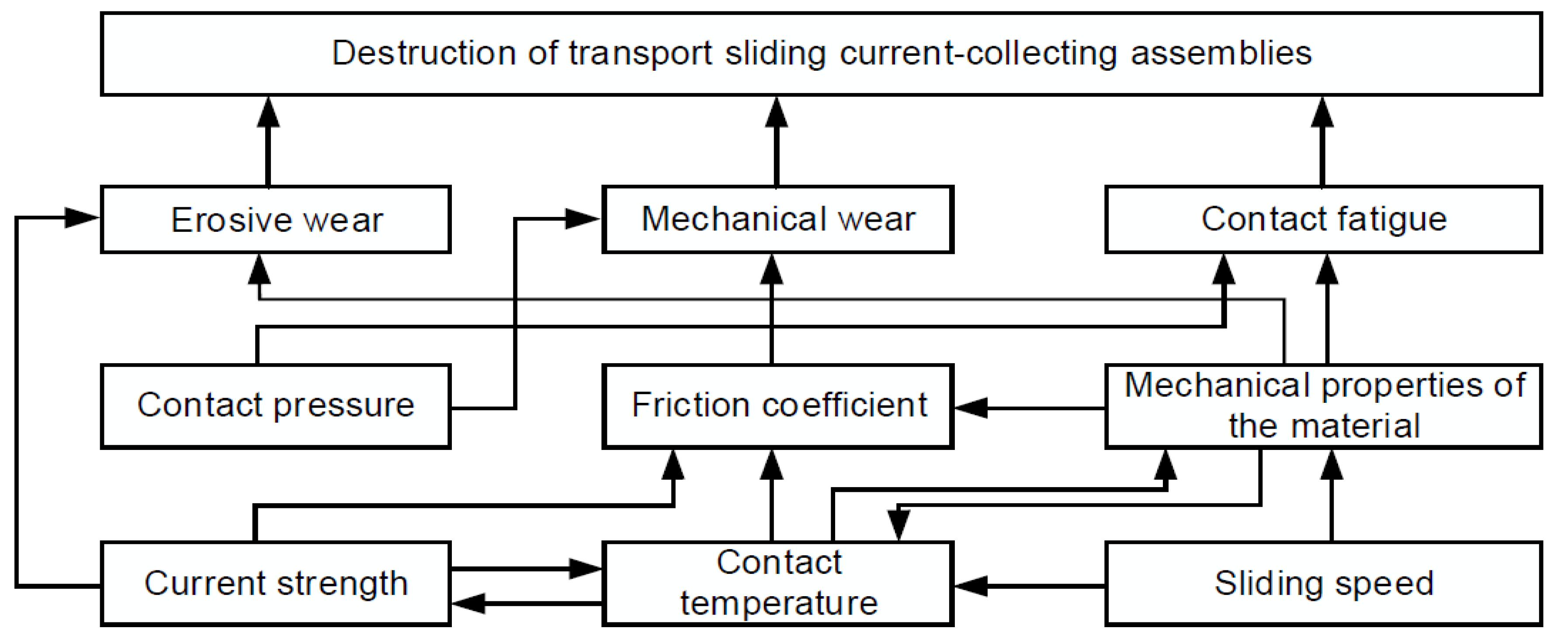
Figure 2.
Co-occurrence map of keywords from the publications included in this review (minimum frequency: 3 keywords), generated using VOSviewer 1.6.20 software.
Figure 2.
Co-occurrence map of keywords from the publications included in this review (minimum frequency: 3 keywords), generated using VOSviewer 1.6.20 software.
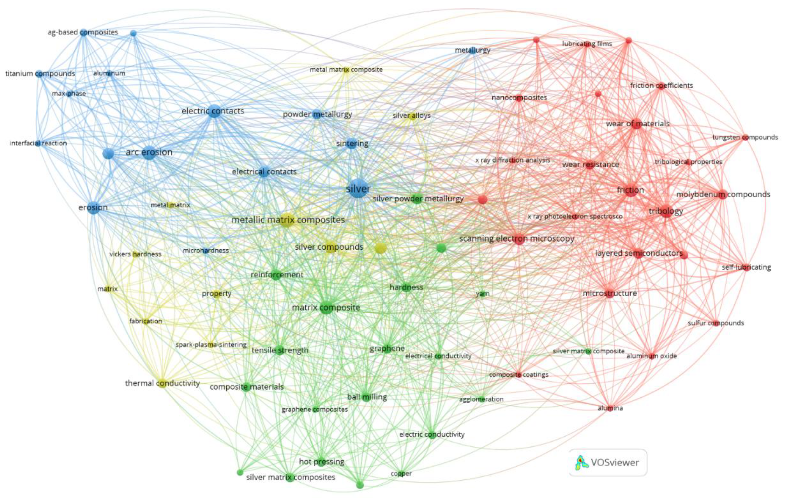
Figure 3.
Nanoscale interfacial and surface friction mechanisms of 2D layered materials, involving Prandtl-Tomlinson [49,50] and Frenkel-Kontorova [50,51] models. Reprinted from Liu et al. [47], Copyright: © 2019, The authors. This article is openly licensed via Creative Commons CC-BY-4.0 (https://creativecommons.org/licenses/by/4.0/).
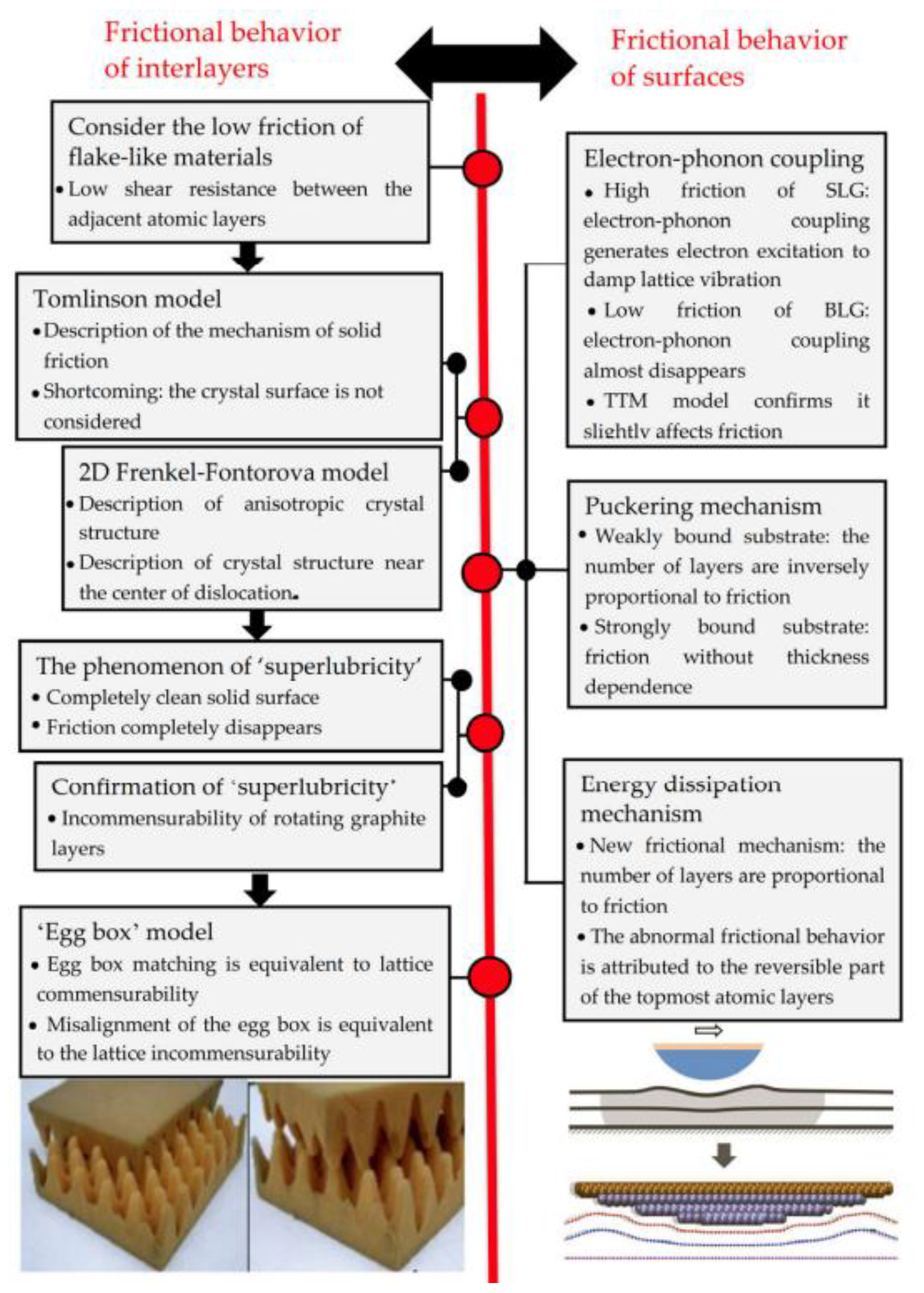
Figure 4.
Schematic flow chart for the preparation of sintered Ag-Cu-Ni-WS2-MoS2 composites via PM. Reprinted from Zhu et al. [14], Copyright: © 2025, The authors. This article is openly licensed via Creative Commons CC-BY-NC-ND-4.0 (https://creativecommons.org/licenses/by-nc-nd/4.0/).
Figure 4.
Schematic flow chart for the preparation of sintered Ag-Cu-Ni-WS2-MoS2 composites via PM. Reprinted from Zhu et al. [14], Copyright: © 2025, The authors. This article is openly licensed via Creative Commons CC-BY-NC-ND-4.0 (https://creativecommons.org/licenses/by-nc-nd/4.0/).
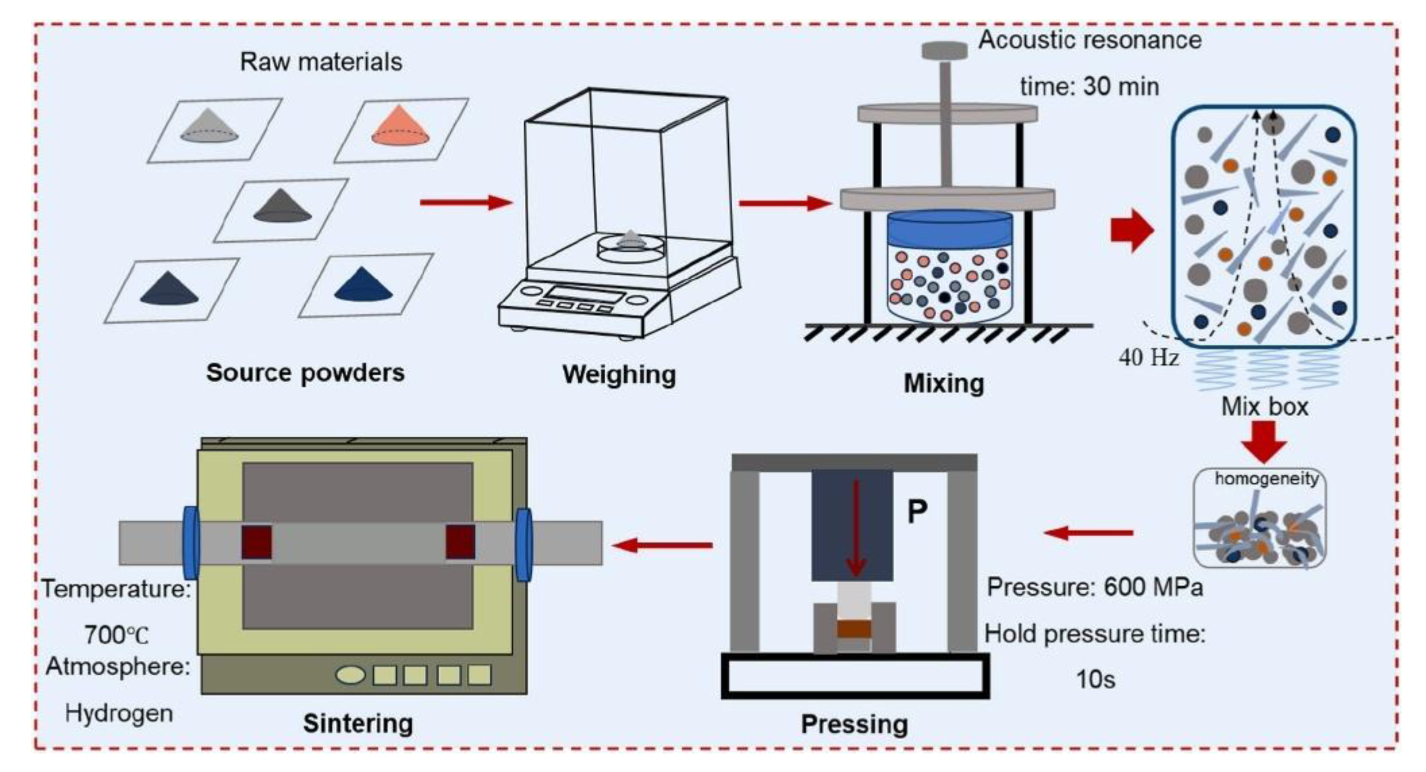
Figure 5.
Schematic diagram of (a) the surface friction treatment (SFT) of sintered Ag-Cu-Ni-WS2-MoS2 composites, and (b) treatment conditions. Reprinted from Zhu et al. [14], Copyright: © 2025, The authors. This article is openly licensed via Creative Commons CC-BY-NC-ND-4.0 (https://creativecommons.org/licenses/by-nc-nd/4.0/).
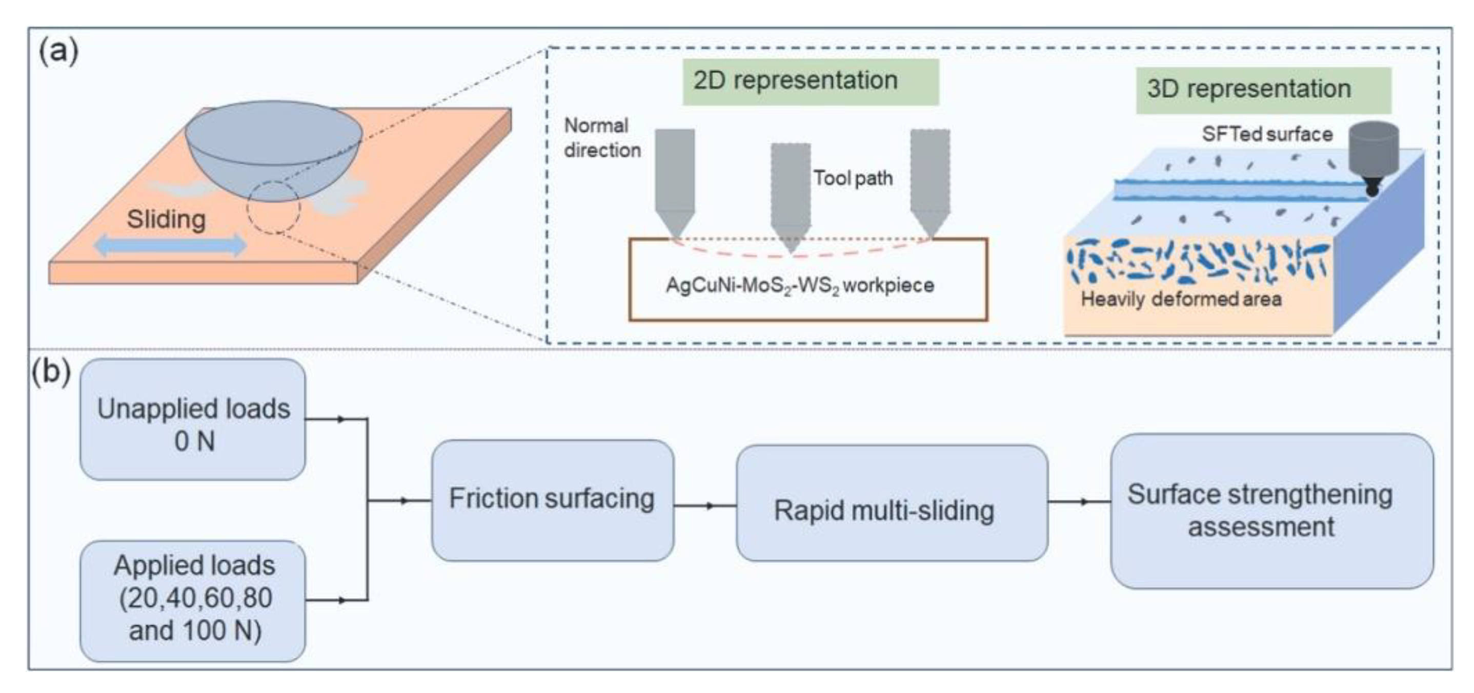
Figure 6.
Schematic preparation flow chart for sintered Ag@CNTs/Ag composites via SPS and HPS. Reprinted from Jia et al. [43], Copyright: © 2019, The authors. This article is openly licensed via Creative Commons CC-BY-NC-ND-4.0 (https://creativecommons.org/licenses/by-nc-nd/4.0/).
Figure 6.
Schematic preparation flow chart for sintered Ag@CNTs/Ag composites via SPS and HPS. Reprinted from Jia et al. [43], Copyright: © 2019, The authors. This article is openly licensed via Creative Commons CC-BY-NC-ND-4.0 (https://creativecommons.org/licenses/by-nc-nd/4.0/).
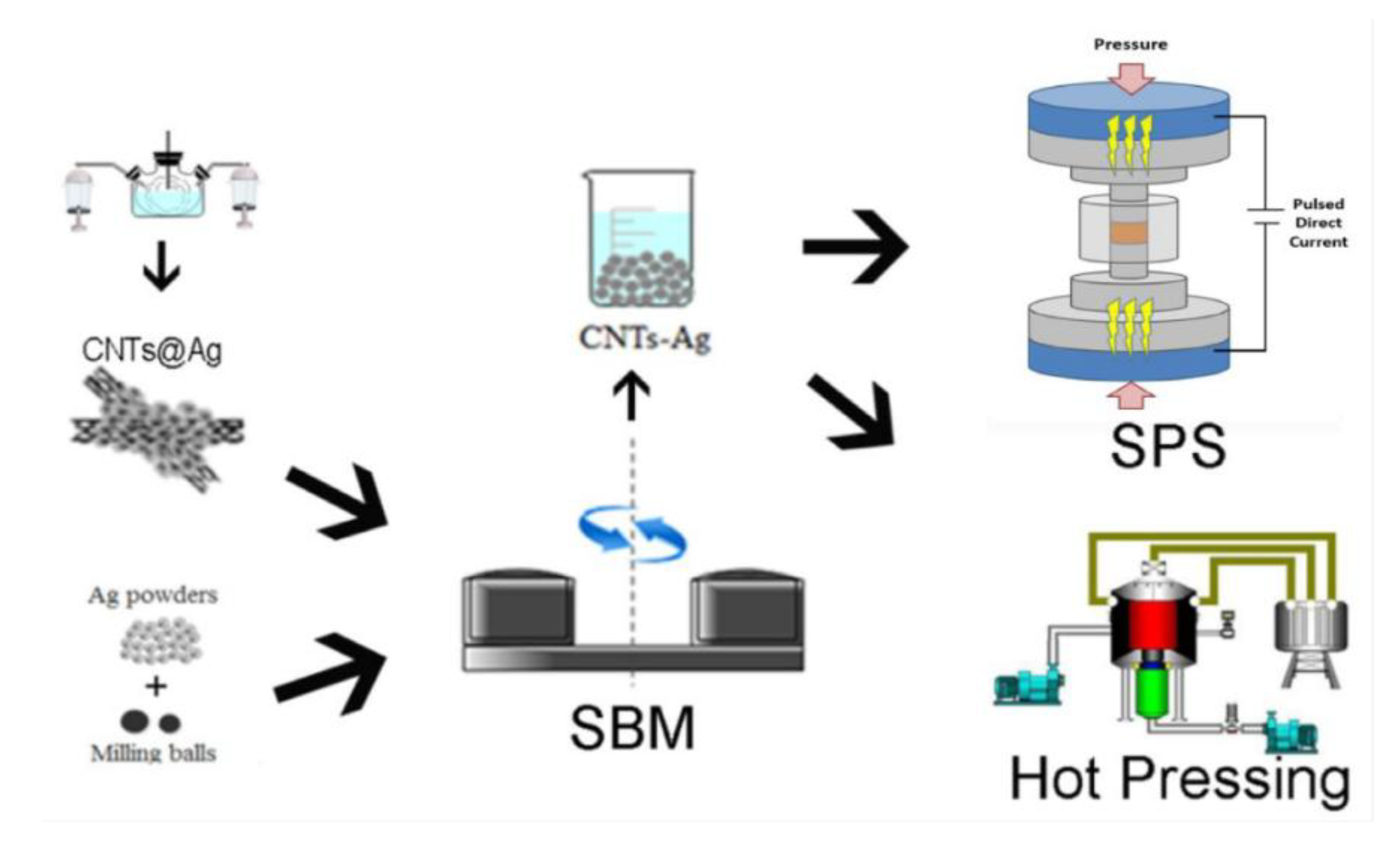
Figure 7.
Schematic illustration of the evolution of the lubricating film on the worn surface of a self-lubricating MMC during sliding against a counterbody disc. Reprinted from Xiao et al. [69], Copyright: © 2019, The authors. This article is openly licensed via Creative Commons CC-BY-NC-ND-4.0 (https://creativecommons.org/licenses/by-nc-nd/4.0/).
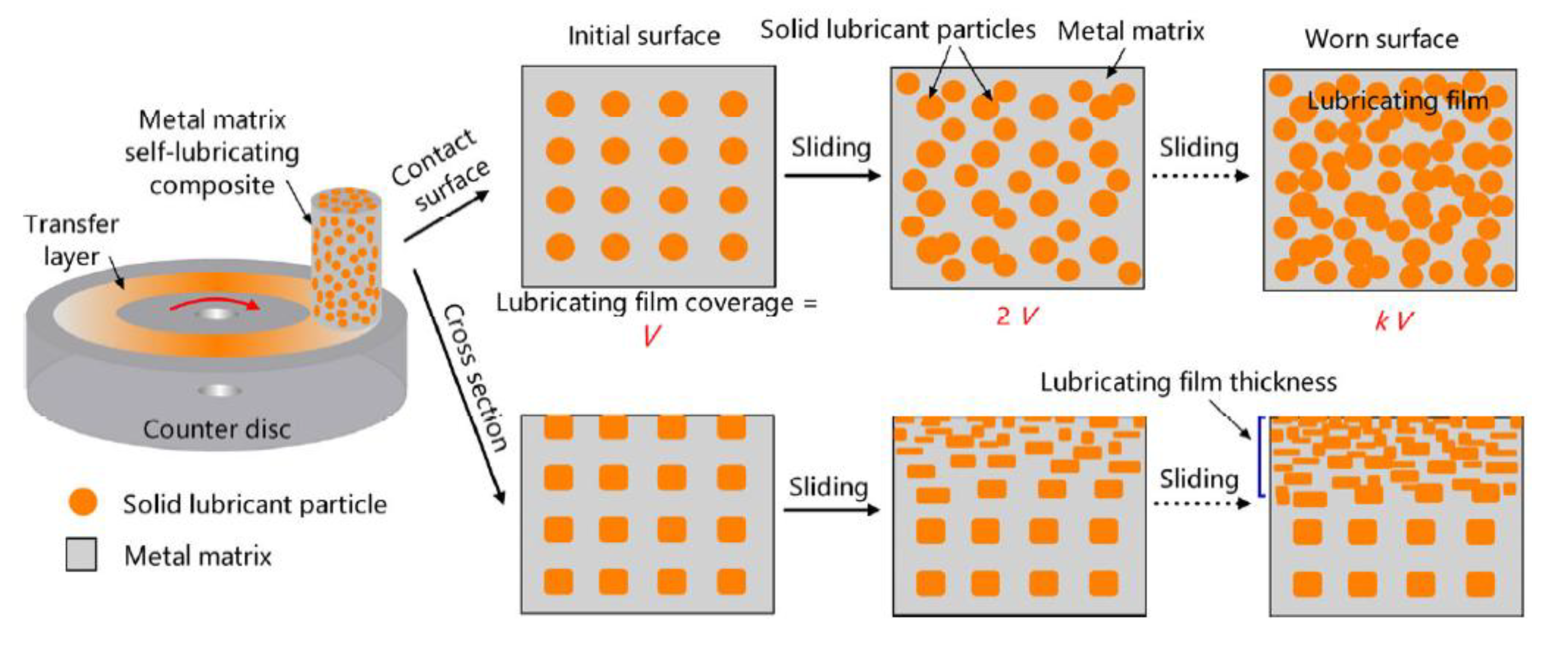
Figure 8.
Schematic illustration of the three contact types in self-lubricating MMCs: (a) metal-metal, (b) metal-film, and (c) film-film, along with their respective contact rates and corresponding COFs. Reprinted from Xiao et al. [69], Copyright: © 2019, The authors. This article is openly licensed via Creative Commons CC-BY-NC-ND-4.0 (https://creativecommons.org/licenses/by-nc-nd/4.0/).
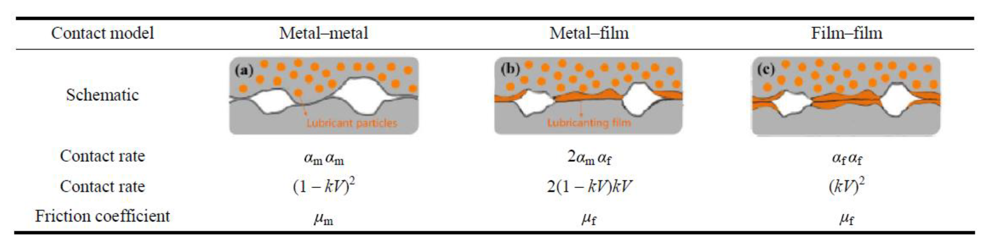
Figure 9.
Schematic illustration of the evolution of the lubricating film on the worn surface of a self-lubricating MMC during Ar+ etching: (a) cross section of the worn surface, (b) worn surface morphology, and (c) corresponding XPS analysis results. Reprinted from Xiao et al. [69], Copyright: © 2019, The authors. This article is openly licensed via Creative Commons CC-BY-NC-ND-4.0 (https://creativecommons.org/licenses/by-nc-nd/4.0/).
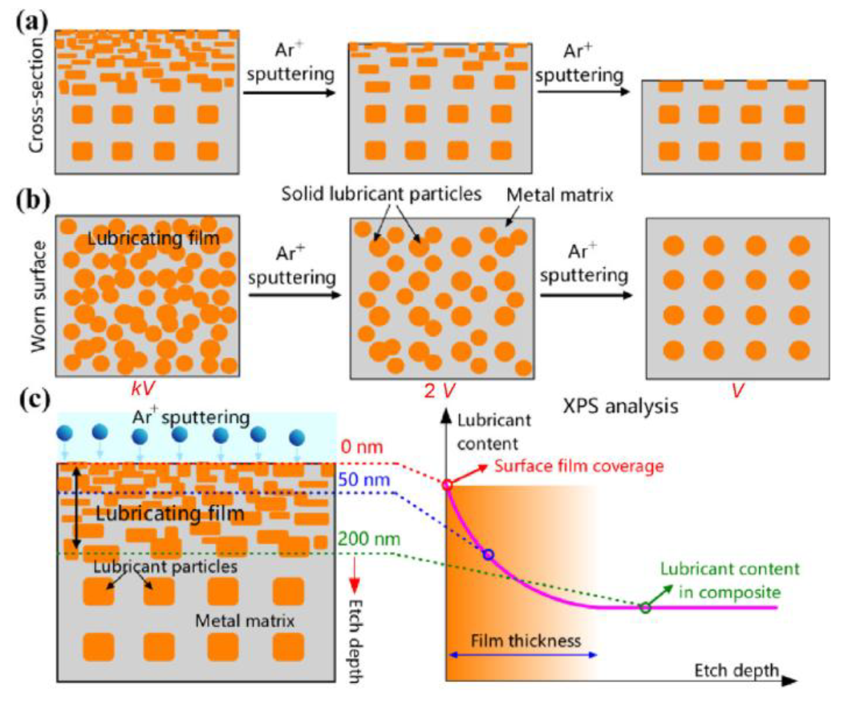
Figure 10.
Backscattered electron (BSE) images showing (a) the microstructure and (b-e) the Energy Dispersive Spectroscopy (EDS) elemental maps of the sintered Ag-WS2-MoS2 NCs. Reprinted from Khan et al. [6], Copyright: © 2020, The authors. This article is openly licensed via Creative Commons CC-BY-4.0 (https://creativecommons.org/licenses/by/4.0/).
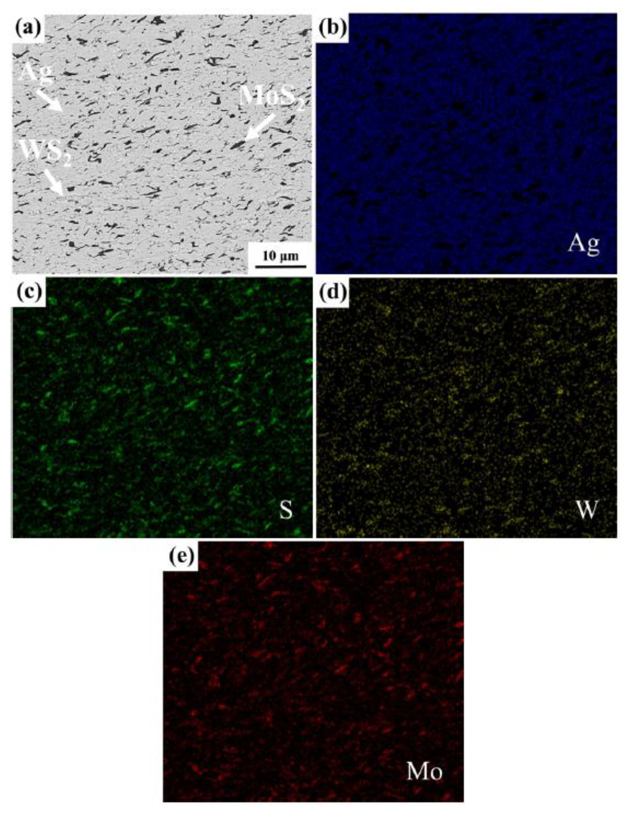
Figure 11.
Variation of COF and lubricating film thickness versus sliding distance of Ag-WS2-MoS2 NCs for the sliding speed of (a) 0.01 m/s, (b) 0.1 m/s, and (c) 1 m/s, and (d) influence of the sliding speed on variation of lubricating film thickness versus sliding distance. Reprinted from Khan et al. [6], Copyright: © 2020, The authors. This article is openly licensed via Creative Commons CC-BY-4.0 (https://creativecommons.org/licenses/by/4.0/).
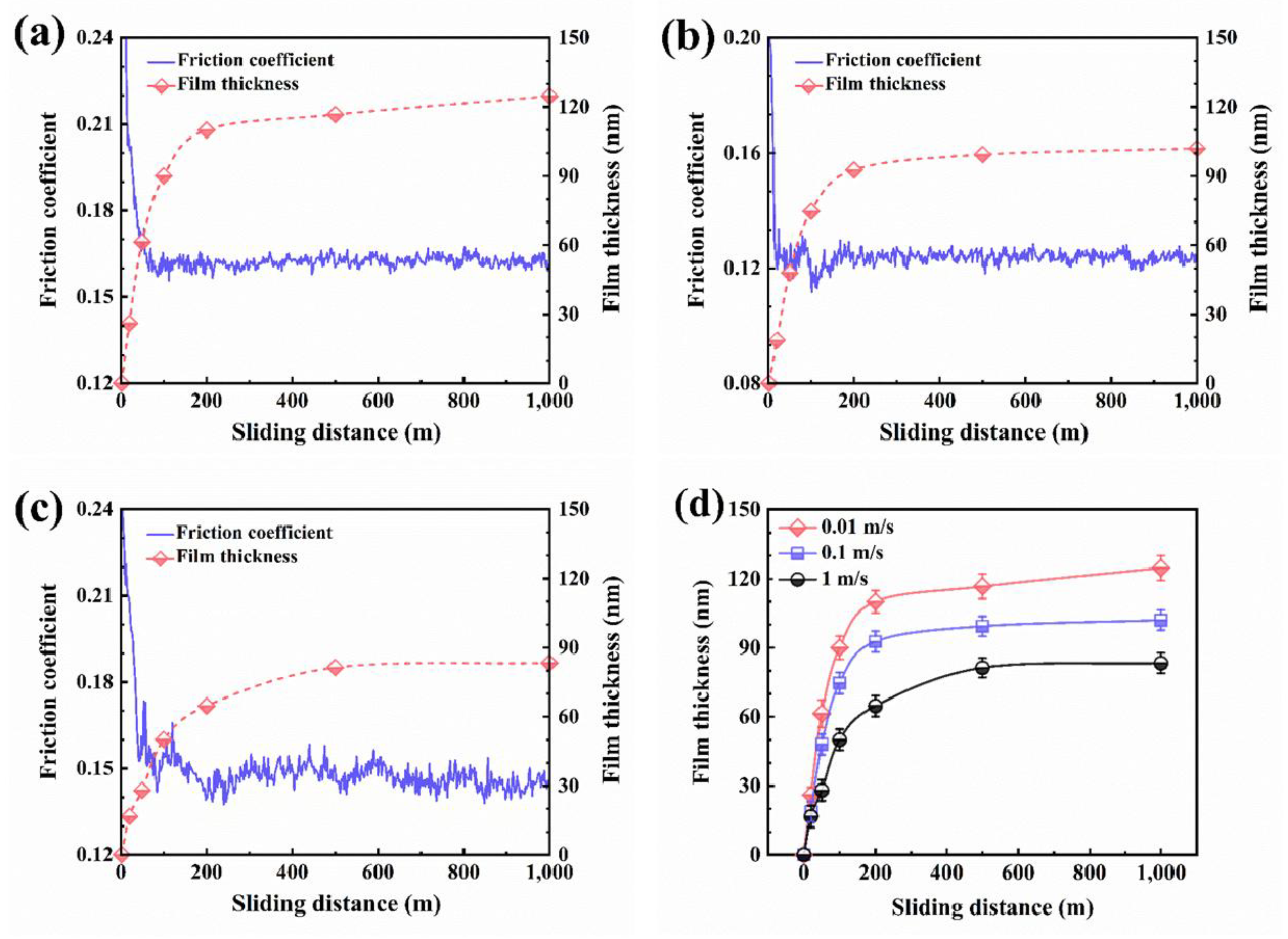
Figure 12.
Variation of the atomic percentages of Ag, W, and Mo in the transfer films with sliding distance. Reprinted from Khan et al. [6], Copyright: © 2020, The authors. This article is openly licensed via Creative Commons CC-BY-4.0 (https://creativecommons.org/licenses/by/4.0/).
Figure 12.
Variation of the atomic percentages of Ag, W, and Mo in the transfer films with sliding distance. Reprinted from Khan et al. [6], Copyright: © 2020, The authors. This article is openly licensed via Creative Commons CC-BY-4.0 (https://creativecommons.org/licenses/by/4.0/).
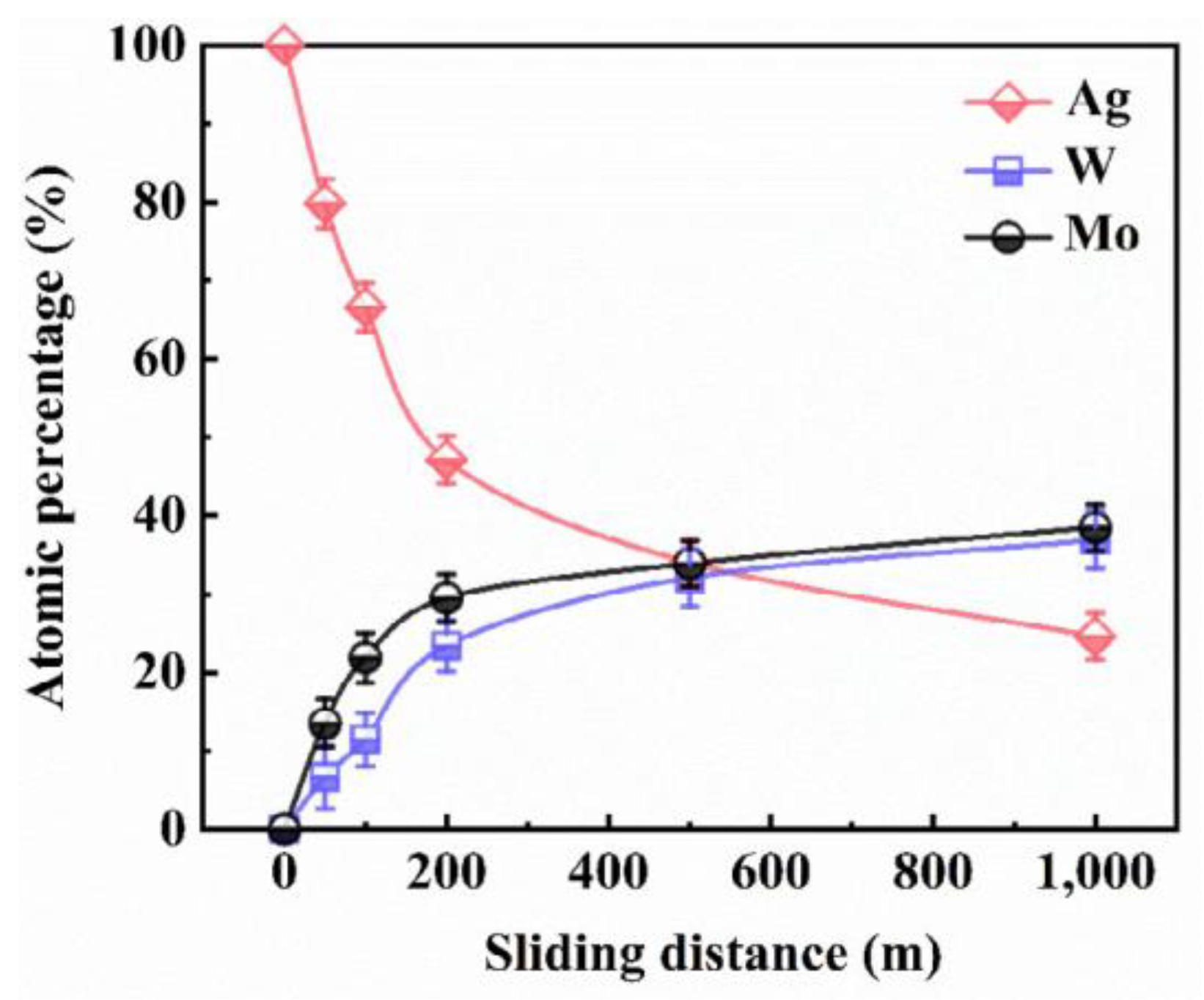
Figure 13.
Schematic illustration of (a) the coupled thermal, mechanical, electrical, and magnetic mechanisms of CCFW, and (b) the key factors affecting CCFW. Reprinted from Sui et al. [70], Copyright: © 2025, The authors. This article is openly licensed via Creative Commons CC-BY-4.0 (https://creativecommons.org/licenses/by/4.0/).
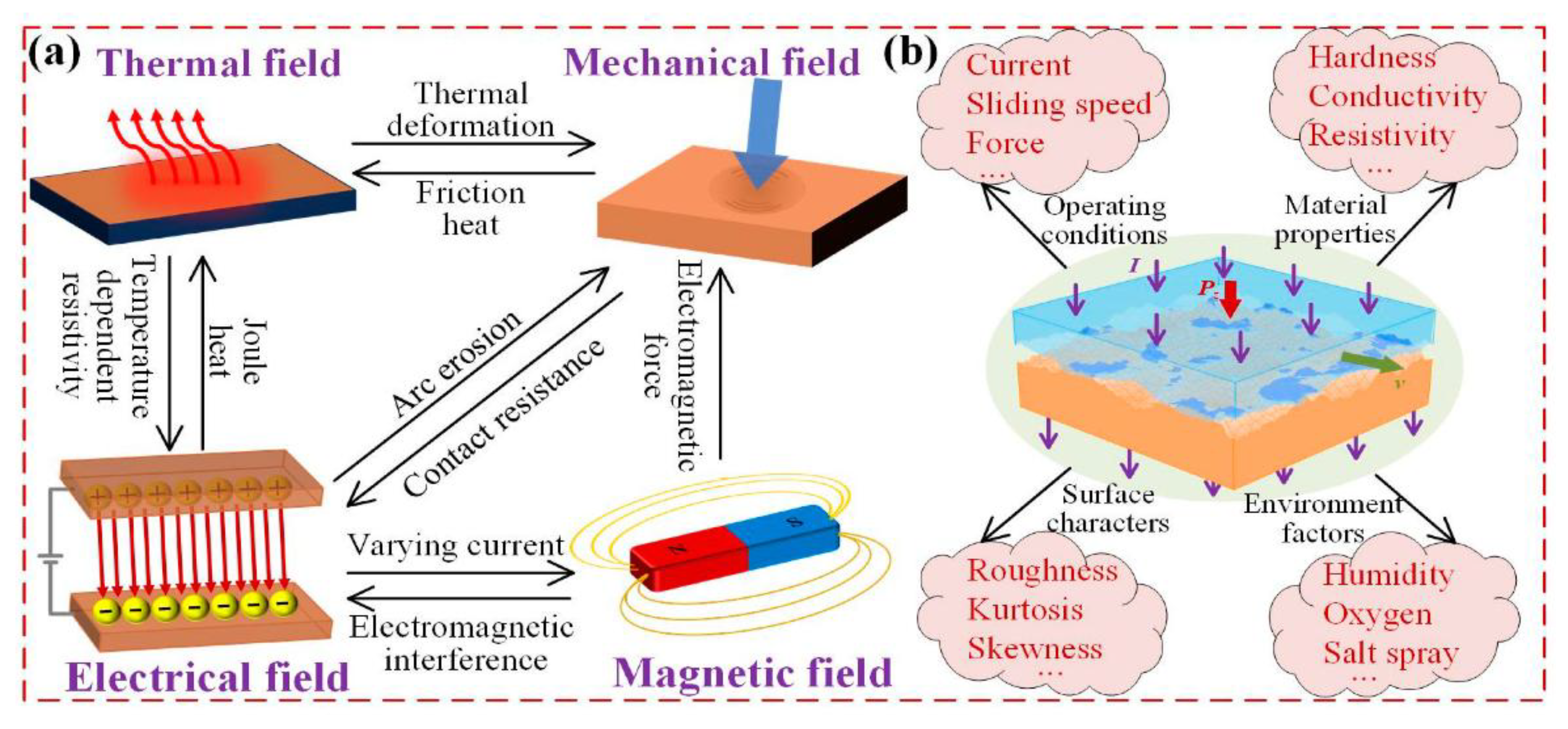
Figure 14.
Schematic illustration of the key factors affecting CCFW and the approach to develop new materials. Reprinted from Li et al. [71], Copyright: © 2022, The authors. This article is openly licensed via Creative Commons CC-BY-4.0 (https://creativecommons.org/licenses/by/4.0/).
Figure 14.
Schematic illustration of the key factors affecting CCFW and the approach to develop new materials. Reprinted from Li et al. [71], Copyright: © 2022, The authors. This article is openly licensed via Creative Commons CC-BY-4.0 (https://creativecommons.org/licenses/by/4.0/).
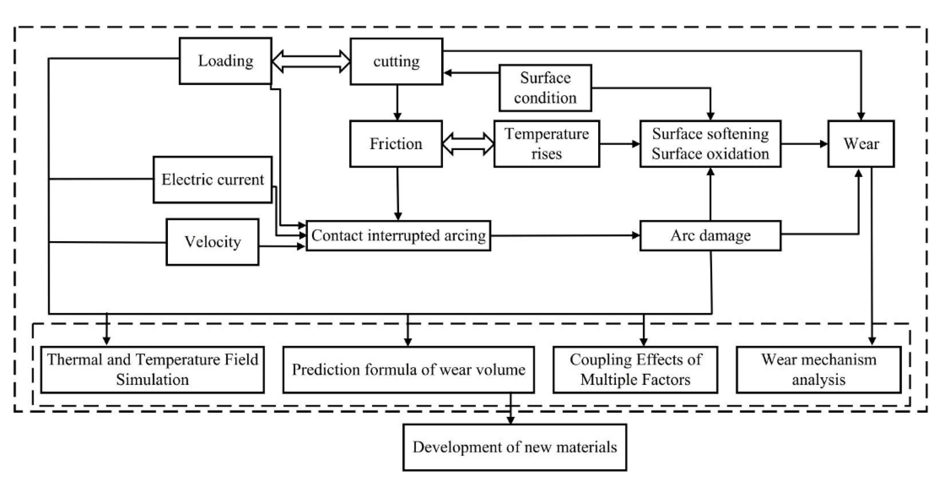
Figure 15.
Flowchart of setting up of a sliding electrical contact simulation model of a pantograph-catenary system. Reprinted from Fengyi et al. [73], Copyright: © 2020, The authors. This article is openly licensed via Creative Commons CC-BY-4.0 (https://creativecommons.org/licenses/by/4.0/).
Figure 15.
Flowchart of setting up of a sliding electrical contact simulation model of a pantograph-catenary system. Reprinted from Fengyi et al. [73], Copyright: © 2020, The authors. This article is openly licensed via Creative Commons CC-BY-4.0 (https://creativecommons.org/licenses/by/4.0/).
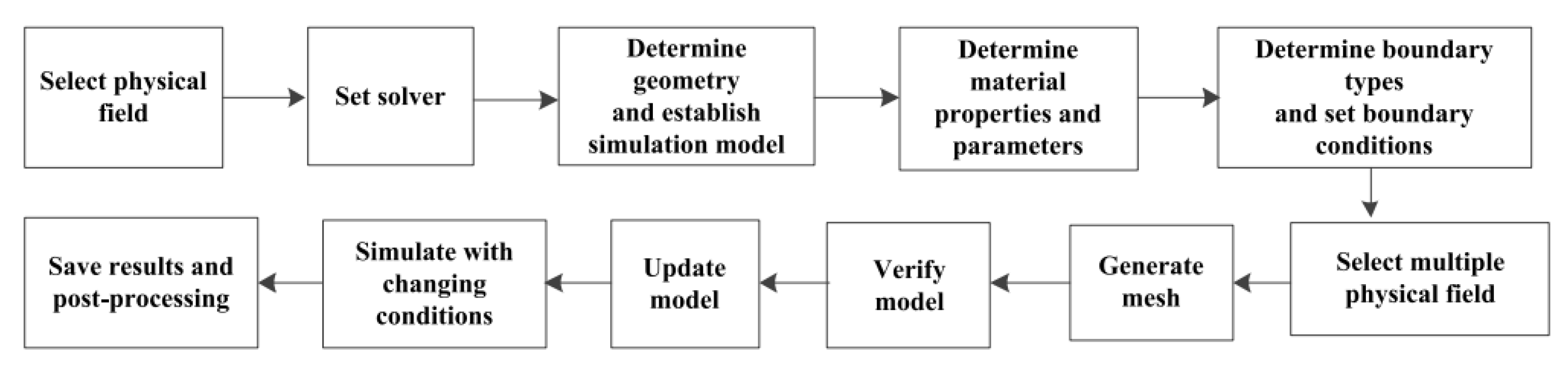
Figure 16.
Schematic overview of the main research gaps and emerging directions for self-lubricating AgMNC electrical contacts.
Figure 16.
Schematic overview of the main research gaps and emerging directions for self-lubricating AgMNC electrical contacts.
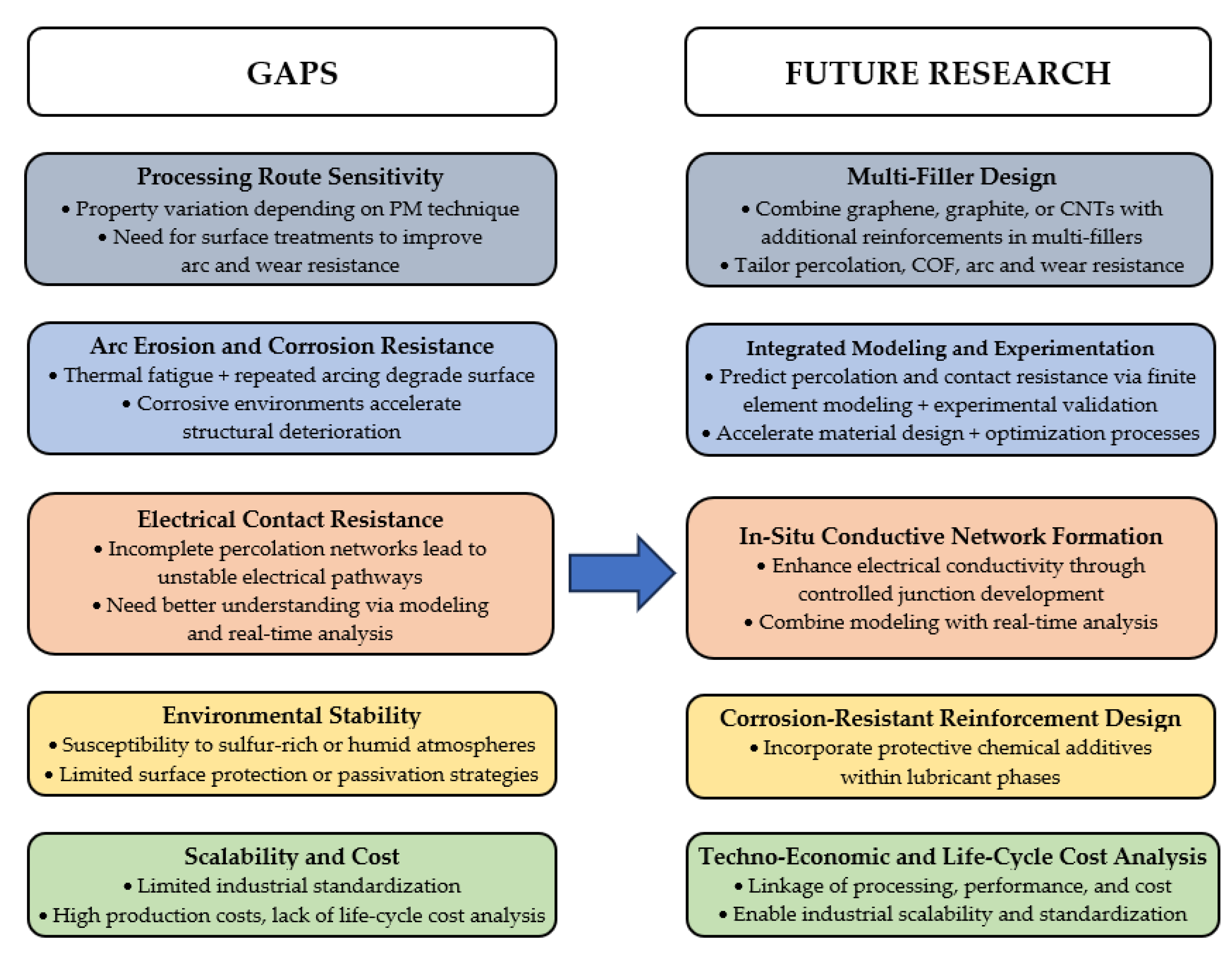

Table 1.
Common solid lubricants used in AgMCs and AgMNCs and their key benefits.
| Solid Lubricants |
Main Properties of Solid Lubricants | Key Benefits in AgMCs and AgMNCs |
References |
|---|---|---|---|
| Molybdenum disulfide (MoS2) |
- 2D layered TMD structure, - Good lubricity in vacuum and dry air, - Moderate oxidation resistance, - Stable up to 350°C, COF of 0.05−0.25 in dry tribo-contacts. |
- Forms stable tribofilm, - Reduces friction and wear, - Improves load capacity. |
[6,15,16,27,29,41] |
| Tungsten disulfide (WS2) |
- 2D layered TMD structure; - Higher oxidation and thermal stability than MoS₂; - Lower COF than MoS₂ under high load; - Stable up to 425°C, COF of 0.05−0.25 in dry tribo-contacts. |
- Enhances tribological performance at high temperature (HT), - Improves durability in oxidative environments. |
[4,17,18,27,29] |
| MoS₂ + WS₂ | - Synergistic 2D layered lubricants with improved vacuum and dry air performance versus single phases (MoS2 or WS2) |
- Enhances self-lubricating performance of composites under vacuum. |
[29,44] |
| Graphite | - 2D layered carbon structure, - Excellent lubricity in humid/HT environments, - Cost-effective, lightweight, good electrical conductivity; - Stable up to 500°C, COF of 0.1−0.3 in dry tribo-contacts. |
- Lowers friction in ambient air, - Improves wear resistance, - Higher graphite contents reduce conductivity and strength. |
[6,19,26,27,28] |
| Carbon nanotubes (CNTs) |
- Tubular carbon nanostructures (SWCNTs or MWCNTs), - High aspect ratio (length to diameter (L/D) ratio), - Thermal stability depends on CNT size (shorter/larger diameter CNTs are more resistant to thermal loads), - Lightweight (bulk density of CNTs of ~1.3−2.1 g/cm3), - Excellent mechanical and electrical properties. |
- Enhance hardness and wear resistance, and maintain conductivity of composites if CNTs are well-dispersed in Ag matrix, and/or surface functionalized; - Promotes tribofilm formation. |
[2,20,28,42,43,45,46] |
| Graphene / Graphene Oxide (GO) / Reduced GO (rGO) |
- Monolayer/multilayer 2D carbon sheet structure, - Remarkable mechanical strength, - High electrical and thermal conductivity, - High aspect ratio (lateral dimension to sheet thickness ratio). |
- Strengthen Ag matrix, - Reduces friction and wear, - Conductivity/strength depend on graphene/GO/rGO contents. |
[24,25,26] |
Table 2.
Comparison of conventional and advanced PM techniques for sintered AgMNCs.
| Features | Conventional Powder Metallurgy (PM) | Hot Pressing Sintering (HPS) |
Spark Plasma Sintering (SPS) |
|---|---|---|---|
| Compaction method | Cold pressing at RT | Heat and uniaxial pressure applied simultaneously during sintering |
Uniaxial pressure combined with high-intensity, low-voltage pulsed (on-off) electric current |
| Sintering process | Furnace-heating without external pressure during densification | Pressure-assisted furnace sintering |
Field-assisted rapid sintering with pressure and pulsed (on-off) electric current |
| Sintering temperature (Ts) |
High Ts (typical 700–850°C) |
Lower Ts than in conventional PM |
Significantly lower Ts than in conventional PM by more than 200°C due to rapid Joule heating |
| Dwell time (DT) at Ts | Long (hours) | Long (hours) | Very short (minutes) |
| Heating rate (HR) | Slow (typical 5–10°C/min) |
Slow (typical 10–50°C/min) |
Very fast (typical 50–300°C/min, depending on SPS equipment and sample size) |
| Cooling rate (CR) | Slow (typical 1–10°C/min) | Slow (typical 10–50°C/min) | Very fast (typical ≤ 150°C/min) |
| Densification mechanisms |
Solid-state diffusion, Neck growth of powder particles, Shrinkage of compacts |
Pressure assisted plastic deformation, Volume diffusion |
Pressure-assisted deformation, enhanced diffusion, Joule heating effect, and localized vaporization/plasma surface cleaning |
| Grain size | Larger grains, more grain growth than in HPS/SPS | Finer grains than in conventional PM |
Nanostructure retention with minimal grain growth |
| Relative density (RD) and porosity of sintered AgMNCs |
Lower RD (often < 95% of TD), higher porosity than in HPS and SPS |
Higher RD, lower porosity than in conventional PM |
Very high RD (often 99% of TD), lowest porosity |
| Distribution/bonding of solid lubricants into Ag matrix | Higher risk of agglomeration, often weak bonding | Better dispersion, improved bonding |
Best dispersion and strong bonding |
| Mechanical/tribological properties of sintered AgMNCs | Good properties | Improved properties | High-performance SECs with superior properties |
| Processing cost | Cost-effective | Moderate cost | High cost (specialized SPS equipment, graphite/WC dies) |
| Scalability | High scalability | Moderate scalability | Reduced scalability (restricted by die size and equipment cost) |
Table 3.
Summary of compositions, PM processing route and key parameters for obtaining sintered AgMNCs, along with several AgMNC pin and counterbody (CB) disc characteristics, tribological test conditions, and the corresponding COF and wear rate of the tested pins.
Table 3.
Summary of compositions, PM processing route and key parameters for obtaining sintered AgMNCs, along with several AgMNC pin and counterbody (CB) disc characteristics, tribological test conditions, and the corresponding COF and wear rate of the tested pins.
| AgMNC Composition |
PM Route and Key Parameters (Pp, Ts, DT) |
AgMNC Pin Dimensions, Relative Density, hardness |
CB Disc Material, Diameter, Hardness |
Tribological Test Conditions |
Average Coefficient of Friction of AgMNCs |
Average Wear Rate of AgMNC Pins (mm3/N·m) |
Reference | ||
|---|---|---|---|---|---|---|---|---|---|
|
Fn (N) |
vs (m/s) |
d (m) |
|||||||
| Ag-10 wt.%WS2- 5 wt.%MoS2 |
HPS in N2 gas: 25 MPa, 750°C, DT: NR |
3 × 3 × 3 mm3, 99%, 73.4 HB |
Ag-10%Cu, Ø50 mm, 120.3 HB |
1 | 0.01 | 1000 | 0.16 | 2.17×10⁻6 | [6] |
| 1 | 0.1 | 1000 | 0.12 | 2.82×10⁻6 | |||||
| 1 | 1.0 | 1000 | 0.14 | 8.17×10⁻6 | |||||
| Ag-10 wt.%WS2- 5 wt.%MoS2 NC |
SPS, vacuum: 50 MPa, 750°C, 5 min |
3 × 3 × 3 mm3, 98.9%, 71.6 HB | Ag-10%Cu, Ø: NR, 120 HB |
1 | 0.01–1.0 | 10000 | 0.126–0.158 | (1.37–6.17)×10⁻6 | [60] |
| Ag-10 wt.%WS2- 5 wt.%MoS2 MC |
3 × 3 × 3 mm3, 97.9%, 52.1 HB | 1 | 0.01–1.0 | 10000 | 0.158–0.178 | (35.28–92.97)×10⁻6 | |||
| Ag-WS2-MoS2 (composition: NR) |
HPS in N2 gas: 24 MPa, 780°C, DT: NR |
Ø12 mm × 1.5 mm, 98%, 63.9 HV0.5 |
Ag-Cu, Ø50 mm, Alloy composition + HB: NR |
0.25 | 0.1–1.0 | 5000 | 0.31–0.65 | (2.67–19.80)×10⁻5 | [57] |
| 0.5 | 0.1–1.0 | 5000 | 0.27–0.38 | (4.30–13.51)×10⁻5 | |||||
| 1 | 0.1–1.0 | 5000 | 0.20–0.27 | (3.05–8.38)×10⁻5 | |||||
| 2 | 0.1–1.0 | 5000 | 0.14–0.25 | (5.45–11.49)×10⁻5 | |||||
| 4 | 0.1–1.0 | 5000 | 0.09–0.14 | (3.03–18.48)×10⁻5 | |||||
| Ag-10 wt.%WS2- 10 wt.%MoS2 NC |
SPS, atm. NR: 40 MPa, ~800°C, 10 min |
3 × 3 × 3 mm3, 98.8%, 70.7 HB | Ag-10%Cu, Ø: NR, 119.7 HB |
1 | 0.1–1.0 | 10000 | 0.125–0.139 | (2.53–7.49)×10⁻6 | [29] |
| Ag-10 wt.%WS2- 10 wt.%MoS2 MC |
3 × 3 × 3 mm3, 97.6%, 51.3 HB | 1 | 0.1–1.0 | 10000 | 0.155–0.171 | (12.39–35.81)×10⁻6 | |||
| Ag-30 vol.%WS2 | SPS: atm. NR: 35 MPa, 750°C, 10 min | POD testing conditions: NR Pin size, relative density and hardness: NR |
Parallel-plane | 0.16 | 3.08×10⁻5 | [18] | |||
| Perpendicular-plane | 0.24 | 8.23×10⁻5 | |||||||
| Ag-5 vol.% SG | SPS, vacuum: 40 MPa, 750°C, 10 min |
3 × 4 × 4 mm3, 98.2%, 78.9 HV1 | Ag-10%Cu, Ø: NR, 120 HV1 |
3 | 0.5 | 20000 | 0.44 | 6.7×10⁻5 | [68] |
| Ag-35 vol.% SG | 3 × 4 × 4 mm3, 97.4%, 46.3 HV1 | 3 | 0.5 | 20000 | 0.16 | 0.16×10⁻5 | |||
| Ag-5 vol.% FG | SPS, vacuum: 40 MPa, 750°C, 10 min |
3 × 4 × 4 mm3, 97.4%, 68.3 HV1 | Ag-10%Cu, Ø: NR, 120 HV1 |
3 | 0.5 | 20000 | 0.42 | 25×10⁻5 | [68] |
| Ag-35 vol.% FG | 3 × 4 × 4 mm3, 95.1%, 38.5 HV1 | 3 | 0.5 | 20000 | 0.21 | 6.5×10⁻5 | |||
Table 4.
Wear mechanisms identified for Ag-WS2-MoS2 NCs under different sliding speeds and normal forces (adapted from Zhang et al. [57]).
Table 4.
Wear mechanisms identified for Ag-WS2-MoS2 NCs under different sliding speeds and normal forces (adapted from Zhang et al. [57]).
| Sliding Speed |
Applied Normal Force | ||||
|---|---|---|---|---|---|
| 0.25 N | 0.5 N | 1 N | 2 N | 4 N | |
| Wear Mechanisms | |||||
| 0.1 m/s | Adhesion | Adhesion | Ploughing | Ploughing | Ploughing |
| 0.2 m/s | Ploughing | Adhesion | Adhesion | Ploughing | Adhesion |
| 0.4 m/s | Ploughing | Ploughing | Ploughing | Adhesion | Adhesion |
| 0.6 m/s | Ploughing | Ploughing | Ploughing | Adhesion | Adhesion |
| 0.8 m/s | Adhesion | Adhesion | Adhesion | Oxidation delamination | Oxidation delamination |
| 1.0 m/s | Adhesion | Adhesion | Adhesion | Oxidation delamination | Oxidation delamination |
Disclaimer/Publisher’s Note: The statements, opinions and data contained in all publications are solely those of the individual author(s) and contributor(s) and not of MDPI and/or the editor(s). MDPI and/or the editor(s) disclaim responsibility for any injury to people or property resulting from any ideas, methods, instructions or products referred to in the content. |
© 2025 by the authors. Licensee MDPI, Basel, Switzerland. This article is an open access article distributed under the terms and conditions of the Creative Commons Attribution (CC BY) license (https://creativecommons.org/licenses/by/4.0/).
Copyright: This open access article is published under a Creative Commons CC BY 4.0 license, which permit the free download, distribution, and reuse, provided that the author and preprint are cited in any reuse.


