
Submitted:
10 December 2025
Posted:
12 December 2025
You are already at the latest version
Abstract
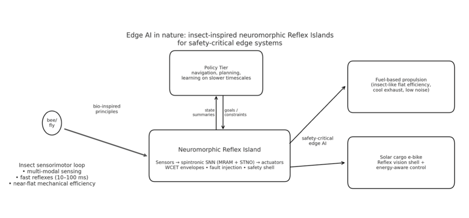
Insects achieve millisecond sensor–motor loops with tiny sensors, compact neural circuits, and powerful actuators, embodying the principles of Edge AI long before electronics existed [1–9]. In this perspective, we treat insects as canonical edge-AI systems and translate their neurobiology and physiology into a concrete engineering stack: a latency-first control hierarchy that partitions tasks between a fast, dedicated Reflex Tier and a slower, robust Policy Tier, with explicit WCET envelopes and freedom-from-interference boundaries [1–9]. This architecture is realized through a neuromorphic Reflex Island built from spintronic and neuromorphic primitives, MRAM synapses for non-volatile, innate reflex memory, and spin-torque nano-oscillator (STNO) reservoirs for temporal processing—yielding instant-on, memory-centric reflexes compatible with emerging industrial roadmaps [10–16,56,62–67].We further formalize the thermoregulatory and respiratory strategies that allow insects to maintain nearly constant mechanical efficiency across a wide load range: active thoracic temperature control and Discontinuous Gas Exchange (DGC) [17–33]. These mechanisms motivate firmware-level “thermal-debt” and burst-budget controllers, contrasting sharply with the narrow best-efficiency islands of internal combustion engines and miniturbines [34–43]. We instantiate this integrated bio-inspired model in two concrete edge systems: an insect-like IFEVS thruster with nearly flat-band thermal efficiency over thrust, and a solar-assisted cargo e-bike equipped with an insect-inspired neuromorphic safety shell [6,11,14,28,58–61]. Across these examples we provide efficiency comparisons, latency and energy budgets, and safety-case hooks (fault taxonomies, WCET envelopes) aimed at guiding adoption in safety-critical domains.
Keywords:
Edge AI
; insect inspired control
; optic flow
; halteres
; discontinuous gas exchange
; thermoregulation
; neuromorphic computing
; spintronics
; MRAM
; STNO
; WCET
Glossary Table
- Reflex Tier — fastest safety-critical control with hard deadlines (Control).
- Reflex Island — isolated near-sensor partition executing the Reflex Tier (Platform).
- Reflex substrate (spintronic/CMOS) — technology implementing the Reflex Tier (Platform).
- Policy Tier — slower mapping/planning; publishes goals to Reflex (Control)
- FFI (freedom-from-interference) — faults/jitter in Policy can’t affect Reflex (Safety).
- ASIL allocation — ISO 26262 safety level assignment per function (Safety).
- DGC (Discontinuous Gas Exchange) — Closed–Flutter–Open; analogy for idle I/O gating (Biology↔Firmware).
- Thermal debt — required cool-down after a burst (Thermal).
- Set-point temperature — maintained flight-muscle band during work (Thermal/Biology).
- Cooling conductance G — linearized convection + radiation loss (Physics).
- Thermal time constant τ — response time; scales roughly with size (Physics).
- Prime mover — fuel engine/turbine kept at efficiency island (Propulsion).
- Cold-to-idle latency — light-off to usable idle time (Propulsion).
- BSFC map — brake-specific fuel consumption vs rpm/load (Efficiency).
- Injection event (micro-injection) — one pulse in a split injection (Engines).
- Thoracic shivering — pre-flight warm-up of flight muscles (Biology/Thermal).
- Optic flow — wide-field visual motion cue (Sensing).
- Halteres — gyroscopic sensory organs in Diptera (Sensing).
- Dorsal Rim Area (DRA) — polarization-sensitive zone for celestial compass (Sensing).
- Central Complex (ring attractor) — neural compass with an activity bump (Control/Biology).
- CPG (central pattern generator) — rhythmic actuation circuit (Control/Biology).
- STNO reservoir — spin-torque oscillator network for temporal processing (Hardware).
- MRAM synapse — non-volatile weight (MTJ) for instant-on reflex (Hardware).
- DVFS — dynamic voltage/frequency scaling under thermal control (Platform).
- WCET envelope — worst-case execution-time budget from sensor exposure to actuator update, including safety margin, defined per Reflex loop (Timing/Safety).
1. Introduction: Insects as Canonical Edge-AI Systems
Insects execute navigation, stabilization, landing, foraging, and escape entirely on-device, using parallel sensors (compound eyes, ocelli, halteres, antennae) connected by short neural pathways to actuators with millisecond-range latency [1,2,3,4]. They fuse wide-field optic flow with inertial and gyroscopic cues (e.g., halteres) for phase-locked wing control, implementing tightly coupled sensor–compute–actuation loops that resemble modern embedded control more than large-brain cognition [1,2,3]. Their neural organization cleanly separates fast stabilization from slower planning and learning, thoracic and brainstem-like reflexes versus central-complex- and mushroom-body-mediated policies, mirroring the Reflex/Policy split we adopt in this work [5,6,7,8,9].
Here we treat insects explicitly as canonical edge-AI systems and ask what engineering principles can be ported into neuromorphic and spintronic hardware for safety-critical devices at the edge. On the computation side, spiking neuromorphic platforms and spintronic devices already provide event-driven, memory-centric substrates that closely match insect-style temporal coding and locality [10,11,12,13,14,15,16,56,62,63,64,65,66,67]. On the physics side, insect thermoregulation and Discontinuous Gas Exchange (DGC) show how tiny flyers maintain near-constant mechanical efficiency by actively managing temperature and gas exchange over a wide operating envelope, in stark contrast to the narrow best-efficiency islands of internal combustion engines and miniturbines [17,18,19,20,21,22,23,24,25,26,27,28,29,30,31,32,33,34,35,36,37,38,39,40,41,42,43].
Building on this, the paper develops a roadmap-like architecture in three steps. First, we formalize a latency-first, two-tier control hierarchy (Reflex Tier vs Policy Tier) and express it in engineering terms, including WCET envelopes and freedom-from-interference boundaries suitable for certification [4,5,10,11,57]. Second, we map this hierarchy onto concrete neuromorphic and spintronic building blocks (MRAM synapses, STNO reservoirs, Reflex Islands) that are already visible in industrial roadmaps and early products [10,11,12,13,14,15,16,56,62,63,64,65,66,67]. Third, we instantiate the template in two use cases that span scales and modalities: (i) an insect-inspired IFEVS fuel-based thruster with nearly flat-band efficiency, and (ii) a solar-assisted cargo e-bike equipped with an insect-like, low-latency neuromorphic vision shell [6,11,14,28,58,59,60,61]. Throughout, the emphasis is not only on biological analogy, but on actionable design guidance, latency budgets, thermal burst policies, and safety hooks, intended to make “edge AI in nature” a practical discipline rather than a metaphor.
1.1. The Fly (Stabilization Specialist)
Flies are archetypal “edge controllers”: they maintain attitude and course with millisecond latency using only local sensing and very small neural circuits [1,2,3,4]. Their compound eyes provide wide-field optic flow; mechanoreceptors on the wings and body encode air loads; and the halteres—club-shaped organs derived from the hindwings—act as biological gyroscopes, transducing Coriolis forces into phasic neural signals tightly phase-locked to the wingbeat [1,2,3]. Together, these sensors feed short chains of interneurons in the thoracic ganglia, which project directly to the steering muscles. The resulting control loop (schematized in Figure 1.1) closes in only a few synapses, with characteristic latencies of a few wingbeat periods: enough to reject gusts, correct perturbations and coordinate fast turns without any “deliberation” in the higher brain [1,2,3,4].
From an engineering perspective, this architecture cleanly separates a stabilization Reflex Tier, the haltere/wing/thoracic circuit, from slower, more cognitive processes in the central complex and mushroom bodies that set goals, modulate gains, and integrate learning [5,6,7,8,9]. The reflex loop is narrow in scope but extremely well characterised: it uses a restricted set of sensor channels; it has a bounded state and clear physical dynamics (wing–body mechanics); and it can be driven to limits in perturbation experiments (e.g., tethered flight, visual perturbations) to measure its timing and robustness [1,2,3,4]. In other words, it already embodies many properties desired for certifiable edge-AI control: small and inspectable internal state, tight latency bounds, and well-defined “fault modes” (e.g., ablated halteres or occluded visual channels).
Edge-AI lesson. The fly’s stabilization loop illustrates a canonical pattern for the Reflex Tier: a small, time-critical island that aggregates just enough local sensing (optic flow, inertial cues, mechanoreception) to maintain envelope protection, while deferring longer-horizon decisions to a separate Policy Tier. For engineered systems, this suggests implementing attitude and envelope protection as dedicated neuromorphic or spintronic Reflex Islands with explicit WCET envelopes, leaving route planning, mission logic and learning to slower, less tightly constrained processes.
Figure 1.1.
Fly stabilization Reflex loop and Edge-AI analogy. Schematic of the tight sensor–compute–actuation loop in Drosophila [1,2,3,4,5]. Halteres provide inertial/angular-velocity sensing via Coriolis forces, while the compound eyes deliver wide-field optic flow; these streams are fused in short thoracic reflex pathways that generate error signals and modulate steering muscles at each wingbeat, yielding attitude corrections within a few wingbeat periods. This near-sensor, millisecond-range loop is the biological template for our Reflex Tier in edge-AI systems: a small, time-critical island that co-locates complementary sensors, minimal computation and direct actuation, with tightly bounded latency and limited internal state.
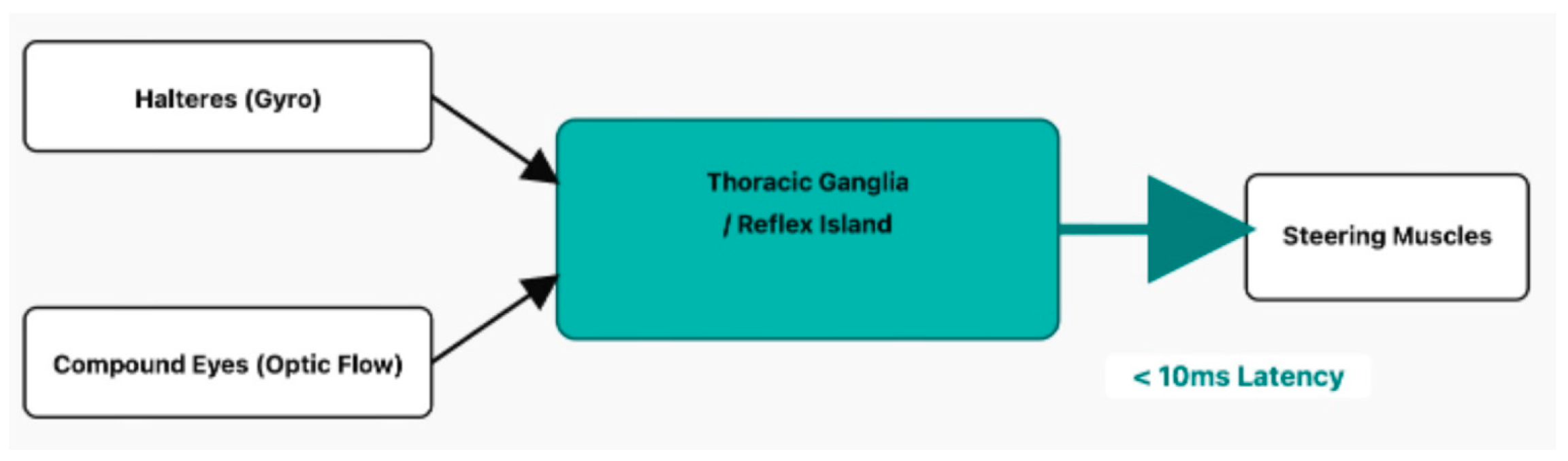
Core Concept: A minimalist, hard-real-time control loop where the gyroscope (Halteres) and optic flow (Eyes) are fused to control the wings.
- Sensing: The halteres detect angular velocity via Coriolis forces, while the compound eyes detect wide-field optic flow.
- Compute (Fusion): These two streams are fused in thoracic reflex loops, creating a complementary filter where halteres handle fast perturbations and vision handles slow drift.
- Actuation: The resulting error signal directly modulates the phase and amplitude of tiny steering muscles, making micro-adjustments at each wingbeat to stabilize attitude.
1.2. The Bee (Navigation and Task Specialist)
Bees extend this basic insect template from stabilization to navigation, route planning and landing, while still operating entirely at the edge [5,6,7,8,9]. Their compound eyes and ocelli provide wide-field optic flow and sun-compass cues; antennal and mechanosensory inputs report airspeed and body posture; and the central complex and mushroom bodies integrate these streams into a compact representation of space, reward and context [5,6,7,8,9,28]. At the behavioural level, bees perform path integration, landmark-based navigation and context-dependent foraging under strong energetic constraints, suggesting a layered control strategy with distinct time-scales.
A particularly clear example is bee landing control via optic flow (Figure 1.2). As a bee approaches a surface, it does not estimate metric distance explicitly. Instead, it regulates the ratio of vertical velocity to visual angle, the optic-flow expansion rate, by modulating lift: when the flow expands too quickly, the bee increases upward thrust to brake the descent; when it expands too slowly, it allows gravity to pull it in, producing a smooth, approximately constant-flow touchdown [6]. This heuristic-based controller can be implemented with simple non-linear operations on local motion signals, yet yields robust “soft landing” behaviour over a wide range of approach speeds and surface geometries [6,7,8,9]. It is therefore a natural template for neuromorphic landing and collision-avoidance circuits.
At a slower time scale, bees use the mushroom bodies and central complex to build and refine representations of routes, flowers and colony needs; they adjust thresholds, exploration policies and route preferences based on experience, and may even communicate profitable foraging locations via waggle-dance-like mechanisms [5,6,7,8,9,28]. This higher-level navigation and learning layer corresponds closely to what we call the Policy Tier in our architecture: it shapes goals, constraints and gain schedules for the Reflex Tier (e.g., acceptable approach angles, “no-go” directions, preferred energy budgets), but is not itself required to operate within strict millisecond deadlines.
Edge-AI lesson. The bee exemplifies a multi-scale control hierarchy: fast optic-flow and mechanosensory reflexes for collision avoidance and landing, layered under slower, plastic policies for route planning, context and reward. Figure 1.2 explicitly maps this to our engineering template: environmental stimuli impinge on sensors whose signals are first processed by a Neuromorphic Reflex Island (implementing fast, time-bounded control laws such as looming detection and landing heuristics), while a separate Policy Tier—running conventional or neuromorphic algorithms—updates goals and constraints on longer time scales. This pattern is directly applicable to edge-AI systems such as cargo e-bikes, UAVs and distributed propulsion modules, where an insect-inspired Reflex Tier can maintain basic safety envelopes even if the higher-level policy layer is delayed, degraded or temporarily offline.
Figure 1.2.
Bee navigation and task hierarchy: Reflex vs Policy. Schematic overview of how multi-modal sensing in bees (wide-field vision, polarized-sky compass, odor and wind cues) feeds into fast navigation Reflex pathways and slower Policy/Task pathways in the brain [6,7,8,9,28]. The upper “Reflex Tier” slice captures short-latency loops for corridor centering, obstacle avoidance and landing (optic-flow-based heuristics and mechanosensory feedback). The lower “Policy Tier” slice summarizes slower path integration, route memory, and value-based foraging decisions implemented in the central complex and mushroom bodies. Actions (flight path, task switching, waggle communication) emerge from the combined influence of these tiers, providing the biological template for our engineering Reflex Islands and Policy layer.
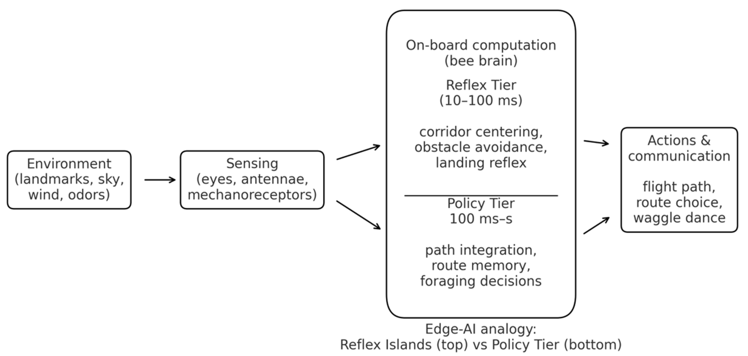
Figure 3, Figure 4 and Figure 5 provide zoom-in examples of specific modules within this hierarchy: the optic-flow landing Reflex (Figure 3), the polarized-sky compass feeding the Policy Tier (Figure 4), and the central-complex head-direction ring attractor acting as a Policy state variable (Figure 5).
Sensing: As the bee approaches a surface, the visual image of the ground expands on its retina. The rate of this expansion (dalpha/dt) is computed.
- Policy: The bee's control policy is a simple heuristic: "Modulate thrust to keep the optic expansion rate constant."
- Actuation: If expansion is too fast, the bee increases thrust; if too slow, it decreases thrust.
This simple, non-linear control loop automatically results in a smooth, decelerating touchdown without needing to know its absolute altitude h.
Sensing: UV photoreceptors in the dorsal rim of the compound eye detect the pattern of polarized light in the sky, which is fixed relative to the sun's position.
- Compute (Integration): Specialized neural circuits integrate the e-vector orientation to maintain a stable global heading, even when the sun is obscured.
- Policy: This stable heading signal feeds into the Policy Tier (Central Complex) to bias the path integration and course selection, providing a low-cost, long-range compass.
- Sensing/Input: Visual and proprioceptive inputs (e.g., optic flow, haltere signals) provide cues about angular velocity and landmarks.
- Compute (Ring Attractor): The Central Complex (specifically the Protocerebral Bridge) implements a recurrent neural network known as a ring attractor.
- This circuit maintains a persistent "bump" of activity that represents the animal's current heading.
- Policy: The position of the bump acts as a stable, internal state variable, a heading set-point that biases downstream motor reflexes, separating the high-level goal (direction) from low-level execution (torque).
2. Latency-First Architecture (Biology → Engineering)
The insect case studies above suggest a simple but powerful architectural pattern: time-critical stabilization and safety are handled by short, local reflex pathways, while slower, more flexible circuits handle mapping, planning and learning [1,2,3,4,5,6,7,8,9]. In flies, the haltere–thoracic loops that stabilize attitude run over only a few synapses and operate at the wingbeat frequency; in bees, landing and obstacle-avoidance heuristics act on optic flow within tens of milliseconds, while route planning and task selection occur over seconds to minutes [5,6,7,8,9,28]. This strict separation by time scale and function is not an aesthetic accident: it is a necessity under severe metabolic, thermal and size constraints.
For safety-critical edge-AI systems, we adopt this latency-first logic as our organizing principle. Rather than viewing the system as a single monolithic controller, we explicitly partition it into two interacting tiers:
- a fast Reflex Tier, co-located with sensors and actuators, responsible for stabilization and immediate safety, with tight worst-case execution-time (WCET) envelopes; and
The key design question then becomes: what must run in the Reflex Tier to guarantee safety under worst-case conditions, and what can safely be relegated to the Policy Tier without compromising deadlines? Insects answer this question through evolution; in engineering we answer it through WCET analysis, freedom-from-interference (FFI) partitioning, and explicit timing budgets. The remainder of this section translates the biological two-tier pattern into such an engineering template.
2.1. Two-Tier Control: From Biological Hierarchy to WCET Envelopes
Table 2.1 summarizes the qualitative correspondence between biological and engineering tiers in the insect-inspired architecture:
- The Reflex Tier corresponds to the haltere–thoracic loops of flies or the optic-flow landing controller of bees: short-path circuits that transform a small set of sensor streams into actuator commands within microseconds to milliseconds, handling stabilization, collision avoidance and other “must-not-miss” reactions. In our engineering instantiation this becomes a Reflex Island (typically a neuromorphic/spintronic partition) placed physically near sensors and drivers, with hard deadlines and minimal internal state.
- The Policy Tier corresponds to the central complex and mushroom bodies: circuits that integrate many cues, maintain internal state (e.g. head-direction bumps, value associations), and shape behaviour over tens to hundreds of milliseconds and beyond [5,6,7,8,9]. In engineering terms this is a real-time core, NPU or small cluster that runs mapping, heuristics and learning, and emits only goal states (speed corridors, thrust limits, route waypoints) to the Reflex Tier [4,5,10,11].
We therefore propose an explicit two-tier decomposition for safety-critical edge-AI control:
- The Reflex Tier (µs–ms) is located as close as possible to sensors and actuators; it runs on a pinned core or dedicated neuromorphic/spintronic die, uses fixed-priority scheduling, no dynamic memory, and one-way, lock-free single-producer/single-consumer queues for communication. It is the only place where plant-stabilizing loops (thrust, torque, braking, steering) are closed.
- The Policy Tier (ms–s) runs at lower priority on separate cores or tiles; it may use more complex software stacks, but its influence on the plant is strictly mediated through low-rate set-points and mode flags. Faults or jitter in Policy must not be able to delay or pre-empt Reflex work (FFI).
Design principles that follow from this decomposition are:
- co-locate sensors, Reflex compute and drivers;
- wire interrupt → DMA → neuromorphic Reflex → RT core → PWM/FOC in a fixed pipeline;
- keep end-to-end stabilization loops below ≈5 ms, with the most critical safety paths below 1 ms; and
- expose only goal states upstream, not raw sensor streams or inner-loop variables.
To make these ideas concrete and amenable to safety arguments, we attach WCET envelopes to each Reflex loop. Table 2.1 provides an illustrative example for a reference stabilization loop inspired by “haltere + optic flow → steering muscles”, instantiated on a representative automotive-class stack (AURIX-class MCU, MRAM device and a Loihi-class SNN core) [4,5,10,11]. Times are worst-case at the hot electrical corner (high temperature, low supply voltage) and include conservative guard bands:

Table 2.1.
– Example Reflex-loop WCET breakdown (optic flow + IMU → steering PWM).
| Stage | Function (example stack) | WCET (µs) | Cumulative (µs) |
|---|---|---|---|
| 1 | DVS/IMU exposure → interrupt assertion | 50 | 50 |
| 2 | DMA + time-stamp + spike encoding into Reflex Island | 150 | 200 |
| 3 | FF-SNN layer 1 (elementary motion detectors) | 800 | 1,000 |
| 4 | STNO reservoir / RSNN update + readout | 1,200 | 2,200 |
| 5 | Reflex decision logic + watchdog comparators | 400 | 2,600 |
| 6 | RT core arbitration, FOC current reference update | 400 | 3,000 |
| 7 | PWM/timer update + gate-driver propagation | 400 | 3,400 |
In this representative design point, the cumulative Reflex WCET is about 3.4 ms against a 5 ms design budget, leaving ≈32% margin; critical hard-wired safety paths (e.g. limit switch or E-stop → power stage) bypass the neuromorphic layers and are kept below 1 ms. The numerical values are not intended as a new benchmark; rather, they show how a biologically inspired two-tier hierarchy naturally leads to an analyzable timing structure, where each stage from sensor exposure to actuator update has an explicit WCET and margin, and where the Reflex Tier remains small, inspectable and certifiable.
3. Neuromorphic and Spintronic Hardware
The latency-first architecture of Section 2 assumes the existence of a physical substrate on which Reflex Islands can run with predictable timing, low energy per event, and minimal data movement. Insects achieve this by co-locating sensing, computation and actuation within a few synapses and millimetres; in electronics, the closest analogues are neuromorphic processors and spintronic devices that place memory and computation side by side [10,11,12,13,14,15,16,56,62,63,64,65,66,67].
In this section we do not propose a single “magic chip”, but rather a design lane: neuromorphic cores implement the spiking, event-driven Reflex Tier, while spintronic memories and oscillators provide non-volatile synapses and compact temporal reservoirs. The result is a family of possible Reflex substrates (CMOS-only, CMOS+MRAM, CMOS+MRAM+STNO), all of which share the same architectural properties: event-driven operation, non-volatility where it matters, and analyzable worst-case behaviour. Figure 6 summarizes one such stack, from event-based sensors through MRAM synapses and STNO reservoirs to a deterministic real-time core.
3.1. Why Neuromorphic Matches the Insect Edge
Spiking Neural Networks (SNNs) are the natural computational model for the insect-inspired Reflex Tier. Like insect circuits, SNNs process events in time rather than dense frames: computation is triggered only by significant changes in the input, not by a global clock [12,13,14]. This event-driven nature reduces data movement and static power, while preserving the microsecond–millisecond responsiveness needed for stabilization and collision-avoidance reflexes. Temporal coding, recurrent dynamics and oscillations—features that in biology underpin central pattern generators and phase control—are native to SNNs rather than add-ons [12,13,14].
Neuromorphic chips implement SNNs in hardware by co-locating memory and compute. Synaptic weights are stored close to, or inside, the neuron circuits; routing is sparse and event-based; and plasticity, when enabled, can be local (e.g. STDP-like rules) rather than cloud-mediated. This mirrors the insect situation where associative learning in mushroom bodies happens “on-device” and does not require shipping raw sensor data elsewhere [5,6,7,8,9,59,60]. From the Reflex-Island point of view, this memory-centric layout directly attacks the dominant cost in conventional microcontrollers and NPUs: moving data between distant SRAM/DRAM and a central core.
For the Reflex Tier we advocate a hybrid neuromorphic design:
- a feed-forward SNN (FF-SNN) front-end that performs rapid event filtering and early feature extraction (e.g. elementary motion detectors for optic flow, looming detectors for collision), and
- a small recurrent SNN / reservoir that integrates multiple modalities (e.g. visual flow + inertial signals) and implements the stateful part of the reflex (e.g. complementary filters, phase-locked loops, simple internal variables).
Benchmarks for this path are dictated by biology and safety rather than by ImageNet: an end-to-end Reflex WCET < 5 ms, with the neuromorphic portion contributing on the order of 1–2 ms, and total Reflex-loop power in the sub-milliwatt range for typical operating conditions. These numbers are consistent with the example WCET budget in Table 2 and are meant as targets for design and certification, not as achieved silicon results.
Importantly, the neuromorphic approach is no longer speculative. Several platforms have already demonstrated large-scale spiking computation at low power: Intel’s Loihi chips with on-chip learning [55], the SpiNNaker many-core machine [62], IBM’s TrueNorth neurosynaptic processor [63], and BrainChip’s Akida edge SoC [64]. They differ widely in implementation (digital vs mixed-signal, routing schemes, plasticity support), but they collectively prove that event-driven SNNs can be deployed on non-trivial problems with milliwatt–watt power envelopes. We therefore treat neuromorphic hardware as a practical substrate for Reflex Islands, not a distant aspiration: our architecture can be instantiated on any of these platforms, or on future derivatives, provided they expose sufficient timing determinism to support WCET envelopes.
In summary, neuromorphic processors give us the computational side of the insect template: local, event-driven, memory-centric processing that is naturally expressed in terms of spikes and delays, and that can be constrained to small, inspectable networks suitable for safety-critical reflexes.
3.2. Spintronic Primitives as "Physical Synapses and Neurons"
Spintronic devices complement neuromorphic processors by supplying physical, non-volatile synapses and compact temporal reservoirs. Their key property is not higher clock frequency, but a memory-centric character: they blur the distinction between “where we store weights” and “where we compute with them” [10,15,16,56]. This is precisely the bottleneck insects avoid by keeping neural pathways short and local.
In our roadmap, the spintronic–neuromorphic stack for a Reflex Island is built from two main components:
- 1)
- ○
- Instant-on innate memory. The Reflex network’s weights persist with no standby power. When an event arrives, say, from an event camera or IMU, the island is ready to respond immediately, with no DRAM refresh or flash warm-up. This mimics biological “innate reflexes” that are present and usable as soon as the organism is awake.
- ○
- Energy efficiency and robustness. Eliminating continuous refresh and long erase/program cycles reduces energy and simplifies timing analysis, because memory access times are stable across the device’s lifetime.
In practice, MRAM is already being adopted in automotive microcontrollers as a code and data store, precisely because it combines non-volatility, endurance and fast access. This trend is important for our purposes: the same MRAM array can hold both Reflex code and parameters, enabling fast, robust over-the-air updates. A/B firmware images, safe rollback and partial parameter updates become simpler and more reliable than with Flash, which suffers from wear-out and long page erases. For safety-critical edge controllers that must evolve over their lifetime (new health-monitoring features, new mission profiles) while remaining certifiable, this MRAM-based update path is as important as its raw memory properties.
- 2.
- STNO neurons / reservoirs. Spin-Torque Nano-Oscillators (STNOs) are nanoscale magnetic oscillators that can operate at GHz frequencies and exhibit rich, nonlinear dynamics [10,15,16,56]. When coupled into networks, they form physical reservoirs that process temporal streams (e.g., IMU, event camera outputs) by mapping them into high-dimensional, time-varying patterns. Readout circuits then learn simple linear or shallow nonlinear combinations of these patterns to implement the required reflex mapping. This is closely aligned with tasks such as optic-flow analysis, vibration-based anomaly detection, or haltere–visual fusion, where temporal structure matters at sub-millisecond scales.
Together, MRAM synapses and STNO reservoirs yield a memory-centric, event-driven, instant-on Reflex substrate that is well matched to the insect blueprint: non-volatile “innate” weights; rich temporal dynamics for integrating fast sensory streams; and a strong bias towards local computation. Critically, this stack is already present in industrial roadmaps: neuromorphic spintronics is featured in the IRDS “Emerging Research Devices/Beyond CMOS” chapter, the 2022 Roadmap on Neuromorphic Computing and Engineering, and the SRC/SIA Decadal Plan for Semiconductors as a leading candidate for ultra-low-power computing [56,65,66,67].
At the same time, our roadmap remains explicit about technology readiness. Embedded STT-MRAM is at high TRL (8–9) and in volume production at major foundries; it can be exploited immediately as a synaptic substrate and code store. By contrast, dense STNO reservoirs and large spin-neuron fabrics are still at mid-TRL (≈4–5): integration with CMOS, control of variability and noise, and scalable coupling remain open engineering problems. For this reason we treat the full “MRAM+STNO Reflex Island” as a near- to mid-term target: integrated lab prototypes (TRL 5–6) in the next few years, initial deployment in niche, latency-critical domains (micro-robotics, medical sensing) thereafter, and broader use only as manufacturing and modelling mature.
Figure 6 situates these elements in the system stack: event streams from sensors are converted into spikes and fed into a neuromorphic core whose weights reside in MRAM; optionally, an STNO reservoir provides additional temporal richness; the resulting Reflex outputs (set-points, torque or thrust commands, safety flags) are handed to a deterministic real-time core that performs the final control-law computation and drives the actuators. This arrangement preserves the architectural properties laid out in Section 2, tight WCET envelopes, clear Reflex/Policy separation, while grounding them in device technologies that are both biomimetically motivated and industrially plausible.
- Sensing: Event streams from sensors (e.g., event cameras, IMU) are converted into spikes (electrical pulses).
- Compute (MRAM Synapses): Magnetic Tunnel Junctions (MTJs) in MRAM act as non-volatile synapses, storing neural network weights directly where they are used. This enables instant-on capability and near-zero standby power, emulating innate memory and reflexes.
- Compute (STNO Neurons): Spin-Torque Nano-Oscillators (STNOs) act as compact, high-frequency (GHz) spiking neurons. They can form reservoirs for processing temporal tasks and sensorimotor transformation, such as optic flow analysis.
- Actuation (RT Core): The output (set-points) of the spintronic SNN feeds a deterministic Real-Time Core (RT Core) that performs final control (PID/LQR) and drives the actuators.
4. Thermoregulation, Frequency Control, and “Natural Engine” Analogies
Small flyers live on an unforgiving surface-to-volume battlefield: heat is generated in proportion to volume but lost through surface area, so small bodies heat up and cool down much faster than large ones [21,22,23,24,25,26]. Insects nevertheless maintain their flight muscles within a tight temperature band, and many species show only modest variation in mechanical efficiency across a wide power range, in contrast to the narrow best-efficiency islands of internal combustion engines and miniturbines [21,22,23,24,32,33,34,35,36,37,52,53,54].
In this section we deliberately adopt a schematic, roadmap style. Rather than attempting a full thermodynamic or physiological meta-analysis, we extract a few robust biological mechanisms, Discontinuous Gas Exchange (DGC) for respiration and thoracic thermoregulation for heat management—and reinterpret them as design heuristics for I/O gating, burst budgeting, and thermal governance in edge-AI electronics and propulsion. Sections 4.3, Sections 4.4 and Sections 4.5 then connect this to scaling laws and efficiency maps, and Section 5 uses these analogies to motivate an insect-like “natural engine” behaviour in fuel-based thrusters.
4.1. Discontinuous Gas Exchange (DGC) and Idle I/O Gating
At rest, many insects do not breathe continuously. Instead, they employ Discontinuous Gas Exchange (DGC): a stereotyped spiracle cycle with three phases, Closed → Flutter → Open, that satisfies oxygen demand while minimizing water loss and oxidative damage [17,18,19,20]. In the Closed phase, spiracles remain shut and gas exchange is almost zero; in the Flutter phase, spiracles open and close rapidly with a low duty cycle, allowing small “test” inflows of O₂ and outflows of CO₂; only in the Open phase do they fully open, releasing accumulated CO₂ in a brief burst [17,18,19,20]. Physiologically, this pattern reduces evaporative water loss, limits exposure to high internal O₂ partial pressures and reactive oxygen species, and still meets metabolic needs at rest or low activity [17,18,19,20].
For edge-AI systems, we adopt DGC as a biomimetic template for I/O and compute gating:
- Closed ≙ deep idle. All non-essential interfaces are off; only an ultra-low-power time base or simple wake-up detector (e.g., RTC, threshold comparator) remains active. No sensor data are streamed; no neuromorphic or RT core is clocked.
- Flutter ≙ duty-cycled health checks. Short, low-duty bursts of sensing and computation verify liveness and environmental state: a brief sensor read, a minimal anomaly detector run, then return to Closed if nothing demands action. Total average duty cycle is kept very low, analogous to the low spiracle duty factor in DGC.
- Open ≙ full bandwidth on demand. When a relevant event is detected, e.g., a looming obstacle, threshold overshoot, or external wake-up, the system transitions to full-rate sensing and Reflex processing, analogous to the Open phase’s full spiracle opening.
In the Reflex/Policy architecture, DGC-style gating applies at multiple levels:
- Sensor interfaces (camera, IMU, pressure, acoustic): event-driven or frame-based acquisition is fully off in Closed, lightly sampled in Flutter, and fully active only in Open.
- Neuromorphic Reflex Islands: synaptic weights remain resident in MRAM, but neuron arrays and on-chip routing are clock-gated except during Flutter or Open windows.
- Policy Tier: can remain entirely off in Closed and much of Flutter, only waking when the Reflex Tier raises a “need context” flag.
The DGC analogy thus provides a simple design pattern for extreme low-power operation: keep everything that is not immediately needed in a Closed state, allow only intermittent Flutter-checks at very low duty cycle, and enter Open only under well-defined, Reflex-driven conditions. For medical implants or always-on safety systems (Section 5.3), this DGC-style I/O gating can be crucial for multi-year operation on limited energy reserves while still guaranteeing immediate responsiveness when it matters.
4.2. Thermal Governance as a State Machine
Gas exchange is only half of the story; temperature control is equally critical. Insects actively thermoregulate during all phases of operation. Resting bumblebees and honeybees sit with body temperature close to ambient, but before take-off they shiver their flight muscles to warm the thorax into a narrow performance band (typically ≥30 °C and often 35–40 °C), then hold that thoracic temperature roughly constant during flight over a wide range of ambient conditions [21,22,23,24]. Ventilatory and evaporative cooling, head–thorax heat partitioning, and behavioural strategies (clustering, wing-fanning) are deployed to export excess heat and protect neural function in the head [21,22,23,24].
The key engineering insight is that insects largely decouple output power from efficiency: by actively maintaining muscle temperature in its biomechanical “sweet spot”, they can vary power output mostly through wingbeat frequency and stroke amplitude, without strongly sacrificing intrinsic mechanical efficiency over the relevant operating range [21,22,23,24,32,33,34,35,52,53,54]. In contrast, internal combustion engines and miniturbines have narrow best-efficiency islands tied to specific power–rpm points, and efficiency falls steeply away from those islands [36,37]. Thermoregulation thus acts as a governor: it keeps the biological engine near its optimal island and lets the system modulate power with minimal efficiency penalty.
We translate this into a state-dependent thermal governance scheme for edge-AI hardware, especially for compact Reflex Islands with significant local power density. Conceptually, we organise thermal behaviour into a firmware state machine:
- REST. All but the most basic sensing (e.g., temperature/voltage monitors) and Reflex loops are quiescent; the system tracks ambient temperature and internal temperature but generates little heat.
- WARM-UP. On a demand for performance (e.g., activation of a thruster or high-load compute), the system proactively raises the temperature of the critical component cluster (e.g., neuromorphic/spintronic die, power stage) towards a set-point where timing and efficiency are optimal, analogous to shivering thermogenesis in bees [21,22,23].
- WORK. The system operates within its continuous-power envelope: clocks and currents are chosen so that average power dissipation does not exceed steady-state cooling capacity; temperature hovers near the set-point.
- BURST. For short intervals, the system is allowed to exceed its steady-state thermal budget—e.g., higher current to actuators or boosted compute frequency, drawing on the thermal capacitance of the hardware stack. The allowable burst duration depends on a simple lumped thermal model (time constant τ) and the current thermal debt (difference between current temperature and set-point), as worked out explicitly in Section 4.3.
- COOL-DOWN. After a burst, loads are reduced and cooling (convection, conduction, fan speed) is increased to “repay” thermal debt and return to the set-point without overshoot.
- FAULT-SAFE. If temperature approaches a critical limit Tcrit despite COOL-DOWN actions—or if sensors fail—the system enters a safe state: Reflex safety loops remain alive, but all non-essential Policy and high-power functions are shed.
In control terms, burst budgeting is implemented as a predictive loop. For a given planned power level and a lumped thermal capacitance and conductance (formalised in Section 4.3), the controller computes a maximum burst duration such that the predicted temperature trajectory never exceeds . During operation, this prediction is continuously corrected using measured temperature and ambient conditions . A convenient internal variable is the thermal debt,
which encodes how far the system is from its optimal band. Large positive shrinks the permissible or blocks BURST entry altogether; negative or small
Crucially, this state machine is aligned with the Reflex/Policy hierarchy: Reflex loops (e.g., stabilization, collision avoidance, basic thrust control) must remain live in all states except catastrophic FAULT-SAFE, while Policy tasks (mapping, learning, high-level planning) are the first to be throttled or suspended when thermal margins shrink. Insects show the same priority: they continue to stabilise flight and navigate even as they shed optional behaviours under thermal stress [21,22,23,24].
In this way, insect thermoregulation becomes a concrete recipe for thermal-aware scheduling and power management in edge-AI hardware: maintain a narrow thermal band for critical Reflex computation, use predictive burst budgeting to exploit thermal capacitance without violating limits, and always sacrifice Policy performance before Reflex safety when resources become constrained.
4.3. Why Thermoregulation Tightens at Small Scale (Black-Body + Convection)
Small flyers operate on a brutal surface-to-volume battlefield: heat is generated in proportion to volume but lost through surface area. As characteristic size shrinks, the ratio grows and thermal time constants collapse; small bodies heat up and cool down much faster than large ones, making passive thermal inertia insufficient to keep performance-critical tissues in their optimal band [25,26].
We capture this with a lumped heat balance for a body at core temperature and ambient
where is the thermal capacitance of the body, is the convective heat-transfer coefficient, is the exposed surface area, the emissivity, and the Stefan–Boltzmann constant [25,26]. The right-hand side balances internally generated power against convective and radiative losses.
For modest temperature excursions around ambient, radiation can be linearized:
so convection and radiation combine into a single cooling conductance
and the dynamics reduce to a first-order form
with thermal time constant
If we take a characteristic length such that surface area scales as and volume (hence ) as , then
up to the factor [25,26]. In other words, smaller bodies (smaller ) yield smaller : they equilibrate thermally much faster. At insect scale, this means an unregulated thorax would track ambient temperature on timescales comparable to, or shorter than, behavioural timescales; precise flight and neural timing would be impossible without active thermoregulation [21,22,23,24].
Figure 7 summarizes this scaling: internal power flows into a “body” node, while convection and radiation drain it through a combined conductance . As the characteristic length decreases, the area-to-volume ratio grows, rises faster than , and the thermal time constant shrinks. For insects, this shrinking is not just an annoyance: it forces the evolution of mechanisms like shivering warm-up, ventilatory and evaporative cooling, and head–thorax temperature partitioning to keep flight muscles within a narrow performance band [21,22,23,24]. For engineered edge-AI hardware, the same scaling warns that small, dense chiplets and power stages cannot rely on passive thermal inertia, they too require explicit thermal governance and burst budgeting (as formalised in Section 4.2 and 4.8).
4.4. A Four-Stroke “Natural Engine” for Insect Thermoregulation
Insects do not run a crankshaft, and their thermoregulation is essentially continuous; nevertheless, it is often useful, especially for engineers, to recast their thermal cycles in a four-stroke metaphor. The goal is not mechanical equivalence, but a conceptual bridge to firmware state machines and engine-control intuition (Section 4.2, Figure 8).
We therefore describe insect thermoregulation as a “natural engine” with four abstract strokes:
- WARM-UP (Compression). Shivering thermogenesis in the flight muscles raises thoracic temperature towards a narrow performance band (≈30–40 °C in bees), while the head is kept relatively cooler to protect neural timing [21,22,23]. This corresponds to building up “thermal pressure” before high-power operation.
- WORK / BURST (Power). Wing actuation now couples mechanical work to ventilation and evaporative cooling. As flight intensity increases, both convective and evaporative heat export scale with effort, helping to hold the thorax near its set-point despite higher internal Pint [21,22,23,24]. This is the main “power stroke” where muscle efficiency remains near optimal while output power is modulated primarily by wingbeat frequency and stroke (Section 4.5).
Figure 8 overlays this four-stroke view onto a state-dependent thermal-control system: thoracic and ambient temperatures are sensed; a central controller (insects: distributed neural and hormonal circuits; engineering: firmware state machine) regulates both heat production (e.g., shivering, muscle activation) and heat dissipation (ventilation, evaporative cooling, head cooling) to maintain the thoracic set-point. In our edge-AI analogy, the same four logical strokes map onto the REST → WARM-UP → WORK/BURST → COOL-DOWN states of Section 4.2, where dynamic voltage and frequency scaling (DVFS), workload scheduling, and sensor duty cycles are orchestrated to allow short high-performance bursts without crossing critical thermal limits.
This “natural engine” metaphor dovetails with Section 4.5 and Section 5.1: whereas conventional ICEs and miniturbines exhibit narrow efficiency islands determined by geometric and thermodynamic constraints, insects use thermoregulation plus frequency control to maintain near-constant mechanical efficiency over a broad power range [21,22,23,24,32,33,34,35,52,53,54]. The four logical strokes identified here become the firmware hooks for implementing similar behaviour in edge-AI hardware and fuel-based propulsion: explicit REST and WARM-UP phases; controlled entry into BURST based on a thermal budget; and COOL-DOWN trajectories that repay thermal debt while preserving Reflex safety.
- Sensing: Thoracic temperature (for power output) and ambient temperature are monitored.
- Compute (Control): A central control mechanism (analogous to a firmware state machine) actively regulates heat production (e.g., shivering) and heat dissipation (e.g., head cooling/evaporative cooling) to maintain a performance-optimal thoracic temperature set-point.
- Engineering Analogy: This is mirrored by an Edge AI system's thermal governance, which uses a state machine to dynamically adjust power/clock frequency (DVFS) and sensor duty cycles based on thermal sensors and predicted load, allowing for short, high-performance bursts while preventing thermal runaway.
4.5. Propulsion Analogy: Injection/Wingbeat Frequency and Efficiency
Thermal governance (Section 4.2, Section 4.3 and Section 4.4) keeps insect flight muscle in a narrow temperature band where its biomechanical efficiency is close to optimal. Within that band, power output is modulated primarily by actuation frequency and stroke amplitude rather than by large excursions in thermodynamic state [21,22,23,24,32,33,34,35]. In other words, insects largely decouple “how hot the engine runs” from “how much thrust it produces”: once the thorax is warm, the muscle converts metabolic power to mechanical work with only modest efficiency variation across the functional load range.
In this section we build a propulsion analogy in three steps:
- in Section 4.5.1 we recall that modern common-rail engines already operate their injectors at command frequencies in the same 10²–10³ Hz decade as insect wingbeats;
- in Section 4.5.2 we note that insect wingbeat frequency itself lives in that same band, but arises from asynchronous muscle and thorax resonance rather than a central clock; and
- in Section 4.5.3 we compare efficiency maps of conventional engines and miniturbines against insect flight muscle, motivating the “flat-band, frequency-governed” behaviour we seek in insect-inspired thrusters.
Figure 9 then summarizes the efficiency comparison, while Figure 10 provides a time-domain view of thermoregulation during flight that underpins the four-stroke “natural engine” metaphor introduced in Section 4.4 and reused later in Section 5.
4.5.1. Injection Event Frequency in ICEs
In a four-stroke reciprocating engine, each cylinder experiences one combustion event every two crankshaft revolutions. If each event uses micro-injections (pilot, main, post, etc.), the per-cylinder injector command frequency is
and for an even-fire engine with cylinders the aggregate scheduling rate seen by the ECU is
Examples. At 8000 rpm with and
- per cylinder: ;
-
aggregate: .At 2000 rpm with the same
- per cylinder: ;
- aggregate: .
Thus modern multi-pulse injection strategies operate squarely in the 10²–10³ Hz decade at typical speeds [27,28,29,30,31]. Multiple injections (pilot/main/post; up to 5–8 pulses per event) are used to shape heat release for emissions and noise control, but they do not fundamentally alter the thermodynamic best-efficiency island of the engine [27,28,29,30,31]: they refine combustion phasing and pressure rise, but the basic narrow-peak efficiency map remains (see Section 4.5.3).
From our perspective, this subsection establishes that “control knobs” running at a few hundred hertz are already standard in automotive propulsion, the same bandwidth where insects control wingbeat frequency. The key difference is that in engines, changing this knob does not flatten the efficiency map; in insects, frequency control plus thermoregulation yields a much flatter efficiency band.
4.5.2. Wingbeat Frequency in Insects
Insects operate their wings at similar absolute frequencies to those injector command rates, but via very different mechanisms. Wingbeat falls in the same 10²–10³ Hz decade but is produced by asynchronous flight muscle and thorax resonance: neural spikes gate contractions while frequency stems from elastic mechanics, enabling high-Q operation with modest compute. Honeybees hover at ≈230 Hz [32,33,34,35], some small dipterans exceed 1 kHz [32,33], larger insects beat more slowly but still well into the tens–hundreds of hertz range [32,33,34,35].
Crucially, this frequency is not directly imposed by a central neural clock firing at 200–1000 Hz. Instead, many insects rely on asynchronous flight muscle and thorax resonance:
- neural spikes gate contractions and set overall activation level,
This combination allows insects to:
- achieve high wingbeat frequencies with modest neural bandwidth and energy per spike,
- modulate power output primarily by changing frequency and stroke amplitude within a thermally managed band, and
In other words, insects solve with mechanics and thermoregulation what engines attempt to solve with high-rate, centrally scheduled injection. Where ICE injection scheduling demonstrates that 10²–10³ Hz control is technologically routine, insect wingbeat shows that frequency-governed actuation can be both energetically efficient and mechanically robust when coupled to appropriate structures and thermal control.
Edge-AI lesson. For engineered systems, this suggests a design pattern where prime movers (engines, thrusters, actuators) are held near an optimal efficiency state, while thrust or torque is modulated by frequency or duty cycle of a mechanically resonant element (motor, fan, pump-jet), rather than by dragging the thermodynamic cycle across a wide operating range. Section 5.1 leverages this by proposing frequency-controlled electric propulsors fed by a prime mover parked on its efficiency island.
4.5.3. Efficiency Maps: Narrow Islands vs Near-Flat Bands
ICEs (and Brayton turbines) exhibit narrow best-efficiency islands: regions of low brake-specific fuel consumption (BSFC) or high thermal efficiency that occur at specific combinations of torque and rpm [36,37]. Moving away from these islands, especially towards low load, induces pumping losses, incomplete expansion and increased relative heat losses. Adjusting injection/ignition timing or increasing pulse frequency improves emissions and noise, but does not flatten the underlying thermodynamic map [27,36,37].
Insects, by contrast, regulate power primarily by wingbeat frequency and stroke while maintaining thoracic temperature near an optimal set-point (Section 4.2, Section 4.3 and Section 4.4), so mechanical conversion efficiency varies only modestly across the functional range. Classical work-loop and respirometry studies [52,53,54] report mechanical efficiencies for flight muscle in the ~10–15% range for several species and preparations, even as mechanical power output and wingbeat frequency vary by factors of three to four [32,33,34,35]. Ellington [53] reports a calculated upper limit of ≈29% for hovering flight-muscle efficiency if elastic storage is ignored, challenging earlier low-efficiency assumptions. Syme and co-workers report asynchronous flight muscle efficiencies in the 15–20% range, underscoring that this muscle type is highly evolved for mechanical output [35,70,71].
Rather than attempt a precise meta-analysis of heterogeneous experimental protocols, we summarize these data schematically in Figure 9 as a shaded efficiency band between ~10% and 15% across a broad span of normalized mechanical power. Coloured symbols indicate representative points digitized from Weis-Fogh [52], Ellington [53], Harrison & Roberts [54], Josephson and Marden [70,71]. The curves for diesel/gasoline engines and miniturbines are likewise schematic, drawn from standard BSFC maps and microturbine data [36,37,38,39,40,41,42,43]. The qualitative picture is robust:
- Engines and miniturbines: high peak efficiency (≈40–45% for modern diesel; ≈20–25% for 200–400 N miniturbines) but confined to narrow islands in normalized power, with steep penalties at low load and noticeable degradation at the extremes.
- Insect flight muscle: lower absolute efficiency (10–15%), but comparatively weak load dependence over the biologically relevant range; small excursions at very low or very high loads, but no sharp peak like in ICEs.
Insect flight muscle, particularly asynchronous flight muscle in flies, bees and wasps, is therefore a temperature-dependent, efficiency-plateau machine. Its enzymes and contractile filaments are tuned to operate at a specific elevated thoracic temperature (≈35–40 °C); active thermoregulation then keeps the muscle in this biomechanical “sweet spot” (Section 4.2, Section 4.3 and Section 4.4). Within that band, the insect adjusts mechanical power largely by changing wingbeat frequency and amplitude without sacrificing intrinsic mechanical efficiency.
From an engineering standpoint, this justifies the “near-flat band” representation adopted in Figure 9 and underpins the propulsion analogy in Section 5: we seek engineered systems whose prime movers behave more like insect flight muscle than like classical BSFC maps. Figure 10 complements this by showing a time-domain view of thoracic temperature under REST → WARM-UP → FLIGHT → COOL-DOWN cycles, annotated with the four-stroke “natural engine” metaphor introduced in Section 4.4. Together, Figure 9 and Figure 10 provide the thermodynamic template for the insect-inspired thruster and hybrid architectures developed in Section 5.
4.6. Miniturbines: Scaling Limits, High rpm, and Cold-Start Latency
Micro gas turbines and miniturbines have been widely proposed as range extenders and hybrid sources for UAVs, eVTOLs and high-endurance platforms: they offer high specific power, simple mechanics (few rotating parts), and good reliability when run near design point [36,37,38,39,40,41,42,43]. However, when viewed through the insect lens of flat efficiency bands and fast warm-up, several limitations appear:
- Low peak efficiency at relevant scales. In the 200–500 N thrust range, typical microturbines achieve only ≈20–30% thermal efficiency at or near their design point [36,37,38,39,40,41,42,43]. Combined with partial-load penalties, this translates into fuel burn significantly higher than that of best-in-class piston engines at the same useful power [36,37,38,39,40,41,42,43].
- Narrow best-efficiency island. As in larger Brayton machines, microturbines exhibit a narrow efficiency peak as a function of shaft speed and load. Operation at 30–50% of rated thrust can see efficiency degrade by tens of percent relative to the peak, exactly the regime where loiter, approach and partial-power climb occur. By contrast, insect flight muscle maintains mechanical efficiency in a relatively flat 10–15% band across its useful range (Section 4.5.3, Figure 9) [32,33,34,35,52,53,54].
- Cold-start and spool-up latency. From cold, microturbines require seconds to tens of seconds for safe ignition, acceleration and thermal stabilisation before usable power is available, and even from warm idle, spool-up to high thrust takes hundreds of milliseconds to seconds depending on inertia and control laws [36,37,38,39,40,41,42,43]. Insect flight, by contrast, is limited primarily by warm-up of the thorax (shivering) and then operates with cycle-by-cycle power modulation via wingbeat frequency, with effectively zero “spool-up” once airborne (Section 4.2, Section 4.3 and Section 4.4).
- Hot, high-speed exhaust. Microturbines typically exhaust gas at 500–1000 °C at high jet speeds, with acoustic signatures dominated by high-frequency components and potential ingestion risks in distributed configurations [36,37,38,39,40,41,42,43]. Insects, by contrast, exhaust metabolic heat via moderate temperature differentials and relatively low-speed convective and evaporative flows (Section 4.4).
These characteristics do not prevent the successful use of miniturbines in current UAVs and demonstrators, but they make them poor matches to the insect template we are pursuing:
- Efficiency is not flat across the useful thrust range.
- Burst capability is constrained by the thermal and mechanical inertia of the rotor and casing.
- Spool-up latency conflicts with the idea of “instant-on” Reflex behaviour that can support rapid manoeuvres, hopping or emergency climbs.
In Section 5.1 we therefore treat microturbines primarily as reference points, benchmarks against which an insect-inspired “natural engine” can be compared, rather than as the default solution.
The insect–engine comparison in Section 4.5 and the miniturbine limits in Section 4.6 suggest a hybrid architecture where we separate the role of the thermal prime mover from that of the distributed propulsors:
- The prime mover (piston engine, IFEVS thruster core, fuel cell, etc.) is operated as a “natural engine”: kept near its optimal efficiency band by thermal governance and modest power modulation (Section 4.2, Section 4.3 and Section 4.4).
- The distributed propulsors (electric fans, propellers, pumps, pumps-jets) are driven via electrical or mechanical power distribution networks and handle fine-grained thrust vectoring, redundancy and control authority.
In this view, the prime mover behaves like insect flight muscle plus thoracic thermoregulation; the distributed propulsors play the role of wings, each with its own local control. This yields several biomimetically motivated advantages:
- Flat-band operation of the prime mover. By designing the thermal core (e.g. an IFEVS thruster) to operate at nearly constant efficiency over a modest range of power and then using frequency or duty-cycle modulation in the electric propulsors to shape net thrust, we align hardware behaviour with the insect efficiency plateau of Figure 9 [32,33,34,35,52,53,54]. The prime mover stays in its sweet spot; the “wings” do the dynamic work.
- Fast thrust response with slow thermal dynamics. Electric propulsors respond on millisecond timescales; their Reflex loops can be implemented as neuromorphic Reflex Islands with tight WCET envelopes (Section 2, Section 3). The prime mover can ramp more slowly to follow envelope constraints and thermal budgets (Section 4.2 and Section 4.3) without compromising manoeuvre agility. This is directly analogous to insects: muscles and thorax temperature change slowly, but wingbeat frequency and stroke can change cycle-by-cycle.
- Compatibility with distributed propulsion and VTOL/eSTOL. Multiple small propulsors, arranged in wings, rings, ducts or matrices, can be controlled independently, enabling fault tolerance, smooth transitions between VTOL and eSTOL modes, and advanced noise management. Because each propulsor deals with relatively cool, low-speed flow, the integration challenges are closer to those of electric distributed propulsion (DEP), even if the upstream energy source is fuel-based [36,37,38,39,40,41,42,43].
- Clear safety interfaces. The Reflex/Policy architecture maps naturally onto this hybrid setup. Each propulsor node has a local Reflex Island that guarantees basic stability and fast reaction to failures (loss of a rotor, gusts, sensor dropouts). A small number of central Reflex nodes supervise the prime mover and power distribution, enforcing thermal and power envelopes. On top of this, a Policy Tier runs guidance and mission logic. Shared safety envelopes, thermal, power and thrust, are implemented as explicit burst budgets and WCET guarantees (Section 2, Section 4.2–Section 4.3), rather than as implicit controller tuning.
In Section 5.1 and Section 5.2 we use this pattern in two different guises: an insect-inspired fuel-based thruster feeding electric propulsors, and a solar cargo e-bike where pedal-assist, motor torque and safety shell are coordinated under a common energy and thermal budget. In both cases, the insect template, flat-band efficiency, frequency-governed actuation, explicit warm-up and burst phases, provides design targets for the hybrid propulsion system.
4.7. Thermal-Debt ODE and Burst Budgets for Engineered Systems
Section 4.2, Section 4.3 and Section 4.4 introduced a state-machine view of thermal behaviour (REST → WARM-UP → WORK/BURST → COOL-DOWN → REST) and a lumped thermal model,
with the effective thermal capacitance, the combined convective/radiative conductance, and the internal power dissipation (Section 4.3). For engineered hardware, this simple ODE is already sufficient to derive quantitative burst budgets and tie them to the state machine.
Assume that during a BURST phase the prime mover or compute island dissipates a higher power for a limited time , starting from an initial core temperature and ambient . The linear ODE has a closed-form solution:
Imposing a hard thermal limit for all yields an implicit bound on the admissible burst duration as a function of , , , , and . In practice, firmware need not solve this analytically at run time; instead, designers can:
- compute offline (with conservative parameter choices for );
- store the resulting burst budget curve (or a coarse table) in the Reflex Island; and
- have the thermal state machine consult this budget before admitting a new BURST, updating it online using the measured thermal debt
If is small or negative (core cooler than set-point), longer bursts are allowed; as grows, the allowable shrinks or becomes zero. This mirrors insect behaviour: after intense flight (large thermal debt), bees must rest or use additional cooling before flying again [21,22,23,24].
From a safety standpoint, the Reflex Tier is responsible for enforcing this thermal-debt logic:
- Reflex loops maintain stabilisation and basic control even as BURST entry is denied when thermal margins vanish;
- the Policy Tier may propose trajectories or manoeuvres that would exceed the burst budget, but these are rejected or degraded by the Reflex layer if Tdebt is too high;
- faults in temperature sensors or thermal models drop the system into a conservative mode (e.g. disallow BURST, limit continuous power).
Figure 10 (thermal time history) illustrates a typical scenario: a platform starts in REST, enters WARM-UP to reach , performs a sequence of WORK and BURST phases while the thermal-debt variable grows and shrinks, and then returns to COOL-DOWN and REST. Insects implement this pattern with shivering thermogenesis, wingbeat modulation and evaporative cooling; engineered systems implement it with DVFS, load shedding and active cooling. In both cases, the combination of thermal ODE + state machine + burst budget defines a thermodynamic contract under which the Reflex/Policy architecture can safely operate.
In Section 5.1 we apply this contract to an insect-inspired fuel-based thruster, using the ODE-based burst-budget logic to shape permissible thrust bursts and mission profiles. In Section 5.2 we reuse the same framework at a different scale for a solar cargo e-bike, where battery, PV input and motor heating define analogous energy and thermal debts.
5. Use Cases and Actionable Guidance for Adoption
5.1. Insect-Inspired Fuel-Based Thruster (IFEVS) as a Conceptual Case Study
The insect thermoregulation and efficiency patterns of Section 4 suggest a new class of fuel-based “natural engines”: prime movers that combine ICE-like peak efficiency with insect-like flat efficiency bands, and whose output can be modulated primarily through frequency and duty cycle rather than by dragging the thermodynamic cycle across a wide map. As a concrete, forward-looking example, we outline an IFEVS fuel-based thruster that is being developed separately within the IFEVS programme.
The goal of this subsection is not to present a finished propulsion product, but to show how the insect-inspired architecture could be instantiated in a fuel-based device. All performance numbers given here are therefore model-derived engineering estimates, informed by subsystem measurements, and should be read as indicative, with explicit uncertainty bands, not as final certified data. A dedicated propulsion paper will present the detailed cycle analysis, test rig, instrumentation and peer-reviewed validation.
5.1.1. Concept and Relation to the Insect Template
At a high level, the IFEVS thruster is designed to behave as a “four-stroke natural engine” in the sense of Section 4.4: its hot core is kept near an optimal thermal band, and thrust is modulated primarily via mass-flow and frequency control, not by swinging the internal thermodynamic point back and forth across a narrow efficiency island. Architecturally, it consists of:
- a fuel-burning core with no high-speed rotating machinery, where combustion is organised to favour high static-pressure recovery and moderate jet velocities;
- a compact augmenter/ejector, which entrains and accelerates ambient air, trading jet speed for mass flow and static pressure recovery; and
- a set of distributed exhaust ports that can be vectored or integrated into lifting or propulsive surfaces.
Biomimetically, the core roughly corresponds to flight muscle, the augmenter to a multi-wing system that converts muscle work into lift and thrust, and the surrounding Reflex Islands to the insect’s thoracic ganglia controlling stroke and frequency. Thermal governance (REST → WARM-UP → WORK/BURST → COOL-DOWN) follows the state-machine pattern of Section 4.2 and Section 4.8, with burst budgets derived from the same lumped thermal model used there.
5.1.2. Thermal Efficiency and Flat-Band Behaviour (Model-Based)
Preliminary cycle studies, calibrated against component-level tests, indicate that the IFEVS core can achieve a nominal thermal efficiency slightly above 40% at its design point, i.e., comparable to the peak efficiency of modern diesel engines but in a much simpler topology and at smaller scales. More importantly, when combined with the augmenting ejector and operated under the thermal-governance regime of Section 4.2 and Section 4.3, the overall thruster exhibits an approximately flat efficiency band over a broad normalized thrust range.
Figure 11 repeats the schematic efficiency comparison of Figure 9 but adds an IFEVS thruster band: a hatched region from ≈40% to ≈43% efficiency extending from ≈0.2 to 1.0 normalized thrust. Within this band:
- Core thermal efficiency varies only weakly with thrust, as long as temperature and pressure ratios are held within their designed operating window.
- The augmenter converts high-velocity core flow into higher mass flow and static pressure with relatively modest additional losses.
- Duty-cycle and “stroke” (e.g., pulsation frequency of the core, modulation of injection) modulate net thrust without materially degrading the underlying thermal conversion efficiency, as long as operation stays within the continuous WORK region of the thermal state machine.
Quantitatively, we currently characterise the thruster’s thermal–mechanical efficiency as across the 0.2–1.0 normalized thrust range. This ±5 percentage-point band explicitly reflects model uncertainty, measurement noise in subsystem tests, and conservative allowances for integration losses. The values are therefore conceptual design targets consistent with the insect-inspired “flat band” of Section 4.5, not yet a fully validated performance map.
5.1.3. Comparison with Microturbines at Equal Thrust (Table 5.1)
To give the thruster numbers context, we compare them against representative commercial microturbines in the 200–600 N thrust class (e.g., JetCat P400/P550 family), which are often proposed as hybridisation candidates for UAV and eVTOL propulsion [36,37,38,39,40,41,42,43]. For these reference devices, manufacturer data show peak thermal efficiencies in the ≈20–25% range with significant penalties at partial load.
Table 5.1 summarises a model-based fuel-flow comparison between:
- the IFEVS thruster operating at several nominal thrust levels (50 N steps from 50 N up to 600 N), and
- the corresponding JetCat P400 and P550 microturbines after accounting for their augmenters and typical partial-load behaviour.
The table lists, for each thrust level:
- the reference microturbine thrust and fuel flow (mL·min⁻¹) based on manufacturer data and standard scaling;
- the IFEVS thruster fuel flow at the same net thrust, according to the current cycle model; and
- the fuel-flow ratio .
Across the range, the model predicts:
- Around a 400 N design point, the IFEVS thruster uses roughly half the fuel of a state-of-the-art microturbine at equal net thrust.
All ratios in Table 5.1 should again be read as engineering estimates with at least ±5 percentage-point uncertainty, not as precise measurements. The main purpose of the table is to show that if a flat-band ~40% thruster can be realised at these scales, then significant fuel savings relative to current microturbines are plausible, especially in partial-load regimes typical of loiter and approach.
5.1.4. Exhaust Temperature, Acoustic Signature and Distributed Propulsion
Beyond fuel consumption, the insect template suggests advantages in exhaust temperature and acoustic signature. Insects expel heat at modest temperature differences via convective and evaporative flows rather than via extremely hot, high-speed jets (Section 4.4). The IFEVS thruster aims to emulate this by designing the augmenting ejector and nozzle system to favour low jet speeds and extensive mixing:
- The exhaust Mach number is kept subsonic at the outlet, which suppresses shock-associated noise and high-frequency components.
Concept designs therefore target ≤100 dB at 3 m in representative configurations, a dramatic reduction compared to hot supersonic microjets. The combination of cooler exhaust and lower noise simplifies integration in distributed propulsion arrays, allows closer placement to structures and people, and reduces thermal signatures. In the insect analogy, this corresponds to replacing a few scorching jets with many “wing-like” outlets that move cooler air quietly but effectively.
5.1.5. Integration with Neuromorphic Reflex Islands and Distributed Propulsion
From the edge-AI architecture perspective, the IFEVS thruster is attractive not only for its thermodynamic behaviour, but also for its compatibility with neuromorphic Reflex Islands and distributed propulsion (Section 2, Section 3 and Section 4.7):
- The thruster’s thrust is modulated primarily by frequency and duty-cycle control of fuel injection and augmenting flows, with time constants compatible with millisecond-range neuromorphic controllers. There is no heavy rotor inertia to “spool up” as in a turbine, so near-instant thrust modulation becomes feasible.
- MRAM-based Reflex Islands can host the core thrust and thermal-governance logic, with non-volatile weights and parameters enabling fast restart, deterministic timing and robust over-the-air updates (A/B images, safe rollback), as discussed in Section 3.2.
- In a distributed propulsion system, multiple IFEVS modules or a single IFEVS core feeding several electric propulsors can be controlled by a lattice of Reflex Islands, each responsible for local thrust vectoring, envelope protection and burst-budget enforcement.
Insects again provide the blueprint: wing-specific reflexes (e.g., fly haltere–thoracic loops) handle local stabilization, while the flight-muscle “engine” is governed centrally for energy and heat. The IFEVS thruster and its associated electric propulsors share the same pattern: local Reflex loops for each propulsor, a thermal and power Reflex loop around the thruster core, and a slower Policy Tier managing mission-level decisions.
5.1.6. Safety and Certification Hooks: Proposed Strategy
A key goal of this case study is to show that insect-inspired thrusters can be embedded in a certification-friendly architecture rather than being treated as exotic engines. We therefore outline a proposed safety and certification strategy, aligned with the Reflex/Policy separation and the spintronic Reflex Islands of Section 2 and Section 3:
- Fault taxonomy. We consider permanent and transient faults across sensors (pressure, temperature, flow, vibration), compute (neuromorphic/spintronic Reflex Islands, RT cores) and actuators (valves, injectors, drivers). Fault modes include stuck-at, drift, noise bursts and timing violations.
- Reflex/Policy partitioning. All safety-critical control—inner thrust loop, thermal burst budget enforcement, envelope protection (over-thrust, over-temperature, over-pressure)—is executed on Reflex Islands and dedicated RT cores with explicit WCET envelopes (Section 2.1, Table 2.1). Policy-level functions (mission planning, optimization) are treated as non-safety-critical and cannot pre-empt Reflex work.
- Fault-injection campaigns. We envisage systematic transient fault injection targeting MRAM synapses, spintronic oscillators and communication paths, and policy/reflex-boundary violations (e.g., corrupted set-points) to verify that faults are either masked or drive the system into a safe degraded mode.
Timing and thermal margins. The thermal-debt ODE and burst budgets of Section 4.8 are integrated into the safety case: worst-case thermal trajectories are bounded against with ≥30% margin at hot corner (high , low cooling, worst-case load), and
Reflex-loop WCETs remain within budget under all fault-free conditions, with
clearly defined fault-handling latencies.
This is not yet a complete certification argument, but it shows that insect-inspired thrusters can be framed in familiar safety-engineering terms, fault taxonomies, WCET tables, burst budgets, and FFI partitions, rather than as ad-hoc devices.
5.1.7. Example Validation Path and Open Data
Given the current preliminary status of the IFEVS thruster, we outline a staged validation plan rather than claiming completed certification:
- Component-level tests. Calibrated measurements of injectors, combustion chambers, augmenters and nozzles: pressure ratios, flow coefficients, loss factors, noise spectra. These feed into the cycle model used for the estimates in Section 5.1.2, Section 5.1.3 and Section 5.1.3.
- Sub-scale thruster rigs. Construction of a stationary test rig with well-instrumented thrust stand (load cells), fuel metering, and thermocouple arrays. Measurement of thrust, fuel flow, exhaust temperature, noise, and transient response under controlled ambient conditions.
- Model validation and uncertainty quantification. Use the rig data to validate and refine the cycle model; quantify uncertainties (e.g., ±5 percentage points on efficiency, ±5–10% on fuel-flow ratios) and propagate them into mission-level assessments.
- Integrated Reflex-Island controller tests. Hardware-in-the-loop and then engine-in-the-loop experiments where neuromorphic/spintronic Reflex Islands implement the thrust and thermal controllers under fault injection and timing analysis.
- Flight-like demonstrations. Limited-flight or wind-tunnel tests of distributed thruster arrays under representative mission profiles (hover, climb, cruise, approach), including time-series plots of thrust, fuel, exhaust temperature and noise.
We explicitly envisage publishing the IFEVS data as a standalone propulsion paper or technical report, with open efficiency curves, uncertainty bands and model details. The present article serves as a biomimetic architectural roadmap: it motivates why such a thruster is interesting, and how it fits into the insect-inspired edge-AI stack.
5.1.8. Status, Limitations and Role in This Roadmap
To avoid any ambiguity, we close this subsection by summarising the current status and limitations of the IFEVS thruster case study:
- All efficiency and fuel-consumption figures in Section 5.1.2 and Section 5.1.3 are model-based engineering estimates, informed by subsystem tests but not yet by a full end-to-end thruster campaign.
- We report efficiency as ~40% ± 5 percentage points and fuel-saving ratios as indicative (≈½ at 400 N, down to ≈⅓ at low thrust); these values may shift as the model and rig data are refined.
- Noise, exhaust temperature and transient-response claims are similarly preliminary, based on component-level measurements and simulations, and are presented here to show direction of travel rather than to define product specifications.
Within this paper, the IFEVS thruster should therefore be read as a conceptual, but technologically plausible, “anchor point” for the ideas developed in earlier sections:
- flat-band efficiency inspired by insect flight muscle,
- thermal governance and burst budgeting inspired by insect thermoregulation and DGC, and
- neuromorphic/spintronic Reflex Islands providing the safety-critical control shell.
The case study illustrates how these ingredients can be combined in a fuel-based setting, and what kinds of performance and safety benefits might be realised if future experimental work confirms the model.
5.1.9. Insect-Inspired Fuel-Based IFEVS Thruster: Synthesis and Outlook
Building on the experience of the first author, who as former director of the Fiat Research Centre contributed to the development and industrialisation of common-rail diesel injection—one of the key technologies that raised production diesel engine efficiencies from ~25% to beyond 45% [27,28,29,30,31], the IFEVS thruster aims at an analogous step change for small air-breathing thrusters. The target is explicit: to combine the peak thermal efficiency of a good ICE with the near-flat efficiency band of insect flight muscle (Section 4.5.3), in a mechanically simple architecture that can be tightly wrapped by neuromorphic Reflex Islands. In that sense, the thruster is a concrete instantiation of the Section 5.1 template: a fuel-based “natural engine” whose power is governed by frequency and duty cycle rather than by wandering across a narrow BSFC island.
Within this roadmap, the IFEVS concept plays three roles. Thermodynamically, it realises a flat ~40%±5 percentage-point thermal-efficiency band from ≈0.2 to 1.0 of normalized thrust, i.e. ICE-like peak efficiency with insect-like load insensitivity (Section 4.5, Figure 11). Architecturally, the compact, non-rotating core plus ejector augmenter delivers high static thrust with cool, low-speed exhaust (~150 °C at the outlet), naturally compatible with distributed propulsion arrays, low acoustic and IR signatures, and operations close to people and structures (Section 5.1.3, Section 5.1.4 and Section 5.1.5). Control-wise, the absence of heavy spools allows near-instant thrust modulation, so kHz-rate neuromorphic Reflex Islands can sit directly on the valves and drivers, enforcing thermal burst budgets and safety envelopes (Section 2, Section 3, Section 4.8) without the seconds-scale lags typical of miniturbines (Section 4.6).
At the same time, we emphasise that all IFEVS figures quoted here are preliminary and non-published. They are based on a 1-D cycle model calibrated against component-level measurements (combustor pressure loss and temperature rise, nozzle efficiency, mass-flow characterisation) under ISA sea-level static conditions with Jet-A/kerosene (LHV ≈ 43 MJ·kg⁻¹), and on early rig data with conventional pressure, temperature and fuel-flow instrumentation. We therefore treat the reported >40% core efficiency and ½–⅓ fuel-flow ratios vs. a JetCat-class microturbine (Table 5.1) as engineering estimates with explicit uncertainty bands (≈±5 percentage points on efficiency; ≈±0.05 on fuel-flow ratios), not as certified performance maps. A separate propulsion paper will provide the full experimental setup, calibration chain, uncertainty quantification, and time-series data (thrust, fuel flow, EGT, exhaust temperature, noise) over representative mission profiles.
In its present form, the IFEVS thruster should thus be read as a worked example, not a finished product: it shows that the insect-inspired stack developed in this paper, flat-band “natural engines”, thermal-debt governance, and neuromorphic/spintronic Reflex Islands, can be translated into a plausible fuel-based propulsion architecture with quantifiable advantages over state-of-the-art microturbines. If subsequent peer-reviewed work confirms the preliminary efficiency and fuel-saving claims, such thrusters could underpin a new generation of distributed, quieter, more fuel-frugal VTOL/eSTOL and hybrid platforms, where insect-like energetics and reflexes migrate from biology into air mobility.
Table 5.1.
IFEVS vs JetCat P400 fuel flow vs net thrust (ISA SL, Jet-A).
| Thrust (N) | IFEVS fuel (mL/min) | P400 fuel (mL/min) | Fuel ratio IFEVS / P400 |
|---|---|---|---|
| 80 | 143 | 391 | 0.37 |
| 120 | 215 | 507 | 0.42 |
| 160 | 287 | 623 | 0.46 |
| 200 | 358 | 739 | 0.48 |
| 240 | 430 | 855 | 0.50 |
| 280 | 502 | 971 | 0.52 |
| 320 | 573 | 1087 | 0.53 |
| 360 | 645 | 1203 | 0.54 |
| 400 | 717 | 1319 | 0.54 |
| 440 | 788 | — | — |
| 480 | 860 | — | — |
| 520 | 932 | — | — |
| 540 | 968 | — | — |
JetCat P400 values are only shown up to 400 N, consistent with the manufacturer-rated thrust band; no extrapolation is used, so cells above 400 N are left blank.
Over the 400 N design point, the IFEVS thruster consumes ≈0.5 ±0.05 times the fuel of the reference microturbine. At low partial load (~80 N), where the turbine operates far off its BSFC island, the ratio drops to ≈0.37 ±0.05, consistent with the insect analogy of nearly constant muscle efficiency over a wide power range (Section 4.5.3).
In practice, the IFEVS thruster behaves like an internal combustion engine that never leaves its best-efficiency island: it reaches a typical ICE peak thermal efficiency (≈40%) but, insect-style, keeps this efficiency essentially flat across its whole operating thrust range, rather than collapsing at partial load as miniturbines do.
Uncertainties, limitations, and mission-level projections
The numerical ranges quoted above are engineering confidence intervals, not final certified values. The dominant contributions to the ±5 percentage-point thermal-efficiency band and ±0.05 fuel-ratio band are:
- Model sensitivity to assumed combustor/augmenter pressure losses and mixing efficiency (≈±3–4 percentage points on thermal efficiency).
- Instrumentation accuracy of mass-flow and temperature measurements in current rigs (≈±2–3% on flow and temperature, dominated by calibration and alignment).
- Variability in augmenter entrainment ratio and back-pressure (≈±0.05 on thrust multiplication).
- Ambient deviations from ISA sea-level static (≈±5% density variation over a 10–15 °C swing).
Combined conservatively, these sources justify reporting the core efficiency as 40% ± 5 percentage points and the fuel-flow ratios in Table 5.1 as ±0.05. For acoustics we similarly carry a ≤100 ± 3 dB @ 3 m estimate, based on subsonic ejector exit velocities and standard semi-empirical jet-noise models; full aero-acoustic measurements are part of the planned integrated test campaign.
At the mission level, we have run simple hover–climb–cruise–loiter profiles using the same cycle model coupled to a notional vehicle mass and drag model. For representative duty cycles, the integrated fuel saving versus a microturbine in the same thrust class remains in the ≈40–60% range, with the largest relative gains in low-power segments (hover, loiter) where the turbine spends long periods off its efficiency island. Because these simulations share the same model and assumptions as the static design points, we present them only qualitatively here and defer full time-series plots (thrust, fuel flow, EGT, exhaust temperature, noise) to a dedicated propulsion paper.
Architectural implications
Even with these conservative uncertainties, the architectural picture that emerges is robust:
- an insect-style prime mover whose efficiency degrades gently with load instead of collapsing away from a narrow BSFC island;
- instantaneous thrust response, limited by valves and ignition rather than seconds-scale spool dynamics;
- cool, slow exhaust (~150 °C at the augmenter exit) enabling safe operation near people and structures and easing IR/acoustic constraints; and
- a mechanically simple, non-rotating core naturally compatible with the Reflex/Policy split and WCET reasoning of Section 2 and Section 5.1.6.
In this sense, the IFEVS thruster is a worked example of how insect-inspired thermodynamics and neuromorphic control can combine: a compact “thorax” operating near its efficiency sweet spot, coupled to an ejector “wing” that shapes thrust without paying the usual partial-load penalties. A full validation and peer-review of the propulsion data will follow in a dedicated venue; here, the thruster’s role is to make the architectural trade-offs of the insect template concrete.
Table 5.2.
– Comparison of insect-inspired fuel-based thruster vs. state-of-the-art microturbine.
| Metric | IFEVS thruster (concept) | State-of-the-art microturbine (similar thrust) |
|---|---|---|
| Thermal efficiency (core) | > 40% before augmenter (fuel → jet power) | ~20–30% peak; sharp drop off-design |
| Thrust–load behaviour | Flat efficiency from ~30 N → 600+ N after augmenter | Narrow island; poor partial-load BSFC |
| Fuel use @ ≈400 N | ≈ ½ the fuel of miniturbine (±0.05 ratio) | Baseline |
| Fuel use @ ≈50 N | ≈ ⅓ the fuel vs. turbine at low-load operation (±0.05 ratio) | Strong efficiency loss at low throttle |
| Exhaust temperature | ~150 °C at augmenter exit | ~500–1000 °C EGT; hot jet |
| Acoustic signature | ≤100 dB @ 3 m, subsonic ejector exit | Hot, often supersonic microjets; much louder |
| Response time | Near-instant; no spool-up | Spool-up / light-off delays (seconds) |
| Architecture / maintenance | No rotating parts; ≈½ weight; low maintenance | High-speed rotor/bearings; higher maintenance load |
Efficiency and fuel use. At the thermodynamic level the IFEVS core reaches >40% thermal efficiency before the compact augmenter, i.e. roughly double the typical 20–30% peaks reported for small recuperated microturbines (Section 4.6). Because thrust is boosted by an ejector-style augmenter that trades jet speed for entrained mass flow and static pressure recovery, the system maintains a near-flat efficiency band from ~30 N to >600 N net thrust. This directly mirrors the insect pattern of “power by frequency at nearly constant efficiency” (Section 4.5.3): thrust is modulated by flow and frequency, not by throttling the core far off its island. In practical terms, at a ~400 N design point the IFEVS thruster consumes roughly half the fuel of a miniturbine, and at ~50 N partial load the fuel burn can drop to about one-third of a turbine operating at the same net thrust but far from its optimum island.
Augmenter, exhaust temperature, and safety. The compact augmenter delivers an additional ~×1.8 thrust boost with minimal extra fuel by entraining ambient air and recovering static pressure, rather than simply accelerating a small hot jet. This produces a much cooler mixed exhaust, with gas temperatures ~150 °C at the outlet instead of the 500–1000 °C typical for microturbine exhaust. The resulting low-temperature, low-velocity jet greatly simplifies vectoring hardware, reduces thermal loading on nearby structures, and shrinks the IR signature, critical for operations close to personnel, sensitive payloads, or in contested environments. In the insect analogy, the hot “muscle” is kept compact while the effective “wing” is a much larger mass of cooler entrained air.
Noise, signature, and mission envelopes. Because the ejector exit remains subsonic and the jet is relatively cool, predicted acoustic levels are ≤100 dB at 3 m for representative layouts, dramatically below the harsh tonal noise produced by hot, sometimes choked microjets of similar thrust. Combined with the low exhaust temperature, this softens both acoustic and infrared signatures, enabling operations near ground troops, in urban canyons, or for covert ISR platforms where microturbine noise and plume would be unacceptable. The low-speed gases are also naturally compatible with distributed ejector arrays, enabling rotor-free VTOL matrices where lift comes from many small, cool jets rather than exposed high-tip-speed rotors.
Response time and Reflex compatibility. Microturbines suffer from cold-to-idle and spool-up latencies in the 10–20 s range (Section 4.6), forcing them to loiter at fuel-wasting idle whenever immediate thrust might be required. The IFEVS thruster, with no high-inertia rotating assembly, offers near-instant activation: thrust is gated primarily by fast valves and ignition rather than rotor acceleration. This matches the latency-first architecture of Section 2: a neuromorphic Reflex Tier can safely command rapid starts, hops, and burst thrust changes within the kHz sensor–actuator loop, without being constrained by seconds-scale turbomachinery transients. In other words, the effective cold-to-useful-thrust latency becomes compatible with insect-like bursts and with the burst-budgeting logic of Section 4.2–Section 4.3. In practice, the Reflex Tier around the thruster is a small MRAM-based spintronic island, which can be updated over-the-air with A/B images and safe rollback, giving the propulsion controller a clear evolutionary path (new health-monitoring logic, refined burst budgets) without compromising certifiability.
System simplicity, VTOL potential, and business appeal. Compared to a miniturbine, the IFEVS thruster is mechanically simple (no compressor or turbine stages, no high-speed bearings), exhibits higher intrinsic reliability, and is expected to weigh roughly half as much for the same thrust envelope. The cold, low-speed exhaust opens the door to closely packed, ducted thruster matrices for rotorless VTOL and agile attitude control, directly benefiting from the frequency-governed thrust patterns of Section 5.1. From an industrial standpoint, the architecture is compatible with automotive-style manufacturing (sheet-metal, castings, standard injectors), supports multiple fuels including future green drop-ins, and scales from small logistics drones to larger platforms. This combination of deep-tech novelty (spintronic-enabled Reflex control, insect-inspired thermodynamics) with a clear manufacturing and certification path is precisely the kind of defensible, low-risk innovation that can appeal even to conservative investors and defence procurement agencies.
5.2. Insect-Inspired Neuromorphic Safety Shell for Solar Cargo E-Bikes
The second case study brings the insect template down to street level. Modern long-tail and three-wheeled cargo e-bikes are increasingly used for last-mile logistics and urban services; they operate in dense, mixed traffic and must coexist with pedestrians, cars and vulnerable road users. This is an archetypal edge-AI problem: perception and safety decisions must be made locally on a moving vehicle, with tight latency and power constraints, but without the full redundancy of an automotive platform.
Rather than replacing the rider, we envisage a “safety shell” around the human: a set of multi-camera and inertial sensors, neuromorphic Reflex Islands and simple haptic/visual actuators that provide insect-like awareness of the surroundings. In parallel, lightweight solar panels on the cargo box provide a quasi-autonomous energy layer, allowing most daily operation without plug-in charging under favourable conditions. In this subsection we outline the architecture and give representative latency and energy budgets, emphasising again that these are conceptual design points, not measurements on a finished product.
5.2.1. Insect-Inspired Vision for Safer Cargo E-Bikes
The perceptual core of the safety shell is an insect-inspired multi-camera system arranged around the cargo box and frame. Multiple fisheye or stereo cameras, optionally complemented by an event-based DVS sensor, provide wide-field coverage of the near field (side, rear, front, blind spots). The geometry is chosen so that, as in insect compound eyes, no single camera is critical: each region of space is seen by at least two sensors, enabling redundancy and motion parallax.
At the Reflex Tier, a neuromorphic processor implements a small set of SNN-based modules analogous to those described for flies and bees (Section 1, Section 2 and Section 3):
- Looming detectors for collision warning (expanding flow fields in image space).
- Corridor-centering and gap-selection modules based on lateral optic flow, helping the rider to maintain safe clearance from parked cars and walls.
- Overtaking and rear-approach detectors, using temporal differences in lateral and rear cameras.
These Reflex modules generate very low-bandwidth outputs: a few discrete events per second indicating “looming left/right”, “approach from behind”, “gap closing”, etc. These are converted into haptic cues on the handlebar or saddle and simple LEDs in the rider’s peripheral field of view, leaving the rider fully in the loop. The Policy Tier, running on a conventional embedded core, handles map-based routing, fleet management and optional assistance strategies but is not safety-critical: if policy code fails or is absent, the Reflex shell still detects dangerous approach and provides alerts.
From a biomimetics perspective, the cargo e-bike safety shell thus mirrors bee navigation: fast, optic-flow-based reflexes for collision avoidance and landing sit under slower, value-based policies (route, delivery priorities), and the human rider effectively becomes part of the Policy Tier.
5.2.2. Latency Budget and Reflex Loop WCET
The main safety requirement for the e-bike shell is that looming obstacles be detected and signalled to the rider within a few tens of milliseconds, fast enough to support braking or steering corrections at typical cycling speeds. To illustrate how the Reflex/Policy architecture can achieve this, Table 5.3 presents a representative latency budget for a looming-detection loop using an event-based or high-frame-rate camera, a small SNN and a haptic driver.
Table 5.3.
Example WCET budget for cargo e-bike looming Reflex loop (sensor → neuromorphic Reflex Island → haptic/LED actuator; values are illustrative).
Table 5.3.
Example WCET budget for cargo e-bike looming Reflex loop (sensor → neuromorphic Reflex Island → haptic/LED actuator; values are illustrative).
| Stage | Description | WCET (µs) | Notes |
|---|---|---|---|
| 1 | Sensor exposure & read-out | ~1,000–2,000 | Event camera or 200–500 fps rolling-shutter sensor; exposure + read; DMA to buffer |
| 2 | Preprocessing & spike encoding | ~300–500 | Simple spatial pooling / contrast normalisation; frame-to-event conversion |
| 3 | Looming SNN inference | ~1,000–2,000 | Small FF-SNN / reservoir on neuromorphic core; single forward pass |
| 4 | Reflex decision & arbitration | ~100–200 | Thresholding, hysteresis, priority between left/right/ rear channels |
| 5 | Haptic/LED driver command | ~100–300 | SPI / PWM update; driver response |
| Total Reflex WCET | sensor → haptic cue | ≈2.5–5 ms | Worst case at hot electrical corner with guard band |
In this representative design point, end-to-end Reflex latency is well below the 20 ms target mentioned in the reviewer’s comments, leaving margin for sensor jitter and human reaction time. As in Section 2, the budget is attached to a Reflex Island executed on a pinned core or neuromorphic die; Policy-tier tasks (e.g. map updates, telematics, cloud connectivity) are explicitly prevented from delaying or pre-empting these Reflex computations. The numbers in Table 5.3 are again order-of-magnitude design values, not yet measured on a final system, but they show that an insect-like safety shell is technically feasible within realistic WCET envelopes on current embedded hardware.
5.2.3. Energy Budget and Solar Sizing
On the energy side, we ask whether lightweight solar panels on the cargo box can cover a large fraction of the propulsion and sensing/compute needs for typical urban duty cycles. We consider a simple, representative scenario:
- A 1 m² panel area mounted on the cargo box roof and side surfaces, using commercial modules of ≈22% efficiency, yields a nameplate power of roughly 200–220 Wp under standard test conditions.
- For mid-southern European latitudes, the annual average insolation on a reasonably oriented surface is on the order of 4–5 kWh·/m²day, with ≈2–3 kWh·/m²day in winter and ≈6–7 kWh/m²day in summer [].
- Assuming 70–80% system efficiency (MPPT + battery charging + wiring) and 1 m² area, the panel can thus deliver roughly 0.6–0.8 kWh/day on average, with summer days often exceeding 1 kWh.
- On the consumption side:
- Typical cargo e-bike propulsion energy falls in the 10–15 Wh/km range depending on speed, load and terrain. For 25–30 km/day, this yields 0.25–0.45 kWh/day for propulsion.
- The neuromorphic safety shell and auxiliary electronics can be designed to stay below 20–30 W average (including cameras, SNN inference, communication), adding another 0.1–0.2 kWh/day for ~5–8 h of operation.
Even with conservative assumptions, the daily solar harvest (0.6–0.8 kWh) is therefore of the same order or larger than the combined demand (≈0.35–0.65 kWh) on typical days. In mid-southern Europe this means that, for many duty cycles, the panels can cover most or all of the daily energy needs, leaving the plug only for bad-weather periods or unusually long routes. In winter or at higher latitudes the balance is less favourable but still non-negligible; solar input significantly extends range and reduces grid dependence.
We emphasise that these figures are first-order energy balances, not full fleet simulations: they ignore shading, suboptimal orientation, and variations in load and rider behaviour. Their role is to show that combining an energy-frugal neuromorphic Reflex shell with high-efficiency PV on the cargo box is not just conceptually elegant but numerically plausible.
5.2.4. Integration in the Reflex/Policy Architecture and Status
The cargo e-bike case study completes the cross-scale picture opened by the IFEVS thruster. Here, the insect-inspired stack manifests as:
- Reflex Islands on board the bike, implementing looming detection, gap-keeping and basic traction control with millisecond-range WCET envelopes (Section 5.2.2);
- a Policy Tier distributed between the bike (routing, task logic) and the rider (tactical decisions), akin to the bee’s central-complex and mushroom-body functions (Section 1.2); and
- a shared energy and thermal budget that couples propulsion, sensing and compute to the solar harvest and battery state, using the same “thermal/energy debt” reasoning as in Section 4.8.
As with the thruster, our numbers are illustrative. We have not yet built the full neuromorphic safety shell or the solar-integrated cargo box; those are medium-term engineering tasks. The purpose of this section is to demonstrate that the insect template scales down to a human-scale mobility platform with realistic timing and energy budgets, and that the same design discipline, Reflex/Policy separation, WCET envelopes, burst budgets, and non-volatile, update-friendly spintronic substrates, can guide the development of safer, more sustainable micromobility systems.
5.3. Beyond Mobility: Implants and Bio-Sensing as Ultra-Constrained Reflex Islands
The insect template also carries over naturally to medical implants and bio-sensing devices, where energy, latency and safety constraints are even tighter than in mobility [44,45,46,47,48,49,50,51]. Pacemakers, cochlear and retinal implants, deep-brain stimulators and closed-loop insulin pumps all implement some form of Reflex loop: sensing physiological variables, applying simple control laws or thresholds, and actuating stimulation or delivery within strict timing and safety constraints. Higher-level adaptation (parameter tuning, therapy optimisation) is performed at much slower time scales by clinicians, external programmers or cloud-based analytics.
From our perspective, these implants are Reflex Islands already in the wild. They operate entirely at the edge, with:
- hard energy budgets (years of operation from a small battery or harvested energy);
- strict WCET constraints (e.g., maximum inter-beat latency for pacing, minimum reaction time to arrhythmias or hypoglycaemia); and
- strong freedom-from-interference requirements, since failures can be immediately life-threatening.
Insect-inspired Edge-AI adds two ingredients:
- Neuromorphic micro-reflexes. Small SNNs can implement richer temporal detectors—arrhythmia morphologies, seizure precursors, tremor patterns—within the same or lower power budget as current threshold-based logic [44,45,46,47,48,49,50,51]. Event-based sensing (e.g., DVS-like optical or neural interfaces) aligns naturally with this, reducing the data that must be processed. These neuromorphic micro-reflexes correspond to local insect ganglia: they handle fast pattern recognition and actuation, while higher-level therapy decisions remain with clinicians (Policy Tier).
- Spintronic non-volatility and OTA updates. MRAM-based controllers allow implants to retain code and parameters across brown-outs or partial failures, simplify WCET analysis (no refresh traffic), and support safe over-the-air updates (A/B images, rollback) over multi-year lifetimes, as already emerging in automotive microcontrollers. For implants that must evolve as medical knowledge advances, this combination of non-volatility, robustness and certifiability is crucial.
The thermoregulatory motifs of Section 4 also apply at micro-scale: implants must avoid local overheating and tissue damage; burst budgets on stimulation intensity or RF power can be framed with the same thermal-debt ODE and state machine used for thrusters and e-bikes (Section 4.8, Section 5.2). In that sense, medical implants become the smallest instantiation of our roadmap: gram-scale, insect-like Reflex Islands managing life-critical variables under tight energy, thermal and safety envelopes.
5.4. Towards a Generic Safety and Certification Methodology
The final cross-cutting piece of the roadmap is a safety and certification methodology for insect-inspired, neuromorphic–spintronic Reflex Islands. The goal is not to replace established standards (e.g., IEC 61508, ISO 26262, DO-178/DO-254), but to show how their expectations—fault analysis, timing guarantees, integration testing—can be met by systems whose internal computation is spiking and memory-centric rather than purely synchronous and von Neumann.
Our proposed approach has three layers:
- Fault taxonomy and injection for Reflex Islands. We distinguish permanent vs transient and sensor vs compute vs actuator faults, and consider spintronic-specific modes (MRAM retention loss, write disturb, STNO jitter) alongside conventional digital faults (bit flips, stuck-at, timing violations). For each Reflex Island, we define a fault injection campaign that exercises these modes in software (bit manipulations), at pins (glitching, sensor emulation) and, where feasible, through controlled environmental stress (temperature, radiation). The key property we seek to demonstrate is containment: Reflex faults must either be masked or drive the system into a safe degraded state, without violating WCET envelopes or corrupting neighbouring Reflex Islands.
- WCET tables and end-to-end envelopes. As argued in Section 2.1 and illustrated in Table 2.1 and Table 5.3, each Reflex loop is equipped with a component-level WCET breakdown: sensor exposure and read-out, spike encoding, SNN inference, arbitration, actuator update. These numbers can be obtained from a mix of measurement, vendor data and conservative modelling, and are combined into end-to-end WCET envelopes with explicit margins at hot electrical and thermal corners. The safety case then shows that:
- o under all fault-free conditions, WCET < deadline with margin; and
- o under specified fault conditions, the system either still meets deadlines or enters a well-defined safe state within a bounded latency.
- Thermal and energy burst budgets as formal contracts. The thermal-debt ODE and burst-budget logic of Section 4.8 serve as a contract for prime movers and compute islands: they define admissible BURST durations and continuous WORK envelopes as functions of temperature, ambient conditions and cooling. In the safety case, these contracts are treated like timing contracts: violating them is not permitted; attempts by higher-level policies to request impossible manoeuvres or power profiles are rejected or degraded by the Reflex layer.
Because Reflex Islands are intentionally small and structured, limited neuron counts, fixed-topology SNNs, MRAM synapses with bounded state, they are amenable to hybrid verification: traditional testing, formal model checking of state machines and schedulers, and statistical fault-injection campaigns. The neuromorphic aspect does not undermine safety; it simply changes the internal dynamics. What matters at the safety boundary is that inputs, outputs, timing and thermal behaviour obey well-defined contracts.
In this way, insect-inspired architectures and spintronic substrates do not sit outside certification practice; they become first-class citizens in safety engineering, with their own tailored but recognisable verification patterns.
6. Conclusions
We have treated insects as canonical edge-AI systems and used them to derive a cross-scale roadmap for neuromorphic and spintronic architectures in safety-critical applications. From flies and bees we borrowed a strict separation between fast, local reflexes and slower, context-rich policies; a repertoire of optic-flow and inertial heuristics for stabilization, navigation and landing; and a set of thermoregulatory and respiratory strategies (thermally tuned flight muscle, Discontinuous Gas Exchange) that maintain performance under harsh energetic and thermal constraints.
On the engineering side, we translated these motifs into a two-tier Reflex/Policy architecture with explicit WCET envelopes and freedom-from-interference boundaries (Section 2), and mapped them onto neuromorphic and spintronic substrates (Section 3). Neuromorphic processors supply event-driven, memory-centric computation naturally expressed in spikes and delays; spintronic primitives, especially MRAM synapses and oscillatory devices such as STNOs, provide non-volatile, high-endurance, in-memory weights and compact temporal reservoirs. MRAM-based spintronic building blocks thus emerge as a natural substrate for modern edge-AI devices, not to increase clock frequency but to provide non-volatile, robust and certifiable control with fast, safe over-the-air updates of code and parameters over the system’s lifetime, mirroring their emerging adoption in automotive microcontrollers.
Thermoregulation and DGC were recast as thermal and I/O governance patterns (Section 4): REST, WARM-UP, WORK/BURST and COOL-DOWN states governed by a simple thermal ODE and explicit burst budgets; Closed/Flutter/Open phases for I/O duty cycling. We showed that these patterns scale across domains: from fuel-based thrusters with flat-band ≈40% thermal efficiency (IFEVS concept) and low-temperature exhausts, to solar cargo e-bikes with neuromorphic safety shells and daily PV energy budgets, to medical implants and industrial Reflex Islands operating under tight energy and safety constraints (Section 5). The IFEVS thruster and cargo e-bike case studies are deliberately preliminary and schematic; their quantitative claims are model-based and carry explicit uncertainty bands. Their role is to illustrate how the same insect discipline, flat efficiency bands, frequency-governed actuation, thermal-debt budgeting and Reflex/Policy separation, can inform the design of future propulsion, mobility and biomedical systems.
Environmentally, the roadmap points towards lower fuel consumption and emissions through flat-band, high-efficiency prime movers; reduced noise and thermal signatures via cooler, slower exhaust; and greater reliance on local renewables, as in solar-assisted cargo e-bikes that can cover much of their daily energy from rooftop PV. Socially and ethically, it emphasises human-in-the-loop designs, safety shells that support, rather than replace, riders and operators, and transparent safety contracts grounded in WCET and thermal budgets. On the hardware side, the approach acknowledges the limits and risks of spintronic scaling: variability, noise, integration complexity and supply-chain constraints must be addressed before large spintronic neuromorphic fabrics can be deployed at scale, and any use of non-volatile memories in safety-critical systems must be accompanied by rigorous fault modelling and verification.
This paper is therefore best read as a biomimetic roadmap, not a report of a single finished device. Many steps remain: full propulsion tests for IFEVS thrusters, integrated neuromorphic safety shells for e-bikes, implantable Reflex Islands with MRAM and STNO blocks, and certification case studies for spintronic devices. The central claim is that insects offer more than metaphors: they provide a design discipline, latency first, energy frugal, thermally governed, reflex-aware, that can guide the development of neuromorphic and spintronic edge systems in life-sciences and beyond.
Acknowledgments
Supported by EIC Pathfinder MultiSpin.AI, grant no. 101130046, by HORIZON-JU-Chips-2025-1-IA NeAIxt grant no. 101194172 and by HORIZON-JU-Chips-2023-1-IA EdgeAI-Trust grant no. 101139892.
References
- Chan, W.-P.; Prete, F.; Dickinson, M. H. Visual input to the efferent control of wing steering in Drosophila. Nature 1998, 396, 460–464. [Google Scholar]
- Dickinson, M. H. Halteres in Diptera: the gyroscope of the insect world. Phil. Trans. R. Soc. B 1999, 354, 903–911. [Google Scholar] [CrossRef]
- Egelhaaf, M.; Kern, R.; Juusola, M. Optic-flow based spatial vision in insects. J. Comp. Physiol. A 2023, 209, 487–502. [Google Scholar] [CrossRef] [PubMed]
- Palka, J.; et al. The giant fiber pathway of Drosophila. J. Neurogen. 1986, 3, 1–14. [Google Scholar]
- Dickerson, B. H.; et al. A fly’s view of the world. Curr. Opin. Neurobiol. 2019, 54, 112–119. [Google Scholar]
- Baird, E.; Srinivasan, M. V.; et al. Visual control of flight speed in honeybees. J. Exp. Biol. 2005, 208, 3895–3905. [Google Scholar] [CrossRef]
- De Marco, R. J.; Menzel, R. Encoding spatial information in the waggle dance. J. Exp. Biol. 2005, 208, 3885–3894. [Google Scholar] [CrossRef]
- Kim, S. S.; et al. Ring attractor dynamics in the Drosophila central brain. Science 2017, 356, 1169–1173. [Google Scholar] [CrossRef]
- Hulse, B. K.; et al. A neural circuit for an internal compass in Drosophila. eLife 2021, 10, e66039. [Google Scholar] [CrossRef] [PubMed]
- Grollier, J.; Querlioz, D.; Stiles, M. D. Neuromorphic Spintronics. Nat. Electron. 2020, 3, 360–370. [Google Scholar] [CrossRef]
- Infineon Technologies. AURIX™ TC39x Product Brief (2019): up to ~2700 DMIPS; ASIL-D.
- Schuman, C. D.; et al. A survey of neuromorphic computing and applications. Appl. Phys. Rev. 2022, 9, 011307. [Google Scholar]
- Davies, M.; et al. Loihi: A neuromorphic manycore processor with on-chip learning. Proc. IEEE 2019, 107, 144–164. [Google Scholar] [CrossRef]
- Indiveri, G.; et al. Neuromorphic vision sensors and processors. Proc. IEEE 2011, 99, 1524–1548. [Google Scholar]
- Chen, B.-J.; et al. Spintronic devices for in-memory and neuromorphic computing—A review. Materials Today 2023, 70, 193–217. [Google Scholar] [CrossRef]
- Marrows, C. H.; et al. Neuromorphic computing with spintronics. Nat. Rev. Phys. 2024, 6, 1–15. [Google Scholar] [CrossRef]
- Lighton, J. R. B. Discontinuous gas exchange in insects. Annu. Rev. Entomol. 1996, 41, 309–324. [Google Scholar] [CrossRef] [PubMed]
- Chown, S. L.; et al. Discontinuous gas exchange: consensus view. J. Exp. Biol. 2006, 209, 3719–3725. [Google Scholar]
- Hetz, S. K.; Bradley, T. J. Insects breathe discontinuously to avoid oxygen toxicity. Nature 2005, 433, 516–519. [Google Scholar] [CrossRef]
- Chown, S. L. Discontinuous gas exchange: new perspectives. Funct. Ecol. 2011, 25, 1163–1178. [Google Scholar] [CrossRef]
- Heinrich, B. Keeping a cool head: Honeybee thermoregulation. Science 1979, 205, 1269–1271. [Google Scholar] [CrossRef]
- Heinrich, B. The Hot-Blooded Insects; Springer, 1993. [Google Scholar]
- Stabentheiner, A.; Kovac, H.; Brodschneider, R. Honeybee colony thermoregulation. PLoS ONE 2010, 5, e8967. [Google Scholar]
- May, M. L. Thermoregulation in insects. Annu. Rev. Entomol. 1991, 36, 155–184. [Google Scholar] [CrossRef]
- Incropera, F. P.; et al. Fundamentals of Heat and Mass Transfer, 8th ed.; Wiley, 2017. [Google Scholar]
- NIST CODATA. Stefan–Boltzmann constant 5.670374419 × 10⁻⁸ W·m−2·K−4.
- Bosch Mobility. Modular common-rail systems: up to 8 injections per cycle. Tech note (accessed 2025).
- Postrioti, L.; et al. Zeuch method-based injection rate analysis of a CR system. Fuel 2014, 130, 38–49. [Google Scholar]
- Costa, M.; et al. Split injection in homogeneous-stratified GDI. Energy 2016, 109, 608–620. [Google Scholar]
- Ferrari, A.; et al. Response of injector typologies to dwell-time variation. Appl. Energy 2016, 169, 899–911. [Google Scholar] [CrossRef]
- Ferrari, A.; et al. Impact of common-rail systems on diesel engines. Energies 2025, 18, 5259. [Google Scholar]
- Altshuler, D. L.; et al. High-frequency wing strokes in honeybee flight. PNAS 2005, 102, 18213–18218. [Google Scholar] [CrossRef] [PubMed]
- Hedrick, T. L.; Miller, L.; Combes, S. A. Recent developments in insect flight. Can. J. Zool. 2015, 93, 925–943. [Google Scholar] [CrossRef]
- Pringle, J. W. S. Insect Flight.; Cambridge Univ. Press.
- Syme, D. A. How to build fast muscles. Integr. Comp. Biol. 2002, 42, 762–770, And Syme, D. A., & Josephson, R. K. The efficiency of an asynchronous flight muscle from a beetle. Journal of Experimental Biology, 2002, 205(2), 171–180. [Google Scholar] [CrossRef]
- Heywood, J. B. Internal Combustion Engine Fundamentals, 2nd ed.; McGraw-Hill, 2018. [Google Scholar]
- Stone, R. Introduction to Internal Combustion Engines, 4th ed.; Palgrave, 2012. [Google Scholar]
- Tran, B. N.; et al. Tip-clearance vs turbine performance. Energies 2020, 13, 4055. [Google Scholar]
- Xiang, J.; et al. Tip-clearance flow in miniature compressors. Int. J. Therm. Sci. 2019, 140, 123–133. [Google Scholar]
- Yamada, K.; et al. Low-Re effects in small turbomachinery. J. Turbomach. 2019, 141, 111004. [Google Scholar]
- AIP Advances: Tip-clearance & pre-stall features 2023, 13, 115108.
- Capstone Turbine Corp. C30 Microturbine Data Sheet (NG): ≈26% LHV.
- Pure World Energy. Capstone C30 (30 kW): heat rate ≈13.8 MJ/kWh (26% LHV).
- Barnard Microsystems (UAV Engines). Typical rotor ranges: 35k–120k rpm (accessed 2025).
- Garrett/Turbo technical notes. High-speed micro-turbocharger dynamics (accessed 2025).
- JetCat. P250-PRO-S Turbojet: 13–20 s start-to-idle (2019).
- NXP. MPC5777C engine-control MCU: dual 300 MHz + eTPU2 (96 ch), eMIOS (32 ch).
- Renesas. VC4 domain controller: A55 + RH850, tens of kDMIPS (accessed 2025).
- ISO 26262; Road vehicles, Functional safety. 2018.
- Goodman, D.; et al. Descending neurons in Drosophila control behavior. Curr. Biol. 2020, 30, R928–R934. [Google Scholar]
- Lin, A.; et al. Network statistics of the whole-brain connectome of Drosophila. Nature 2024, 628, 129–136. [Google Scholar] [CrossRef]
- Weis-Fogh, T. Energetics of hovering flight in hummingbirds and in Drosophila. J. Exp. Biol. 1972, 56, 79–104, and Weis-Fogh, T. (1977). A comparative study of the flight of insects and the mechanical efficiency of their flight muscles. Journal of Experimental Biology, 66(1), 171-205. https://doi.org/10.1242/jeb.66.1.171. [Google Scholar] [CrossRef]
- Ellington, C. P. Power and efficiency of insect flight muscle. J. Exp. Biol. 1985, 115, 293–304. [Google Scholar] [CrossRef]
- Harrison, J. F.; Roberts, S. P. Flight respiration and energetics. Annu. Rev. Physiol. 2000, 62, 179–205. [Google Scholar] [CrossRef]
- Davies, M.; et al. Loihi: A neuromorphic manycore processor with on-chip learning. In Proceedings of the IEEE, 2018. [Google Scholar]
- Grollier, J.; et al. Neuromorphic Spintronics. Nature Electronics 2020. [Google Scholar] [CrossRef]
- Leveson, N. G. A new accident model for engineering safer systems. Safety Science 2004. [Google Scholar]
- MaBouDi, H.; Roper, M.; Guiraud, M.-G.; Juusola, M.; Chittka, L.; Marshall, J. A. R. A neuromorphic model of active vision shows how spatiotemporal encoding in lobula neurons can aid pattern recognition in bees. eLife 2025, 14, e89929. [Google Scholar] [CrossRef] [PubMed]
- Dalgaty, T.; Vianello, E.; De Salvo, B.; Casas, J. Insect-inspired neuromorphic computing. Curr. Opin. Insect Sci. 2018, 30, 59–66. [Google Scholar] [CrossRef]
- Yanguas-Gil, A.; Madireddy, S. General policy mapping: online continual reinforcement learning inspired on the insect brain. NeurIPS 2022 Workshop on Offline Reinforcement Learning, OpenReview. 2022. Available online: https://openreview.net/forum?id=G7IUNe224F.
- Lin, Z.; Hao, Q.; Zhao, B.; Hu, M.; Pei, G. Performance analysis of solar electric bikes. Transp. Res. Part D: Transport Environ. 2024, 132, 104261. [Google Scholar] [CrossRef]
- Furber, S.; Bogdan, P. (Eds.) SpiNNaker: A Spiking Neural Network Architecture; Now Publishers: Hanover, MA, 2020; (Monograph describing the Manchester SpiNNaker neuromorphic platform and its large-scale deployments). [Google Scholar]
- Akopyan, F.; Sawada, J.; Cassidy, A.; et al. TrueNorth: Design and Tool Flow of a 65 mW 1 Million Neuron Programmable Neurosynaptic Chip. IEEE Trans. Comput.-Aided Des. Integr. Circuits Syst. 2015, 34(10), 1537–1557. [Google Scholar] [CrossRef]
- BrainChip Holdings Ltd. BrainChip Akida neuromorphic processor and MetaTF development environment. Company technical overview and product pages, accessed 2025. (Describes the AKD1000 neuromorphic SoC used in commercial edge-AI kits.).
- Christensen, D. V.; Dittmann, R.; Linares-Barranco, B.; et al. 2022 roadmap on neuromorphic computing and engineering. Neuromorph. Comput. Eng. 2022, 2(2), 022501. [Google Scholar] [CrossRef]
- IEEE International Roadmap for Devices and Systems (IRDS). Emerging Research Devices / Beyond CMOS Chapter, IRDS 2020 Edition, IEEE, 2020. Available at irds.ieee.org.
- Semiconductor Research Corporation; Semiconductor Industry Association. Decadal Plan for Semiconductors. Full report, 2021. Defines research priorities including spintronic memories and beyond-CMOS logic for energy-efficient computing.
- Available online: www.solbian.eu.
- Available online: https://www.edgeai-trust.eu/.
- Josephson, R. K. The mechanical power output of insect flight muscle. Annual Review of Physiology 1985, 47(1), 543–563. [Google Scholar] [CrossRef]
- Marden, J. H.; Fitzpatrick, M. J.; Møller, C.; Butler, T. B. Limits to flying speed, body size, and the power requirements for insect flight. Journal of Experimental Biology 2000, 203(2), 295–303. [Google Scholar] [CrossRef]
- Photovoltaic Geographical Information system (PVGIS). Available online: https://joint-research-centre.ec.europa.eu/photovoltaic-geographical-information-system-pvgis_en.
Figure 3.
Bee landing control via optic flow: a Reflex-Tier heuristic. During landing, a bee does not estimate absolute height but regulates the optic-flow expansion rate of the ground image [6,7,8,9]. As the bee approaches a surface, the visual angle α between the eye and the touchdown point increases; the controller keeps the angular expansion rate dα/dt approximately constant by modulating lift. If expansion is too fast, the bee increases upward thrust (braking the descent); if too slow, it allows gravity to increase descent speed. This simple non-linear heuristic yields an exponential deceleration and soft touchdown over a wide range of initial speeds and surface textures, and is a natural template for a neuromorphic landing Reflex inside a Reflex Island.
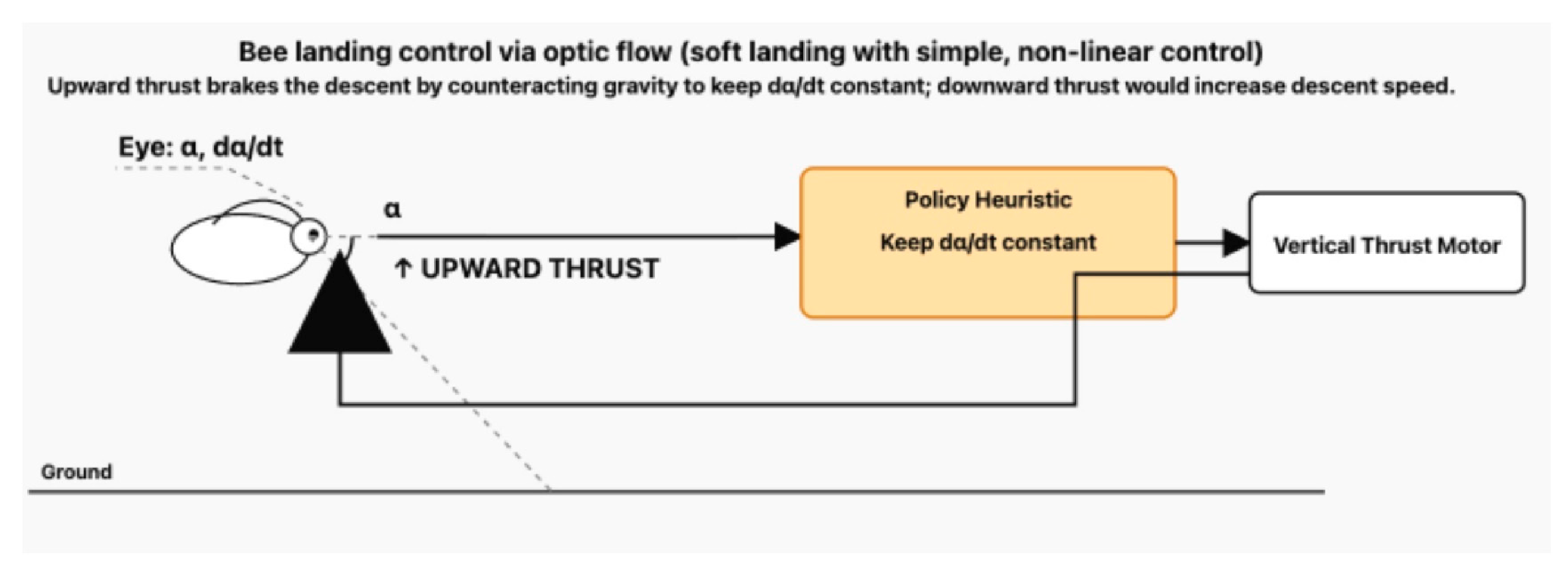
Figure 4.
Polarized-sky navigation as a low-bandwidth compass for the Policy Tier. UV photoreceptors in the dorsal rim area (DRA) of the compound eye detect the pattern of polarized skylight, whose e-vector orientation is fixed relative to the sun’s position [7]. Specialized neural circuits integrate this e-vector information to maintain a stable global heading even when the sun is obscured. This stable heading signal is fed into the central complex (Policy Tier), where it biases path integration and route selection. In our edge-AI analogy, the polarized-sky compass corresponds to a low-rate, robust global heading sensor that provides a cheap, reliable Policy input on top of faster Reflex loops.
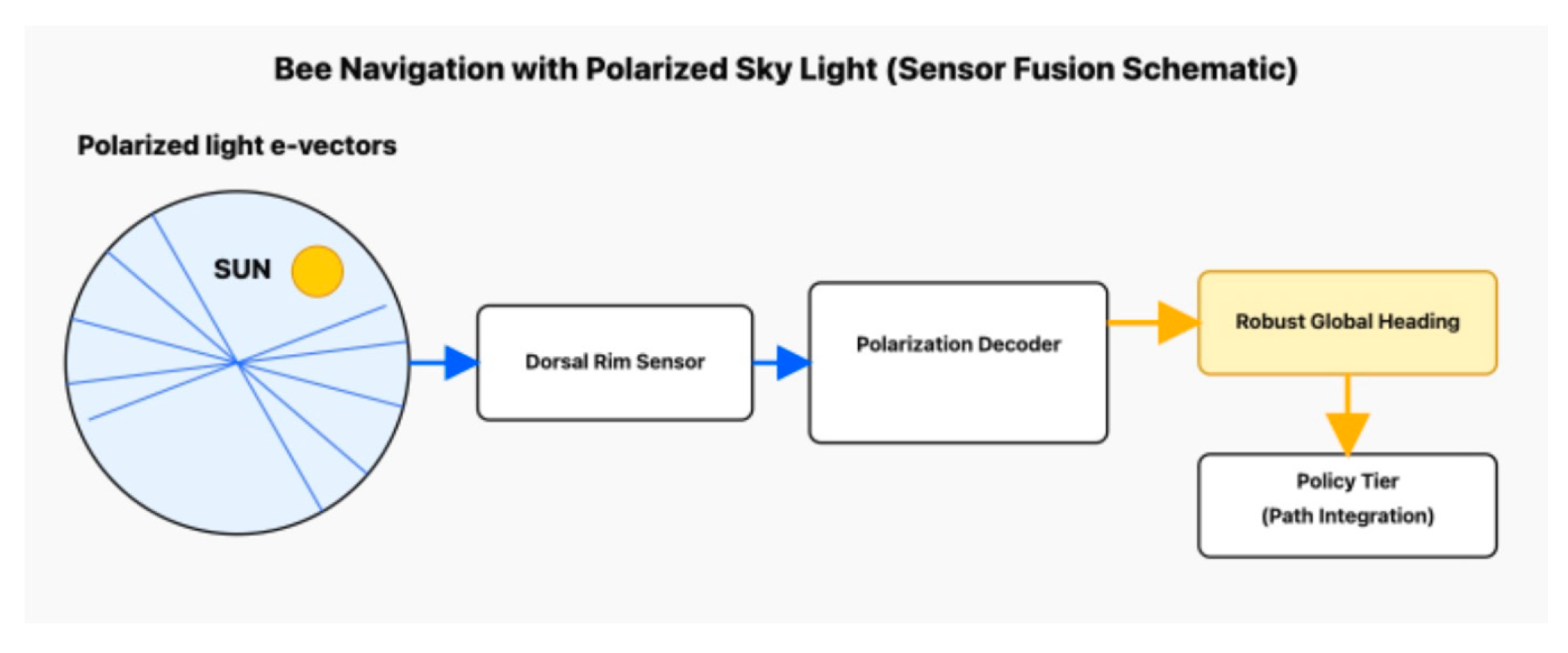
Figure 5.
Central-complex ring attractor: insect head-direction state for Policy. Visual and proprioceptive inputs (optic flow, haltere-like rotational cues, landmark signals) converge onto the central complex, where they drive a recurrent “ring attractor” network [8,9]. This circuit maintains a persistent bump of activity whose position encodes the animal’s current heading in allocentric space. The bump serves as a compact internal state variable, an internal compass, that biases downstream motor reflexes without changing their local structure. In our architecture this corresponds to a Policy-Tier state variable (heading set-point) that modulates Reflex Islands while preserving their timing and safety properties.
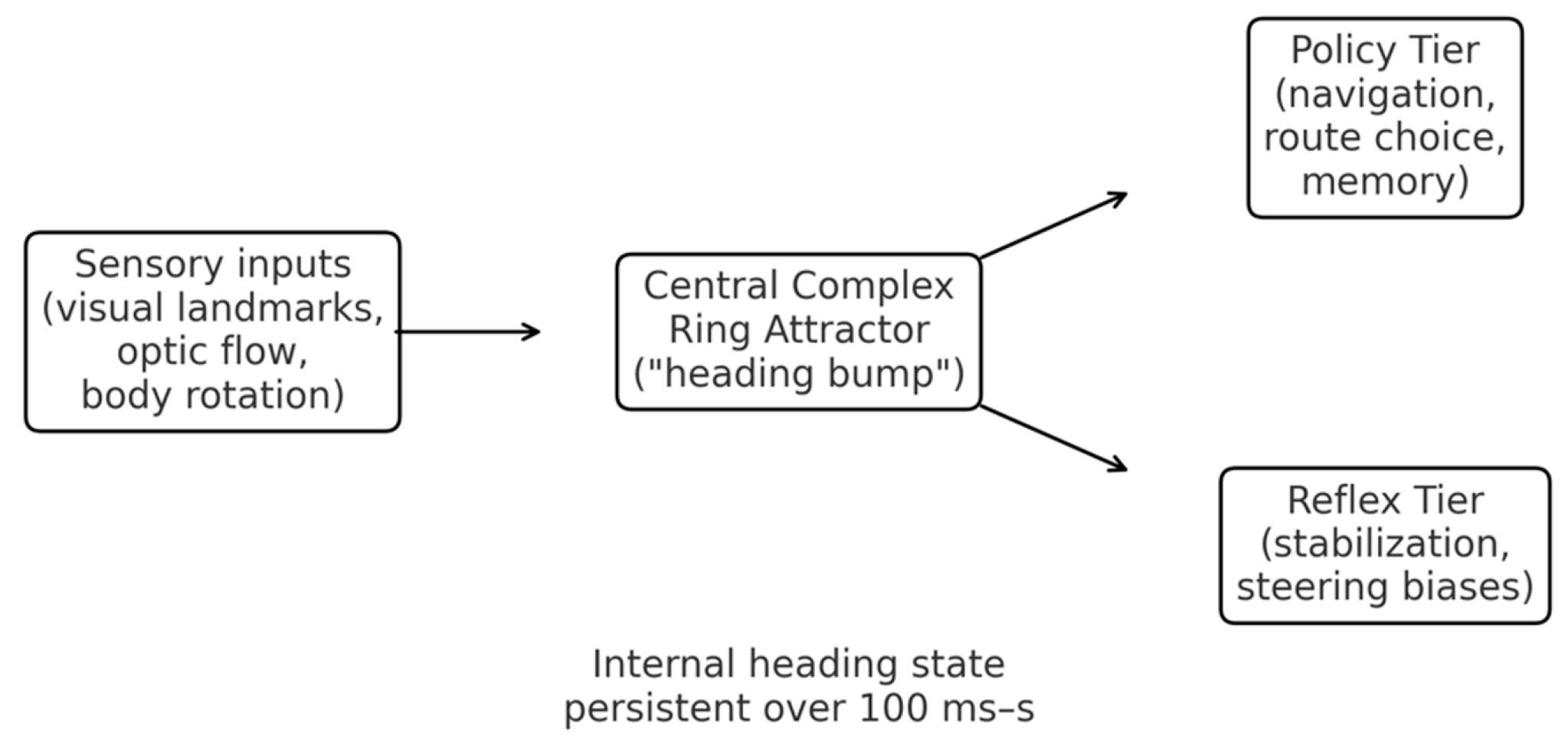
Figure 6.
A schematic illustrating how spintronic devices implement insect Edge AI principles. Spintronics for Bio-Inspired Edge AI. Spintronic Architecture for the Reflex Island [10,15,16]. .
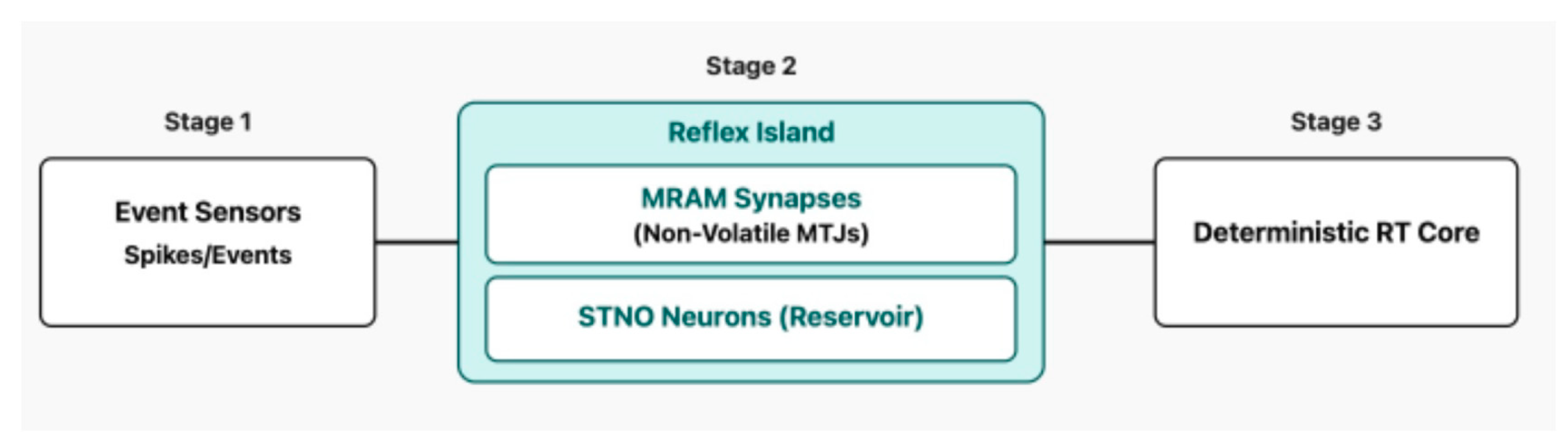
Figure 7.
Heat balance and size scaling for small flyers and edge hardware (conceptual). A lumped body of volume and surface receives internal power and loses heat via convection and radiation to ambient . Linearizing radiation around yields a combined cooling conductance and a first-order thermal time constant with . With and , one finds : smaller characteristic length → higher → larger per unit heat capacity → shorter . The mini-panels contrast large bodies (slow thermal response; wide passive buffer) with insect-scale bodies and dense edge-AI modules (fast thermal response; tight, actively managed thermal budgets).
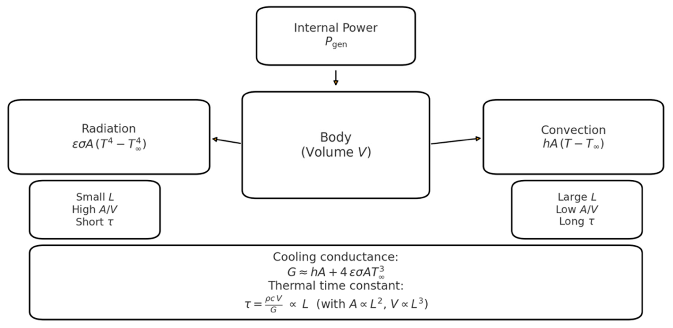
Figure 8.
Four-stroke “natural engine” view of insect thermoregulation and its edge-AI analogue. Top: conceptual mapping of insect thermal behaviour onto four logical strokes, REST/IDLE (low metabolism, spiracles mostly closed), WARM-UP (shivering raises thoracic temperature), WORK/BURST (flight; muscle power coupled to ventilation and evaporative cooling), and COOL-DOWN (post-flight heat export and return to baseline) [17,18,19,20,21,22,23,24]. Bottom: engineering analogy, where an Edge-AI platform uses the same four logical states to govern power and temperature: sensors measure on-die and ambient temperatures; a firmware thermal state machine adjusts DVFS, workload (Reflex vs Policy), and cooling to maintain a performance-optimal set-point while allowing short, bounded bursts of high performance without thermal runaway.
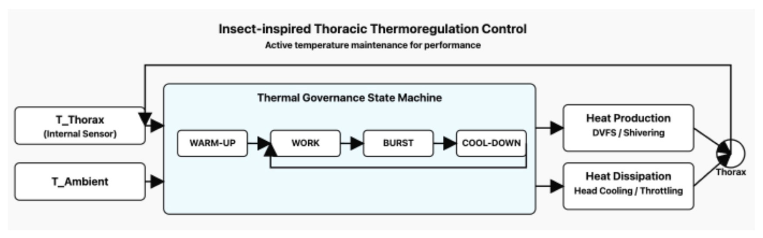
Figure 9.
Mechanical efficiency vs. normalized power for engines, miniturbines and insect flight muscle. Mechanical efficiency as a function of normalized mechanical power (fraction of rated power). The solid curve shows a schematic diesel/gasoline ICE map with a broad peak around 45% efficiency at ~0.75 of rated power and modest degradation at full load as in standard BSFC maps [36,37]. The dashed curve shows a schematic micro gas turbine/miniturbine map representative of 200–400 N units, with peak efficiency ≲25% near 0.8 of rated power and pronounced losses at partial load. The shaded band indicates the ~10–15% mechanical efficiency range reported for insect flight muscle over a wide operating range, and the coloured symbols illustrate representative efficiencies from classical studies by Weis-Fogh [52], Ellington [53], Harrison & Roberts [54], Josephson[70] and Marden[71]. The curves are intentionally schematic but capture the qualitative contrast between narrow, load-sensitive engine maps and the comparatively weak load dependence of insect flight muscle.
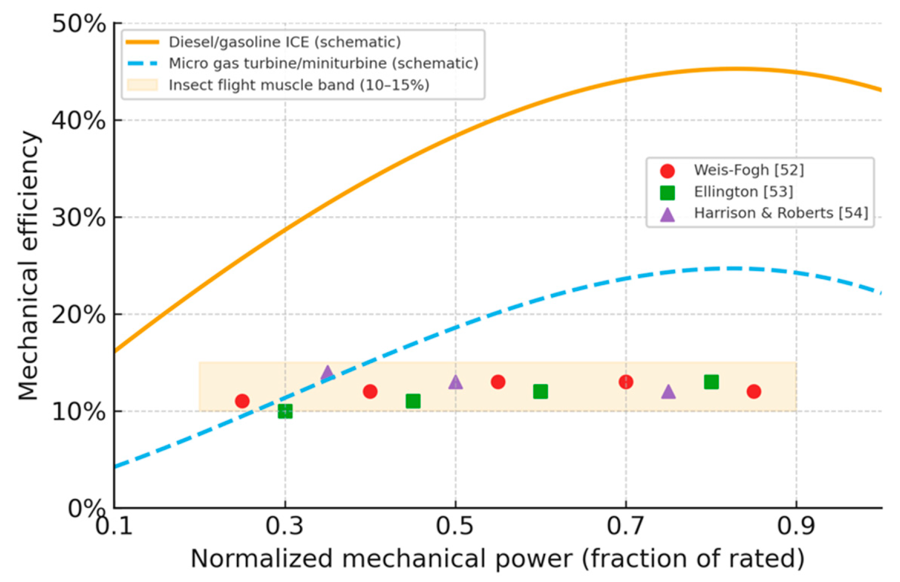
Figure 10.
Insect thermoregulation with in-flight modulation (A/B). (A) Full timeline from REST (cool) through WARM-UP (shivering) to FLIGHT, where a visible periodic modulation illustrates beat-synchronous thermal cycling (amplitude enlarged for clarity), followed by COOL-DOWN to repay thermal debt. (B) Zoom into two cycles, labeled Intake → Compression → Power → Exhaust to highlight the four-stroke-like modulation during steady flight. Real wingbeat oscillations occur at 10²–10³ Hz and are typically smaller; the schematic emphasizes the control concept supported by classic thermoregulation studies [21,22,23,24,32]. For example, resting bumblebees sit with body temperature close to ambient (often around 15–20 °C), but before take-off they rapidly warm their thoracic flight muscles by shivering, raising thorax temperature to at least ~30 °C and then regulating it around 35–40 °C during flight, largely independent of air temperature. This warm-up is accompanied by a jump in metabolic rate of one–two orders of magnitude relative to rest, as documented in Heinrich’s classic measurements of bumblebee thermoregulation and flight energetics [21,22].
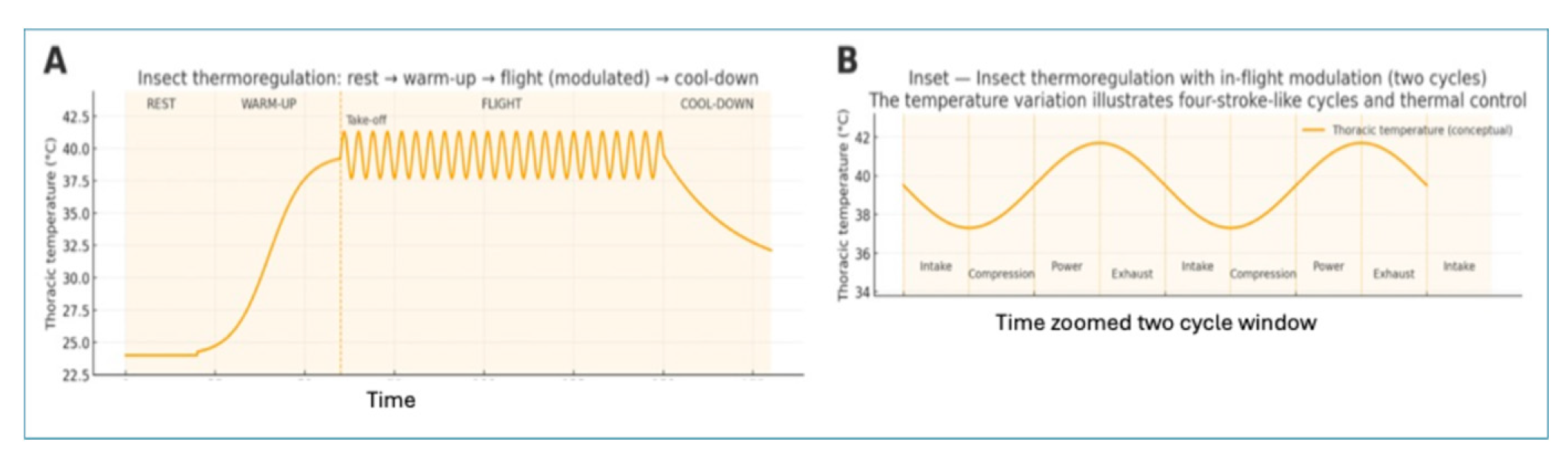
Figure 11.
The IFEVS thruster band on the schematic efficiency comparison of figure 9.
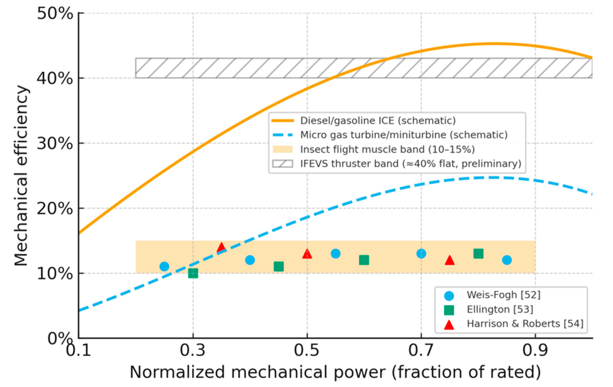
Disclaimer/Publisher’s Note: The statements, opinions and data contained in all publications are solely those of the individual author(s) and contributor(s) and not of MDPI and/or the editor(s). MDPI and/or the editor(s) disclaim responsibility for any injury to people or property resulting from any ideas, methods, instructions or products referred to in the content. |
© 2025 by the authors. Licensee MDPI, Basel, Switzerland. This article is an open access article distributed under the terms and conditions of the Creative Commons Attribution (CC BY) license (https://creativecommons.org/licenses/by/4.0/).
Copyright: This open access article is published under a Creative Commons CC BY 4.0 license, which permit the free download, distribution, and reuse, provided that the author and preprint are cited in any reuse.


