
Submitted:
17 November 2025
Posted:
18 November 2025
You are already at the latest version
Abstract
Recent advances in mobile robotics have emphasized the need for systems capable of 2 operating in unstructured environments, combining obstacle negotiation, stability, and 3 adaptability. This study presents a preliminary design of an articulated ground robot, 4 Brush.Q, equipped with compliant brush-like wheels composed of multiple spokes. The 5 wheels occupy the majority of the robot’s track width, minimizing chassis exposure to 6 obstacles, and integrate passive compliance along with a flexible articulated structure to 7 enhance obstacle-climbing and suspension capabilities. To evaluate these capabilities, a 8 prototype was tested across various terrains and obstacle heights, assessing the effects 9 of wheel rotation direction, spoke number, and spoke tapering. Experimental results 10 demonstrate that reducing the number of spokes improves obstacle-climbing capability, 11 while a higher number of spokes and compliant geometry enhance suspension and stability. 12 Tapered spokes can increase obstacle negotiation but reduce suspension performance. 13 These findings highlight the critical role of wheel geometry in wheel-legged robots and 14 suggest the potential for reconfigurable spoked wheels that enhance a robot’s adaptability 15 and versatility in unstructured environments.
Keywords:
wheel-legged robot
; spoke wheels
; compliant wheels
; articulated structure
; unstructured environment
; search and rescue
1. Introduction
In recent years, mobile robotics has advanced rapidly, driven by the demand for autonomous systems able to operate in complex and unstructured environments. Applications such as infrastructure inspection, surveillance, and search-and-rescue require robots capable of traversing uneven terrains while navigating obstacles and maintaining stability on irregular surfaces [1]. Traditional locomotion approaches are wheels, legs, and tracks and each present trade-offs: wheeled robots offer energy efficiency and mechanical simplicity but struggle with vertical obstacles; legged robots deliver superior adaptability but at the cost of increased complexity and energy consumption; tracked robots provide enhanced stability but often suffer from reduced maneuverability in confined spaces. To address these challenges, hybrid locomotion systems that combine different modalities have emerged. Among these, wheel-legged robots are particularly promising: they integrate wheel-like motion with leg mechanisms for enhanced obstacle negotiation. One of the reference point for this family of robots is RHex [2], a compliant legged hexapod robot known for its robust, highly mobile locomotion across rugged terrain using full-rotation leg-spokes. Within wheel-legged robotics, designs fall into two main categories [3]: non-transformable wheel, which maintain fixed geometry, and transformable wheel, which can reconfigure their structure depending on the terrain. Transformable wheel-legged robots, such as the OmniWheg [4], FUHAR [5] and TurboQuad [6] allow active adjustment of wheel-leg geometry to overcome obstacles. However, they often come at the cost of added mechanical complexity, weight, and control demands. In contrast, non-transformable wheel-leg designs can retain simplicity and reliability while also taking advantage of passive compliance. One example is Whegs [7], which stands for Wheel-Legs, representing a non-transformable wheel-leg hexapod robot inspired by cockroaches gait. The system features multiple compliant spokes that function as both propulsion and suspension elements, enabling adaptability to irregular terrain. Some wheel-legged robots also feature articulated body structures: certain designs use a body flexion joint to improve stability and obstacle-climbing capability [8]. However, such joints typically do not provide significant gains in maneuverability. A notable example is the Advanced Security Guard (ASGUARD) [9], which integrates a passive compliant spine to boost traction on uneven terrain but does not deliver enhanced agility. More recent locomotion strategies enhance adaptability to an unstructured environment with an articulated or continuum body structure such as the FRESE robot family [10]. Lizard [11] features a cable-driven origami flexible spine to improve turning and obstacle-climbing capabilities. Ai et al. [12] presented a soft robot with a pneumatically actuated flexible body and wheel-legs, capable of moving across diverse terrains and climbing steps.
Within this context, this study presents the preliminary design of an articulated ground robot equipped with compliant brush-like wheels composed of multiple spokes. A prototype was tested to evaluate its obstacle-climbing and suspension capabilities, and the results provide insights into the potential of lightweight, mechanically adaptive wheel-leg systems for mobile robots operating in unstructured and challenging environments.
2. Materials and Methods
2.1. Functional Design: Mechanical Architecture
Wheel-legged robots are typically based on an architecture consisting of a central body with wheels mounted on either side. The robot body is typically enclosed, pseudo-rectangular in shape, and houses the motors, transmission system, electronics, sensors, and battery. Moreover, its front and rear faces usually feature a semicircular geometry, allowing the robot to overcome discontinuities encountered between the two wheels. This configuration offers the advantages of protecting the internal components and allowing the robot to perform self-righting maneuvers. However, despite certain geometric precautions, there remains the possibility that centrally located obstacles may obstruct robot motion. In the proposed design, each wheel occupies the majority of the robot’s track width, thereby minimizing the exposure of the central chassis. As a result, obstacles encountered along the midline are more likely to be engaged by the wheels rather than impacting the body, reducing the risk of immobilization. This design choice therefore enhances obstacle-crossing capability and reduces failure cases associated with chassis-ground interference. Figure 1 illustrates the functional design of Brush.Q, a mobile robot equipped with brush-like compliant wheels and a flexible articulated structure to improve mobility and adaptability to complex and unstructured environments. The brush-like wheels (BW) consist of multiple spokes that exhibit passive compliance due to their geometric profile. These characteristics enhance the robot’s ability to adapt to uneven terrain and to overcome obstacles. Each brush wheel is driven by an integrated actuator (M), without the need for external transmission components, resulting in architecture more reliable, efficient and compact. The wheels have a transverse footprint, indicated as b in the Figure, which is significantly larger than the chassis width, indicated as a. The articulated structure connects the four modules of the robot, each equipped with two wheels, through a series of yaw (YJ) and pitch (PJ) joints, equipped with elastic elements (EE), which improve mobility and obstacle negotiation capabilities. The structure is underactuated and controlled by two actuators via a cable-driven system. The cables are anchored to the head (HM) and tail (TM) modules of the robot. The actuator (M) controls yaw joints via a pair of cables (YC), enabling steering, while the pitch actuator (M) controls the pitch joints (PJ) via the lift cable (PC) to raise the robot off the ground. The tail module also carries the payload (P), including the battery and onboard electronics, so that it remains grounded while the robot is lifted. The head module houses the vision system (C), which supports the execution of the robot’s tasks.
Brush-like wheels represent the primary element of adaptability of Brush.Q to unstructured environments, even more so than its articulated structure. They consist of multiple spokes evenly distributed around the rotation axis. The number of spokes directly influences ride smoothness: reducing the number of spokes increases vertical hub oscillations during transitions between spokes, whereas a larger number of spokes distributes contact with the terrain more evenly, improving stability [7]. In addition, spoke geometry and radial thickness affect both obstacle-climbing and suspension capabilities, the latter being defined as the ability to reduce chassis oscillations in the presence of terrain irregularities.
The wheel design is inspired by RHex [2], whose semicircular legs with a constant radius of curvature provide passive compliance essential for adaptation to uneven terrain and for reducing chassis oscillations Figure 2 (a). However, single-spoke designs have limitations: locomotion on flat surfaces can be less smooth, and vertical hub oscillations increase stress on components, reducing ride smoothness.
Both spoke shape and number strongly influence obstacle-climbing performance. Modeling studies in the literature [13] investigated spokes derived from the basic semicircular leg geometry, showing that certain profiles introduce a preferential direction for obstacle crossing, while reducing the number of spokes increases the maximum obstacle height that can be overcome. Although the analyzed leg geometry is not exactly C-shaped, the results indicate that both spoke shape and spoke count are key factors affecting locomotor capability.
RHex mitigates vertical oscillation effects through a tripod gait, in which at least three legs remain in contact with the ground at all times, ensuring static and dynamic stability, continuous traction, and uniform load distribution even on irregular terrain. Similar strategies are employed in Whegs [7], where tripod gait helps stabilize movement despite a reduced number of simultaneously active legs. In general, spoke compliance can further attenuate vertical hub motion.
In this study, the analysis is extended to an innovative brush-like wheel with a high number of semicircular spokes inspired by RHex legs, whose geometry also functions as an integrated suspension. Three variants are compared: a wheel with nine spokes Figure 2 (b), a wheel with three spokes Figure 2 (c), and a wheel with three tapered spokes Figure 2 (d), to evaluate both obstacle-climbing and suspension capabilities. The key geometric parameters of interest, which will be reported for the prototype, are: radius of curvature of the spoke , hub radius r, outer wheel radius R, spoke thickness s, , defined as the angular separation between spokes and ,defined as the central angle between the attachment points of the tapered blades on the hub. For the tapered blade, s varies along its length and depends on , the angle between the line from the wheel center to the blade tip and the point on the blade being considered. Notably, the hub has a non-reduced diameter such as RHex and equal to r, allowing integration of the motor within the wheel and enabling a compact design in which the wheels occupy the majority of the robot’s track width.
2.2. Prototyping
To evaluate the obstacle-climbing and suspension capabilities of the different wheel types, a prototype was built, whose schematic design is shown in Figure 3. The prototype measures 204 mm in length (along the y-axis), 135 mm in width (along the x-axis), and 137 mm in height (along the z-axis).
The prototype consists of two modules rigidly connected to each other, each equipped with two brush wheels (BW). Each of the four wheels is actuated by its own gearmotor (G): a 163-RPM Mini Econ Gear Motor for the wheels of the head module (1), and an 81-RPM Mini Econ Gear Motor for those of the tail module (2). The wheels are driven by the gear motors through a two-stage spur gear transmission (GT) with a unit transmission ratio, chosen to preserve the output torque of the gear motor while avoiding excessive radial encumbrance of the gears. Each wheel is mounted via an interference fit onto its hub (H), which is manufactured as a single part with the spur gear which is coaxial with the wheel. The hub rotates freely with respect to an aluminum tube (T), clamped to the robot frame (F), thanks to a pair of plain bearings (BU). The axial positioning of the wheel is ensured by an end cap (EC), inserted into the tube through an interference fit. The transverse width of the wheels, 2b, is 98 mm, corresponding to 76% of the robot track width (2b+a). The battery (B), rated at 12 V, is located on the head module. The tail module hosts the robot control electronics: the switch (S) required to power the robot, the microcontroller unit (CU, Teensy 4.1) that controls the two dual-motor drivers (MD, TB6612FNG) regulating the input power to the gearmotors, and the inertial measurement unit (IMU, GY-521) used to measure the robot’s linear accelerations and angular velocities. The reference frame used for evaluating vertical acceleration is also indicated for the IMU. The robot frame, the gears, and the end caps were 3D-printed in Tough PolyLactic Acid (Tough PLA), while the brush wheels were fabricated in Thermoplastic Polyurethane (TPU) 82A. Figure 4 shows the four types of wheels that were manufactured: the circular wheel, chosen as the reference conventional wheel, the 9-spoke wheel, the 3-spoke wheel, and the tapered 3-spoke wheel. All wheels have an outer radius mm. The spoked wheels share a common hub radius mm. The 9-spoke (°) and 3-spoke (°) wheels feature the same spoke thickness mm, whereas the tapered 3-spoke version is manufactured with a tapering angle (°). Wheel replacement does not require disassembling the entire axle, as the wheels can be easiliy slid off the hub.
2.3. Experimental Tests
The experimental tests aimed to evaluate the suspension and obstacle-climbing capabilities of the different wheels considered. Three parameters were analyzed as potentially affecting the wheel behavior:
- The number of spokes;
- The wheel rotation direction;
- The cross-sectional profile of the spoke along the radial direction.
The combination of these parameters results in a set of configurations summarized in Table 1. The designation of each configuration, except for the conventional circular wheel, indicates the number of spokes (zero for the circular wheel configuration) and the direction of motion, which refers to the orientation of the C-shaped spokes. Specifically, when the first contact point with the ground lies on the upper surface of the spoke, the configuration is referred to as forward-facing (FF), whereas when the first contact point coincides with the spoke tip, it is referred to as backward-facing (BF). The variation of the spoke thickness was analyzed only for the 3-spoke wheel configuration.
2.3.1. Obstacle-Climbing Capability
The obstacle-surmounting capability refers to a robot’s ability to overcome obstacles with heights greater than its wheel radius, heights that a conventional wheel would normally be unable to handle. To experimentally evaluate the obstacle-climbing capability of the different wheels, a test setup was constructed using rectangular obstacles of varying heights (Figure 5). Each obstacle was created by stacking a series of wooden boards fixed to the surface of a table. The heights tested were 16 mm (0.53R), 33 mm (1.1R), 47 mm (1.57R), and 51 mm (1.7R), where R is the wheel radius and is 30 mm.
The experiments evaluated the climbing ability of the circular wheel and the spoked wheels in different configurations. Each configuration was defined by a specific number of spokes and a rotation direction. For each configuration, five trials of up to 10 seconds were performed. A trial was considered successful if the robot neither tipped over nor became stuck, and if all four wheels rested stably on top of the obstacle. Trials were excluded from the evaluation if the wheel hub became lodged beneath the top board of the obstacle, as this outcome was influenced by the arbitrary initial angular position.
The robot was tested starting from rest at an initial distance of 10 cm from the obstacle. Before activation, the robot’s wheels were synchronized at arbitrary angular positions relative to each other to minimize the risk of lateral tipping, which occurs when the robot encounters an obstacle with only one wheel. This effect is more pronounced for wheels with fewer spokes, as the contact between the wheel and the ground is more discontinuous. The robot was operated in open-loop velocity control at an input of 81 rpm. After the the acceleration transient and just before the obstacle, it reached a speed of approximately 2.5 cm/s.
To evaluate the experimental influence of the wheels alone, it was important to minimize the frontal surface of the obstacle in order to reduce the effect of rear-wheel traction, which can push the front wheels against a vertical obstacle and facilitate climbing even if the wheels are not geometrically suited.
2.3.2. Suspension Capability
The suspension capability of a robot is generally defined as its ability to reduce chassis oscillations caused by terrain irregularities, maintain wheel ground contact to ensure traction and stability, and absorb shocks by attenuating the impact forces transmitted to the chassis and internal components. In this study, we focus on a specific aspect of this capability: the analysis of high-frequency vibrations arising from wheel ground interactions while traversing obstacles smaller than the wheel radius. Although these vibrations occur at frequencies higher than the primary chassis oscillations, they play a crucial role in assessing the robot’s structural response and the durability of components.
To assess the suspension capability of the wheels, time-domain vertical acceleration signals ( see the IMU reference frame indicated in Figure 3) were acquired using the IMU sensor with a sampling frequency of 260 Hz and a full scale range of (where g is the gravitational acceleration 9.81 ) and then logged on a SD card. The robot was tested on two types of terrain: a regular surface, the tiled floor (Figure 6 (a)), used as a reference, and an irregular surface, cobblestones (Figure 6 (b)). Five trials were conducted for each wheel configuration on both terrains, with each trial lasting 10 seconds. The robot was placed in a sufficiently flat area and was operated in open-loop velocity control. In this case as well, before each trial the wheels were synchronized to an arbitrary angular position.
The data were then processed to obtain a representative frequency spectrum for the different cases. For each terrain and configuration, five signals were acquired. The signal were aligned signals, superimposed and averaged point by point, obtaining a statistically representative signal for each configuration and terrain.
Subsequently, the Fast Fourier transform (FFT) of the averaged signals was computed and normalized by the number of samples (N). The FFT is an algorithm that computes the discrete Fourier Transform (DFT) of a sequence (reference). To compare different configurations on the same terrain, each spectrum was truncated at a common maximum frequency of Hz, corresponding to the minimum Nyquist frequency among all the averaged signals of the various configurations (for the mathematical derivations, see Appendix A. A qualitative frequency-domain analysis of the vertical acceleration signals was therefore carried out by varying one parameter at a time while keeping the others fixed.
To assess the suspension effect of the wheels under the various configurations, the high-frequency components of the acceleration signals were analyzed based on a fixed frequency threshold, common to all configurations and to both terrains. This threshold was not derived from literature values but was pragmatically defined to qualitatively separate the low-frequency components — corresponding to the theoretical rotation frequency (1.33 Hz) and the spoke-passing frequencies (Hz for the 3-spoke wheel and 11.97 Hz for the 9-spoke wheel) — from the faster oscillations associated with the suspension system dynamics. Although this approach is qualitative, it enables a coherent and meaningful comparison among the different wheel configurations for each terrain. The threshold separating low and high frequency components was set at 30 Hz, a value higher than two times the maximum blade-passing frequency (11.97 Hz). In this way, the components above this threshold represent the dynamic behavior of the wheels and the suspension capability of the system.
3. Results and Discussion
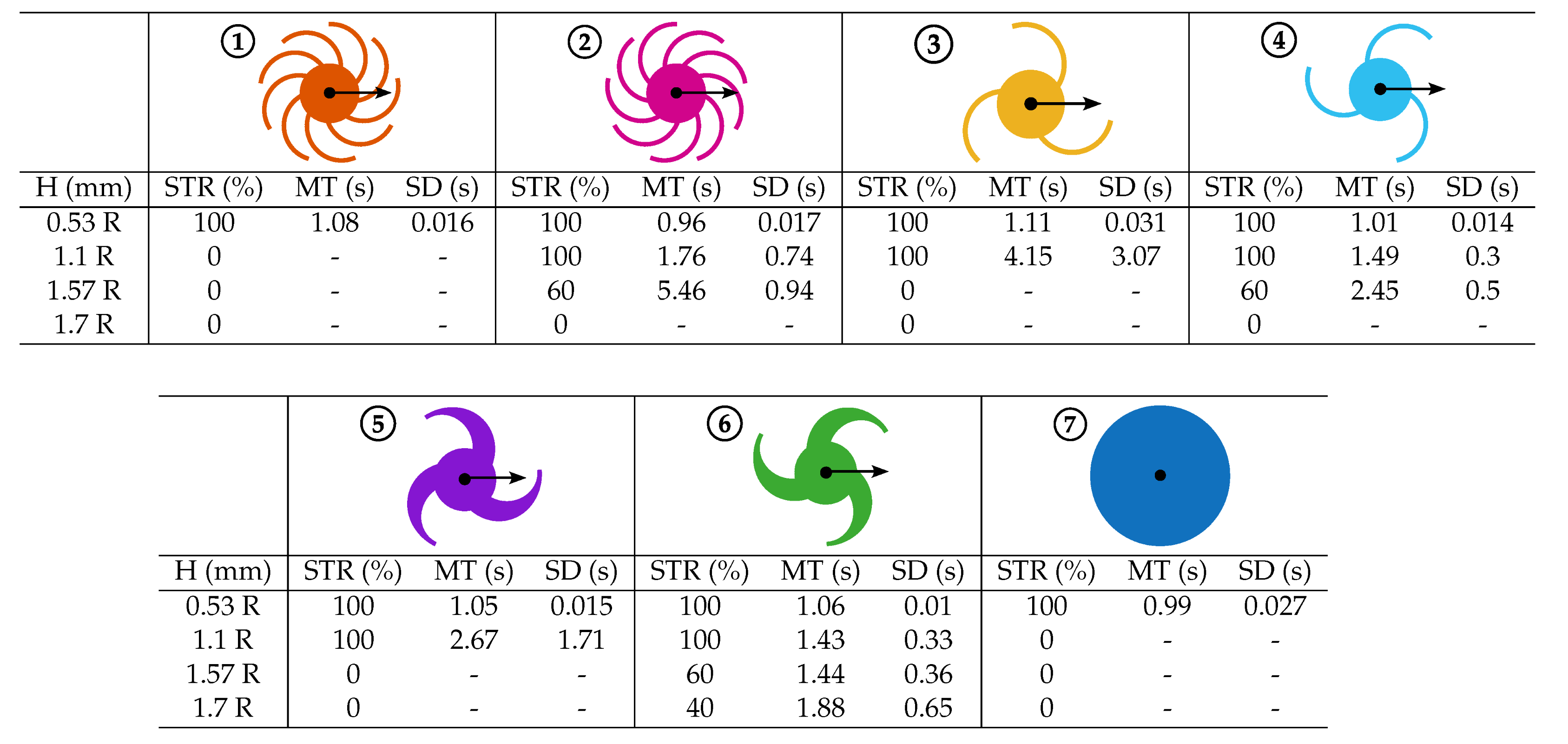
Table 2 reports the experimental results related to obstacle-climbing capability: the successful trial rate (STR) for the five trials conducted at the different obstacle heights H, expressed as a scaled value of the wheel radius for each configuration. To allow comparison between configurations with the same STR, both the mean time (MT) and the corresponding standard deviation (SD) are reported. MT is defined as the interval between the moment the front wheels approach the obstacle and the moment all wheels are stably on top of it. In practice, a configuration better suited for obstacle-climbing requires less time, as it relies primarily on shape-based coupling, determined by wheel geometry, rather than force-based interaction with the obstacle’s frontal surface. This behavior is due to the flexibility of the spokes, which deform upon frontal contact with the obstacle, facilitating the engagement of the subsequent spoke. Furthermore, as noted above, a higher number of spokes improves frontal grip, particularly for the leading module, which benefits from the push of the following module to increase deformation, contact force, and thus traction on the frontal surface.
From the experimental data of obstacle-climbing capability of the different wheel configurations, the following conclusions can be drawn:
- Circular wheel behaviour: The circular wheel (7) can overcome only the smallest obstacle, with a height of 0.53R.
- Effect of wheel rotation direction: Regardless of the number of spokes, the backward-facing configurations (2), (4), and (6) outperform the corresponding forward-facing configurations (1), (3), and (5) in terms of both success rate and traversal time. This is attributed to favorable shape-based engagement and reduced interference with the obstacle.
- Influence of the number of spokes: Configurations with 3 spokes, both forward-facing (3, 5) and backward-facing (4, 6), generally outperform the corresponding 9-spoke configurations. The lower number of spokes enables these wheels to overcome taller obstacles. Moreover, even when the successful trial rate (STR) is equal, as observed for configurations (2), (4), and (6) at a height of 1.7R, the mean traversal time (MT) consistently favors the 3-spoke configurations (Figure 7 (a-b)).
- Effect of spoke stiffness: For a given number of spokes, tapering the spokes to increase stiffness allows the wheel to overcome higher obstacles. With the same robot weight, stiffer spokes raise the wheel height above the ground, allowing the wheel to surmount taller obstacles (Figure 7 (c)). At the same time, the increased stiffness limits the bending of the spoke during contact with the obstacle, thereby facilitating its traversal.
- Stability considerations: Although 3-spoke configurations achieve higher obstacle-climbing capability, they are also more unstable: with 3 spokes, there are fewer simultaneous contact points and a lower contact frequency with the ground, causing the body to oscillate more and increasing the risk of tipping. With 9 spokes, the greater number of distributed contacts maintains robot stability even if some spokes are not perfectly synchronized. Therefore, at equal angular velocity, loss of angular synchronization between the wheels increases the likelihood of lateral tipping. (Figure 8).
Figure 9 (a–e) show comparisons of the frequency spectra for the various configurations, while Figure 9 (f–g) present the time-domain acceleration signals and frequency spectra of the most significant configurations on the tiled floor.
Figure 10 (a–e) show comparisons of the frequency spectra for the various configurations, while Figure 10 (f–g) show the time-domain acceleration signals and frequency spectra of the most significant configurations on the cobblestone.
From the experimental data of suspension capability of the different wheel configurations, the following qualitative conclusions can be drawn:
- Tiled floor: The circular wheel, together with the 9-spoke forward-facing wheel, exhibits the best suspension capability, with the latter being slightly superior (Figure 9 (a) and Figure 9 (g)). The wheel rotation direction does not appear nto be a significant parameter (Figure 9 (a) and Figure 9 (b)), except for the tapered 3-spoke wheel (Figure 9 (c)), where the forward-facing configuration appears to yield worse results, e.g., it exhibits higher vibration levels at higher frequencies. The number of spokes highlights an advantage for the 9-spoke wheel (Figure 9 (d)) because the contact with the ground is more continuous. The tapering of the 3-spoke wheel further reduces suspension capability due to the increased stiffness (Figure 9 (e)). In summary, the circular wheel and the 9-spoke forward-facing wheel are the best-performing configurations, whereas the tapered 3-spoke wheel is the worst-performing one, as indicated by the acceleration peaks in (Figure 9 (f)).
- Cobblestones: On this terrain, the circular wheel performs the worst (Figure 10 (a) and Figure 10 (g)) because its shape does not adapt well to irregularities. The 9-spoke wheel, on the other hand, maintains consistently good capabilities (Figure 10 (a) and Figure 10 (f)). Wheel rotation direction has little impact overall, except for a slight degradation in the forward-facing configurations of the 3- and 9-spoke wheels (Figure 10 (a) and Figure 10 (b)), which becomes more noticeable for the tapered 3-spoke wheel (Figure 10 (c)). Regarding the number of spokes, 3-spoke wheels show reduced capability (Figure 10 (d)), with further degradation for the tapered profile (Figure 10 (e)). In summary, the 9-spoke forward-facing wheel is the best-performing configuration, while the circular wheel and the tapered 3-spoke wheel are the worst, as shown by the acceleration peaks in Figure 10 (f).
The Table 3 provides a qualitative overview of the obstacle-overcoming and suspension capabilities associated with each wheel configuration. The experimental campaign highlights the following key outcomes:
- The circular wheel consistently exhibits the lowest capabilities, confirming its limited suitability for operation on unstructured or irregular terrains;
- The wheel rotation direction has a measurable impact on both capabilities, with a clear improvement when transitioning from the forward-facing to the backward-facing configuration;
- A reduction in the number of spokes leads to a degradation in suspension capability, while concurrently enhancing obstacle-climbing capability, independently of the rotation direction;
- A variation in the spoke thickness, considered in this context as a tapering of the spoke profile, does not affect the obstacle-climbing capability in the forward-facing configuration, while it leads to a noticeable improvement in the backward-facing configuration. However, profile tapering consistently reduces the suspension capability for both rotation directions.
Overall, the findings indicate that all three design parameters, wheel rotation direction, number of spokes, and spoke tapering, significantly influence wheel behavior. While rotation direction strongly affects obstacle-climbing, it requires repositioning the robot, which may not be feasible in constrained environments. In contrast, modifying the number of spokes or the spoke tapering can achieve substantial improvements in both obstacle traversal and suspension without moving the robot. This highlights the potential for a reconfigurable spoked wheel design that enhances adaptability and versatility in unstructured terrains while minimizing operational constraints.

Table 3.
Qualitative assessment of different wheel configuration capabilities.
4. Conclusions
This study investigated the preliminary design and testing of an articulated ground mobile robot equipped with compliant brush-like wheels, which are spoked wheels with passive compliance. Each wheel occupies the majority of the robot’s track width, reducing the exposure of the central chassis to obstacles and improving obstacle-climbing performance. A prototype was built to assess the obstacle-climbing and suspension capabilities of three wheel variants: a 9-spoke wheel, a 3-spoke wheel, and a tapered 3-spoke wheel. The results demonstrate that wheel geometry critically affects the robot’s capabilities: reducing the number of spokes increases the maximum obstacle height that can be overcome, while a higher spoke count and compliant geometry improve suspension and stability on uneven terrain. Tapered spokes can further enhance obstacle negotiation but may reduce suspension effectiveness. Wheel rotation direction also influences both capabilities, although modifying spoke geometry provides a more practical strategy to enhance adaptability without the need to reposition the robot, which is particularly advantageous in narrow or confined spaces typical of unstructured environments.
Author Contributions
Conceptualization, L.T. and G.Q.; methodology, L.T., A.B., G.C.and L.T.; software, L.T., A.B., G.C.and L.T.; validation, L.T., A.B., G.C. and L.T.; formal analysis, L.T., A.B., G.C. and L.T.; investigation, L.T., A.B., G.C.and L.T.; resources, L.T., A.B., G.C. and L.T.; data curation, L.T., A.B., G.C.and L.T.; writing—original draft preparation, L.T., A.B., G.C., L.T., C.V. and G.Q.; writing—review and editing, L.T., A.B., G.C., L.T., C.V. and G.Q.; visualization, L.T., A.B., G.C., L.T., C.V and G.Q.; supervision, C.V. and G.Q.; project administration, C.V. and G.Q.; funding acquisition, C.V. and G.Q. All authors have read and agreed to the published version of the manuscript.
Funding
This research received no external funding.
Data Availability Statement
The original contributions presented in the study are included in the article. Further inquiries can be directed to the corresponding authors.
Conflicts of Interest
The authors declare no conflicts of interest.
Appendix A. Data Processing and Spectral Analysis Method
The processing of the acceleration data can be summarized as follows.
Let denote the vertical acceleration signal acquired during the i-th trial, sampled with an average sampling frequency . Since the sampling frequencies slightly differed among tests, a common sampling frequency was selected as
to avoid loss of information. A common time grid was then defined as
and each signal was linearly interpolated on this grid:
The averaged acceleration signal, representative of each configuration, was obtained as
where is the number of trials.
The discrete Fourier transform (FFT) of the averaged signal was computed as
where N is the total number of samples. The magnitude spectrum was therefore expressed as
Since the signals corresponding to different configurations had slightly different Nyquist frequencies
all spectra were truncated to a common maximum frequency:
ensuring direct comparability across configurations.
To distinguish the slow cyclic components (wheel rotation and spoke passage) from the fast oscillations related to the suspension dynamics, the frequency domain was qualitatively divided into two regions:
where the threshold frequency was set to
more than two times the maximum spoke-passing frequency (11.97 Hz). Thus, frequencies above represent the wheel dynamic behavior and the suspension system’s capability to attenuate vibrations.
References
- Bruzzone, L.; Quaglia, G. Review article: Locomotion systems for ground mobile robots in unstructured environments. Mechanical Sciences 2012, 3, 49–62. [Google Scholar] [CrossRef]
- Moore, E.Z.; Campbell, D.; Grimminger, F.; Buehler, M. Reliable stair climbing in the simple hexapod ’RHex’. In Proceedings 2002 IEEE International Conference on Robotics and Automation (Cat. No.02CH37292); IEEE: Washington, DC, USA, 2002; pp. 2222–2227. [Google Scholar] [CrossRef]
- Park, I.; Yoon, H.; Kim, S.; Kim, H.S.; Seo, T. Review on Transformable Wheel: Mechanism Classification and Analysis According to Mechanical Complexity. International Journal of Precision Engineering and Manufacturing 2025, 26, 737–755. [Google Scholar] [CrossRef]
- Cao, R.; Gu, J.; Yu, C.; Rosendo, A. OmniWheg: An Omnidirectional Wheel-Leg Transformable Robot. In 2022 IEEE/RSJ International Conference on Intelligent Robots and Systems (IROS); IEEE: Kyoto, Japan, 2022; pp. 5626–5631. [Google Scholar] [CrossRef]
- Mertyüz, İ.; Tanyıldızı, A.K.; Taşar, B.; Tatar, A.B.; Yakut, O. FUHAR: A Transformable Wheel-Legged Hybrid Mobile Robot. Robotics and Autonomous Systems 2020, 133, 103627. [Google Scholar] [CrossRef]
- Chen, W.-H.; Lin, H.-S.; Lin, Y.-M.; Lin, P.-C. TurboQuad: A Novel Leg–Wheel Transformable Robot With Smooth and Fast Behavioral Transitions. IEEE Transactions on Robotics 2017, 33, 1025–1040. [Google Scholar] [CrossRef]
- Quinn, R.D.; Offi, J.T.; Kingsley, D.A.; Ritzmann, R.E. Improved mobility through abstracted biological principles. In IEEE/RSJ International Conference on Intelligent Robots and Systems; IEEE: Lausanne, Switzerland, 2002; pp. 2652–2657. [Google Scholar] [CrossRef]
- Allen, T.J.; Quinn, R.D.; Bachmann, R.J.; Ritzmann, R.E. Abstracted Biological Principles Applied with Reduced Actuation Improve Mobility of Legged Vehicles. In Proceedings of the 2003 IEEE/RSJ International Conference on Intelligent Robots and Systems (IROS 2003) (Cat. No. 03CH37453); IEEE: Las Vegas, NV, USA, 2003; Volume 2, pp. 1370–1375. [Google Scholar] [CrossRef]
- Eich, M.; Grimminger, F.; Kirchner, F. A Versatile Stair-Climbing Robot for Search and Rescue Applications. In 2008 IEEE International Workshop on Safety, Security and Rescue Robotics; IEEE: Tokyo, Japan, 2008; pp. 35–40. [Google Scholar]
- Siles, I.; Walker, I.D. Continuum Robotic Elements for Enabling Negotiation of Uneven Terrain in Unstructured Environments. WSEAS Trans. Appl. Theor. Mech. 2013, 8. [Google Scholar]
- Jones, T.V.; Conard, G.G.; Sanchez, A.G.; Sun, Y.; Onal, C.D. Lizard: A Novel Origami Continuum Mobile Robot for Complex and Unstructured Environments. Robotics Reports 2025, 3, 1–11. [Google Scholar] [CrossRef]
- Ai, X.; Yue, H.; Wang, W.D. Crawling Soft Robot Exploiting Wheel-Legs and Multimodal Locomotion for High Terrestrial Maneuverability. IEEE Transactions on Robotics 2023, 39, 4230–4239. [Google Scholar] [CrossRef]
- Li, J.; Liu, Y.; Yu, Z.; Guan, Y.; Zhao, Y.; Zhuang, Z.; Sun, T. Design, Analysis, and Experiment of a Wheel-Legged Mobile Robot. Applied Sciences 2023, 13, 9936. [Google Scholar] [CrossRef]
Figure 1.
Functional design of Brush.Q: top view (a) and lateral view (b).
Figure 2.
Brush-like wheel design: (a) RHEx C-leg wheel. (b) 9-spoke wheel. (c) 3-spoke wheel. (d) Tapered 3-spoke wheel.
Figure 2.
Brush-like wheel design: (a) RHEx C-leg wheel. (b) 9-spoke wheel. (c) 3-spoke wheel. (d) Tapered 3-spoke wheel.
Figure 3.
The components of the prototype: (a) Isometric view. (b) Frontal view (x-z plane). (c) Lateral view of the head module (y-z plane): detail of the wheel-chassis coupling.
Figure 3.
The components of the prototype: (a) Isometric view. (b) Frontal view (x-z plane). (c) Lateral view of the head module (y-z plane): detail of the wheel-chassis coupling.
Figure 4.
The different types of wheels (in orange) fitted in the hub (in black): (a) circular wheel. (b) 9-spoke wheel. (c) 3-spoke wheel. (d) Tapered 3-spoke wheel.
Figure 4.
The different types of wheels (in orange) fitted in the hub (in black): (a) circular wheel. (b) 9-spoke wheel. (c) 3-spoke wheel. (d) Tapered 3-spoke wheel.
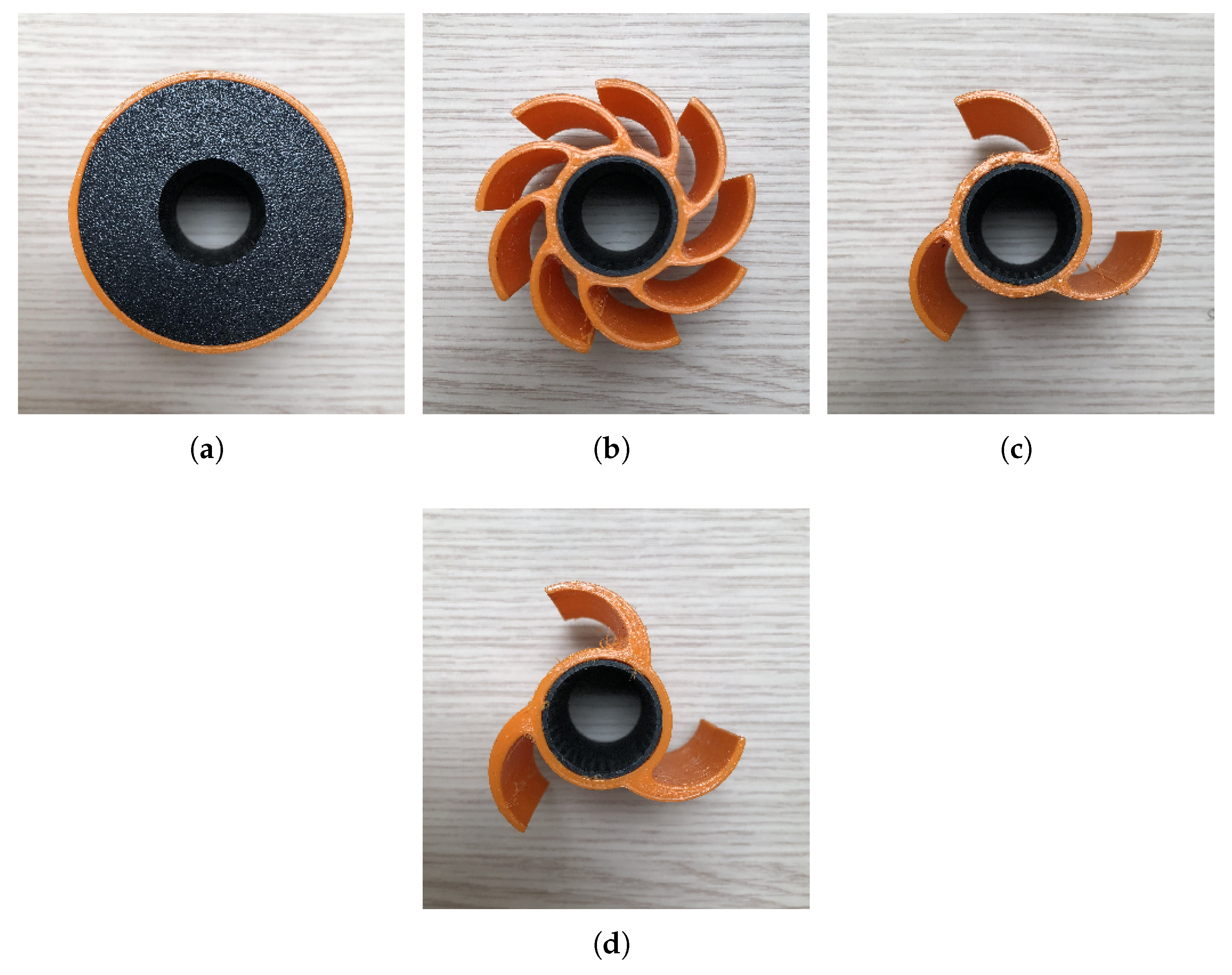
Figure 5.
Experimental setup for obstacle-climbing tests.
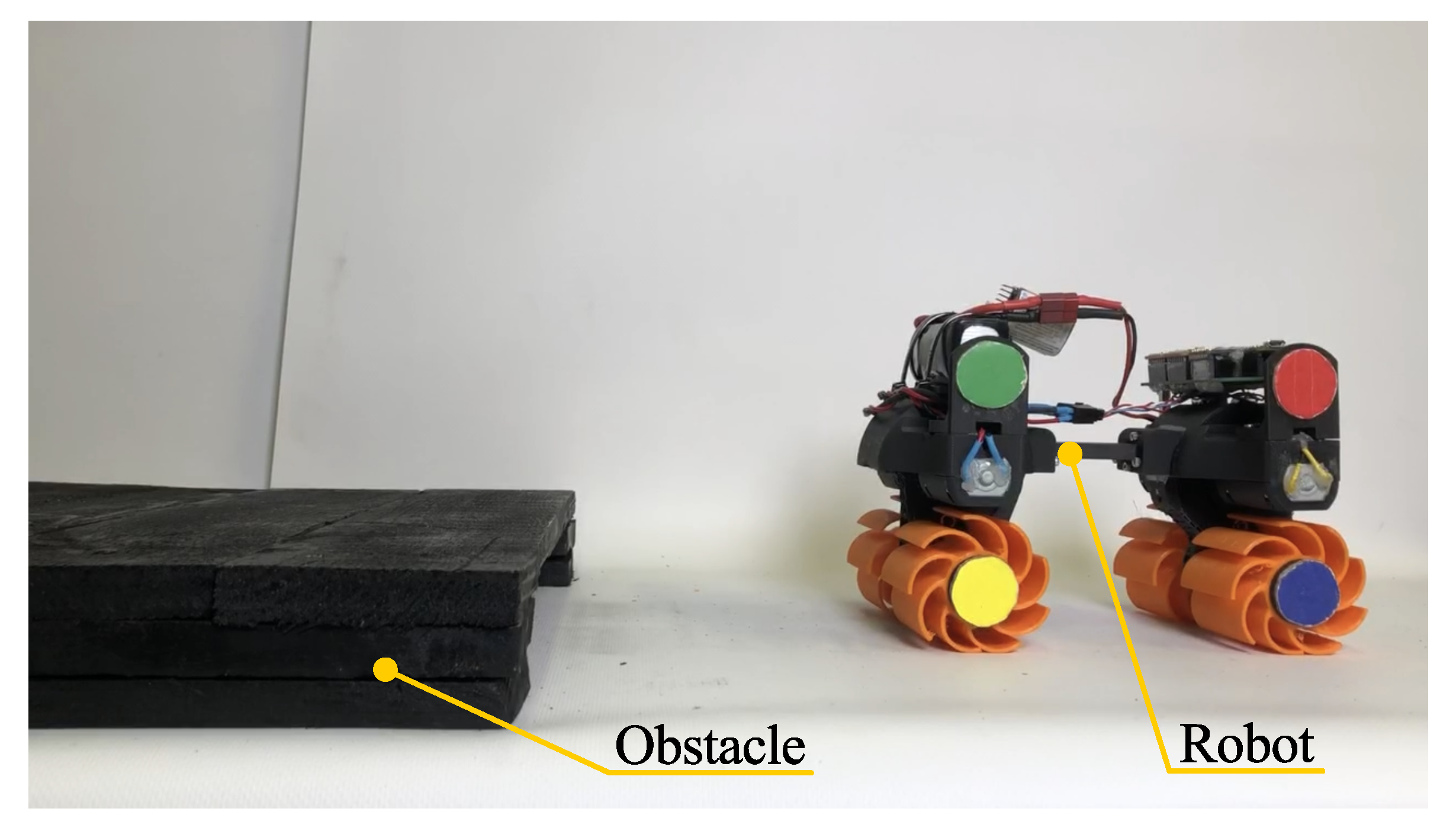
Figure 6.
The robot during the tests on: (a) Tiled floor. (b) Cobblestones.
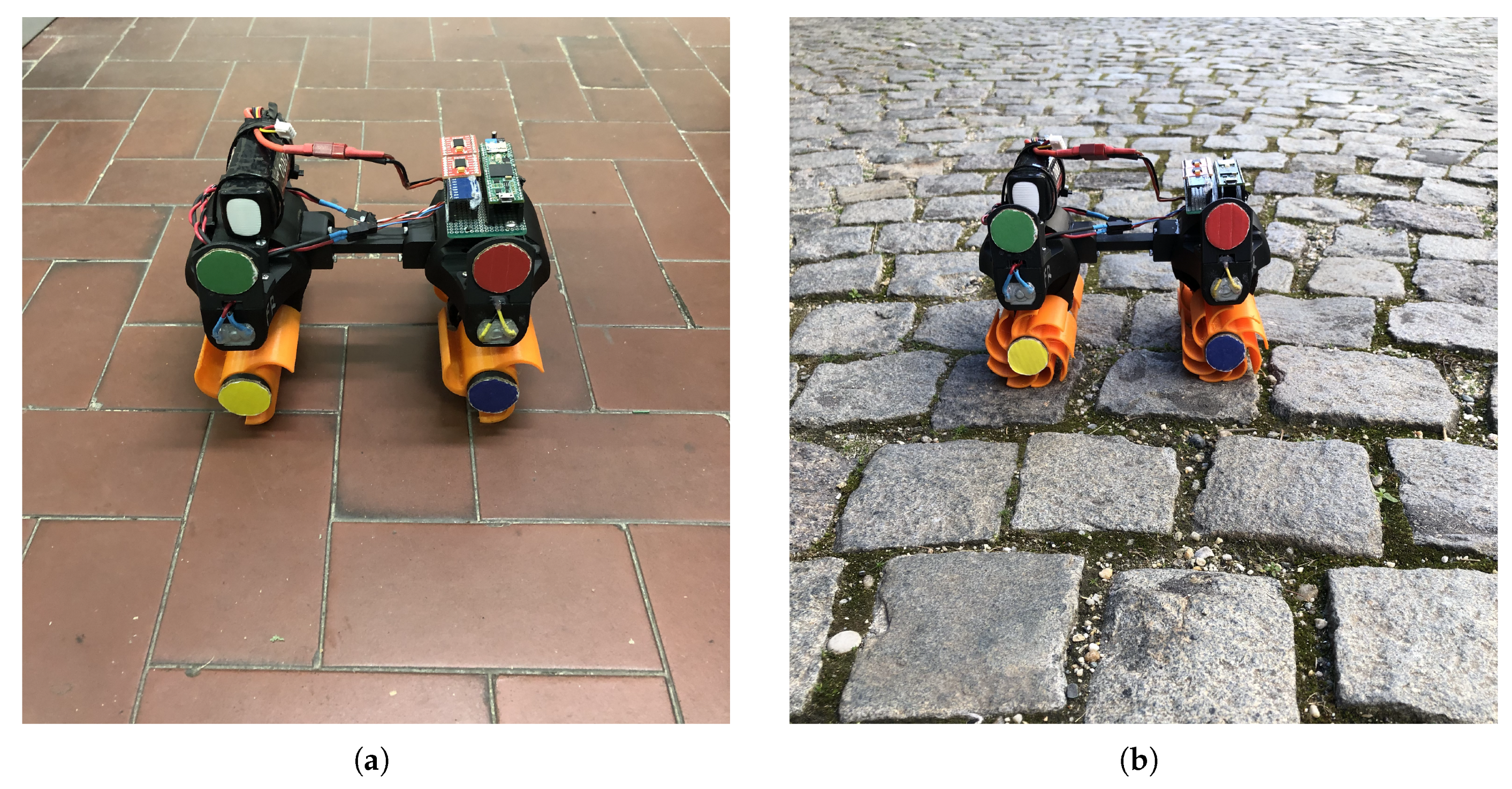
Figure 7.
A demonstration of the robot climbing obstacle with different wheel configurations at their maximum surmountable obstacle height: (a) 9-spoke wheel at a height of mm. (b) 3-spoke wheel at a height of H=1.57R (47 mm). (c) Tapered 3-spoke wheel at a height of H=1.7R (51 mm).
Figure 7.
A demonstration of the robot climbing obstacle with different wheel configurations at their maximum surmountable obstacle height: (a) 9-spoke wheel at a height of mm. (b) 3-spoke wheel at a height of H=1.57R (47 mm). (c) Tapered 3-spoke wheel at a height of H=1.7R (51 mm).
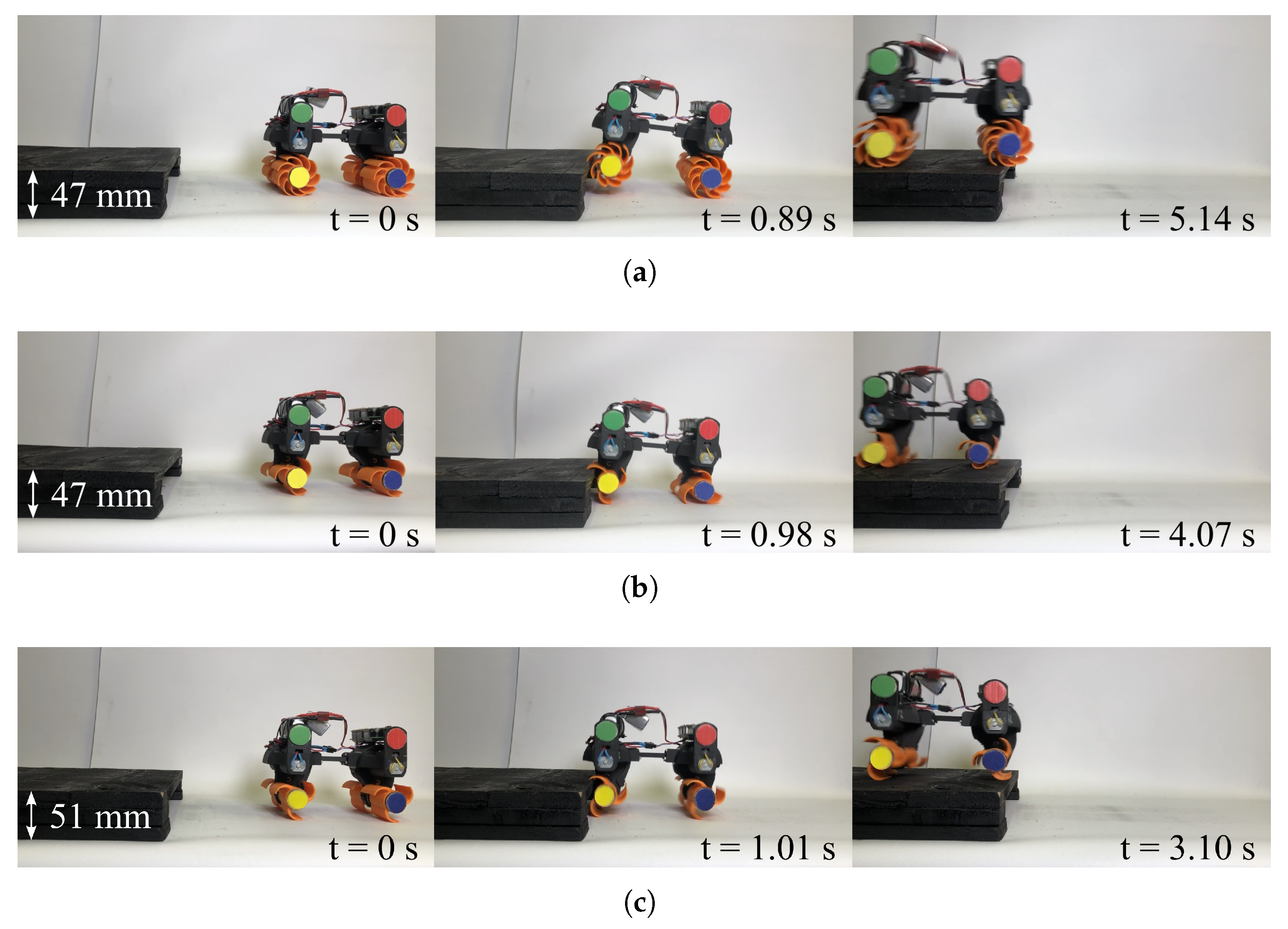
Figure 8.
Lateral tipping associated with instability caused by unsynchronized wheels: (a) 3-spoke wheel at a height of 1.7R (51 mm). (b) Tapered 3-spoke wheel at a height of 1.7R (51 mm).
Figure 8.
Lateral tipping associated with instability caused by unsynchronized wheels: (a) 3-spoke wheel at a height of 1.7R (51 mm). (b) Tapered 3-spoke wheel at a height of 1.7R (51 mm).
Figure 9.
Comparison of different configurations on tiled floor: (a–c) Show the frequency spectrum in the selected high-frequency range for each number of spokes fixed geometric profile, in both wheel rotation directions. (d–e) Show the frequency spectrum comparing the spoke wheel in the two rotation directions, as a function of the number of spokes and the spoke profile. (f-g) show the vertical acceleration and the frequency spectrum of the circular wheel and of the most significant cases.
Figure 10.
Comparison of different configurations on cobblestones: (a–c) Show the frequency spectrum in the selected high-frequency range for each number of spokes and fixed geometric profile, in both wheel rotation directions. (d–e) Show the frequency spectrum comparing the spoke wheel in the two rotation directions, as a function of the number of spokes and the spoke profile. (f-g) Show the vertical acceleration and the frequency spectrum of the circular wheel and of the most significant cases.
Table 1.
The different configurations of the wheel considered.
Table 2.
Successful trial time, mean time and standard deviation of the different wheel configurations (R = 30 mm).
Table 2.
Successful trial time, mean time and standard deviation of the different wheel configurations (R = 30 mm).
Disclaimer/Publisher’s Note: The statements, opinions and data contained in all publications are solely those of the individual author(s) and contributor(s) and not of MDPI and/or the editor(s). MDPI and/or the editor(s) disclaim responsibility for any injury to people or property resulting from any ideas, methods, instructions or products referred to in the content. |
© 2025 by the authors. Licensee MDPI, Basel, Switzerland. This article is an open access article distributed under the terms and conditions of the Creative Commons Attribution (CC BY) license (https://creativecommons.org/licenses/by/4.0/).
Copyright: This open access article is published under a Creative Commons CC BY 4.0 license, which permit the free download, distribution, and reuse, provided that the author and preprint are cited in any reuse.


