Submitted:
12 November 2025
Posted:
13 November 2025
You are already at the latest version
Abstract
One of the most important goals in developing centrifugal pumps for liquid hydrogen transport is to minimize the temperature rise of the working fluid caused by internal and external heat sources during operation. In this paper, as part of our evaluation of the internal insulation characteristics of a centrifugal pump for liquid hydrogen transport, we removed the external vacuum insulation layer and installed a Teflon insulation layer inside the pump. We investigated the heat transfer from the outside to the working fluid and the resulting temperature rise of the working fluid due to internal heat flux losses during the pumping process. The results show that, compared to a pump without a Teflon insulation layer, increasing the insulation layer thickness to 10 [mm] reduces external heat input from about 1,300 [W] to 300 [W]. Furthermore, the Teflon insulation layer reduces the heat generated by internal heat flow losses during pump operation from approximately 37 [W] to 11 [W].
Keywords:
liquid hydrogen
; centrifugal pump
; magnetic drive
; teflon insulation layer
; entropy production
; heat loss
1. Introduction
Hydrogen is considered a key energy source for the carbon-neutral era, as it emits zero greenhouse gases during combustion and has an energy density per unit mass three times that of gasoline. Therefore, technologies for storing and transporting hydrogen have emerged as key research topics [1,2,3]. The most efficient way to handle hydrogen is to convert room-temperature gaseous hydrogen into liquid form for storage and transportation. Liquid hydrogen at a cryogenic temperature of 20 [K] reduces its volume by about 800 times compared to gaseous hydrogen, allowing more hydrogen to be stored in the same space. It also allows for rapid transport of large quantities of hydrogen at once, eliminating the need for continuous compression, offering significant safety advantages. However, because liquid hydrogen can only exist at cryogenic temperatures, maintaining the extremely low temperatures during transport and storage is the biggest technological challenge [4,5].
Our research team has been conducting ongoing research related to the development of centrifugal pumps and valves for transporting liquid hydrogen. The most critical challenge in developing centrifugal pumps for transporting liquid hydrogen is minimizing heat transfer to the working fluid during operation. To achieve this, it is crucial to minimize internal heat generated due to flow loss of the working fluid during pump operation. To do this, we conducted research to optimize the design of the impeller and volute to minimize internal heat generation [6]. Furthermore, it is essential to minimize the heat transferred from the external environment to the liquid hydrogen, the working fluid, during operation. To this end, we adopted a magnetic drive centrifugal pump, which remotely drives the impeller instead of the impeller’s rotating shaft. This design prevents heat transfer from the motor shaft driving the impeller to the liquid hydrogen. Furthermore, all internal surfaces of the pump, including the impeller, which comes into direct contact with the liquid hydrogen, are insulated with Teflon, a cryogenic insulator.
In this paper, we applied a centrifugal pump with an impeller designed to minimize internal flow heat generation. To actively block external heat inflow, we lined all internal surfaces of the pump, including the impeller, with thick Teflon. Furthermore, we systematically analyzed the heat transfer phenomena occurring when pumping liquid hydrogen under these conditions using CHT analysis. Through this analysis, we aimed to determine the heat transfer-reducing effect of Teflon layer, an insulating material, in a centrifugal pump used for liquid hydrogen transport.
2. CFD Simulation Models and Boundary Conditions
Figure 1 shows the cross-section of the magnetic drive centrifugal pump employed in this study and the flow of the working fluid. As can be seen, the magnetic drive was used to fundamentally block the transfer of heat generated by the motor during operation to the cryogenic working fluid, liquid hydrogen. Furthermore, all surfaces in contact with the working fluid were lined with Teflon, a cryogenic insulator, to block heat transfer from the pump’s outer wall, which is exposed to the atmosphere, to the working fluid, liquid hydrogen.
Figure 2 illustrates the components of the centrifugal pump used in the CHT analysis. The upper part of the figure shows the main components of the pump, which transports liquid hydrogen. The lower part shows the drive section, which magnetically drives the impeller contained within the casing. In the CHT analysis, the motor body was treated as a single mass, and the temperature obtained through experiments during operation, 333.15 [K], was applied as the surface boundary condition for calculations.
Figure 3 shows the mesh used for the CHT analysis of these components. The final mesh configuration was determined through mesh independence analysis [ ]. The solid part, consisting of the 62 major components shown in Figure 2, was composed of approximately 68 million tetrahedral meshes, while the working fluid, liquid hydrogen, was composed of approximately 23 million tetrahedral and prismatic meshes. Considering the highly complex geometrical shapes of the components constituting the centrifugal pump, tetrahedral meshes were primarily used for mesh generation. In addition, five thin prism mesh layers were added to all channel walls to ensure that the Y+ value was less than 100 to sufficiently reflect the effects of the turbulence model of the working fluid during the analysis.
Table 1 shows the material properties and operating boundary conditions of the working fluid used in the CHT analysis. The CHT computational fluid analysis was performed using Ansys CFX, a specialized pump analysis software. The heat transfer properties of the solid components of the pump, not shown in Table 1, were determined using specific values provided by the material supplier. For the cryogenic insulator Teflon, a thermal conductivity of K=0.25 [W/m K] was used.
The CHT analysis is configured to perform an overall heat flow evaluation by simultaneously calculating the phenomenon of heat transfer to the liquefied hydrogen through the materials constituting the pump with a natural convection heat transfer rate determined by the value of h=15 [W/m^2] from the pump outer wall exposed to the ambient temperature condition of 20C during a series of flow analysis processes in which liquefied hydrogen at 1 bar and 20K enters the pump inlet through an impeller rotating at 3,450 rpm and exits the pump outlet at a flow rate of 0.118 kg/s. Finally, in order to confirm the heat blocking effect of the Teflon layer, which is an insulation material attached to block the heat entering the working fluid from the outside, a quantitative analysis of the heat blocking effect from the outside during operation was performed by changing the thickness of the insulation material. In addition, by utilizing the CHT analysis results, the heat generated by the internal flow loss of liquid hydrogen during pump operation and the heat entering the 20 [K] cryogenic liquid hydrogen through the pump body under the conditions of external ambient temperature (293.15 [K]) were separately analyzed.
3. Results and Discussions
Figure 4 shows a portion of the CHT analysis results. The figure shows the liquid hydrogen entering the pump inlet rotating through the complex flow path between the impeller and the magnetic drive and flowing out the outlet. Simultaneously, it shows the temperature distribution experienced by the liquid hydrogen and the pump body during operation, due to heat supplied from outside the pump and internal flow losses generated during the pumping process. The figure below shows heat transfer from the motor, which uses the experimentally measured temperature of 333.15 K as the surface boundary condition, to the impeller transporting the liquid hydrogen. Furthermore, this heat transfer is prevented from occurring through conduction within the pump due to the magnetic drive blocking the motor shaft.
Figure 5 shows the temperature distribution of the working fluid during operation, calculated by varying the thickness of the Teflon layer, the insulation defined in Figure 2. Comparing the figures, we can see that as the insulation thickness decreases, the overall temperature of the working fluid increases. In particular, a portion of the working fluid entering the pump inlet at 20 [K] passes through the narrow passage created between the magnetic drives, receiving heat from the pump wall and increasing its temperature.
Figure 6 shows the calculated changes in the average temperature at the pump outlet and the maximum temperature inside the pump when the insulation thickness was varied, as shown in Figure 5. The figure shows that as the insulation thickness increases, both the outlet temperature of the working fluid and the maximum temperature of the working fluid inside the pump decrease rapidly. This confirms that the insulation effectively blocks heat entering the working fluid from the outside during operation. However, not all sources of increased working fluid temperature during operation are external heat sources; internal flow losses during operation may also contribute.
Recent studies have used entropy production in the analysis of heat flow losses (which appear as temperature rise) occurring during the operation of fluid machinery [7,8,9]. According to references by Li and Herwig et al., the total entropy production rate (Spro) related to fluid machinery losses considering heat transfer is composed of a part due to flow and a part due to heat transfer, as shown in Eq. (1) [10,11,12,13]. The part due to flow is expressed as a part due to viscous dissipation (Spro,v̅) and a part due to turbulent dissipation (Spro,v′), as shown in Eqs. (2) and (3), respectively. And the part due to heat transfer is expressed as a part due to heat conduction due to the average temperature gradient (Spro,T̅) and a part due to heat conduction due to the fluctuating temperature gradient (Spro,T′), as shown in Eqs. (4) and (5). Equations (6) to (9) represent entropy production defined using the entropy production rate defined above. Each entropy production value is obtained by spatial integration of the entropy production rate generated by the working fluid during pump operation. The sum of these values is defined as the total entropy production value, which is expressed as the total heat flow loss occurring during pump operation, as in Equation (10).
Figure 7 shows the calculated entropy production rate (Spro,v′) changes due to the velocity fluctuation component of the working fluid when the insulation thickness is varied. As shown in the figure, Spro,v′ shows a nearly constant distribution regardless of the change in insulation thickness. As can be seen in the streamlines in Figure 4, Spro,v′ is distributed at a large value around the narrow balancing hole that extends from the back of the impeller to the front and the complexly structured pump inlet where turbulence is enhanced. From this, it can be seen that Spro,v′, which represents the loss due to the velocity fluctuation component among the losses due to the heat flow inside the pump during operation, has a constant value regardless of the insulation thickness.
Figure 8 shows the calculated entropy production rate (Spro,T′) changes due to the temperature fluctuation component of the working fluid when the insulation thickness was varied. The figure shows that Spro,T′ increases rapidly as the insulation thickness decreases. Unlike the entropy production rate (Spro,v′) due to the velocity fluctuation component shown in Figure 7, Spro,T′ occurs primarily around the pump inlet, where the external heat source rapidly mixes with the internal flow. Furthermore, when no insulation is applied, the entropy production rate due to the temperature fluctuation component is found to be high at the impeller outlet, in addition to around the pump inlet. This is believed to be due to the hot heat source from the motor entering the working fluid inside the pump along the wall, as shown in the lower figure of Figure 4. From these results, it can be seen that Spro,T′, which represent the loss due to temperature fluctuation among the losses due to heat flow inside the pump during operation, are closely related to the thickness of the insulation.
Figure 9 shows the results of calculating the entropy production values of the working fluid due to the average and fluctuating components of the temperature and the velocity within the pump according to changes in the insulation thickness using Equation (6)~(10). Looking at the graph plotted on a logarithmic scale, we can see that the heat flux loss due to the average temperature and velocity components of the working fluid during pump operation is negligible compared to the loss due to the fluctuating components. This is because the pump is a fluid machine that rotates at a high speed of 3450 rpm, so the flow is mainly dominated by turbulence. As shown in Figure 8 and Figure 9, the loss due to velocity fluctuations remains constant regardless of the insulation thickness, while the loss due to temperature fluctuations decreases rapidly with increasing insulation thickness. The total heat flow loss (PSpro), which is the sum of these values, shows a decreasing trend with increasing insulation thickness due to the loss due to temperature fluctuations. The total internal heat flow loss calculated using the target model pump under the operating conditions shown in Table 1 decreases from approximately 37 [W] when no insulation is used to about 11 [W] when lined with 10 [mm] of Teflon insulation.
Figure 10 shows the results of calculating the flow loss (PSpro) occurring inside the pump and heat transfer rate (Qwall) transmitted from the outside due to changes in insulation thickness. As shown in the figure, the heat conduction from the outside of the pump through the pump body to the working fluid inside the pump decreases rapidly as the thickness of the insulation increases. In addition, the heat flow loss of the internal working fluid also decreases rapidly as the thickness of the insulation increases. This is because, as explained in Figure 9, the heat entering from the outside decreases due to the increase in the thickness of the insulation, which reduces the temperature of the internal working fluid and thus the internal heat flow loss. Under the operating conditions shown in Table 1, the heat transferred from the outside to the internal working fluid calculated using the target model pump decreases from approximately 1300 [W] when no insulation was used to approximately 300 [W] when lined with 10 [mm] of Teflon as insulation. This confirms that approximately 97-98% of the total heat received by the working fluid (liquid hydrogen) during operation is from an external heat source. And when operated under the operating conditions given in Table 1 by these internal and external heat sources, the average outlet temperature of the model pump under study decreases from about 1.2 [K] when no insulation is used, as shown in Figure 6, to about 0.3 [K] when lined with 10 [mm] of Teflon as insulation.
4. Conclusions
One of the most important challenges in developing centrifugal pumps for liquid hydrogen transport is minimizing the temperature rise of the working fluid caused by internal and external heat sources during operation. This study was conducted to determine the effect of Teflon insulation installed inside the pump on the insulation of the working fluid during operation. To this end, the heat transfer phenomenon from an external heat source to the working fluid was evaluated when the external vacuum insulation layer was removed and only a Teflon insulation layer was installed inside the pump. Furthermore, the temperature rise of the working fluid due to internal heat flow losses during the internal pumping process was studied. The following conclusions were drawn from this research.
1. The magnetic drive system, which remotely drives the pump’s impeller, is effective in blocking external heat sources generated by the motor during pump operation from entering the working fluid inside the pump.
2. When the thickness of the insulation layer installed on the inner wall of the pump is increased from 0 to 10 [mm], the average temperature rise at the outlet of the liquid hydrogen, which is the working fluid at the outlet of the pump, is reduced from 1.2 [K] to 0.4 [K].
3. Among the losses due to heat flow inside a pump operating at a high speed of ,3450 [rpm], the heat loss due to the average components of velocity and temperature has a value that can be ignored when compared to the loss due to the fluctuating components.
4. Heat flow loss (PSpro,v′) due to velocity fluctuations remains constant regardless of insulation thickness, while heat flow loss (PSpro,T′) due to temperature fluctuations decrease rapidly with increasing insulation thickness. The sum of these values, the total heat flow loss (PSpro), tends to decrease with increasing insulation thickness due to losses due to temperature fluctuations.
5. During operation, the heat transferred from the outside of the pump to the internal working fluid is reduced from about 1300 [W] when no Teflon insulation is used to approximately 300 [W] when a 10 [mm] thickness Teflon insulation layer is used. Furthermore, it is shown that approximately 97 to 98% of the total heat received by the working fluid during operation from internal and external heat sources comes from external heat sources.
Author Contributions
Conceptualization, writing-original draft, investigation, data curation, writing-review and editing, methodology, resources, supervision, funding acquisition, project administration, J.E.Yun; formal analysis, software, validation, visualization, J.Y.Shin; formal analysis, C.Harsito; validation, resources, funding acquisition, project administration, W.S.Kim, H.S.Moon and S.S.Lee. All authors have read and agreed to the published version of the manuscript.
Funding
This work was supported by the Innovation System & Education(RISE) program through the Gangwon RISE Center, funded by the Ministry of Education(MOE) and the Gangwon State(G.S.), Republic of Korea.(2025-RISE-10-000)
Data Availability Statement
The original contributions presented in the study are included in the article, further inquiries can be directed to the corresponding author.
Acknowledgments
We would like to thank the staff at Fluonics Co., Ltd. for providing the magnetic drive pump experimental data that helped us complete this research paper.
Conflicts of Interest
The authors declare no conflicts of interest.
References
- Ishaq, H.; Dincer, I.; Crawford, C. A Review on Hydrogen Production and Utilization: Challenges and Opportunities. Int. J. Hydrogen Energy 2022, 47, 26238–26264. [CrossRef]
- Kapdan, I.K.; Kargi, F. Bio-Hydrogen Production from Waste Materials. Enzyme Microb. Technol. 2006, 38, 569–582. [CrossRef]
- Durbin, D.J.; Malardier-Jugroot, C. Review of Hydrogen Storage Techniques for on Board Vehicle Applications. Int. J. Hydrogen Energy 2013, 38, 14595–14617. [CrossRef]
- Staffell, I.; Scamman, D.; Velazquez Abad, A.; Balcombe, P.; Dodds, P.E.; Ekins, P.; Shah, N.; Ward, K.R. The Role of Hydrogen and Fuel Cells in the Global Energy System. Energy Environ. Sci. 2019, 12, 463–491. [CrossRef]
- Ma, Y.; Wang, X.R.; Li, T.; Zhang, J.; Gao, J.; Sun, Z.Y. Hydrogen and Ethanol: Production, Storage, and Transportation. Int. J. Hydrogen Energy 2021, 46, 27330–27348. [CrossRef]
- Harsito, C.; Yun, J. E.; Shin, J.Y.; Kim, J.M. Optimal Design of a Liquid Hydrogen Centrifugal Pump Impeller. Energies 2024,1-17. [CrossRef]
- Jia, X.; Zhang, X. Numerical Study on Local Entropy Production Mechanism of a Contra-Rotating Fan, Entropy 2023, 25(9), 1293. [CrossRef]
- Wang, Z.; Xie, B.; Xia, X.; Luo, L.; Yang, H.; Li, X. Entropy production analysis of a radial inflow turbine with variable inlet guide vane for ORC application, Energy 2023, 265(C), 1-15. [CrossRef]
- Zhou, L.; Hang, J.; Bai, L.; Krzemianowski, Z.; El-Emam, M. A.; Yasser, E.; Agarwal, R. Application of entropy production theory for energy losses and other investigation in pumps and turbines: A review. Applied Energy 2022, 318(C), 1-21. [CrossRef]
- Li, D.; Wang, H.; Qin, Y.; Han, L.; Wei, X.; Qin, D. Entropy production analysis of hysteresis characteristic of a pump-turbine model. Energy Conversion and Management 2017, 149, 175–191. [CrossRef]
- Herwig, H. The Role of Entropy Generation in Momentum and Heat Transfer. In Proceedings of the International Heat Transfer Conference IHTC14-23348, Washington, DC, USA, August 8-13, 2010. [CrossRef]
- Herwig, H.; Kock, F. Direct and Indirect Methods of Calculating Entropy Generation Rates in Turbulent Convective Heat Transfer Problems. Heat Mass Transfer 2007, 43(3), 207-215. [CrossRef]
- Kock, F.; Herwig, H. Entropy production calculation for turbulent shear flows and their implementation in CFD codes. International Journal of Heat and Fluid Flow 2005, 26(4), 672–680. [CrossRef]
- Yun, J. E., Shin, J.Y., Cartur, H., Kim, G. Y., and Kim, H. J., Kim, J.M. Turbine Performance of Variable Geometry Turbocharger Applied to Small Gasoline Engine Considering Heat Transfer Effect. Energies 2025, 1-17. [CrossRef]
Figure 1.
Cross-section of a magnetic drive centrifugal pump and the flow of working fluid inside the pump.
Figure 1.
Cross-section of a magnetic drive centrifugal pump and the flow of working fluid inside the pump.
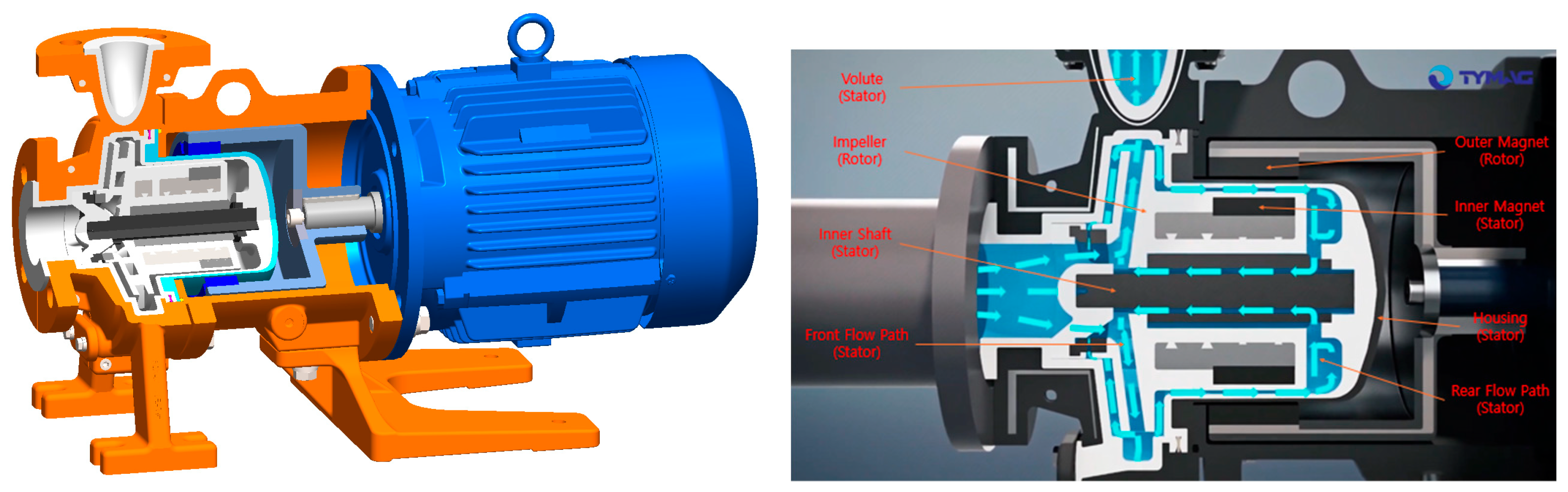
Figure 2.
Each component that makes up the magnetic drive pump: Definition of the thickness of the cryogenic insulation Teflon layer.
Figure 2.
Each component that makes up the magnetic drive pump: Definition of the thickness of the cryogenic insulation Teflon layer.
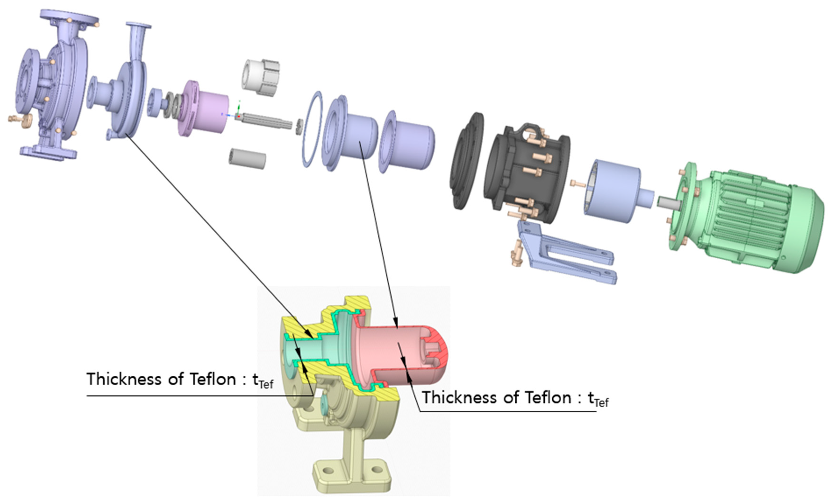
Figure 3.
Computational mesh for the analysis model of a magnetic drive centrifugal pump (solid part) and liquid hydrogen (fluid part) as the working fluid for CHT analysis.
Figure 3.
Computational mesh for the analysis model of a magnetic drive centrifugal pump (solid part) and liquid hydrogen (fluid part) as the working fluid for CHT analysis.
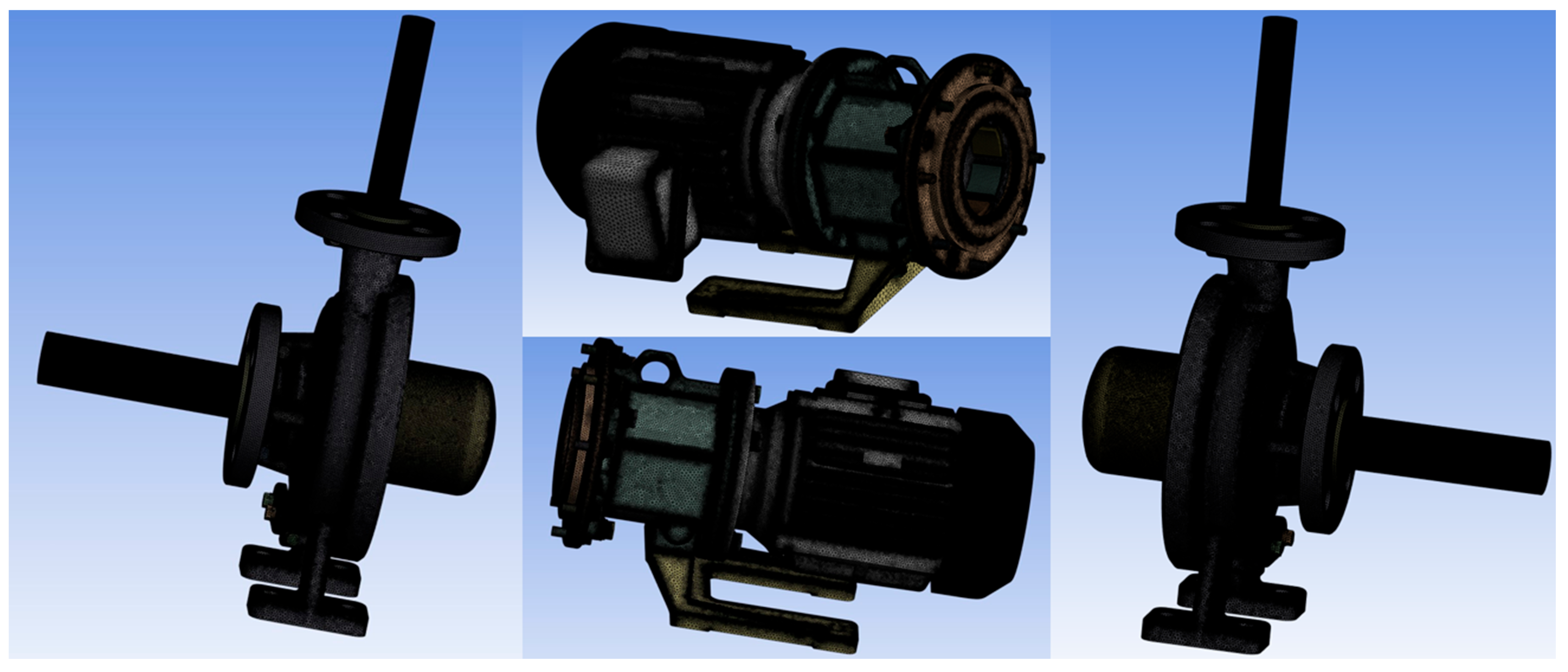
Figure 4.
CHT analysis results under the condition of insulation Teflon layer thickness tTef=4 [mm]: Temperature distribution of the pump and working fluid and streamline of the working fluid.
Figure 4.
CHT analysis results under the condition of insulation Teflon layer thickness tTef=4 [mm]: Temperature distribution of the pump and working fluid and streamline of the working fluid.
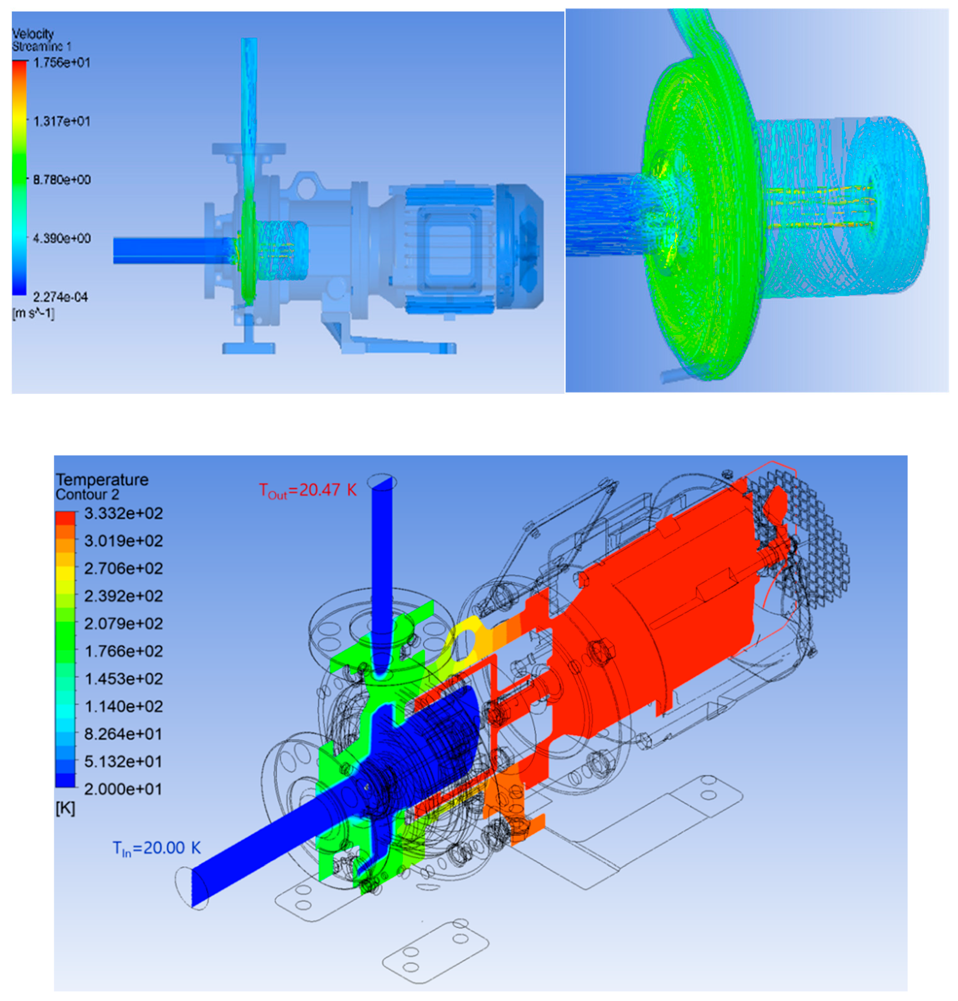
Figure 5.
Changes in temperature distribution of the working fluid inside the pump due to changes in insulation thickness (tTef).
Figure 5.
Changes in temperature distribution of the working fluid inside the pump due to changes in insulation thickness (tTef).
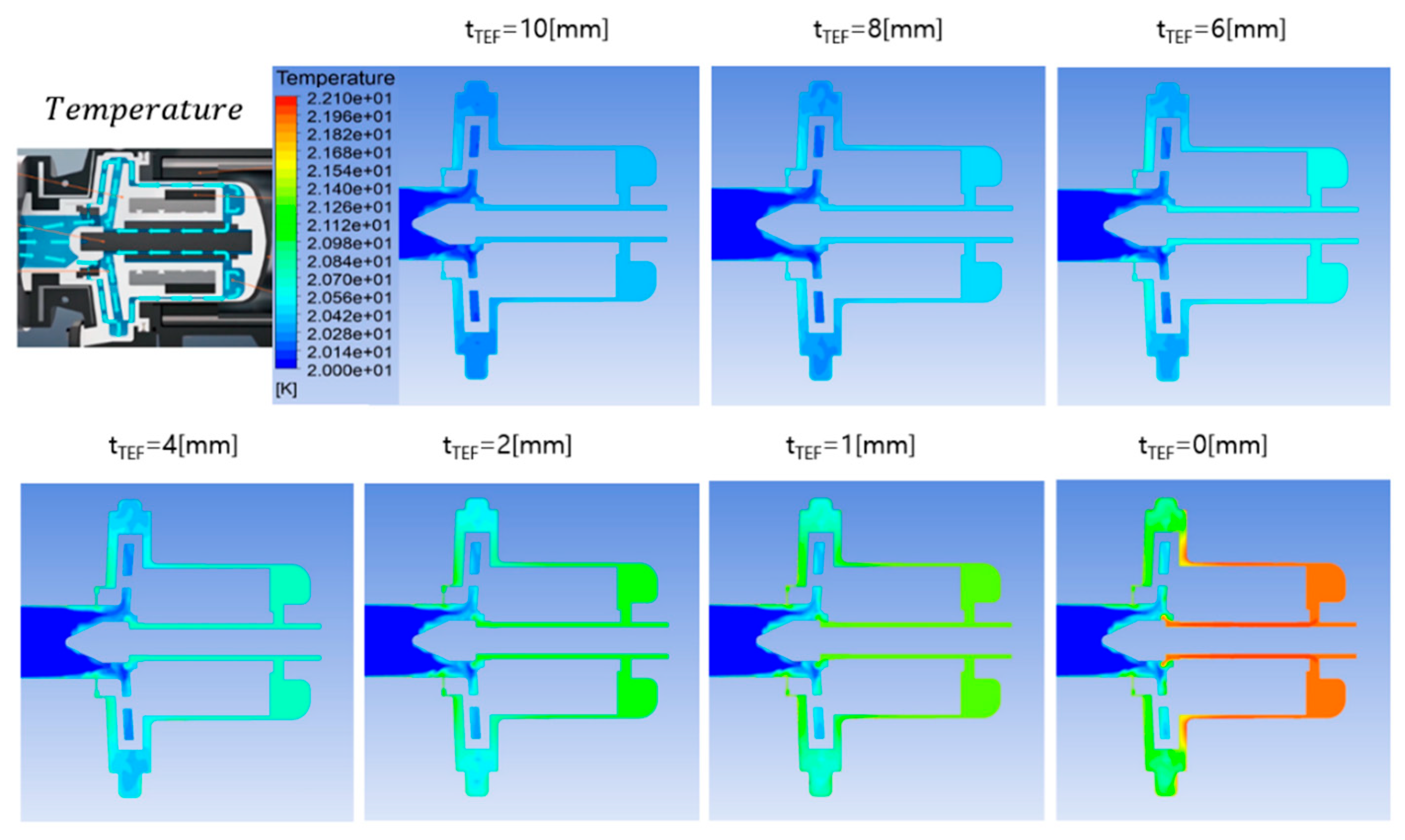
Figure 6.
Changes in the average temperature at the pump outlet of the working fluid and the maximum temperature inside the pump due to changes in insulation thickness (tTef).
Figure 6.
Changes in the average temperature at the pump outlet of the working fluid and the maximum temperature inside the pump due to changes in insulation thickness (tTef).
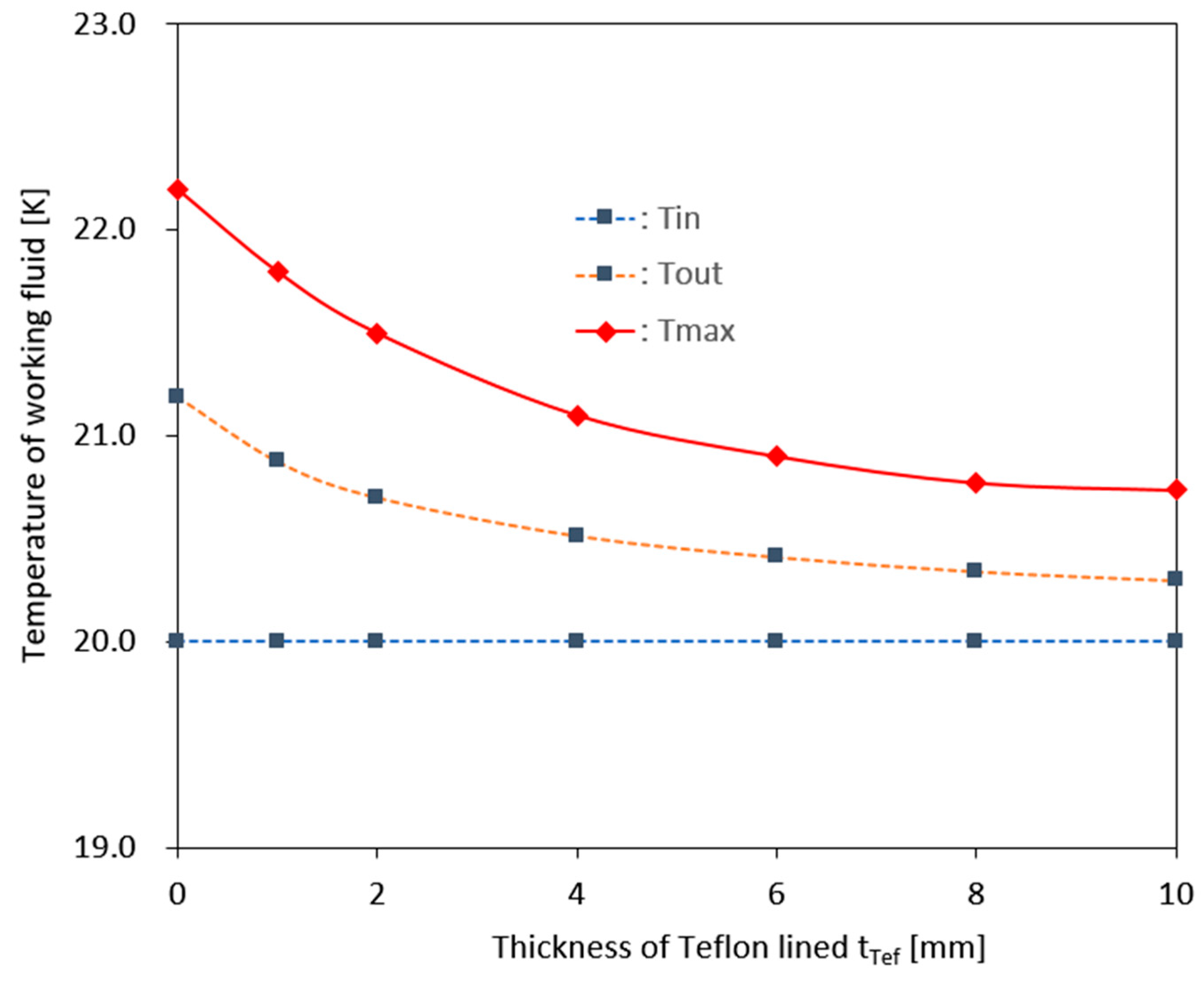
Figure 7.
Changes in the entropy production rate (Spro,v′) distribution due to the velocity fluctuation component of the working fluid in the pump according to changes in insulation thickness (tTef).
Figure 7.
Changes in the entropy production rate (Spro,v′) distribution due to the velocity fluctuation component of the working fluid in the pump according to changes in insulation thickness (tTef).
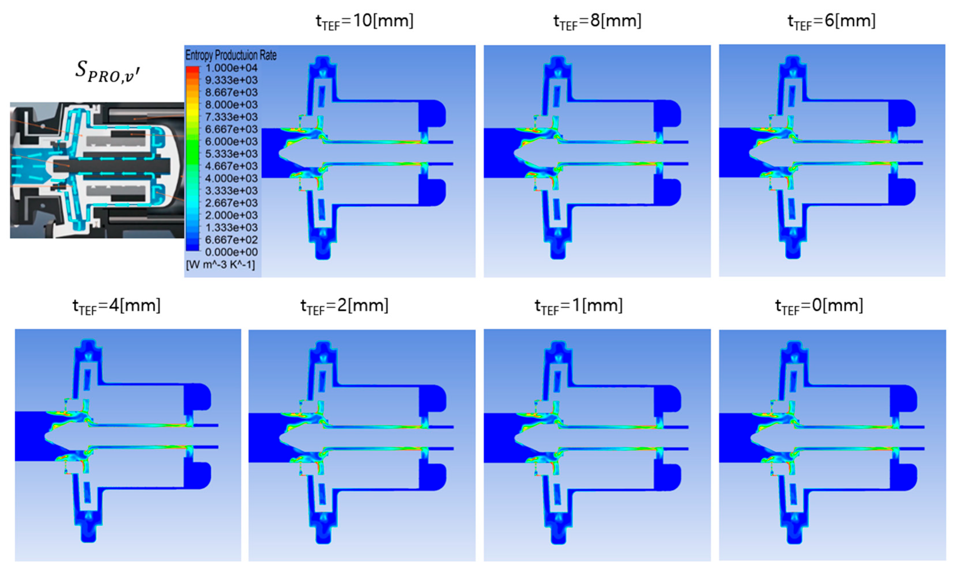
Figure 8.
Changes in the entropy production rate (Spro,T′) distribution due to the temperature fluctuation component of the working fluid in the pump according to changes in insulation thickness (tTef).
Figure 8.
Changes in the entropy production rate (Spro,T′) distribution due to the temperature fluctuation component of the working fluid in the pump according to changes in insulation thickness (tTef).
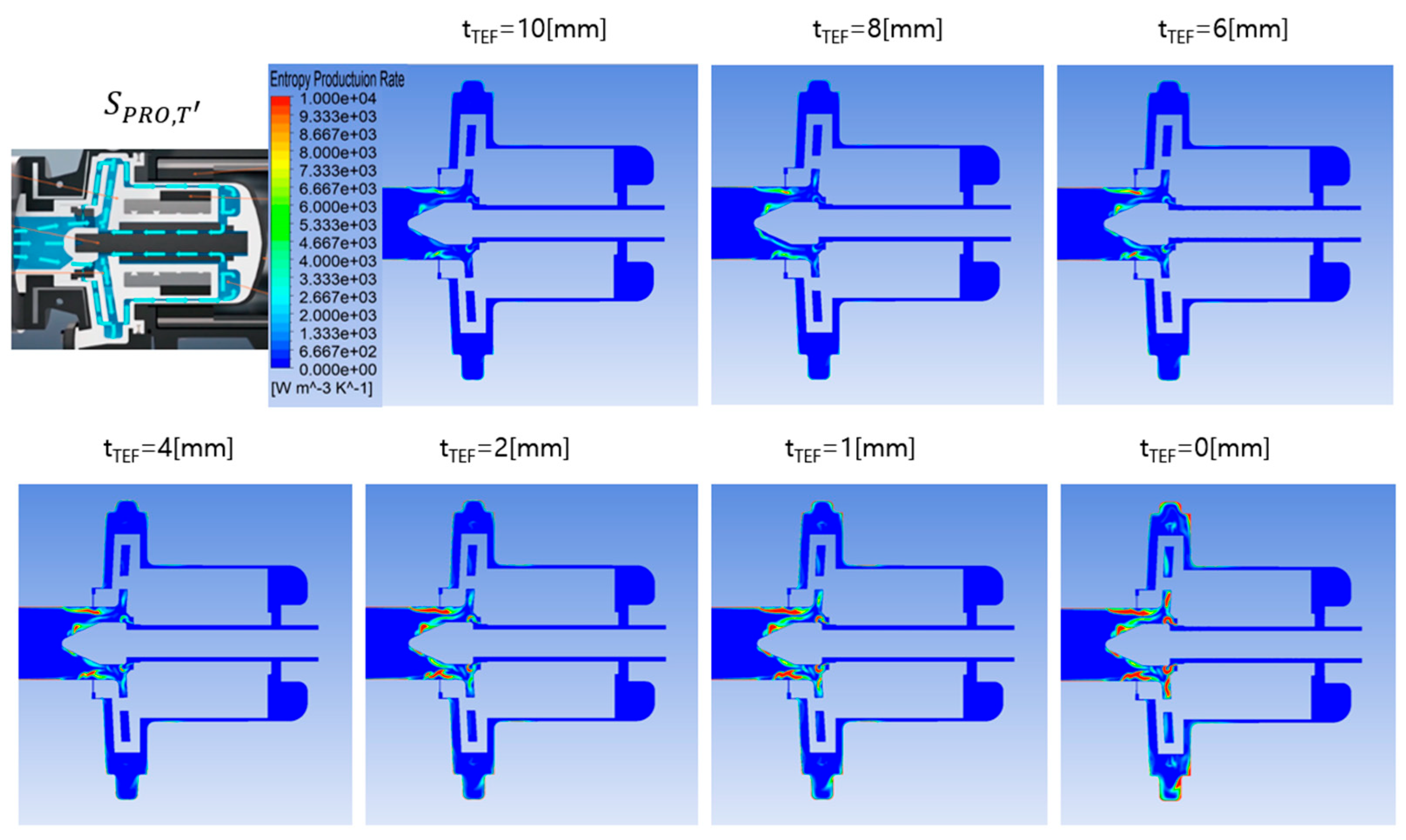
Figure 9.
Changes in the entropy production values of the working fluid due to the average and fluctuating components of the temperature and the velocity within the pump according to changes in the insulation thickness (tTef).
Figure 9.
Changes in the entropy production values of the working fluid due to the average and fluctuating components of the temperature and the velocity within the pump according to changes in the insulation thickness (tTef).
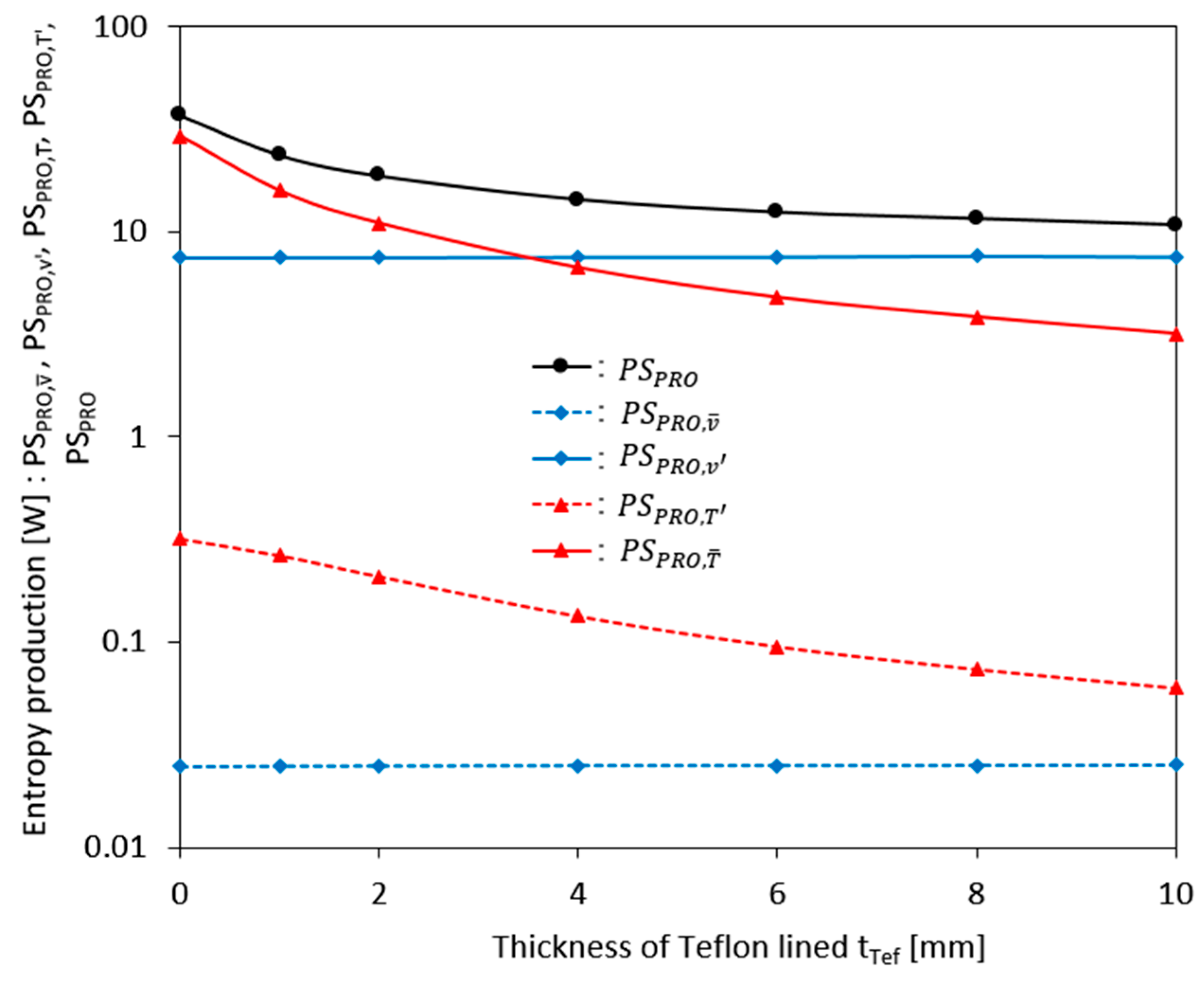
Figure 10.
Changes in flow loss occurring inside the pump and heat transfer rate transmitted from the outside due to changes in insulation thickness (tTef).
Figure 10.
Changes in flow loss occurring inside the pump and heat transfer rate transmitted from the outside due to changes in insulation thickness (tTef).
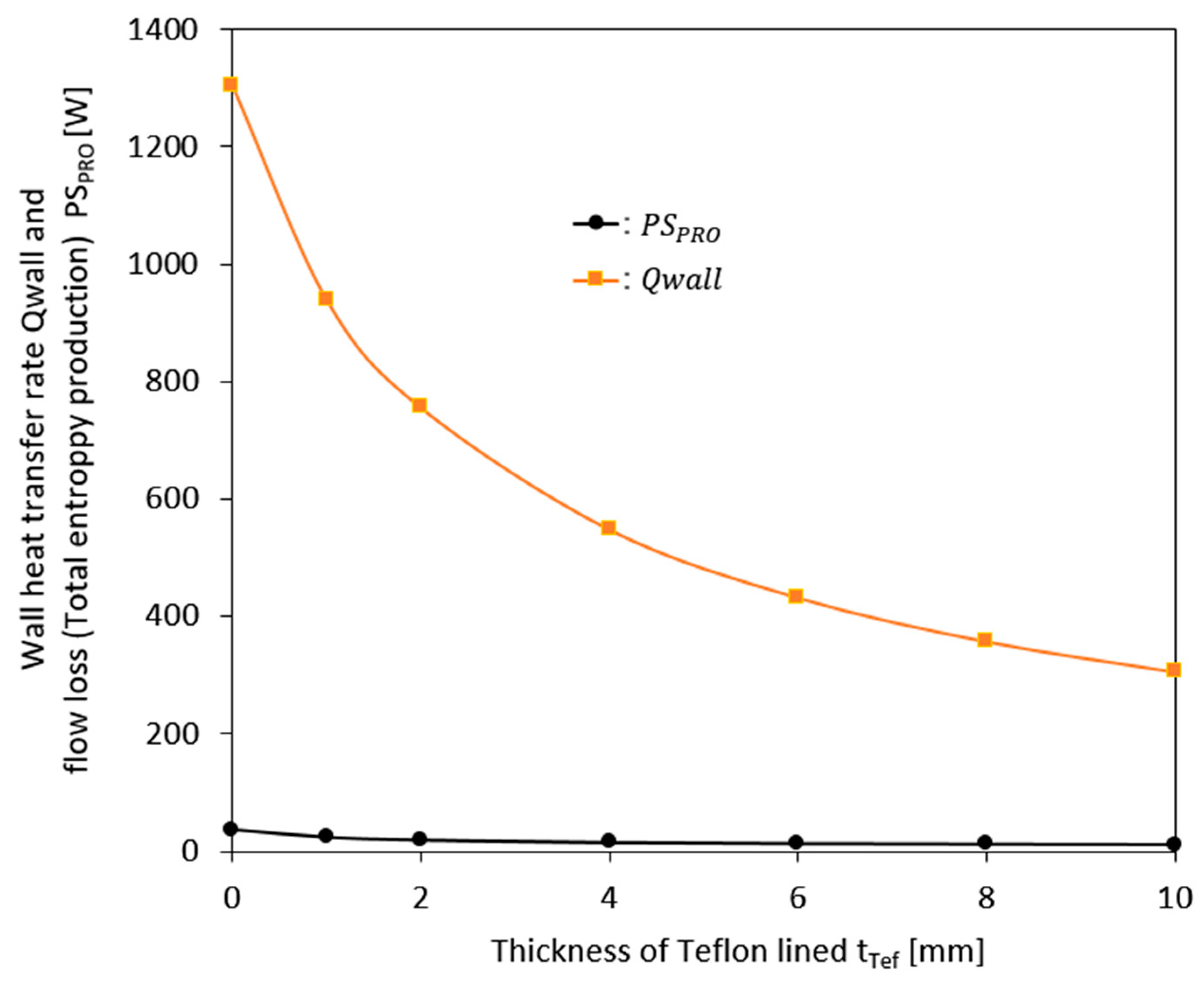

Table 1.
Physical properties of the working fluid, boundary conditions and mesh information.
| Grid information & Boundary conditions | ||
| Items | Conditions | |
| Fluid | Liquid Hydrogen | |
| Density [kg/m3] | 70.5 | |
| Specific heat capacity [J/kg K] | 9,580 | |
| Dynamic viscosity [kg/m s] | 1.3E-5 | |
| Thermal conductivity [W/m K] | 0.0984 | |
| Interface | Rotor-Stator | Stage |
| Other | General Contact | |
| Pump Inlet Boundary | Total Pressure=1[bar] | Temperature=20[K] |
| Pump Outlet Boundary | Flow Rate=0.118[kg/s] | |
| Turbulence Model | SST | |
| Heat Transfer Model | Thermal Energy | |
| Pump Head | 25[m] | |
| Pump Rotational Speed | 3,450[rpm] | |
| Heat Transfer Coefficient | h=15[W/m2] | |
| Air Temperature | Temperature=293.15[K] | |
| Number of Mesh | Fluid=23,214,142 | |
| Solid=68,025,440 | ||
Disclaimer/Publisher’s Note: The statements, opinions and data contained in all publications are solely those of the individual author(s) and contributor(s) and not of MDPI and/or the editor(s). MDPI and/or the editor(s) disclaim responsibility for any injury to people or property resulting from any ideas, methods, instructions or products referred to in the content. |
© 2025 by the authors. Licensee MDPI, Basel, Switzerland. This article is an open access article distributed under the terms and conditions of the Creative Commons Attribution (CC BY) license (http://creativecommons.org/licenses/by/4.0/).
Copyright: This open access article is published under a Creative Commons CC BY 4.0 license, which permit the free download, distribution, and reuse, provided that the author and preprint are cited in any reuse.


