Preprint
Article

This version is not peer-reviewed.

Biomechanical Comparative Evaluation of Atrophic Edentulous Maxilla Rehabilitation Using the All-on-6 Concept with Zygomatic Implant & Tilted Implant as Posterior Implant—Finite Element Analysis

A peer-reviewed article of this preprint also exists.

Submitted:

05 November 2025

Posted:

10 November 2025

You are already at the latest version

Abstract

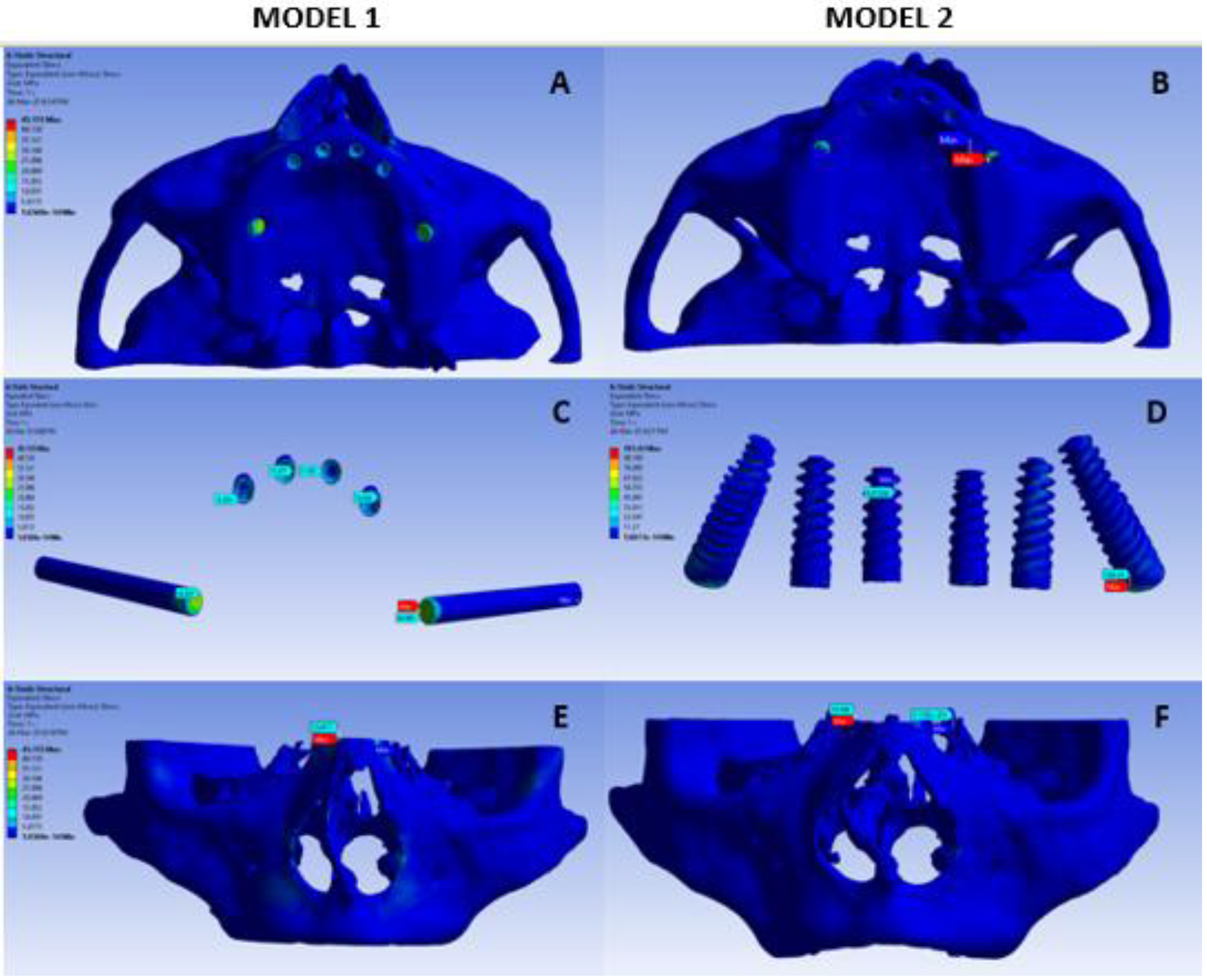
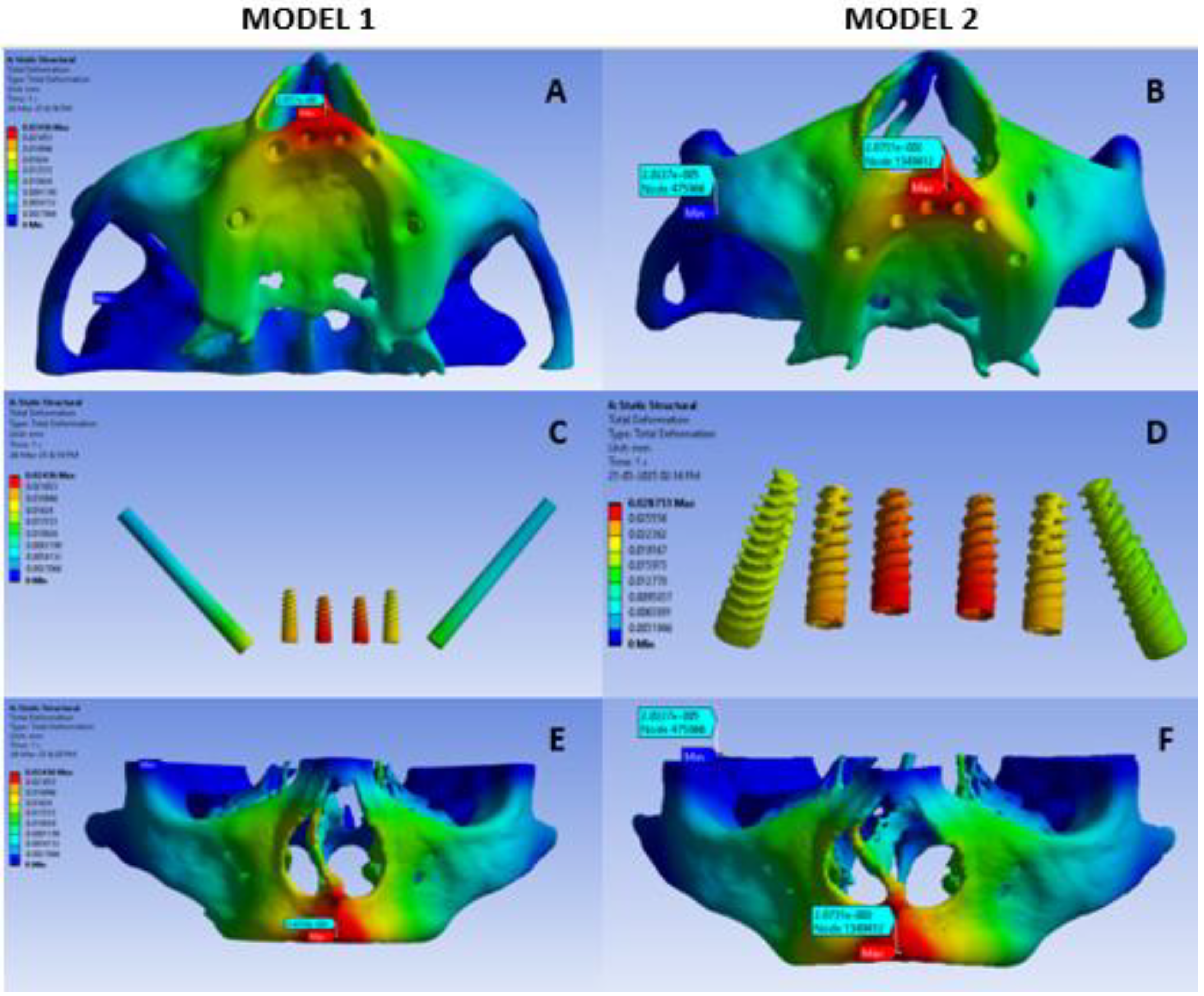
Background: All-on-6 implants are a reliable and efficient full-arch restoration option in patients with atrophic maxilla. Aim: The present study aimed to evaluate and compare the distribution of stress surrounding implants and adjacent osseous structures by utilizing all-on-six tilted and zygomatic methodologies in the maxillary region by using Finite element (FEA) analysis. Material and methods: Two finite element models were constructed with CT images of 50 years female. Model 1 was constructed with zygomatic implants, while model 2 was constructed with tilted implants.A vertical force of 150N on anterior component and 300N on posterior component were applied and maximum stress and deformation was assessed. Results: In the present study, the von Mises stress on the bone, implant and overall was higher in the tilted implant model than the zygomatic implant model. Conclusion: The findings of the present study suggests that zygomatic implants help distribute occlusal loads more favorably, especially under horizontal and combined loading conditions in all-on-six configuration.

Keywords: 
;  ;  ;  ;  ;  ;  ;  ;  

Introduction

Various methods of bone augmentation have been described for reconstructing the atrophic maxilla. Among them are autogenous block bone grafting; onlay and interpositional bone grafts (smile osteotomy); guided bone regeneration (GBR) with a particular graft; ridge splitting or expansion technique; osteotomies of the ridge or the jaws; distraction osteogenesis; microvascular free flaps; and Le Forte 1 osteotomies combined with bone grafting. Each of these methods has its advantages and disadvantages [1].
Rehabilitation of the atrophic maxilla, particularly in Bedrossian Classification Zone 1 [2], presents a significant clinical challenge for implant-supported prostheses. Traditionally, the All-on-4 concept [3] has been widely used to manage such cases. However, approaches suggest the use of an All-on-6 concept, involving either four axial and two tilted implants, or a configuration consisting of four axial implants and two zygomatic implants [4,5].
In prosthetic rehabilitation of completely edentulous patients, “All-on-six” implant technique is a viable option providing functional and aesthetic rehabilitation with fewer implants. The strategic placement of six implants often eliminates the need for bone grafting, making it suitable for patients with moderate bone loss who might not qualify for traditional implants.[6,7]
However, in “All-on-six” technique, implants are intentionally angled primarily to obtain anchorage from denser cortical bone areas, increasing primary stability and avoiding critical areas like the maxillary sinus or inferior alveolar nerve [8]. Additionally, tilted implants allow a wider anterior-posterior spread of the implant support, leading to better biomechanical load distribution and reduced stress on the bone and prosthesis [9]. On the other hand, Zygomatic implants are especially suitable in severely atrophic maxillae, where bone volume is insufficient for conventional implants. They obtain anchors from the dense zygomatic bone, bypassing the need for sinus augmentation or bone grafting, thus reducing surgical morbidity and treatment time [8,9].
Literature reveals that angulation of the implant, loading direction, different internal connections, and type of bone influences the von Mises stress in the respective peri implant area [10,11]. Higher stress around tilted implants may increase risk of bone resorption [12].
Considering the high utilization of the all-on-six implants in prosthetic rehabilitation of completely edentulous patients, it is necessary to evaluate the biomechanical response of zygomatic and tilted implants under masticatory loads to anticipate the outcomes and changes in the maxillofacial complex caused by the implants and masticatory forces. Understanding the stress distribution and displacement patterns of the all-on-six implants and maxillofacial complex under masticatory loads, can aid in improved selection, planning with respect to implant material, length, diameter, angulation, and other factors.
The present study aimed to evaluate biomechanically the distribution of stress surrounding implants and adjacent osseous structures by utilizing all-on-six concept with zygomatic and tilted implants as posterior implants in rehabilitation of atrophic edentulous maxilla

Materials and Methods

Study design: Finite Element Analysis
Study Setup: Conducted in the Department Of Oral And Maxillofacial Surgery of our institution.
Ethical standards:Informed consent was obtained prior to the start of the study.
Study Model
A. 
Model 1: Zygomatic Implants as Posterior Implants and Four Axial Implants in Anterior Maxilla
B. 
Model 2: Tilted Implants as Posterior Implants and Four Axial Implant In Anterior Maxilla

Steps of Method

1. 
Case Selection
A three-dimentional finite element model of the maxilla was developed using CT scan of a 50 year old female patient. High-resolution multi-slice CT scan was performed on the head and neck region by CT scanner. The voxel size was non-isotropic, with a slice thickness of 1 mm.
2. 
DICOM and STL Files conversion
A CT DICOM file was sent to the Biomechanical engineer. All data in Digital Imaging and Communications in Medicine(DICOM) format were imported. The CT image was converted into STL file format using BlueSky Bio Software. A 3-dimentional reconstruction of images was produced with a surface triangulation technique. For this purpose, a redefinition of edges and surfaces from scanned images was conducted in order to build a simplified model covering most of the volume of original geometry .
Throughout the process special care was taken to keep the surfaces of the implant in contact with the bone as faithful as possible to the original. Designing of the implant done by a design tool present in the Geometric free form 3-D software.
3. 
Construction Of The Basic Finite Element Model Of Maxilla
After constructing the 3D model, it was converted to a Finite Element Model (FEM) using “Free Form’’ Software. Then the Maxilla model is imported in “BlueSky Bio” Software.
In BlueSky Bio, maxilla model analysed and checked. The geometry data were imported into a generally accepted, and already commercially available, fem program, ANSYS WORKBENCH 2022R1.
The properties of the bone were assumed to be isotropic, homogenous and linearly elastic. The behaviour of the bone was characterized by two constants (Young modulus and Poisson ratio)(Table 1).
4. 
Construction Of Maxillary Model With Implants
The dimensions and specifications of the different implants were entered into the software and three-dimensional models of the implants along with maxilla were created with exact geometry. zygomatic and conventional implants were inserted into the craniofacial model.
FEA models of zygomatic and conventional tilted implants were constructed 3-dimensionally based on the dimensions from the manufacturer’s catalog.
The length of the implants were selected according to anatomical contours :
Zygomatic implant : 4.2×45 mm
Tilted posterior implants = 4.2×16 mm
In both models, the dimension of the Anterior implant was 3.5×10mm in the central incisor region and 3.75×11.5mm in the canine region. These dimensions were chosen because of the reduced alveolar bone width in the anterior region.
The implants were placed in the skull model, resulting in maximum contact with the bone. The apices of the posterior zygomatic implants were placed as close to the external surface of the zygomatic bone as possible or just extruding through the surface.
All models were imported as different files and 2 model groups were created as model 1 (Zygomatic Implants as Posterior Implants & Four Axial Implant In Anterior Maxilla) and model 2 (Tilted Implants as Posterior Implants and Four Axial Implant In Anterior Maxilla).
5. 
Occlusal Loading
With an adequate and simplified geometric finite element model and the appropriate material properties, along with the occlusal loading and support conditions, the finite element solver module of the ANSYS software carried out the mathematical procedure, and displacement and stress values for each node as well as element were obtained.
A vertical force of 150N on anterior component and 300N on posterior component were applied simulating load transfer from the prosthesis. It was considered that the force was uniformly distributed through the connector to the component of implants. The response was recorded as per the software settings for the maximum stress on the underlying remaining bone and on respective implants along with displacement and deformation.
6. 
Finite Element Analysis
On application of the occlusal forces, the total structural deformation of the implants, along with the bone and Von Mises Stresses generated, were obtained and recorded for each configuration of implants using the computerized software. By analysing the VM stresses predicted by the model for each configuration, and total structural deformation of the implant in each configuration, we could analyze which implant configuration provides the greatest stability.
VM stress is a value used to determine whether a given material will yield or fracture under a given load. If the VM stress is greater, the material is expected to yield or fracture. Hence, configuration with the lowest relative VM stress and the least structural deformation were likely to be the most stable.

Results

The stress and deformation in both the models is summarised in Table 2. The overall stress in model 1 ranges from 1.65 e-14 MPa to 45.155 MPa as represented by the blue colour coded image (Figure 1A) In model 1- stress on the implant ranged from 8.02 e-02 MPa to 44.869 MPa and high stress was noted in the neck of the screw. Among the six screws highest stress was observed in the zygomatic implants followed by the anterior implant. (Figure 1C) The stress on Bone in model 1 ranges from 1.65 e-14 MPa and 18.418 MPa and is represented in Figure 1E.
The overall deformation in model 1 ranges from 0-0.024 mm as represented by the colour coded image (Figure 2A). The highest deformation in model 1 was noted as a red colour region in the anterior maxilla. The deformation reduces gradually posteriorly and is represented as red to yellow rather than to green colour. (Figure 2C) In model 1- deformation on the implant ranged from 0.0036 mm and 0.023 mm and high deformation was noted in the anterior Implant in incisor region followed by the anterior implant in the Canine region and least was noted in Zygomatic implants. (Figure 2E) The deformation on Bone in model 1 ranges from 0-0.024 mm and is represented in Figure 2E. Highest deformation occurred in the premaxillary region.
The overall stress in model 2 ranges from 1.6077e-014 MPa to 101.43 MPa as represented by the blue colour coded image (Figure 1B) In model 2- stress on the implant ranged from 0.97 MPa to 100.29 MPa and was coded blue. All the six screws showed minimal stress in the tilted implants model. (Figure 1D) The stress on Bone in model 2 ranges from 1.6077e-013 MPa and 19.54 MPa and is represented in Figure 1F.
The overall deformation in model 2 ranges from 0-0.024 mm as represented by the colour coded image (Figure 2B). The highest deformation was noted as a red colour region in the anterior maxilla. The deformation reduces gradually posteriorly and is represented as red to yellow rather than to green colour. Deformation is also noted in the zygomatic bone, maxilla and nasal spine.(Figure 2D) In model 2- deformation on the implant ranged from 0.016 mm and 0.027 mm and high deformation was noted in the anterior Implant in incisor region followed by the anterior implant in the Canine region and least was noted in tilted implants. (Figure 2D) The deformation on Bone ranges in model 2 from 0-0.028 mm and is represented in Figure 2F. Highest deformation occurred in the premaxillary region. Von Misses Stress on both the models is comparable. Also the total deformation and bone deformation of both the models is comparable too.

Discussion

Finite element analysis (FEA) is a computational technique widely used to evaluate stress distribution patterns. FEA is a numerical simulation technique used to predict how objects or structures behave under various physical conditions such as forces, heat, pressure, or vibration [13,14]. In the present study FEA analysis was used to assess and compare the stress and deformation pattern in all-on-6 dental implant systems with zygomatic and tilted Implants under masticatory forces.
In the present study, the von Mises stress on the bone, implant and overall was higher in the tilted implant model than the zygomatic implant model. These findings were in accordance with study by Tezerişener et al [15] who observed that higher stress values were observed in both cortical and trabecular bone around the 45°-tilted posterior implants while the lowest stress was determined in the model including anterior dental implant combined with zygomatic implants. However, Tezerişener et al had investigated the all-on- four concept which is in contrast to the present study.
In the current study, the highest maximum principal stress in cortical bone was observed in model 2 suggesting that tilting the posterior implant by 45° caused an increase in tensile stress around this implant compared to the first model. Similar findings were observed by Pellizzer et al [16]. They reported an increase in stress accumulation as the angle of implant increased.
In the present study, in the model 1, high stress was noted in the neck of the screw. This was in accordance with studies by Silva et al [17] and Tezerişener et al [15]. Zygomatic implants combined with 2 to 4 conventional implants has been considered to be the ideal treatment option if the bone volume in anterior maxilla is sufficient. [18,19] Another study revealed an implant system incorporating one zygomatic implant with multiple standard implants showed lower maximum principal stress values in maxilla rather than with two zygomatic implants or only tilted implants [20].
In the present study, the total deformation values ranged from 0 to 0.024 mm in Model 1 and up to 0.028 mm in Model 2; implant deformation was up to 0.023 mm in Model 1 and 0.027 mm in Model 2. Similarly, in Saber et al study [21], a low deformation magnitudes. Additionally their study also revealed that increasing the inclination in posterior implants resulted in reduction of cantilever length and maximum stress decline in both cancellous and cortical bone. These findings indicate that both implant designs maintain structural integrity under physiological masticatory loads without excessive displacement detrimental to osseointegration [21].
The findings of the present study suggests that zygomatic implants help distribute occlusal loads more favorably, especially under horizontal and combined loading conditions. These findings were in accordance with study by Jaiswal et al [22] who revealed that the all-on-6 treatment concept showed the most favorable biomechanical behavior with consistently better stress measurements on the cortical bone and implants than that obtained from all-on-4 configuration.
In reviewing the literature, no data was found that compared the biomechanical behaviour of zygomatic implants and the tilted implant in All-on-six system in prosthetic rehabilitation of atrophic maxilla. The results of the present study indicates that the zygomatic implant reduces biomechanical stress on maxillary bone compared to tilted implants and thereby eliminating the unnecessary bone resorption due to excess stress distribution.The increase in anteroposterior span of prosthesis will give a better masticatory force distribution and overall satisfaction to patients.

Limitations

The present study has few limitations. Firstly, the FEA models are simplifications of complex biological systems and rely on assumptions such as isotropic, homogeneous, and linearly elastic material properties for bone and implant components, which do not fully replicate the anisotropic and heterogeneous nature of human bone. Secondly, the models typically consider ideal osseointegration with 100% implant-bone contact, which may not correspond to clinical reality where variations in bone quality, healing, and implant stability exist. Thirdly, the loading conditions in FEA are usually static and simplified (axial or oblique forces) and may not reflect the multidirectional and dynamic masticatory forces encountered in vivo. Lastly, software limitations and mesh quality may introduce computational errors affecting result reliability.

Future Perspective

In future, development of dynamic loading conditions mimicking actual mastication cycles and parafunctional habits need to be integrated into simulations for more comprehensive biomechanical evaluation. Additionally, FEA Models constructed with various degrees of tilt, different implant length and diameter should be investigated to draw a conclusion.

Conclusion

All-on-6 full-arch maxillary rehabilitation as a biomechanically favorable and minimally invasive approach for completely edentulous patients with compromised bone anatomy. The present finite element analysis demonstrates that zygomatic implants, when combined with standard dental implants All-on-six system can effectively reduce stress concentrations in the atrophic maxillary bone compared to configurations on tilted implants offering superior load distribution in full-arch rehabilitations.
Funding Source: This research did not receive any specific grant from funding agencies in the public, commercial, or not-for-profit sectors.

Conflicts of Interest

The authors have no conflict of interest to declare.

References

  1. Blanc O, Shilo D, Weitman E, Capucha T, Rachmiel A. Extramaxillary Zygomatic Implants: An Alternative Approach for the Reconstruction of the Atrophic Maxilla. Ann Maxillofac Surg. 2020 Jan-Jun;10(1):127-132. [Medline: 32855928]. [CrossRef]
  2. Aalam AA, Krivitsky-Aalam A, Kurtzman GM, Mahesh L. The severely atrophic maxilla: Decision making with zygomatic and pterygoid dental implants. J Oral Biol Craniofac Res. 2023 Mar-Apr;13(2):202-206. [Medline: 37065973]. [CrossRef]
  3. Taruna M, Chittaranjan B, Sudheer N, Tella S, Abusaad M. Prosthodontic perspective to all-on-4® concept for dental implants. J Clin Diagn Res. 2014 Oct;8(10):ZE16-9. [Medline: 25478475]. [CrossRef]
  4. Gaviria L, Salcido JP, Guda T, Ong JL. Current trends in dental implants. J Korean Assoc Oral Maxillofac Surg. 2014 Apr;40(2):50-60.
  5. Arora A, Upadhyaya V, Parashar KR, Malik D. Evaluation of the effect of implant angulations and impression techniques on implant cast accuracy - An in vitro study. J Indian Prosthodont Soc. 2019 Apr-Jun;19(2):149-158.
  6. Solomon O, Chetrus V, Zaharescu A, Leata R, Ilie M, Covaci AM, Earar K. “ ALL-ON-6”, Advantages and disadvantages of this modern dental restoration solution. Romanian Journal of Oral Rehabilitation. 2024 Oct 1;16(4).
  7. Forna DA, Constantin BC, Mihali M, Tiutiucă C, Earar K. Complex maxillary and mandibular oral rehabilitation using the all-on-6 concept, case report. Romanian Journal of Oral Rehabilitation. 2023 Apr;15(2):204-12.
  8. Moraru MC, Buzduga CM, Gurzu IL, Mereuta VD, Ciurcanu OE, Balan M, Al Hage E. the advantage of the all-on-six and all-on-eight technique compared to the all-on-four technique. Romanian Journal of Oral Rehabilitation. 2024 Jan;16(1).
  9. Gümrükçü Z, Korkmaz YT. Influence of implant number, length, and tilting degree on stress distribution in atrophic maxilla: a finite element study. Medical & biological engineering & computing. 2018 Jun;56:979-89.
  10. Khatib I, Joshi NV, Rao P, Joshi M, Shetty A, Thorat V, Talreja P. Effect of Implant-Abutment Connection and Abutment Angulations on Peri-implant Stress Levels: A Finite Element Analysis Study. Compendium of continuing education in dentistry (Jamesburg, NJ: 1995). 2024;45(7):e5-9.
  11. de Souza Rendohl E, Brandt WC. Stress distribution with extra-short implants in an angled frictional system: A finite element analysis study. The Journal of Prosthetic Dentistry. 2020 Dec 1;124(6):728-e1.
  12. Venkat Ratna Nag P, Sarika P, Bhagwatkar T, Dhara V. Angulated implant a novel concept for rehabilitation of severe atrophic maxilla with 3 years follow up supported by Finite Element Analysis. J Osseointegr 2020;13(1):39-44.
  13. Shivakumar S, Kudagi VS, Talwade P. Applications of finite element analysis in dentistry: A review. Journal of International Oral Health. 2021 Sep 1;13(5):415-22.
  14. Piccioni MA, Campos EA, Saad JR, de Andrade MF, Galvão MR, Abi Rached A. Application of the finite element method in dentistry. Revista Sul-Brasileira de Odontologia. 2013;10(4):369-77.
  15. Tezerişener HA, Özalp Ö, Altay MA, Sindel A. Comparison of stress distribution around all-on-four implants of different angulations and zygoma implants: a 7-model finite element analysis. BMC oral health. 2024 Feb 3;24(1):176.
  16. Pellizzer EP, Falcón-Antenucci RM, de Carvalho PSP, Sánchez DMIK, Rinaldi GAT, de Aguirre CC, et al. Influence of implant angulation with different crowns on stress distribution. J Craniofac Surg. 2011;22(2):434–7.
  17. Silva GC, Mendonca JA, Lopes LR, Landre Jr J. Stress patterns on implants in prostheses supported by four or six implants: a three-dimensional finite element analysis. International Journal of Oral & Maxillofacial Implants. 2010 Apr 1;25(2).
  18. Bedrossian, E. Rehabilitation of the edentulous maxilla with the zygoma concept: a 7-year prospective study. Int J Oral Maxillofac Implants. 2010;25(6):1213–21.
  19. Abouelhuda AM, Ibrahim AM, Elkenawy MH, Hegazy SA. Maxillary All-on-6 Treatment Using Zygomatic Implants. Bone Loss Evaluation by CBCT: 3-Year Follow-up. International Journal of Prosthodontics. 2025 Jan 1;38(1).
  20. Yemenoglu H, Beder M, Yaylacı M, Dizdar A, Alkurt M, Naralan ME, Yaylacı EU, Özdemir ME, Öztürk Ş, Yeşil Z. Evaluation of prostheses retained zygomatic and dental implants in large defects in the maxilla due to tumors or major trauma by biomechanical 3- dimensional finite element analysis. BMC Oral Health. 2025 Jan 19;25(1):99. [CrossRef] [PubMed] [PubMed Central]
  21. Saleh Saber F, Ghasemi S, Koodaryan R, Babaloo A, Abolfazli N. The Comparison of Stress Distribution with Different Implant Numbers and Inclination Angles In All-on-four and Conventional Methods in Maxilla: A Finite Element Analysis. J Dent Res Dent Clin Dent Prospects. 2015 Fall;9(4):246-53. [CrossRef]
  22. Jaiswal SB, Jain S, Jain V, Grover RK, Kale AA, Talreja L. Evaluation and Comparison of Stresses Between All-on-4 and All-on-6 Treatment Concepts With Three Different Prosthetic Materials in the Maxilla: A Finite Element Analysis Study. Cureus. 2024 Oct 13;16(10).
Figure 1. A] Overall Stress in Model 1; B] Overall Stress in Model 2; C] Stress on the Implant of Model 1; D] Stress on the Implant of Model 2; E] Stress on the Bone of Model 1; F] Stress on the Bone of Model 2.
Preprints 183795 g001
Figure 2. A]Overall Deformation in Model 1; B] Overall Deformation in Model 2; C] Deformation of the Implants in Model 1; D] Deformation of the Implants in Model 2; E]Deformation of the Bone in Model 1; F]Deformation of the Bone in Model 2.
Preprints 183795 g002
Table 1. Young’s Modulus and Poisson Ratio.
Material Young’s Modulus(MPa) Poisson’s Ratio Tensile Yield Strength(MPa)
Titanium 110000 0.35 834
Cortical bone 13700 0.3 114
Cancellous bone 1370 0.3 52
Table 2. Stress & Deformation in the Model 1 & Model 2.
MODEL 1 MODEL 2
Sr. No. Sensor Name Minimum Maximum Minimum Maximum
1 Von Mises Stress Overall(MPa) 1.65 e 14 MPa 45.155 MPa 1.6077 e 014 MPa 101.43 MPa
2 Von Mises Stress Implant(MPa) 9.02 e 02 MPa 44.869 MPa 0.97MPa 100.29 MPa
3 Von Mises Stress Bone(MPa) 1.65 e 14 MPa5 18.418 MPa 1.6077 e 013 MPa 19.54 MPa
4 Total Deformation(mm) 0 mm 0.024 mm 0 mm 0.028 mm
5 Implant Deformation(mm) 0.0036 mm 0.023 mm 0.016 mm 0.027 mm
6 Bone Deformation(mm) 0 mm 0.024 mm 0 mm 0.028 mm
Disclaimer/Publisher’s Note: The statements, opinions and data contained in all publications are solely those of the individual author(s) and contributor(s) and not of MDPI and/or the editor(s). MDPI and/or the editor(s) disclaim responsibility for any injury to people or property resulting from any ideas, methods, instructions or products referred to in the content.
Copyright: This open access article is published under a Creative Commons CC BY 4.0 license, which permit the free download, distribution, and reuse, provided that the author and preprint are cited in any reuse.
Prerpints.org logo

Preprints.org is a free preprint server supported by MDPI in Basel, Switzerland.

Subscribe

Disclaimer

Terms of Use

Privacy Policy

Privacy Settings

© 2025 MDPI (Basel, Switzerland) unless otherwise stated