Submitted:
06 November 2025
Posted:
06 November 2025
You are already at the latest version
Abstract
High-resolution optical sensing typically relies on complex, high-finesse interferometers, limiting the scalability and cost-effectiveness of extreme precision metrology. We propose a simple, compact alternative: a metallic-boundary waveguide containing a single point dielectric impurity, operated near its cutoff frequency. This device achieves ultra-high spectral resolution by exploiting Fano resonance, arising from the quantum-optical interference between the waveguide's continuous modes and a quasi-bound state induced by the local impurity. For analytical modeling, we employ the Impurity D Function (IDF), an approach previously confined to quantum mechanical scattering, demonstrating its first application in an integrated optical system. Our analysis shows that the spectral resolution (R) scales powerfully with the geometry, specifically R~(e/w)^-12, where (e/w) is the impurity-to-waveguide ratio. This translates directly into an extremely sensitive strain gauge, with transmission linearity T=1/2+Ry near the 50% working point (y is the mechanical strain). We calculate that for a practical ratio of (e/w)~1%, the device yields a resolution of R~10^20, confirming its potential to measure mechanical strains smaller than 10^-21 using a fundamentally simple, integrated platform.
Keywords:
interferometers
; zeno resonance
; metallic waveguide
; dielectric defect
1. Introduction
Optical sensors based on interferometry represent the gold standard for high-precision metrology, leveraging the principle of superposition to detect minute changes in phase—a quantity far more sensitive than simple light intensity or wavelength shifts[1,2,3]. Traditional, simple interferometers, such as the Mach-Zehnder[4], Michelson[5], and Sagnac[6] configurations, are fundamental but often limited to measurement accuracies bounded by the wavelength of light. To push sensitivity further, state-of-the-art devices employ high-finesse resonance, where light undergoes controlled multiple interference and scattering. Examples include Fiber Bragg Gratings (FBG) [7] and Fabry-Pérot (FP) interferometers [8]. In these devices, increased mirror reflectivity (FP) or strong grating structures (FBG) narrow the spectral transmission bandwidth, leading to high-resolution sensing. The performance limit of these systems is often constrained by the mirror reflectivity and resonator quality (attenuations, flatness, and parallelism), requiring highly complex and expensive engineering. This complexity is exemplified by the Laser Interferometer Gravitational-Wave Observatory (LIGO) project, which successfully measured gravitational strains of the order of 10-21 using highly refined interferometric techniques[9,10]. While demonstrating extraordinary accuracy, such systems are prohibitively expensive for common applications.
This gap—the need for high performance coupled with low complexity—drives the search for compact, integrated optical sensors capable of ultra-high spectral resolution. We propose a novel approach that achieves extreme sensitivity not through increased reflectivity, but by utilizing Fano resonances [11,12]. Fano resonances offer intrinsically sharp, asymmetric spectral profiles derived from the interference between a localized resonant state (a "bound state") and a continuous spectrum. However, realizing Fano resonances in standard optical systems is challenging because the required bound states, analogous to those in quantum mechanics, do not naturally exist in ordinary optical continuum settings.
To circumvent this fundamental problem, we introduce a new optical architecture: a narrow waveguide with metallic boundaries operating close to its cutoff frequency (similar motivation to work near the cutoff frequency was taken in [13]). By placing a local change in the refractive index (a dielectric impurity) inside this waveguide, we effectively induce a resonant state whose "energy" is lower than the waveguide cutoff. This combination of the local impurity and the strongly confining waveguide creates a scattering environment that yields the necessary Fano interference. A key physical outcome is that at a specific incoming light frequency, the device acts as a perfect reflector, exhibiting exactly zero transmission.
We demonstrate that the spectral bandwidth of this perfect reflection feature can be made exceptionally narrow, simply by reducing the size of the impurity or increasing its proximity to the waveguide boundary. Crucially, this ultra-narrow bandwidth does not affect the depth of the resonance; the point of zero transmission is preserved. This unique configuration allows the device to function as an exceptionally sensitive sensor, capable of measuring light frequency or physical strain with unparalleled precision. Analytically, we employ the Impurity D Function (IDF) [14,15] to model the sub-wavelength dielectric scatterer. To the best of our knowledge, this work represents the first application of the IDF—traditionally used for point potentials in Quantum Mechanics—to the domain of optical systems. Through this analysis, we provide evidence that the spectral resolution of this compact device can exceed 1020, allowing for the measurement of strains smaller than 10-21.
The remainder of this paper is structured as follows: Section 2 details the theoretical model of the device. Section 3 calculates the device’s transmission using the IDF formalism. Section 4 analyzes the proximity and behavior of the zero-transmission point. Section 5 quantifies the device’s spectral resolution and overall performance, and Section 6 provides a summary of the main results.
2. Theory and Model
The system configuration is illustrated in Figure 1. z-polarized electromagnetic (EM) wave propagates along the x-axis, confined in the y-direction by a metallic waveguide of width w. A local impurity, defined as a perturbation in the medium's dielectric coefficient, is positioned at a distance ε from the metallic boundary.
The electromagnetic field wave equation reads
Assuming a monochromatic incident beam with angular frequency , we substitute the ansatz
into the time-dependent Maxwell's equations. This substitution simplifies the system into the time-independent Helmholtz equation for the spatial field :
where ,
and the dielectric coefficient is homogenous inside the waveguide except for the local impurity (see Fig.1), i.e.,
Eq.(2) can be rewritten
where
We assume that the impurity’s dimensions are significantly smaller than the operating wavelength, enabling a point-like approximation, i.e., or , where , . Hence, we can replace with the asymmetric Impurity D Function (IDF) [16,17]
where (see explanation in Appendix A)
3. Generic Solution
Since the impurity is approximated as a point scatterer, the full field solution can be derived using the Green’s function of the empty waveguide (the unperturbed system), and since the Green function solves
\
for ,
the overall solution can be formulated as a sum of the incident wave and the scattered wave, where the latter is determined by the Green’s function of the unperturbed system, i.e., [16,17]
where in case of a waveguide geometry, the Green function is
The incident wave reads
The overall solution is therefore
where is the Kronecker delta function and the coefficient reads (see Appendix B)
Therefore, beyond the point scatterer, i.e., for , the scattered field is
In the operational regime where , only the fundamental mode is propagating. Although the coefficients for the higher-order modes are non-zero, these modes manifest as evanescent waves whose longitudinal power flow vanishes. Consequently, these modes do not contribute to energy transport far from the impurity. The overall transmission amplitude for the fundamental mode is given by the expression:
In the limit , the divergence of the summation in the denominator (proportional to ) is precisely canceled by the first logarithmic term in the analytic expression, thus ensuring the denominator remains finite in this limit.
To simplify the subsequent analysis, we define the parameter as the analytic continuation of the limiting process:
Finally, the transmission coefficient can be written
4. Analysis–Perfect Reflection Scenario
There exists a specific resonant wavenumber, (or optical wavelength), for which the following condition, defining the point of perfect destructive interference, is satisfied:
At this precise resonance point, the transmission vanishes exactly ().
Fig. 2 shows the resulting field intensity profile of the exact solution inside the waveguide, specifically evaluated at the resonant wavenumber .
At the resonant wavenumber, the fundamental (first) mode is perfectly reflected. While higher-order modes are excited, they are evanescent waves that decay exponentially away from the impurity and therefore do not contribute to energy transport in the far field. The coefficients of these non-propagating modes, , are
In the regime where the impurity is a surface defect, i.e., , , in which case
Furthermore, in this surface-defect regime (see Appendix C),
Therefore, the second mode provides the largest contribution to the scattered field. The full field solution can be simplified to a superposition involving only the incident/reflected fundamental mode and this dominant scattered mode:
where
and
is the Heaviside step function.
Therefore, in this regime, the transmission coefficient of the first mode is
5. Spectral Resolution
The extreme sensitivity of this device stems from the proximity of the zero-transmission point () and the half-transmission point ().The exact resonant wavelength, , where the transmission vanishes, is determined by the waveguide width
Furthermore, the wavelength at which the transmission coefficient equals one-half is derived using a small parameter expansion:
Since , the difference between and is extremely small. The resulting spectral resolution () defined as
This demonstrates that the device's spectral resolution is dramatically enhanced simply by optimizing the parameter d.
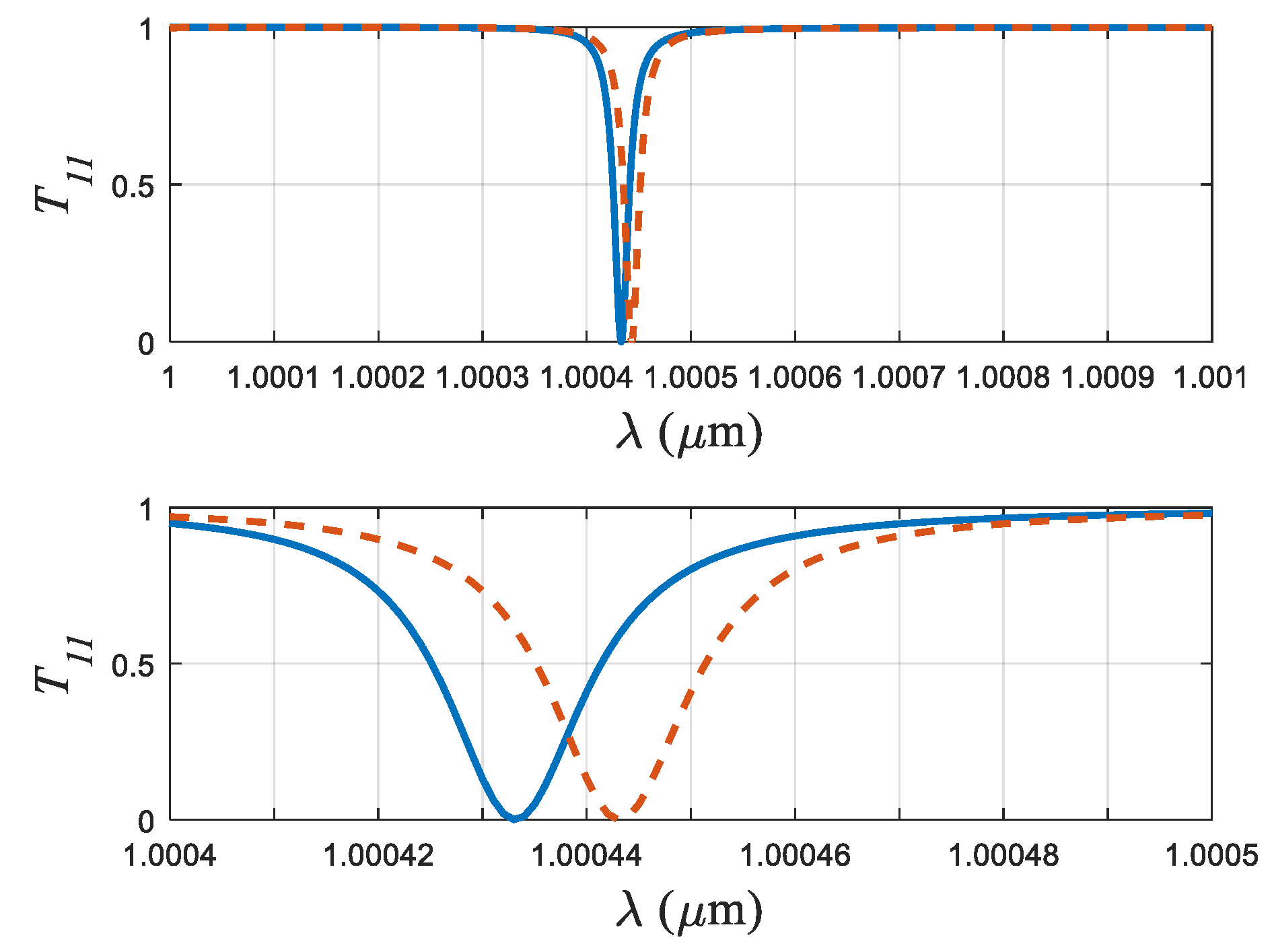
Fig. 3 illustrates the transmission coefficient as a function of wavelength for two distinct waveguide widths, demonstrating the sensor's response to strain. The observed spectral shift resulting from a simulated strain of is clearly resolvable in the vicinity of the resonant wavelength. In this example, the impurity is set at . The overall device sensitivity can be further enhanced by substantially reducing the ratio , effectively positioning the impurity closer to the metallic boundary.
We identify the half-transmission point () as the optimal working point. At this wavelength, the transmission coefficient exhibits a strong linear relationship with respect to both the wavelength and the waveguide width. Placing the device at this point ensures that the change in transmission is directly proportional to the mechanical strain () experienced by the waveguide. In this highly sensitive regime, the transmission is accurately approximated by the linear formula:
where the spectral resolution serves as the large proportionality constant defining the strain sensitivity.
Beyond its primary function as a standalone gauge, the sensor can be readily integrated as a highly sensitive optical element within established differential interferometric systems. This includes configurations such as Michelson, Mach-Zehnder, or Sagnac setups, thereby facilitating the measurement of relative strains between orthogonal directions.
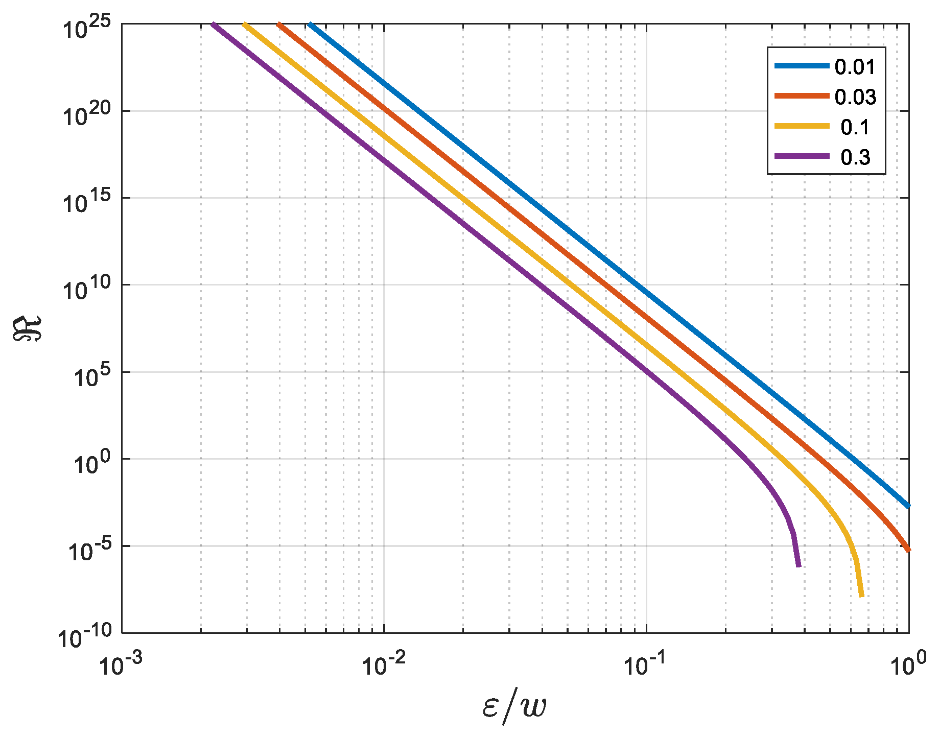
Figure 4.
Spectral resolution vs. proximity to the boundary . The different curves represents different values of (the values shown in the legend). In these cases it was taken that .
Figure 4.
Spectral resolution vs. proximity to the boundary . The different curves represents different values of (the values shown in the legend). In these cases it was taken that .
According to (7), in the regime of a small impurity, i.e., , , in which case
In case and
5.1. Theoretical Resolution and Practical Scaling
Since, in principle, the impurity size can be arbitrarily small and situated arbitrarily close to the boundary, the dimensionless parameter d can be made vanishingly small. Because the spectral resolution scales inversely with the cube of this ratio (), the theoretical resolution is potentially enormous.
It must be emphasized that while the interferometer’s resolution is extremely high, the waveguide length must be larger than its width (w) by a factor proportional to . To illustrate this scaling advantage, consider the goal of measuring strains on the order of : this requires a spectral resolution of . The corresponding required length-to-width ratio would be six orders of magnitude larger than w. Thus, for a width waveguide, the necessary length would only be on the order of a meter. Such a compact device, with a spectral resolution of , could theoretically measure strains down to , assuming current measurement precision (e.g., transmission precision better than 0.1%).
5.2. Construction and Experimental Requirements
In general, the construction imposes few constraints on the local impurity, requiring only that it functions as a subwavelength scatterer whose refractive index exceeds that of the surrounding waveguide medium. This makes the impurity feasible to construct, potentially utilizing existing techniques such as nanofibers [18,19,20,21] situated along the z-direction. However, achieving such high sensitivity experimentally requires stringent controls. The exact implementation must ensure a vibration-free environment, perfectly smooth waveguide boundaries, and the use of low-noise laser sources. The precise engineering methodology required to realize this ultra-sensitive device warrants extended research.
6. Summary and Conclusions
We propose a novel architecture for an ultra-high spectral resolution sensor consisting of a simple, compact metallic-boundary waveguide containing a single point dielectric impurity. A key advantage of this design is its simplicity, as it requires neither complex fine-tuning nor high-finesse mirror systems common in conventional interferometers.
Despite its minimal construction, the device achieves exceptional performance by exploiting Fano resonance, which arises from the quantum-optical interference between the waveguide's continuous modes and a quasi-bound state induced locally by the impurity near the waveguide's cutoff frequency. This mechanism yields a critically sharp spectral feature—a point of perfect reflection (zero transmission)—with an extremely narrow bandwidth.
We demonstrate analytically that the device's spectral resolution () for the case of a small surface defect () can be inversely proportional to the 12th power of the ratio : .
This intrinsic high resolution translates directly into extraordinary sensitivity for measuring mechanical strains. When the sensor is calibrated at the 50% transmission working point (), the change in transmission becomes linearly proportional to the mechanical strain (), with the resolution acting as the proportionality constant: . Our quantitative analysis shows that for a practical geometric ratio of , the theoretical spectral resolution can reach . Consequently, this compact, simple device is capable of measuring mechanical strains smaller than , demonstrating performance comparable to large-scale, high-complexity instruments like gravitational wave detectors.
Appendix A
The solution of the following stationary Schrödinger equation
where represents a point defect, can be approximated using the 2D Green function that solves the equation
In the 2D case it can be formalized using the Hankel function of the first kind [21]
Therefore, the solution can be written as
where is a constant coefficient and is the homogenous incoming solution.
Using the approximation [21]
where is Euler constant, and substituting (A4) in (A1), the coefficient can be derived.
In case (3) is substituted as the point impurity, then
while (8) is substituted as a point impurity then
The two expressions (A5) and (A6) agree when
Appendix B
When (8) and (6) are substituted in (8) the denominator requires solving integrals of the form
. These integrals have a simple form in the regime where , in which case
The usage of (B1) leads to (12)
Appendix C
Following (15)
In the regime ,
Since , the summation can be approximated by an integral. Using the parameter ,
where is a constant, which is very close to 5.
Therefore, finally
References
- Lee, B.H.; Kim, Y.H.; Park, K.S.; Eom, J.B.; Kim, M.J.; Rho, B.S.; Choi, H.Y. Interferometric fiber optic sensors. Sensors (Basel) 2012, 12, 2467–86. [Google Scholar] [CrossRef]
- Pendão, C.; Silva, I. Optical Fiber Sensors and Sensing Networks: Overview of the Main Principles and Applications. Sensors 2022, 22, 7554. [Google Scholar] [CrossRef]
- Wang, L.; Fang, N.; Wu, C.; Qin, H.; Huang, Z. A Fiber Optic PD Sensor Using a Balanced Sagnac Interferometer and an EDFA-Based DOP Tunable Fiber Ring Laser. Sensors 2014, 14, 8398–8422. [Google Scholar] [CrossRef]
- Xie, Y.; Zhang, M.; Dai, D. Design Rule of Mach-Zehnder Interferometer Sensors for Ultra-High Sensitivity. Sensors 2020, 20, 2640. [Google Scholar] [CrossRef] [PubMed]
- Shankland, R.S. Michelson–Morley experiment. American Journal of Physics 1964, 31, 16–35. [Google Scholar] [CrossRef]
- Culshaw, B. The optical fibre Sagnac interferometer: an overview of its principles and applications. Meas. Sci. Technol. 2005, 17, R1–R16. [Google Scholar] [CrossRef]
- Bonopera, M. Fiber-Bragg-Grating-Based Displacement Sensors: Review of Recent Advances. Materials 2022, 15, 5561. [Google Scholar] [CrossRef]
- Ismail, N.; Kores, C.C.; Geskus, D.; Pollnau, M. Fabry-Pérot resonator: spectral line shapes, generic and related Airy distributions, linewidths, finesses, and performance at low or frequency-dependent reflectivity. Opt. Express 2016, 24, 16366–16389. [Google Scholar] [CrossRef]
- Miller, M.C. Dawn of a new astronomy. Nature 2016, 531, 40. [Google Scholar] [CrossRef]
- Cahillane, C.; Mansell, G. Review of the Advanced LIGO Gravitational Wave Observatories Leading to Observing Run Four. Galaxies 2022, 10, 36. [Google Scholar] [CrossRef]
- Miroshnichenko, A.E.; Flach, S.; Kivshar, Y.S. Fano Resonances in Nanoscale Structures. Rev. Mod. Phys. 2010, 82, 2257–2298. [Google Scholar] [CrossRef]
- Limonov, M.; Rybin, M.; Poddubny, A.; et al. Fano resonances in photonics. Nat. Photon 2017, 11, 543–554. [Google Scholar] [CrossRef]
- Granot, E. Total Reflection of Optical Beams by Weakly Oscillating Dielectric Scatterers. Phys. Rev. A 2016, 94, 063828. [Google Scholar] [CrossRef]
- Azbel, M.Y. Variable-range-hopping magnetoresistance. Phys. Rev. B. 1991, 43, 6717. [Google Scholar] [CrossRef]
- Azbel, M.Y. Quantum particle in a random potential: Implications of an exact solution. Phys. Rev. Lett. 1991, 67, 1787–1790. [Google Scholar] [CrossRef]
- Granot, E. Universal conductance reduction in a quantum wire. Europhysics Letters 2004, 68, 860–866. [Google Scholar] [CrossRef]
- Granot, E. Near-threshold-energy conductance of a thin wire. Phys. Rev. B 1999, 60, 10664–10667. [Google Scholar] [CrossRef]
- Wang, X.; Drew, C.; Lee, S.-H.; Senecal, K.J.; Kumar, J.; Samuelson, L.A. Electrospun nanofibrous membranes for highly sensitive optical sensors. Nano Lett. 2002, 2, 1273–1275. [Google Scholar] [CrossRef]
- Yang, Q.; Jiang, X.; Gu, F.; Ma, Z.; Zhang, J.; Tong, L. Polymer micro or nanofibers for optical device applications. J. Appl. Polym. Sci. 2008, 110, 1080–1084. [Google Scholar] [CrossRef]
- Zubia, J.; Arrue, J. Plastic optical fibers: an introduction to their technological processes and applications. Opt. Fiber Technol. 2001, 7, 101–140. [Google Scholar] [CrossRef]
- Zhang, J.; Fang, H.; Wang, P.; Fang, W.; Zhang, L.; Guo, X.; Tong, L. Optical microfiber or nanofiber: a miniature fiber-optic platform for nanophotonics. Photon- Insights 2024, 3, R02. [Google Scholar] [CrossRef]
- Abramowitz, M.; Stegun, I.A. (Eds.) Handbook of Mathematical Functions with Formulas, Graphs, and Mathematical Tables; Dover Publications Inc.: New York, 1965. [Google Scholar]
Figure 1.
System schematic: Metallic waveguide with a dielectric point impurity.
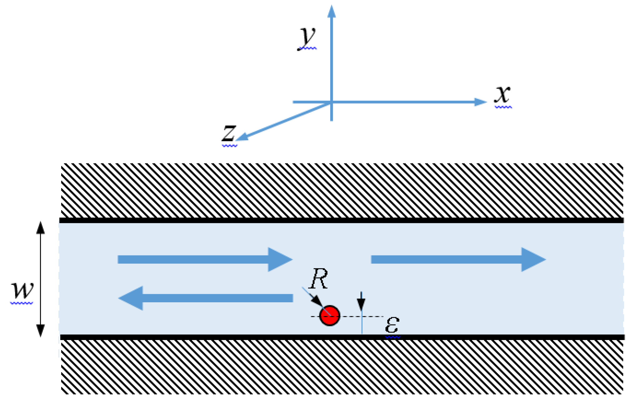
Figure 2.
A contour map of the intensity distribution inside the waveguide at the minimum transmission point. The impurity is marked by a circle. In this scenario .
Figure 2.
A contour map of the intensity distribution inside the waveguide at the minimum transmission point. The impurity is marked by a circle. In this scenario .
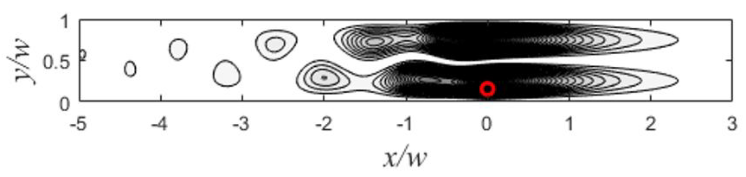
Figure 3.
Transmission coefficient of the first mode as a function of the beam’s wavelength. The dashed curve represent the same system under strain of . The lower panel is the zoom in of the upper one. The parameters are , , , .
Figure 3.
Transmission coefficient of the first mode as a function of the beam’s wavelength. The dashed curve represent the same system under strain of . The lower panel is the zoom in of the upper one. The parameters are , , , .
Disclaimer/Publisher’s Note: The statements, opinions and data contained in all publications are solely those of the individual author(s) and contributor(s) and not of MDPI and/or the editor(s). MDPI and/or the editor(s) disclaim responsibility for any injury to people or property resulting from any ideas, methods, instructions or products referred to in the content. |
© 2025 by the authors. Licensee MDPI, Basel, Switzerland. This article is an open access article distributed under the terms and conditions of the Creative Commons Attribution (CC BY) license (http://creativecommons.org/licenses/by/4.0/).
Copyright: This open access article is published under a Creative Commons CC BY 4.0 license, which permit the free download, distribution, and reuse, provided that the author and preprint are cited in any reuse.


