
Submitted:
05 November 2025
Posted:
05 November 2025
You are already at the latest version
Abstract
Real-time path planning for autonomous Unmanned Aerial Vehicles (UAVs) under strict hardware limitations remains a central challenge in embedded robotics. This study presents a refined Rapidly-Exploring Random Tree (RRT) algorithm implemented within an onboard embedded system based on a 32-bit STM32 microcontroller, demonstrating that real-time autonomous navigation can be achieved under low-power computation constraints. The proposed framework integrates a three-stage process—path pruning, Bézier curve smoothing, and iterative optimization—designed to minimize computational overhead while maintaining flight stability. By leveraging the STM32’s limited 72 MHz ARM Cortex-M3 core and 20 KB SRAM, the system performs all planning stages directly on the microcontroller without external computation. Experimental flight tests verify that the UAV can autonomously generate and follow smooth, collision-free trajectories across static obstacle fields with high tracking accuracy. The results confirm the feasibility of executing a full RRT-based planner on an STM32-class embedded platform, establishing a practical pathway for resource-efficient, onboard UAV autonomy.
Keywords:
onboard embedded system
; STM32 microcontroller
; RRT algorithm
; Bézier curve
; low-power computation
; UAV path planning
1. Introduction
Autonomous Unmanned Aerial Vehicles (UAVs) are flying vehicles capable of executing flight missions without the need for a human pilot. Initially, they were designed for military purposes [1], such as reconnaissance, surveillance, and combat. However, the recent development of low-cost, high-efficiency, and highly mobile UAVs [2] has broadened their use across numerous civil and industrial fields [3], including agricultural irrigation [4], forestry detection [5], ocean monitoring [6], topographic mapping [7], cargo delivery [8], rescue missions [9], and traffic planning [10]. Autonomous UAVs are particularly desirable for replacing humans in high-risk, long-duration, or precision-critical operations.
A UAV system typically consists of three main subsystems: the sensing subsystem, the path planning subsystem, and the execution subsystem. Among them, the path planning module acts as the “brain” of the UAV, enabling autonomous navigation by computing feasible and collision-free routes based on sensor feedback. Given a defined start and goal position, an efficient path planning algorithm determines a trajectory that satisfies mission-specific optimization criteria [11]—for instance, minimizing time, distance, or energy consumption. However, real-time path planning often imposes heavy computational demands on onboard embedded systems, leading to increased power consumption and reduced flight endurance.
Classical and intelligent path planning algorithms have been extensively studied to mitigate this challenge [12]. Early approaches such as the Dijkstra algorithm provided optimal shortest paths but suffered from high computational costs. The A* algorithm improved upon this by introducing heuristic functions for faster convergence; nevertheless, it still required substantial memory and computation time [13,14]. The potential field method introduced by Khatib [14] employed attractive and repulsive forces to navigate around obstacles, and subsequent studies—such as the bacterial potential field [15] and multi-degree potential field methods [16]—sought to overcome the local minimum problem.
In contrast, the Rapidly-Exploring Random Tree (RRT) algorithm offers a more computationally feasible alternative. Originally designed for high-dimensional motion planning, RRT is recognized for its efficient space exploration and low complexity. Yet, its paths are often irregular and discontinuous, which limits their suitability for smooth flight trajectories. The RRT* algorithm proposed by Karaman and Frazzoli [17] addressed part of this issue by improving asymptotic optimality, leading to widespread adoption in robotic and UAV applications [18].
Recent advancements continue to refine RRT-based frameworks for dynamic and resource-constrained systems. For example, Chen et al. [19] developed a dynamic RRT* variant capable of real-time replanning in cluttered urban environments, while Kumar and Singh [20] integrated Particle Swarm Optimization (PSO) with RRT to improve energy efficiency in long-range UAV missions. Despite these innovations, most implementations assume powerful onboard processors or external computation units, which are often impractical for lightweight UAVs using low-power embedded hardware.
To bridge this technological gap, this study presents the design and implementation of an improved RRT algorithm on an STM32-based onboard embedded system, emphasizing low-power computation and real-time feasibility. Unlike simulation-only approaches, our work performs all path planning tasks—including path pruning, Bézier curve smoothing, and iterative optimization—directly on a 32-bit STM32 microcontroller. To manage computational constraints, the UAV’s navigation task is formulated as a 2.5D path planning problem, where trajectory generation occurs on the horizontal plane with altitude stabilized via the flight controller’s barometric feedback. This simplification enables efficient onboard computation without sacrificing trajectory accuracy. The subsequent sections detail the system implementation, algorithmic optimization, and in-flight validation results, confirming the viability of executing a refined RRT-based path planner entirely within a constrained embedded UAV platform.
This study aims to bridge the gap between theoretical path planning algorithms and their practical implementation on computationally limited onboard embedded systems. The primary contribution of this work is not the introduction of a novel algorithm, but the successful adaptation, optimization, and in-flight validation of an enhanced RRT-based framework implemented directly on a 32-bit STM32 microcontroller. To effectively balance computational complexity, memory footprint, and power efficiency, the navigation problem is formulated as a 2.5D path planning model, where trajectory generation is conducted on a two-dimensional plane at a fixed altitude. Altitude stability is independently maintained by the flight controller’s onboard barometer, enabling the computationally intensive RRT–Bézier hybrid planner to focus exclusively on the XY-plane. The following sections describe the detailed algorithmic design, onboard optimization strategies for low-power computation, and experimental validation results that confirm the feasibility of achieving autonomous flight using a constrained STM32-class embedded platform.
This architectural choice intentionally prioritizes computational stability and energy efficiency over sub-second responsiveness. By constraining the planner to a 2.5D formulation and accepting a planning latency of approximately 958 ms per cycle, the system achieves a practical balance between low-power embedded execution and long-endurance flight in static ground-obstacle environments. This represents a deliberate engineering trade-off rather than a limitation of the RRT algorithm itself. The following sections describe the detailed algorithmic design, onboard optimization strategies for low-power computation, and experimental validation results that confirm the feasibility of achieving autonomous flight using a constrained STM32-class embedded platform.
2. An Improved RRT Algorithm
Rapidly-Exploring Random Trees (RRT) in a matrix space (S) plans a route from a starting point (Sstart, Sstart ⊂ S) to a destination (Sdest, Sdest ⊂ S) by exploring the free space (Sfree, Sfree ⊂ S), and avoids obstacles (Sobst, Sobst ⊂ S). Both Sstart and Sdest are points in this three-dimensional space. The RRT algorithm starts with Sstart and generates a random sampling point (Srand, Srand ⊂ S) in the matrix space to search for the node which is nearest the Srand in the tree as Snear (Snear, Snear ⊂ S).
Snear then extends a shortest distance based on Euclidean distance toward Srand as a new node Snew and ensures the distance is limited in every expansion. When Snear ⊂ Sfree and does not intersect with Sobst, Snew will be added into the tree and repeating the process until it reaches the destination. Figure 1 illustrates a save path generated by RRT algorithm. Because of the randomness of the path, many redundant turning points will be produced during the process, which could lead to inefficient path planning.
2.1. Pruning and Obstacle Detection
Since the paths generated by the RRT algorithm are often zigzag and difficult for UAVs to execute, path pruning is thus essential. The pruning process is illustrated in Figure 2. By removing unnecessary points, a collision-free path can be produced. Starting with the initial point, three consecutive points are chosen for pruning. If the first and third nodes can be connected without colliding with any obstacles, the second node is redundant and will be removed. Otherwise, the second node is retained. This process continues until the shortest path is achieved. As illustrated in Figure 2(a), when considering points P1, P2, and P3, connecting P1 and P3 results in a collision with the obstacle, so P2 must be retained. However, when considering points P3, P4, and P5, connecting P3 and P5 results in no collision, making P4 redundant and eligible for pruning. During the pruning process, removing redundant nodes shall generate a more efficient path as shown in Figure 2(b).
In path planning, it is necessary to detect collisions to determine whether the path between two points intersects with any obstacles. Polygonal modeling for collision detection is usually complex, time-consuming, and computationally intensive. Simplifying the geometry of obstacles can improve efficiency. The boundaries of obstacles can be set as rectangular by a distance ds, where ds is half of the UAV’s width as shown in Figure 3(a). During collision checking, if both points are on the same side of the obstacle as shown in Figure 3(b), the path is safe. Otherwise, further verification is required by the conditions:
where Aco1 and Aco3 are the angles between P1 and the edge of obstacle, and Acp is the angle of the path between two check points. Equation (1) indicate P1 is on the left side of the obstacle, and Equation (2) indicate P3 is on the right side of the obstacle as shown in Figure 3(c). This detection ensures any point on the path will not collide with the obstacles. After pruning and obstacle detection, the number of nodes decrease significantly by about 99%. This pruning not only shortens the path length but also reduces the number of turning points.
(Acp ≤ Aco1 )∪(Aco3 ≤ Acp )
Aco1 ≤ Acp ≤ Aco3
2.2. Smoothing and Optimization
After pruning, a more concise path is obtained as shown in Figure 2(b). However, the path is not continuously differentiable, thus may reduce the navigation efficiency. B´ezier curves are applied to make the path continuously differentiable. One advantage of B´ezier curves is their low computational cost, allowing UAVs to avoid obstacles while maintaining kinematic feasibility. A B´ezier curve requires only three control points to generate a transition curve that connects two line-segments [21]. B´ezier curves have also been used for collision-free path planning in land changes [22] and vehicle tracking [23]. The equation of a quadratic B´ezier curve is
where Pi+1 is the control points of Bézier curve and is
A quadratic Bézier curve (n = 2) requires three control points. To define these, set the first control point at the turning point, and move forward and backward along the path for a specific distance to determine the other two control points. This specific distance is based on the golden ratio 0.382 (by Fibonacci number) to the length of the line segment. Two sets of control points are shown in Figure 4(a), and the resulting smooth Bézier curve is obtained after calculation as shown in Figure 4(b). Loworder Bézier curve offers excellent efficiency with minimal computational cost.
The selection of the 0.382 ratio, instead of a symmetric 0.5 midpoint, is not arbitrary. This value corresponds to the golden section point, which minimizes curvature variation along the quadratic Bézier transition, thereby reducing instantaneous jerk during UAV turning maneuvers. Empirical tuning further confirmed that the 0.382 ratio provides smoother heading changes and maintains a safer lateral clearance from nearby obstacles compared to equal-distance control placement. Consequently, the low-order Bézier smoothing achieved both computational simplicity and improved kinematic feasibility for embedded flight control.
The randomness of the RRT algorithm allows it to find the paths in a complex space, and there are often multiple possible paths. The path could extend upward or downward as shown in Figure 5(a, where the downward path is clearly inefficient. Therefore, it is crucial to discover the nearest or shortest path. By repeating the path planning process, the shortest path can be identified. Table 1 lists the success rate of finding the shortest path and the computation time when repeating the path planning process 1, 5, and 10 times. The success rate for a single execution is 56%, requiring 0.09 second. The success rate for 5 repeated path planning is 74% with computation time of 0.42 second. For 10 path planning, the success rate increases to 96%, requiring 0.9 second. These results indicate that increasing the number of repeated planning improves the success rate of finding the shortest path. With advancements in chip technology (STM32) as described in the coming section, this result is acceptable. Figure 5(b) shows the outcome after repeating the planning process 10 times the shortest path for autonomous UAV can be found.
The results show that after pruning and optimization as illustrated in Figure 5(b), the path length decreases approximately by half, significantly increasing flight efficiency. Path length can be viewed as an indicator of the effectiveness of path planning.
The data indicates that the original path length generated by the RRT algorithm is 1043 units. After pruning, the path length is reduced to 776 units, a 34% decrease. Following curve fitting, the path length is further reduced to 583 units, another 33% reduction compared to the pruned path. Figure 6 illustrates the paths generated by the improved RRT algorithm in environments with various obstacles. It is evident that this improved algorithm provides an efficient and safe path for UAVs.
3. Experimental Verification of Autonomous Flight
3.1. System Hardware and Platform
To verify the effectiveness of the path-planning framework, we conducted flight experiments using a UAV equipped with an onboard STM32 microcontroller (Figure 7). In this study, the final validation is based on planning executed entirely on the onboard STM32, while data monitoring and bidirectional telemetry were still handled via the ground station. A digital transmission module facilitated communication between the UAV and the ground station, enabling real-time status reporting for supervision and safety. The UAV was equipped with a GPS module and a barometer; GPS provided position feedback for waypoint tracking, and the barometer maintained altitude stability, with both signals relayed to the ground station for logging and mission oversight.
3.2. Mission Scenario and 2.5D Flight Strategy
The flight plan is shown in Figure 8 with the starting point and destination indicated. The STM32 microcontroller equipped with an ARM Cortex-M3 running at 72MHz is capable of efficiently handling the computational tasks of the improved RRT algorithm. Its computational speed is 1.25 DMIPS/MHz, and the power consumption is approximately 20-40 mA at full speed (72 MHz) with the operating voltage 3.3V. Compared with other microcontrollers, it maintains a low power consumption, making it attractive for requiring long term operation. This makes STM32 an ideal choice for a mission planning system with both excellent computing speed and energy efficiency.
The STM32 microcontroller equipped with an ARM Cortex-M3 running at 72MHz is capable of efficiently handling the computational tasks of the improved RRT algorithm. Its computational speed is 1.25 DMIPS/MHz, and the power consumption is approximately 20-40 mA at full speed (72 MHz) with the operating voltage 3.3V. Compared with other microcontrollers, it maintains a low power consumption, making it attractive for requiring long term operation. This makes STM32 an ideal choice for a mission planning system with both excellent computing speed and energy efficiency. In addition, the STM32 microcontroller offers extensive peripherals, including USART, SPI, I2C, USB, ADC (Analog-to-Digital Converter), and DAC (Digital-to-Analog Converter). These peripherals allow the STM32 to interface with a wide range of sensors, such as digital transmission modules, GPS modules, and barometers, allowing it to detect the environment and communicate with the drone. Lower power efficiency and extensive sensor integration for maintaining both performance and stability over long-duration missions, making the STM32 a strong foundation for autonomous control in UAVs and other embedded systems. After the experiment, the improved RRT algorithm proved effective in planning an optimal path without requiring extensive computational resources. This allowed the UAV to follow the planned path autonomously and reach the destination without any collisions.
In this experiment, all obstacles were static ground-based objects. To simplify computational complexity and reduce the processing burden of the algorithm on the microcontroller, the UAV was set to fly at a safe, fixed altitude, ensuring that it could directly pass over ground obstacles without handling altitude variations in a fully three-dimensional environment. The flight altitude was regulated by the onboard baroSmoothing and Optimizationmeter through closed-loop control, thereby maintaining stability and transforming the overall planning task into a 2.5D path planning problem—that is, path searching and obstacle avoidance conducted on a two-dimensional horizontal plane at a fixed altitude. This design is shown in Figure 9 allows the resource-constrained STM32 microcontroller to focus exclusively on real-time path planning in the XY plane, improving efficiency and avoiding additional computational overhead caused by altitude changes.
3.3. Navigation and Control Architecture
This study adopts a hierarchical architecture for navigation and control, as illustrated in Figure 10. In the upper layer, path planning is performed either by the ground station or the onboard STM32 microcontroller, which computes and generates a sequence of GPS waypoints. These waypoints are then transmitted to the UAV’s lower-layer flight controller, such as an open-source autopilot based on ArduPilot or PX4. The lower-layer controller is responsible for executing position control; that is, it calculates the error between the current GPS position and the target waypoint, and automatically outputs motor commands to guide the UAV toward the designated waypoint. The core contribution of this study lies in the intelligent generation of waypoints at the upper layer rather than in the design of the lower-layer controller.
3.4. Onboard Implementation Challenges and Optimizations
Porting a computationally intensive algorithm like the refined RRT from a PC environment to a resource-constrained microcontroller such as the STM32F103C8T6 presents significant technical challenges. The primary constraints are the limited 20 KB of SRAM, 64 KB of Flash memory, and the 72 MHz ARM Cortex-M3 processor, which lacks a dedicated Floating-Point Unit (FPU).To address these limitations, several key optimizations were implemented.
First, to manage the memory footprint of the growing RRT tree, a statically allocated node pool was used instead of dynamic memory allocation (e.g.; malloc).This approach prevents memory fragmentation and ensures predictable memory usage, which is critical for the stability of an embedded system. The maximum number of nodes was capped at a value empirically determined to be sufficient for the given map complexity while fitting within the available SRAM. Second, to mitigate the performance impact of floating-point arithmetic, critical calculations in the distance and collision-checking functions were carefully reviewed. Where possible, comparisons were performed on squared Euclidean distances to avoid costly square root operations. Furthermore, the firmware was compiled using high-level compiler optimizations (-O3) to maximize code efficiency and reduce the instruction cycle count. These targeted optimizations were essential to ensure the entire three-stage planning algorithm could execute successfully within the hardware's limitations.
In this implementation, all RRT nodes were allocated from a statically defined memory pool to avoid fragmentation within the limited 20 KB SRAM of the STM32F103C8T6. Each node stored its Cartesian coordinates (x, y), parent index, and cost value in 16-bit precision, resulting in a memory usage of approximately 12 bytes per node. Considering additional control variables and system buffers, the total usable memory for RRT expansion was limited to roughly 18 KB, which corresponds to a maximum node capacity of about Nₘₐₓ = 1500 nodes. This quantitative constraint directly reflects the trade-off between algorithmic flexibility and real-time stability under the STM32’s hardware resources. When the node pool reaches Nₘₐₓ, the tree expansion halts automatically to ensure deterministic memory behavior throughout execution.
Second, to mitigate the performance impact of floating-point arithmetic, critical calculations in the distance and collision-checking functions were carefully reviewed. Where possible, comparisons were performed on squared Euclidean distances to avoid costly square-root operations. Furthermore, the firmware was compiled using high-level compiler optimizations (-O3) to maximize code efficiency and reduce the instruction cycle count. These targeted optimizations were essential to ensure that the entire three-stage planning algorithm could execute successfully within the hardware’s limitations.
4. Results and Discussion
This section presents the quantitative results from the in-flight validation experiments. The performance of the onboard planner is evaluated in terms of trajectory tracking accuracy, computational efficiency on the STM32 microcontroller, and a comparative analysis of its power consumption and positioning within the broader landscape of path planning algorithms.
4.1. Flight Trajectory Validation
To validate the system's real-world effectiveness, the planned path generated by the STM32 was executed by the UAV, and the actual flight trajectory was recorded via GPS telemetry. Figure 11 provides a visual comparison between the optimized path computed onboard and the actual trajectory flown by the UAV. The figure clearly shows that the UAV closely followed the planned route, with only minor deviations attributed to wind disturbances and waypoint-tracking latency. This confirms the robustness of the proposed planner in maintaining trajectory accuracy under real-world flight conditions.
A quantitative analysis of the flight performance is presented in Table 2. The experiment was repeated five times to ensure statistical reliability, and the presented values are the averages of these runs. The results show a high degree of correspondence between the planned and executed paths, with an average tracking error of only 1.25 meters.
The discussion of these results reveals several insights. The slight increase in actual path length and flight time can be attributed to external factors such as wind gusts and the inherent limitations of the lower-layer flight controller's PID loop in perfectly tracking waypoints. The average tracking error of 1.25 meters is well within the expected tolerance for a standard civilian GPS module and confirms that the generated path is not only collision-free in theory but also safely executable in practice.
4.2. Onboard Computational Performance
A key claim of this study is the real-time capability of the planner on the STM32 platform. To substantiate this, the execution time of each stage of the algorithm was measured directly on the microcontroller using its internal timers. Table 3 details the average processing time required for a complete planning cycle, based on 10 optimization runs as described in Section 2.2.
The total planning time of just under one second is a critical result. While this may not be sufficient for highly dynamic environments requiring sub-second replanning, it is perfectly acceptable for pre-flight mission planning in static or semi-static environments, which was the target application for this study. This performance benchmark validates that the STM32 microcontroller, despite its constraints, possesses adequate computational power for this complex task, directly addressing the critique of insufficient computational analysis.
4.3. Onboard Computational Performance
The choice of the STM32 was motivated by its low power consumption. During the planning phase (full computational load at 72 MHz), the current drawn by the STM32F103C8T6 was measured to be approximately 30 mA at a supply voltage of 3.3V, resulting in a power consumption of about 99 mW. This is significantly lower than more powerful single-board computers like a Raspberry Pi, which can consume several watts, making our approach highly suitable for battery-powered UAVs where endurance is paramount.
To contextualize the contribution of this work, Table 4 provides a comparative analysis against other state-of-the-art RRT-based methods based on literature. This comparison highlights the trade-offs between algorithmic optimality, environmental adaptability, and hardware feasibility.
This analysis makes the contribution of our paper clear: while other methods achieve higher levels of path optimality or adaptability, they do so at the cost of computational resources that make them unsuitable for direct implementation on low-cost microcontrollers. Our work fills a crucial gap by demonstrating a complete, validated solution that prioritizes resource efficiency and practical embeddability, thereby confirming the viability of advanced path planning on hardware platforms that are accessible and widely used in the UAV industry.

Table 5.
Consolidated performance summary and future optimization direction.
| Parameter Category | Current Value / Observation | Optimization Target / Future Direction |
|---|---|---|
| RRT Tree Generation Time | 855 ms (≈89 % of total latency) | Reduce via incremental tree reuse or hierarchical sampling |
| Total Planning Cycle | 958 ms | Aim for < 500 ms through algorithmic refinement and hardware acceleration |
| Energy Consumption | ≈ 99 mW at 72 MHz | Maintain low-power operation while supporting real-time LiDAR integration |
| Environmental Perception | Predefined static map | Integrate LiDAR and camera modules for real-time mapping and obstacle avoidance |
| System Behavior | Deliberative (pre-mission planning) | Transform into Reactive (onboard replanning and dynamic response) |
5. Conclusions
This paper has successfully demonstrated the practical implementation and in-flight validation of a refined RRT-based path-planning framework on a UAV platform equipped with a resource-constrained STM32 microcontroller. The primary contribution of this work is not the development of a novel algorithm but rather a comprehensive engineering case study that confirms the feasibility of executing a sophisticated multistage planning process—including path pruning, Bézier-curve smoothing, and iterative optimization—entirely within an onboard embedded system.
Our experimental results provide clear evidence that the system is effective in real-world conditions. The UAV autonomously computed and accurately followed collision-free trajectories in an environment with static ground obstacles. By framing the navigation task as a 2.5D path-planning problem, in which trajectory generation is performed on a two-dimensional plane while altitude is maintained by an onboard barometer, the computational workload was effectively contained within the low-power STM32 processor. The resulting planning latency of approximately 958 ms per cycle represents an intentional balance between computational stability, energy efficiency, and operational endurance. This latency is a deliberate engineering trade-off designed for low-power, long-duration missions rather than a limitation of the RRT algorithm itself. Consequently, the framework demonstrates that even with constrained hardware resources, a high degree of autonomous capability can be achieved.
Looking forward, the current system serves as a robust foundation for future enhancements. Its present limitation lies in the reliance on a predefined static map. The next logical step is to integrate real-time environmental-perception sensors, such as cameras or LiDAR, to enable dynamic obstacle detection and avoidance. This evolution would transition the current planner from a purely deliberative framework into a reactive and adaptive onboard system, thereby extending its applicability to more complex and uncertain operational scenarios while maintaining its low-power and high-endurance design philosophy.
Future Work Perspective
Despite the overall success of the proposed framework, the RRT tree-generation stage, which accounts for approximately 855 ms of the total 958 ms planning latency, remains the dominant computational bottleneck. Future work will therefore focus on optimizing this stage through techniques such as incremental tree reuse, hierarchical sampling, or hardware-assisted acceleration. Additionally, integrating high-resolution LiDAR and complementary perception modules will allow the system to perceive and model its surroundings in real time, enabling onboard replanning and obstacle avoidance without reliance on predefined maps. This integration will effectively transform the proposed STM32-based planner from a deliberative pre-mission system into a fully reactive autonomous framework capable of dynamic adaptation in changing environments. Such advancement would further demonstrate the potential of embedded, low-power computation as a viable foundation for next-generation UAV autonomy.
Author Contributions
S. E. Tsai1* (Shang-En Tsai) is an Associate Professor in the Department of Computer Science and he was in charge of conceptualization, methodology, validation, formal analysis, project administration, writing – original draft. S. M. Yang2 (Shih-Ming Yang) is a Distinguished Professor in the Department of Aeronautics and Astronautics, where he developed the improved RRT algorithm and formal analysis, writing – review & editing. W. C. Sun3 (Wei-Cheng Sun) is a Research Assistant in Tsai’s lab and he implemented the firmware of the flight controller for autonomous flight and data curation.
Funding
This work was supported by the National Science and Technology Council (NSTC), Taiwan, under Grant No. 114-2625-M-309-001.
Data Availability Statement
The original contributions presented in this study are included in the article. Further inquiries can be directed to the corresponding author.
Conflicts of Interest
The authors declare no conflict of interest.
References
- Huang, Z.; Gao, Y.; Guo, J.; Qian, C.; Chen, Q. : An adaptive bidirectional quick optimal rapidly-exploring random tree algorithm for path planning. Engineering Applications of Artificial Intelligence 2024, 135, 108776. [Google Scholar] [CrossRef]
- Telli, K.; Kraa, O.; Himeur, Y.; Ouamane, A.; Boumehraz, M.; Atalla, S.; Mansoor, W. : A comprehensive review of recent research trends on unmanned aerial vehicles (UAVs). Systems 2023, 11, 400. [Google Scholar] [CrossRef]
- Kim, J.; Kim, S.; Ju, C.; Son, H.R. : Unmanned aerial vehicles in agriculture: A review of perspective of platform, control, and applications. IEEE Access 2019, 7, 105100–105115. [Google Scholar] [CrossRef]
- Iglhaut, J.; Cabo, C.; Puliti, S.; Piermattei, L.; O’Connor, J.; Rosette, J. : Structure from motion photogrammetry in forestry: A review. Current Forestry Reports 2019, 5, 155–168. [Google Scholar] [CrossRef]
- Yang, Z. Y.; Yu, X. Y.; Dedman, S.; Rosso, M.; Zhu, J. M.; Yang, J. Q.; Xia, Y. X.; Tian, Y. C.; Zhang, G. P.; Wang, J. Z. : UAV remote sensing applications in marine monitoring: Knowledge visualization and review. Science of the Total Environment 2022, 838, 155939. [Google Scholar] [CrossRef] [PubMed]
- Nordin, Z.; Salleh, A. M. : Application of unmanned aerial vehicle (UAV) in terrain mapping: Systematic literature review. International Journal of Sustainable Construction Engineering and Technology 2022, 13, 216–233. [Google Scholar] [CrossRef]
- Li, X. P.; Tupayachi, J.; Sharmin, A.; Ferguson, M. M. : Drone-aided delivery methods, challenge, and the future: A methodological review. Drones 2023, 7, 191. [Google Scholar] [CrossRef]
- Lyu, M.; Zhao, Y. B.; Huang, C.; Huang, H.L. : Unmanned aerial vehicles for search and rescue: A survey. Remote Sensing 2023, 15, 3266. [Google Scholar] [CrossRef]
- Bisio, I.; Garibotto, C.; Haleem, H.; Lavagetto, F.; Sciarrone, A. : A systematic review of drone-based road traffic monitoring system. IEEE Access 2022, 10, 101537–101555. [Google Scholar] [CrossRef]
- Gugan, G.; Haque, A. : Path planning for autonomous drones: Challenges and future directions. Drones 2023, 7, 169. [Google Scholar] [CrossRef]
- Liu, L. X.; Wang, X.; Yang, X.; Liu, H. J.; Li, J. P.; Wang, P. F. : Path planning techniques for mobile robots: Review and prospect. Expert Systems with Applications 2023, 227, 120254. [Google Scholar] [CrossRef]
- Singh, Y.; Sharma, S.; Sutton, R.; Hatton, D.; Khan, A. : A constrained A* approach towards optimal path planning for an unmanned surface vehicle in a maritime environment containing dynamic obstacles and ocean currents. Ocean Engineering 2018, 169, 187–201. [Google Scholar] [CrossRef]
- Cheng, C.; Sha, Q.; He, B.; Li, G. L. : Path planning and obstacle avoidance for AUV: A review. Ocean Engineering 2021, 235. [Google Scholar] [CrossRef]
- Khatib, O. : Real-time obstacle avoidance for manipulators and mobile robots. In: Cox, I. J.; Wilfong, G. T. (eds.) Autonomous Robot Vehicles 1986, 396–404.
- Orozco-Rosas, U.; Montiel, O.; Sepúlveda, R. “Parallel Bacterial Potential Field Algorithm for Path Planning in Mobile Robots: A GPU Implementation. In Fuzzy Logic Augmentation of Neural and Optimization Algorithms: Theoretical Aspects and Real Applications; Castillo, O., Melin, P., Kacprzyk, J., Eds.; Studies in Computational Intelligence; Springer: Cham, Switzerland, 2018; Volume 749, pp. 207–222. [Google Scholar]
- Ge, H. Q.; Chen, G. B.; Xu, G. : Multi-AUV cooperative target hunting based on improved potential field in a surface-water environment. Applied Sciences 2018, 8, 973. [Google Scholar] [CrossRef]
- H. J. Zhang, Y. K. Wang, J. Zheng, and J. Z. Yu, "Path planning of industrial robot based on improved RRT algorithm in complex environments. IEEE Access 2018, 6, pp.
- Karaman, S.; Frazzoli, E. : Sampling-based algorithms for optimal motion planning. The International Journal of Robotics Research 2011, 30, 846–894. [Google Scholar] [CrossRef]
- Chen, L.; et al. : A dynamic RRT algorithm for real-time obstacle avoidance in cluttered urban environments. Drones 2024, 8, 112. [Google Scholar]
- Kumar, A.; Singh, R. : Hybrid PSO-RRT algorithm for energy-efficient path planning in long-range UAV missions. Drones 2023, 7, 564. [Google Scholar]
- Ravankar, A.; Ravankar, A. A.; Kobayashi, Y.; Hoshino, Y.; Peng, C. C. : Path smoothing techniques in robot navigation: State-of-the-art and current and future challenges. Sensors 2018, 18, 3170. [Google Scholar] [CrossRef]
- Yang, S. M.; Lin, Y. A. : Development of an improved rapidly-exploring random trees algorithm for static obstacle avoidance in autonomous vehicles. Sensors 2021, 21, 2244. [Google Scholar] [CrossRef]
- Li, H. L.; Luo, Y. T.; Wu, J. : Collision-free path planning for intelligent vehicles based on Bézier curve. IEEE Access 2019, 7, 123334–123340. [Google Scholar] [CrossRef]
- Jermyn, J.; Roberts, R. Path planning algorithms: an evaluation of five rapidly exploring random tree methods. Proc. 34th Florida Conf. on Recent Advances in Robotics 2021, Pensacola, FL, USA, 19–21 May.
- Chu, Y.; Chen, Q.; Yan, X. An overview and comparison of traditional motion planning based on rapidly exploring random trees. Sensors 2025, 25, 2067. [Google Scholar] [CrossRef] [PubMed]
Figure 1.
The traditional RRT algorithm in path planning from the start to the destination.
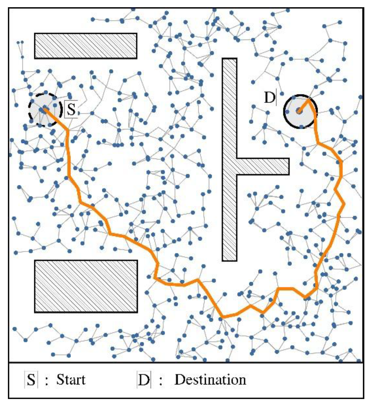
Figure 2.
(a) Illustration of path pruning where point P2 is kept and P4 is redundant and (b) the path after pruning-for UAV path planning.
Figure 2.
(a) Illustration of path pruning where point P2 is kept and P4 is redundant and (b) the path after pruning-for UAV path planning.
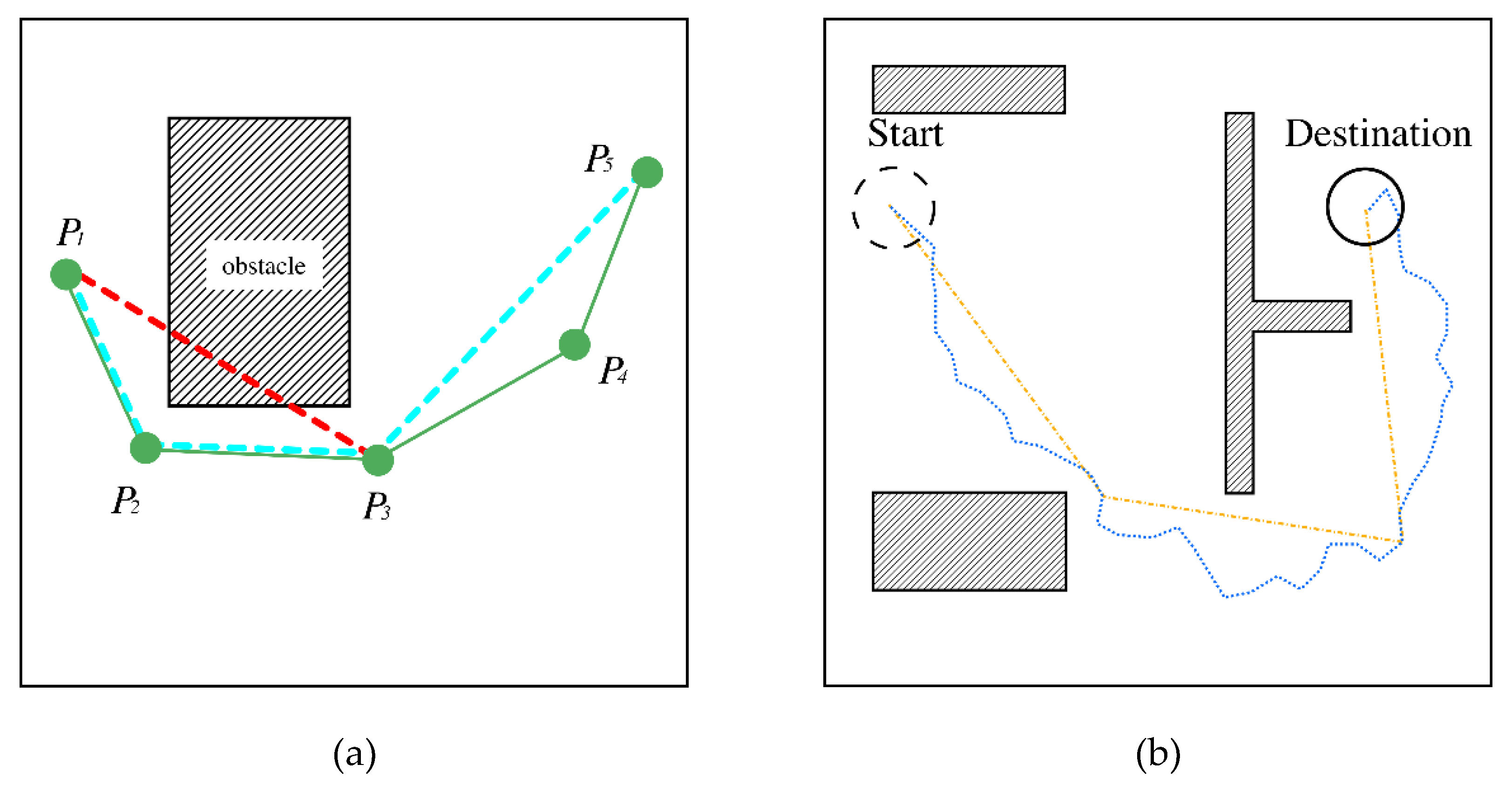
Figure 3.
(a) The obstacle defined by a rectangle boundary safety ds, (b) two points at the same side indicating the safe path, and (c) two points off side, indicating collision check with angle Aco1 and Aco3.
Figure 3.
(a) The obstacle defined by a rectangle boundary safety ds, (b) two points at the same side indicating the safe path, and (c) two points off side, indicating collision check with angle Aco1 and Aco3.
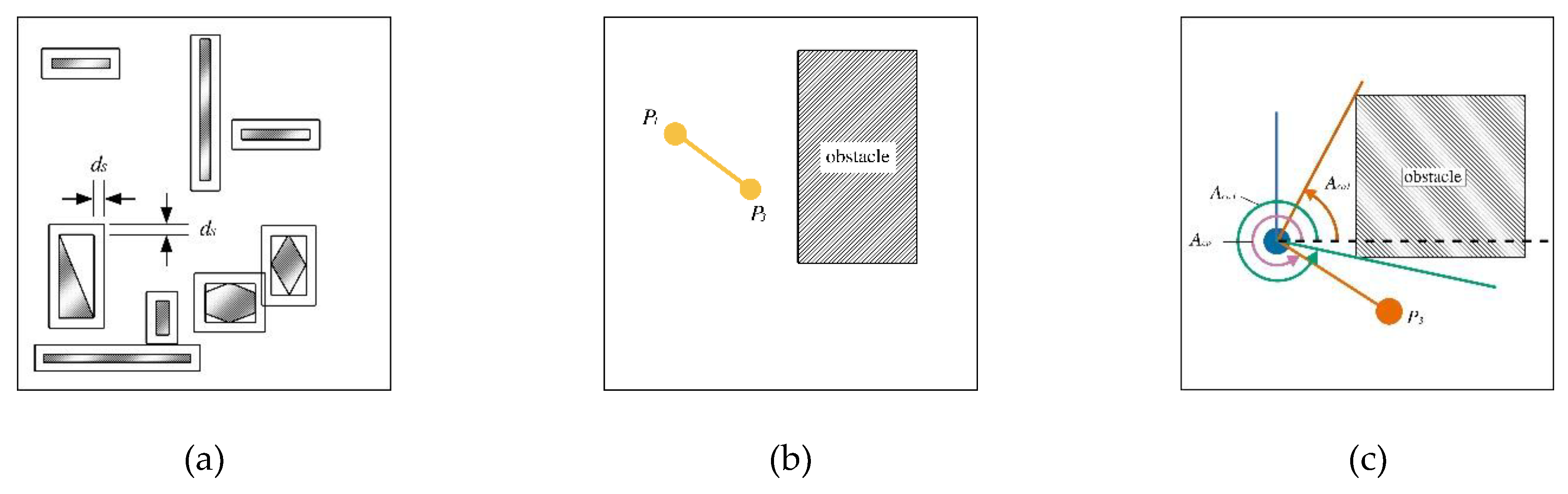
Figure 4.
(a) The two control points by golden ratio for turning points in path smoothing and (b) the path after pruning and smoothing.
Figure 4.
(a) The two control points by golden ratio for turning points in path smoothing and (b) the path after pruning and smoothing.
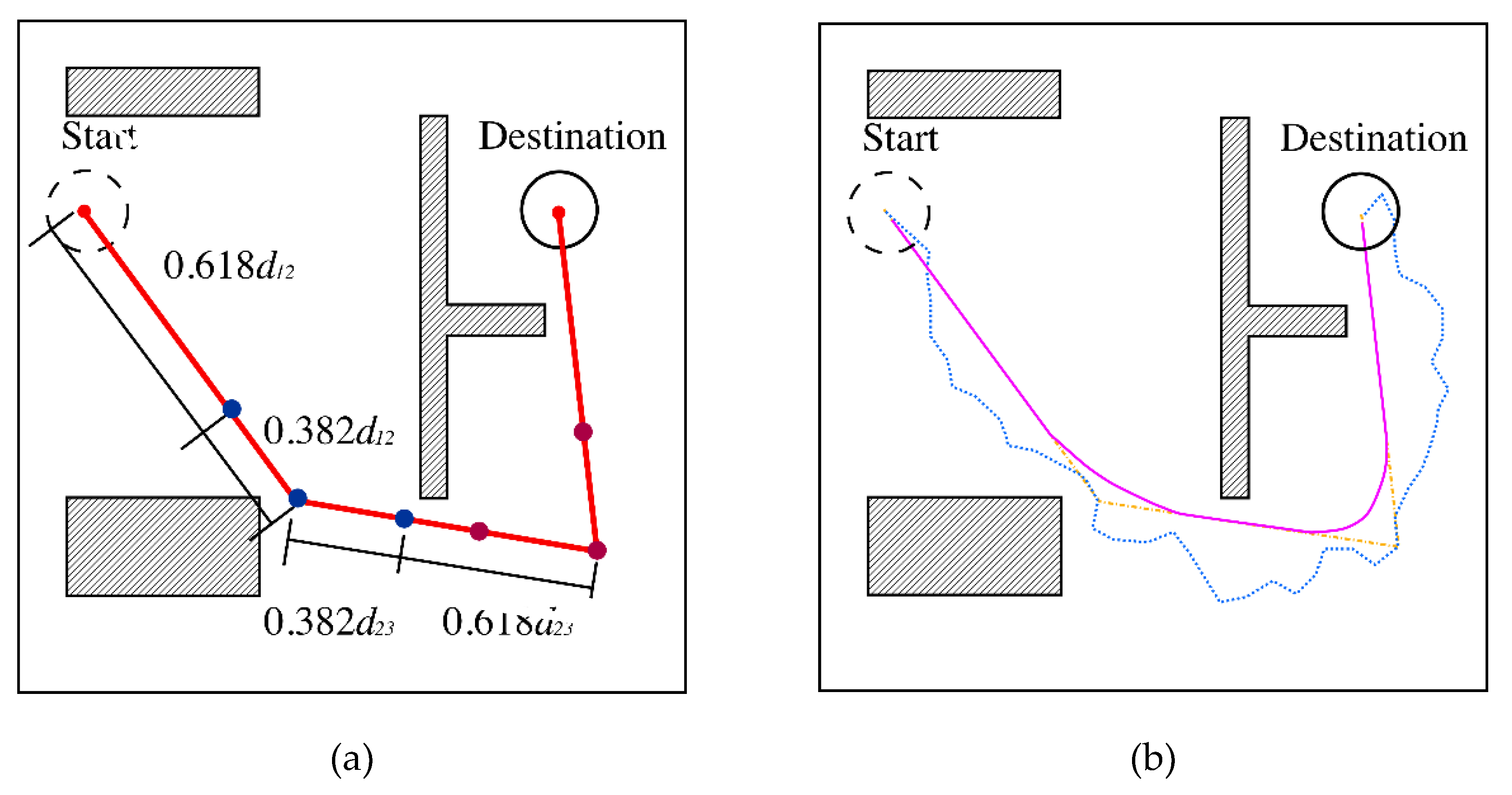
Figure 5.
(a) The result of 10 path planning and (b) by the improved algorithm (solid lines) vs. the RRT algorithm (dash line) the shortest path.
Figure 5.
(a) The result of 10 path planning and (b) by the improved algorithm (solid lines) vs. the RRT algorithm (dash line) the shortest path.
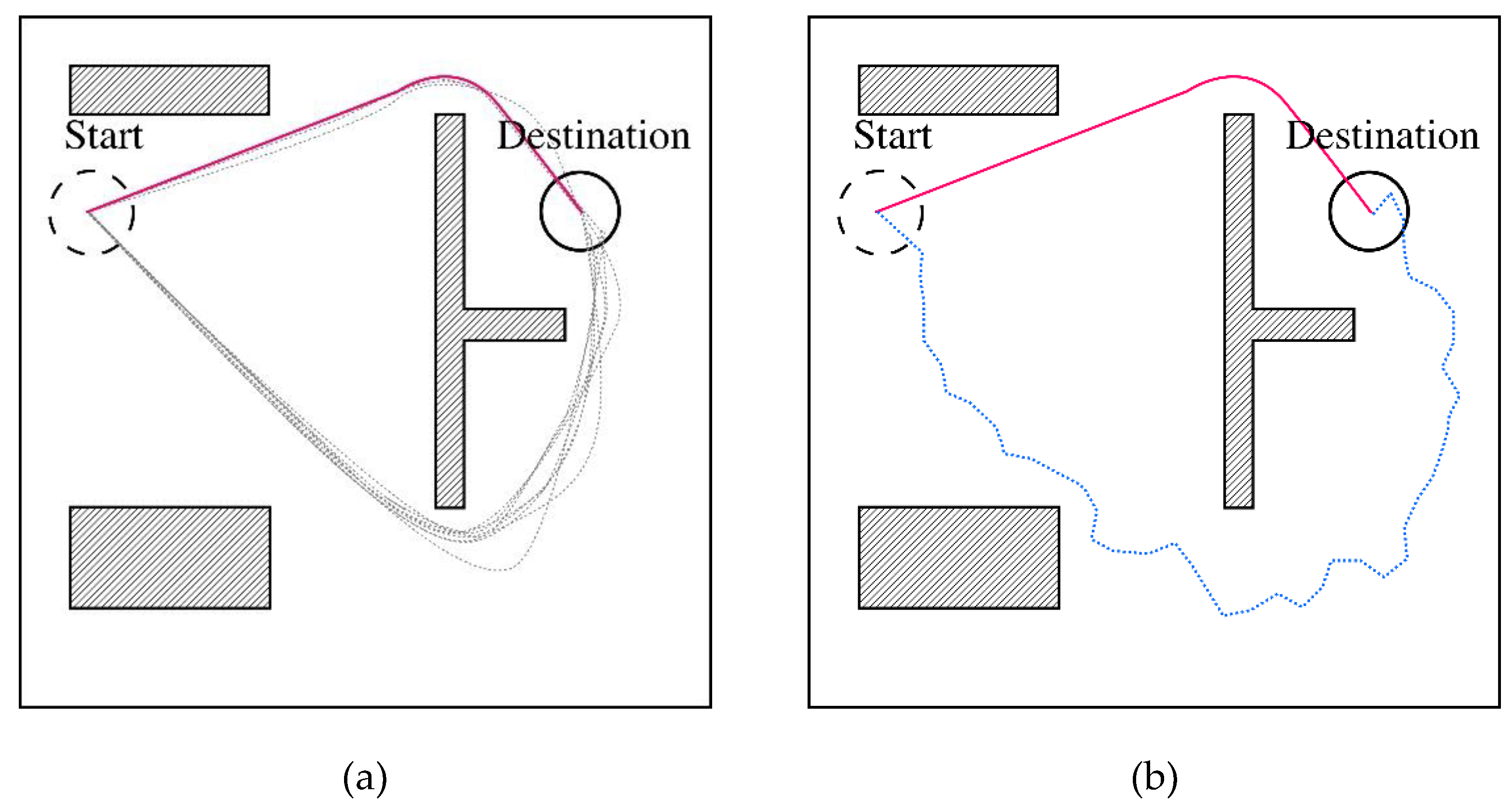
Figure 6.
The result of path planning in different configurations of obstacle.
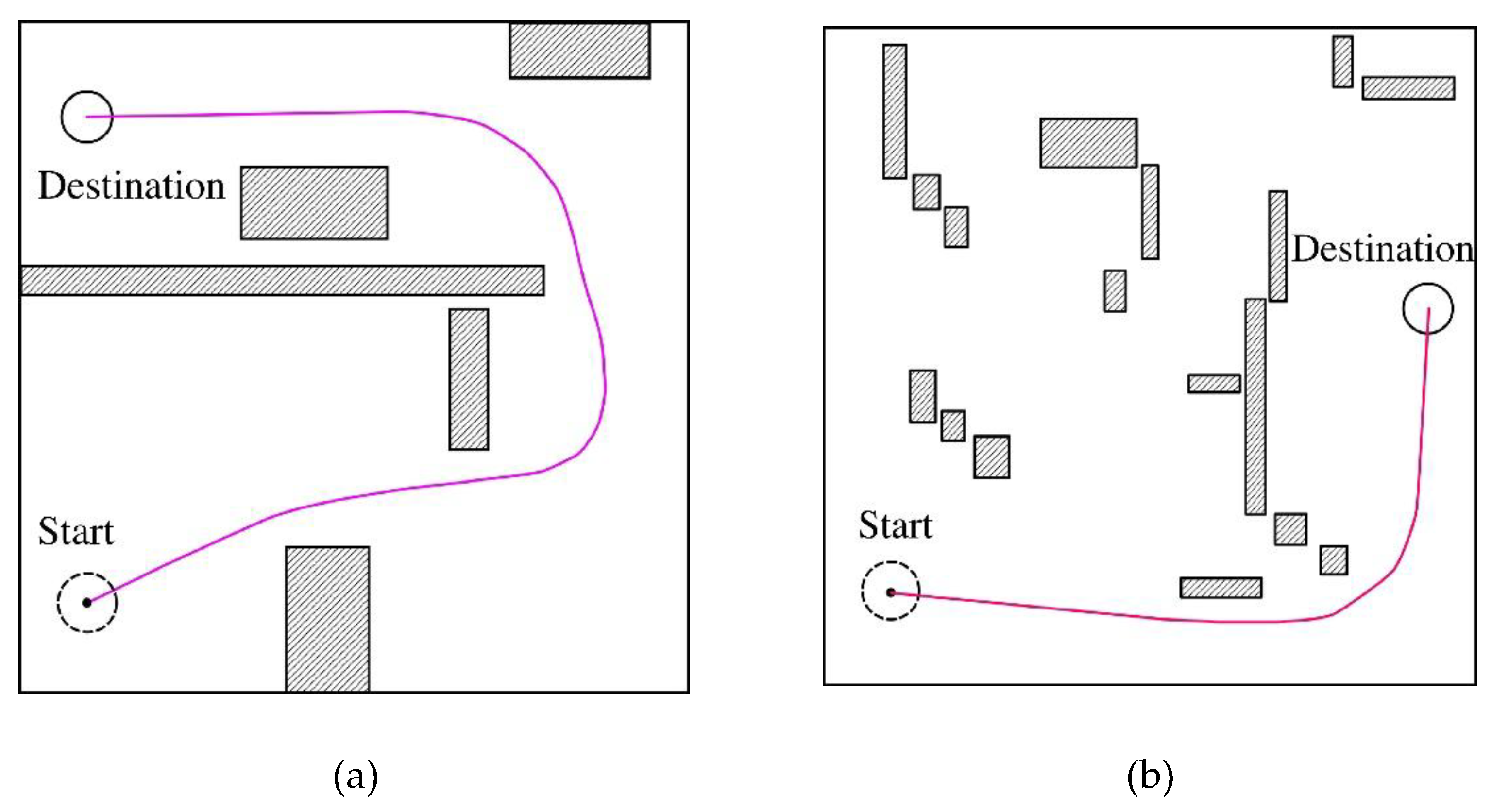
Figure 7.
(a) The UAV for autonomous flight in validating the path planning, (b) the on board STM32 microcontroller, and (c) the STM32 MCU. , and (d) mission planning visualization.
Figure 7.
(a) The UAV for autonomous flight in validating the path planning, (b) the on board STM32 microcontroller, and (c) the STM32 MCU. , and (d) mission planning visualization.
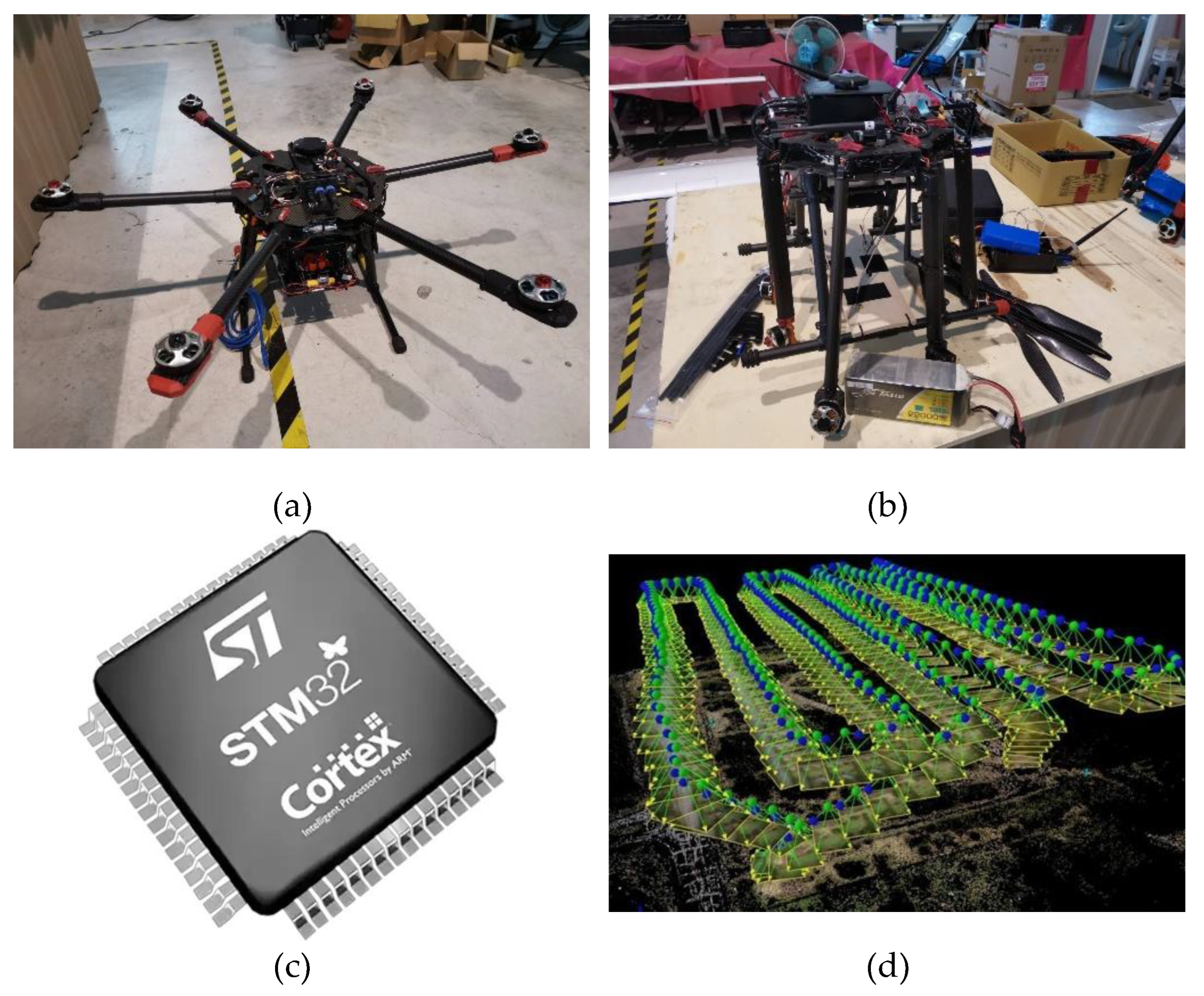
Figure 8.
The flight plan of an autonomous UAV.
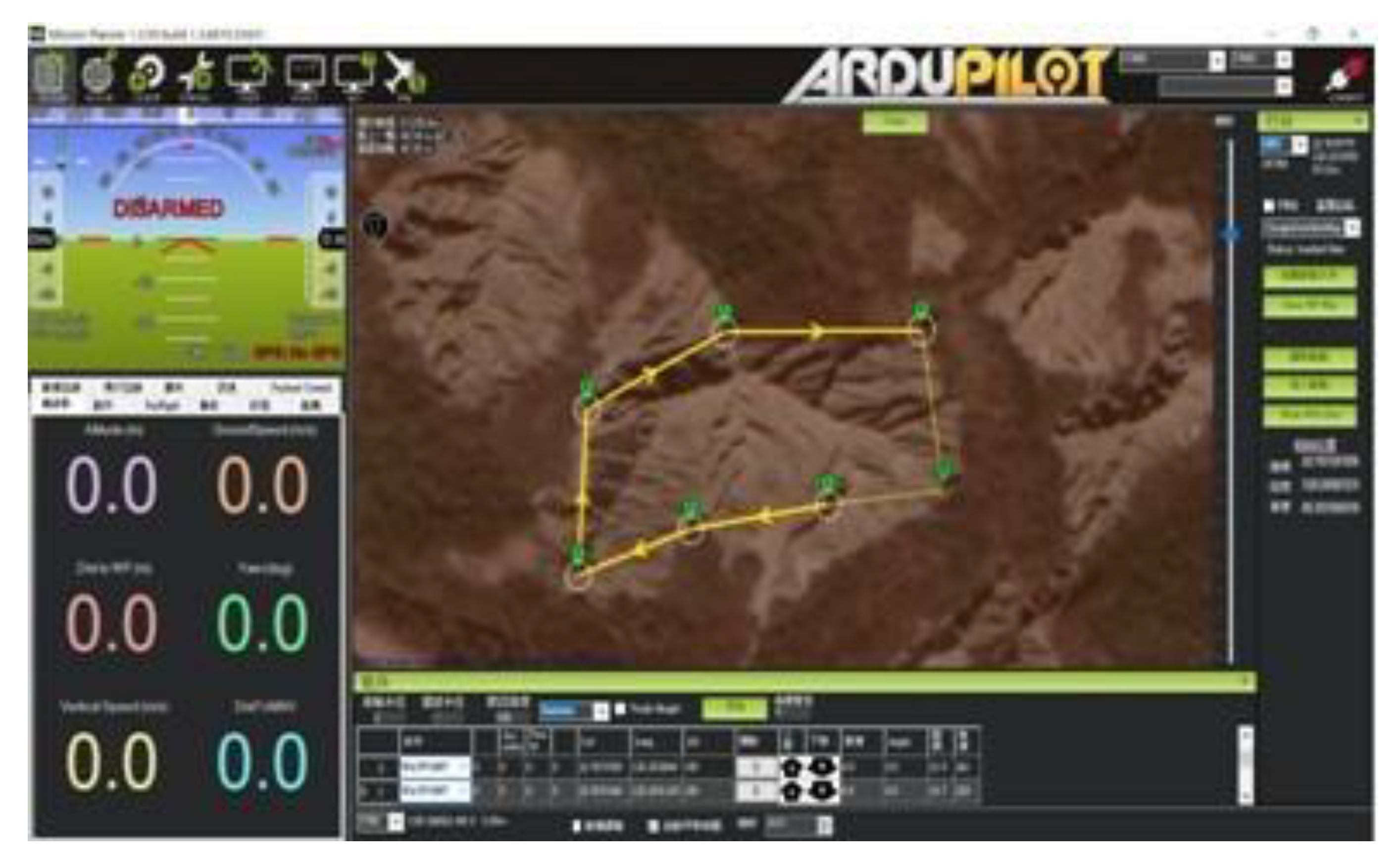
Figure 9.
Schematic diagram of flying at a fixed altitude while avoiding ground obstacles on the plane.
Figure 9.
Schematic diagram of flying at a fixed altitude while avoiding ground obstacles on the plane.
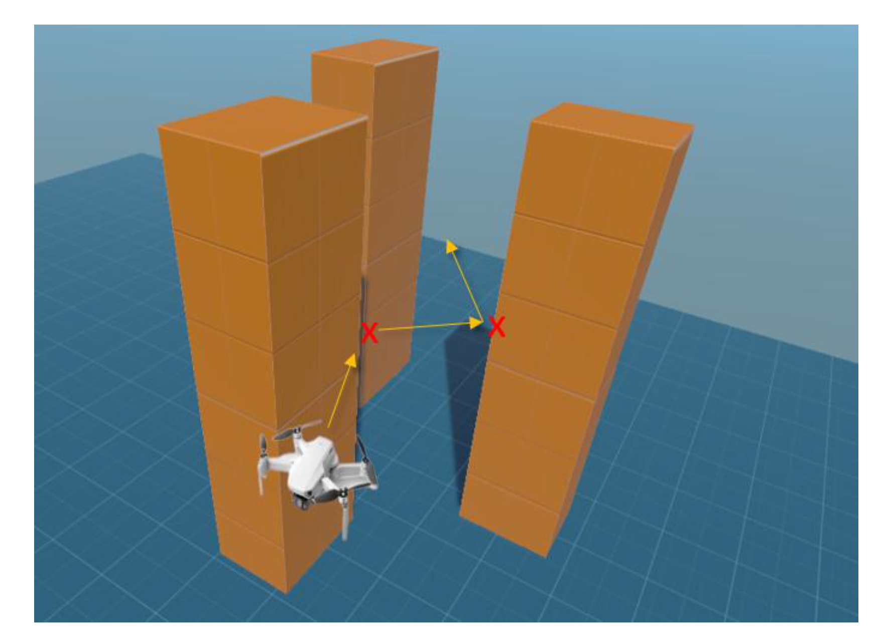
Figure 10.
The system architecture diagram.
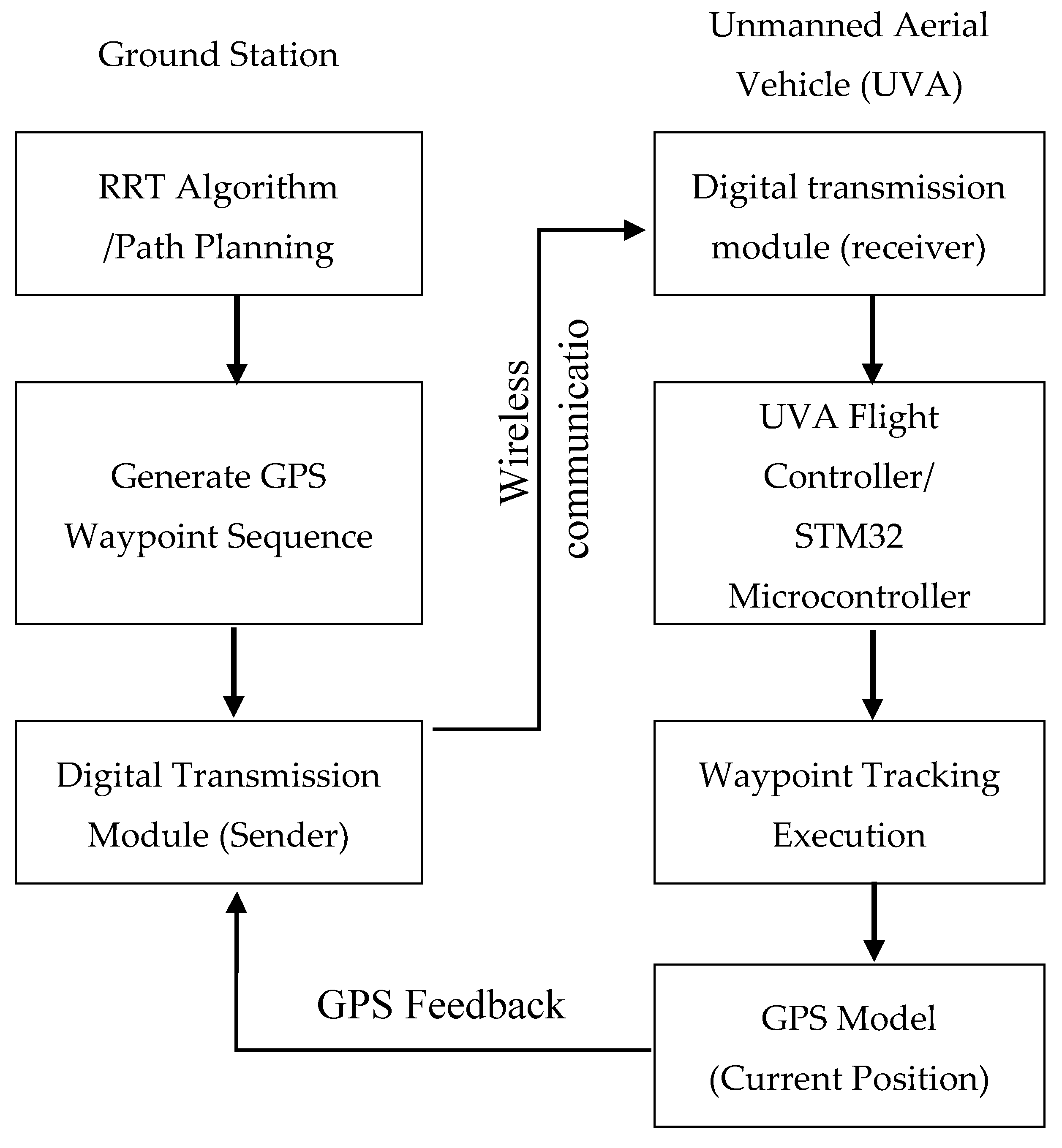
Figure 11.
Comparison between the planned path (blue line) generated by the onboard STM32 and the actual flight trajectory (red line) recorded from GPS data during the validation flight.
Figure 11.
Comparison between the planned path (blue line) generated by the onboard STM32 and the actual flight trajectory (red line) recorded from GPS data during the validation flight.
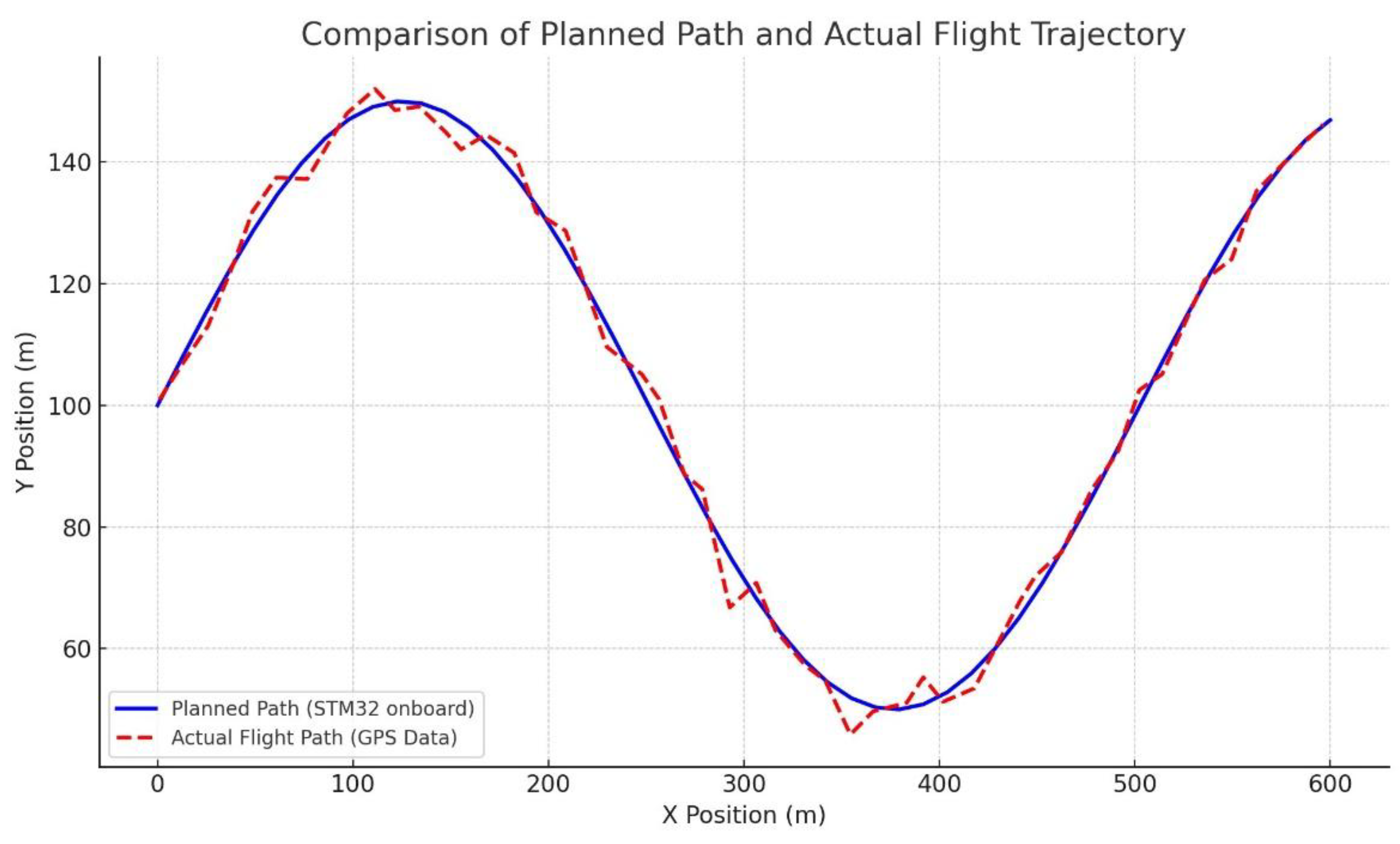
Table 1.
The success rate and average calculation time of different path planning.
| Number of path planning | Number of path planning | Number of path planning |
|---|---|---|
| 1 | 56 | 91 |
| 5 | 74 | 420 |
| 10 | 96 | 900 |
Table 2.
Quantitative results of the in-flight validation (Average of 5 runs).
| Metric | Planned Value | Actual Value | Error / Deviation |
|---|---|---|---|
| Path Length (m) | 583.0 | 591.2 | +1.4% |
| Flight Time (s) | 60.5 | 64.8 | +7.1% |
| Average Tracking Error (m) | N/A | 1.25 | ±0.3 m (Std. Dev.) |
Table 3.
Onboard computational performance on the STM32F103C8T6 (72 MHz).
| Algorithm Stage | Average Execution Time (ms) |
|---|---|
| RRT Tree Generation (10 runs) | 855 |
| Path Pruning | 62 |
| Bézier Curve Smoothing | 41 |
| Total Onboard Planning Time | 958 |
Table 4.
Comparative analysis with other path planning methods.
| Method | Typical Platform | Key Advantage | Key Limitation |
|---|---|---|---|
| RRT [24] | PythonRobotics | Asymptotically optimal path | Slow convergence, high computational cost |
| Dynamic RRT [25] | double integrator model with linear dynamics | Handles dynamic obstacles | Very computationally intensive |
| This Work | TM32 MCU | Low power (~99mW), low cost, validated onboard implementation | Sub-optimal path, static environment only |
Disclaimer/Publisher’s Note: The statements, opinions and data contained in all publications are solely those of the individual author(s) and contributor(s) and not of MDPI and/or the editor(s). MDPI and/or the editor(s) disclaim responsibility for any injury to people or property resulting from any ideas, methods, instructions or products referred to in the content. |
© 2025 by the authors. Licensee MDPI, Basel, Switzerland. This article is an open access article distributed under the terms and conditions of the Creative Commons Attribution (CC BY) license (http://creativecommons.org/licenses/by/4.0/).
Copyright: This open access article is published under a Creative Commons CC BY 4.0 license, which permit the free download, distribution, and reuse, provided that the author and preprint are cited in any reuse.


