
Submitted:
04 November 2025
Posted:
05 November 2025
You are already at the latest version
Abstract
3D printing enables high customization, and Fused Deposition Modelling (FDM) repre-sents a low-cost and accessible option increasingly adopted in medicine. In orthopedics, PLA patient-specific instruments (PSIs) enhance surgical precision and reproducibility, yet sterilization remains challenging for polymeric materials. Annealed HT-PLA im-proves thermal stability and mechanical performance, supporting its use for surgical cut-ting guides. This study investigates the dimensional behavior of pin holes, a key design feature in 3D printed cutting guides, with the aim of supporting proper dimensioning during the design phase. Response Surface Methodology (RSM) was applied to analyze how inner diameter and wall thickness change after annealing in HTPLA printed sam-ples. Results show that inner diameters decrease while wall thickness increases after thermal treatment. A quadratic model was developed, demonstrating that the final hole diameter depends on nominal diameter, wall thickness, and the square of the nominal diameter. These findings provide quantitative insight into the dimensional variations oc-curring during annealing and offer an initial reference for compensating shrinkage in the design of HTPLA cutting guides. These findings help establish preliminary design criteria to improve dimensional accuracy in 3D printed HTPLA PSIs, ensuring accurate hole siz-ing and stronger process robustness, ultimately supporting safer and more reliable surgi-cal application.
Keywords:
annealing
; high-temperature polylactic acid
; polylactic acid
; PLA
; cutting guides
; orthopedics
; fused deposition modelling
; 3D printing
; deformation
; thermal treatment
1. Introduction
3D printing, also known as additive manufacturing (AM), is a process based on the layer-by-layer addition of material to build objects directly from digital Computer Aided Design (CAD) models. Developed in the 1980s with Chuck Hull’s stereolithography (SLA) patent [1], 3D printing has rapidly evolved from a rapid-prototyping technology [2] to a key tool in aerospace, automotive, fashion, and medical sectors [3,4,5,6,7], enabling precise and complex shapes with high design freedom.
AM enables reduced overproduction, shorter supply chains, and lower material waste, especially for small, customized plastic components. Among AM technologies, Fused Deposition Modelling (FDM) is the most accessible and cost-effective [8], offering design flexibility, low equipment and material costs, and compatibility with numerous thermoplastics [9,10]. Over recent years, advances in filament development have improved manufacturability and surface quality. In particular, Polylactic Acid (PLA), a semicrystalline biopolymer, has gained widespread use due to its versatility, from biodegradable packaging and disposable goods to medical devices and personal care applications [11].
In healthcare, 3D printing has been used since the early 1990s, beginning with the reconstruction of cranial models from CT scans [12]. Now, it is widely adopted across multiple surgical fields, including oral and maxillofacial, cardiothoracic, plastic, neurosurgical and orthopedic surgery [13,14,15,16,17,18]. This technology enables the cost-effective production of customized prosthetics, implants, dental devices and anatomical models to support virtual surgical planning (VSP) [7,19]. More recently, it has also supported the creation of patient specific instruments (PSIs), such as surgical cutting guides and implants, further improving precision and personalization in clinical practice [20,21].
Particularly in orthopedics, 3D printed cutting guides, also referred to as drilling guides or surgical templates, assist surgeons by defining screw and wires trajectory, osteotomy orientation, and resection margins in bone tumor surgery [22,23]. They enhance precision, safety, and reproducibility, simplifying complex steps and supporting accurate execution of the VSP procedure. Particularly in pediatric orthopedics cases, they have also been associated with reductions in operating time, fluoroscopy exposure, bleeding, and complication rates, together with improved surgical accuracy and overall efficiency [24,25,26,27]. Additionally, these guides support training by offering structured intraoperative guidance and increasing confidence during complex procedures [28,29,30].
Efficient sterilization remains a key challenge for the clinical adoption of 3D printed parts, particularly those made of polymeric materials such as PLA. Steam sterilization is currently the preferred and most widely adopted method for 3D printed PSIs in hospitals, as alternative techniques are often less suitable [31,32]. Although elevated temperatures may cause deformation, steam sterilization is increasingly integrated into clinical 3D printing workflows.
Generally, PLA offers good printing quality and stiffness but has a low glass transition temperature, making it unable to maintain shape at moderate heat and unsuitable for thermal or steam sterilization [33]. To overcome these limitations, High-Temperature PLA (HTPLA) is a PLA containing crystallization agents that allow the polymer to stabilize at higher temperatures and improve mechanical performance. After thermal annealing, HTPLA gains strength, dimensional stability, and heat resistance, enabling compatibility with autoclave sterilization without significant deformation [34].
Among post-processing techniques for FDM parts, annealing is one of the most effective. By increasing crystallinity, it reduces internal stresses, improves interlayer adhesion, and enhances mechanical properties [35,36,37,38]. In PLA, higher crystallinity increases flexural strength, depending on the annealing temperature and heating/cooling cycles [39,40]. However, annealing can also alter dimensional tolerances, so shrinkage or expansion should be accounted for during design [41].
The design of 3D-printed cutting guides is highly case-specific and difficult to fully standardize, as each procedure presents unique anatomical and surgical requirements [42]. Nonetheless, certain features, such as fixation pins and screw trajectories and osteotomy orientation, are recurrent and critical to ensure accurate reproduction of the preoperative plan [43]. Since dimensional changes may occur after annealing and before sterilization, defining design strategies that anticipate these effects is essential to avoid instability or misalignment during surgery.
This study aims to begin establishing design guidelines by focusing on one key feature: the pin holes. It experimentally evaluates how the manufacturing process affects their final dimensions and develops a regression model to predict post-processing shrinkage, enabling designers to choose the correct nominal hole diameters during the design phase and ensure accurate pin fit, guide stability, and surgical precision.
2. Materials and Methods
This work focuses on improving the dimensional precision of the holes of the cutting guides used for pins. By varying the initial hole diameter and wall thickness, a predictive model is developed to compensate for the dimensional reduction occurring after the annealing phase of the process, to allow designers to set the correct dimensions in advance, ensuring that the final printed parts meet the exact requirements defined during the VSP phase.
2.1. Process Workflow
Our well-established PSI manufacturing process [44] (Figure 1) begins with a preparation phase, which includes a request from the surgeon and the acquisition of the patient’s CT scan. The scan is processed using Materialise Mimics (Leuven, Belgium) to segment the region of interest and generate a 3D virtual model of the target bone, which is then exported as an STL file.
Preoperative planning is subsequently performed in Blender (Amsterdam, The Netherlands), in close collaboration with the requesting surgeon. During this stage, key surgical parameters are defined, including correction angles, cutting planes, the dimensions and placement of fixation wires, the positioning of the cutting guide, and the surgical approach. Critical considerations also include nearby soft tissues and vital anatomical structures to be preserved. The entire surgical workflow is assessed, taking into account anatomical and clinical constraints as well as the instrumentation available in the operating room, including fixation plates when required. The available bone surface for accurate PSI placement is carefully evaluated.
Once all planning elements have been defined, the 3D model and surgical specifications are used to design the PSI in Creo Parametric (PTC, Boston, MA, USA). Design parameters are set based on the features and constraints identified during planning. Particular attention is paid to the diameter of the fixation wire holes, which represent the specific focus of this study.
The cutting guides designed are subsequently manufactured using FDM Bambu Lab X1 Carbon printer (Bambu Lab, Shenzhen, China), using HTPLA filament (Filamentum, Hulín, Czech Republic). The material choice and optimal printing parameters were established in previous studies [34,45]. Basic printing parameters and material properties are reported in Table 1 and Table 2.
Following printing, the components undergo a thermal annealing cycle, previously validated in earlier work, to stabilize their geometry and enhance mechanical properties and material strength. The material behaviour during this phase represents the critical phenomenon investigated in this study for the definition of design guidelines.
Finally, the finished instruments are sterilized and delivered directly to the operating room on the day of surgery.
2.2. Design of the Experiment
Cutting guides are extremely case-specific and therefore difficult to fully standardize, as previously discussed, due to the high level of customization required for each patient’s anatomy and the planned treatment. However, some key elements can be identified, namely: the main body of the PSI, the fixation pin holes, and the saw slot, which is the feature that guides the surgical saw during the osteotomy (Figure 2).
In this study, the pin-hole feature was isolated and evaluated separately, allowing a focused investigation of its dimensional behavior throughout the manufacturing process.
A set of samples with different dimensions was produced to collect data and define the relationship between planned and effective values. The specimen height was fixed at 5 mm to standardize the geometry and exclude it as a variable, ensuring that the analysis focused solely on inner diameter and hole thickness (Figure 3). After the 3D printing phase and subsequent annealing, the final dimensions were manually measured with a digital caliper. To derive an empirical formula capable of predicting the final inner diameter of the annealed specimens within the practical range of parameter values, response surface methodology (RSM) was applied. The purpose here is not to identify an optimization plateau, but rather to establish a usable relationship within the specific diameter range employed in practice.
Thirteen 3D printed samples were obtained from the combination of the selected parameters for a comprehensive study. As previously mentioned, the two factors under investigation were the inner diameter and thickness, for which a specific range of levels (“high” and “low”) was defined:
- The inner diameter was included as the main focus of the research, to investigate how it changes from the initial design to the final post-process condition. The values ranged from 1.6 mm to 5 mm, selected based on surgical practice, reflecting the minimum and maximum diameters commonly used in our experience in the operating room, and ensuring they could be reliably measured with a digital caliper at the end of the process, while accounting for a safety margin to accommodate shrinkage;
- Thickness was the second parameter considered, as the amount of material surrounding the inner diameter is expected to play a key role in the shrinkage results. The values were set between a minimum of 2 mm and a maximum of 6 mm.
For the optimization of design parameters in relation to the dimensional variation caused by annealing, a response surface approach was adopted. The Central Composite Design (CCD) is an extension of the factorial design that incorporates center points and axial points to estimate curvature. The position of the axial points depends on an alpha (α) value, which is determined by the number of points in the underlying factorial design. In this case, with a two-factor, two-level design (4 points), the corresponding α value is 1.414. Unlike a simple factorial design, which captures only linear effects and interactions, CCD enables modelling of both linear and quadratic terms, making it suitable for response surface analysis [46]. While CCD is typically applied to identify an optimum point, in this study it was used solely to develop a descriptive model, capturing the relationship between planned and effective dimensions within the practical range of values. The variable parameters and their level are described in Table 3.
2.3. Measurements
The experiment was conducted by designing the CAD model of each specimen according to the dimensions defined in the design of experiment. The specimens were subsequently 3D printed and annealed (Figure 4 and Figure 5 ), after which their final dimensions were manually measured with a digital caliper. These measurements were then compared with the initial CAD dimensions, from which also the theoretical volume was calculated (Table 4), to evaluate the dimensional changes induced by the process.
After the annealing process, the effective values of inner diameter, thickness, height (although not included in the design, it was monitored as a control), and volume were manually measured and calculated for each specimen. From these, the differences with respect to the designed values were computed (Δinner, Δthickness, Δheight, Δvolume, and Δvolume%) (Table 5).
The data were analysed based on RSM with a CCD, with inner diameter and thickness as independent factors. Quadratic regression models were fitted to evaluate linear, quadratic, and interaction effects on the measured responses. Model adequacy was assessed through Analysis of Variance (ANOVA), with a significance threshold set at p < 0.05. Non-significant terms were removed by stepwise regression where appropriate, to refine the predictive model. The resulting equations were used to generate response surface and contour plots, allowing a direct interpretation of the relationship between design parameters and dimensional variations after annealing.
3. Results
Preliminary inspection of the data clearly shows that the inner diameter consistently decreases (our data show a range from –0.4 to –0.9 mm), while the thickness systematically increases (data range from +0.1 to +0.4 mm). The height also shows a slight positive shift, even if it was maintained as a constant (from +0.2 to +0.3 mm). Overall, the volume displays only limited percentage variations, suggesting that the dimensional changes mainly result from a redistribution of material rather than an actual loss of volume, with the main dimensional effect being the reduction of the inner diameter, which represents the most critical feature for the correct fit of pins.
The response of interest was the final inner diameter, considering the varied values for the experiment (inner diameter and thickness) as independent factors. The model fit summary (Table 6) indicated that the quadratic model was the most suitable for describing the variation of our response. The linear and 2FI models were not adequate, despite showing high R² values, while the cubic model was aliased and therefore not considered. The quadratic model was statistically significant (p = 0.0129), with no significant lack-of-fit (p = 0.7698), and showed excellent agreement between adjusted R² (0.9984) and predicted R² (0.9973). Based on these results, the quadratic model was selected.
ANOVA results for the full quadratic model (Table 7) confirmed that the model was statistically significant (p < 0.0001). Among the individual terms, the factor inner diameter had the strongest effect on the final diameter (p < 0.0001), together with its quadratic term (p = 0.0047), indicating a non-linear relationship between nominal and final inner diameter. Conversely, the main effect of thickness was only marginally non-significant (p = 0.061), while the interaction (Inner Diameter*Thickness) and quadratic effect of thickness were clearly not significant
Based on these results, a model reduction was performed to retain only the significant terms. After model reduction, the ANOVA (Table 8) confirmed that the simplified model remained highly significant (p < 0.0001) with no lack of fit (p = 0.8646). The reduced model retained three terms: the main effects of inner diameter and thickness, as well as the quadratic effect of inner. Among these, inner diameter was by far the dominant factor (p < 0.0001), while thickness had a smaller but still significant effect (p = 0.0397). The quadratic term of inner diameter confirmed the presence of curvature in the relationship between nominal and final inner diameter. The interaction term and the quadratic term of thickness were excluded as they were not significant. The coefficients of determination confirmed the quality of the fit, with R² = 0.9989, Adjusted R² = 0.9986, and Predicted R² = 0.9982, all in close agreement.
Diagnostic plots confirmed the adequacy of the model (Figure 6): residuals were approximately normally distributed and the predicted vs. actual plot showed that the experimental data aligned closely with the bisector, indicating good predictive reliability.
In addition, contour and response surface plots (Figure 7) illustrate the effect of nominal inner diameter and thickness on the final inner diameter. The plots clearly illustrate that inner diameter is the dominant factor, with a non-linear curvature confirmed by the quadratic term, while thickness has a smaller but significant effect. These graphical representations allow a direct interpretation of how dimensional changes evolve across the design space and support the use of the regression model for predictive purposes.
The reduced quadratic model resulted in the following regression equation:
final diameter = -1.20343 + 1.29346 * inner diameter + 0.023928 * thickness – 0.032722 * inner diameter²
In this context, “inner diameter” refers to the nominal inner diameter defined in the CAD design, “thickness” to the nominal wall thickness of the hole, and “final diameter” to the effective diameter obtained after the annealing process. The model allows prediction of the final diameter for any combination of design parameters within the experimental range. Its strength lies in the possibility of inverting the regression equation to determine the nominal CAD diameter required to achieve a specific post-annealing size. This makes the model not only predictive but also directly applicable as a compensation rule during design, ensuring that the manufactured guides provide the correct fit for pins.
4. Discussion
There is limited literature addressing design parameters or process tuning specifically for 3D printed surgical instruments. As other authors have applied RSM to optimize properties of FDM-printed parts and obtain predictive models [47,48,49], we adopted the same methodological approach but focused on a critical geometrical feature (the diameter of pin holes) with the aim of developing a predictive equation directly applicable during the design phase.
Similarly to our work, Kwan et al. investigated the thickness and cutting slot height of in-house 3D printed jigs made of surgical-grade resin, assessing their effect on cutting accuracy and aiming to identify tangible design parameters to serve as guidelines [43]. Their study focused on a different feature, the saw slot, approached from a purely geometrical design perspective. While their goal was likewise to define design guidelines, they did not account for dimensional changes introduced during printing or sterilization, as we did. Their geometrical approach makes the results broadly applicable across different materials and technologies; however, since material-specific behaviours are not considered, their findings still require refinement and adaptation before being used.
Wijnbergen et al. investigated FDM with tough PLA for low-cost prosthetic sockets and evaluated different annealing methods. They reported that sand annealing produced the least deformation, whereas oven annealing of vertically placed rings resulted in the largest dimensional changes but also the greatest improvement in mechanical properties [50]. Their study also examined the deformation of test rings (conceptually similar to our specimens but 3D printed in the transverse direction and without dimensional variation) by measuring changes in inner diameter, thickness, and height under different annealing conditions. They also highlighted that the position of the part during annealing is an additional factor influencing deformation, an aspect not considered in our work but potentially relevant for future investigations alongside printing parameters and infill orientation. Furthermore, consistent with our findings, they observed that thickness was less sensitive to dimensional changes (p-value >0.05) compared to the inner diameter (p-value <0.05), although their experimental approach differed from ours.
Our study aligns with the recommendation of Popescu et al., who emphasized the importance of including adequate allowances in fit-critical areas during guide design [51]. By focusing on a specific feature of the cutting guide, we defined design parameters and developed an empirical regression model that enables compensation rules in CAD, ensuring that post-annealing dimensions match surgical requirements. As also noted by Popescu et al., these considerations strongly depend on the material and process used.
Limitations
This study has some limitations that should be acknowledged when interpreting the results. First, the regression model obtained through RSM is valid only within the experimental range of inner diameter and thickness investigated. The approach cannot be directly extrapolated to substantially different values, such as very large holes or very thin walls, which were not part of the tested domain. The predictive equation should therefore be considered a local model, accurate within the tested domain but requiring new calibration if the design space changes.
Second, the specimens were deliberately simplified to cylindrical rings with constant height to isolate the effect of the two studied parameters. This controlled geometry facilitates a clear interpretation of the results but does not fully reflect the complexity of real cutting guides, which may include multiple adjacent holes, irregular curvatures, and other local features that could affect deformation. In such cases, dimensional changes may also be influenced by interactions between neighbouring elements or by structural constraints not reproduced in our setup. Furthermore, the positioning of pin holes is not always guaranteed to be perpendicular to the build plate. When multiple holes are present and oriented differently from one another, some of them may end up being printed at different angles.
Third, although specimen height was fixed at 5 mm, slight variations were still observed after annealing. Since height was not investigated as a factor, its potential influence on deformation remains unexplored. It cannot be excluded that taller or thinner components may show different shrinkage or expansion behaviour, suggesting that height should be systematically varied in future studies to assess its role as an additional parameter.
In addition, the measurement of final dimensions was performed manually using a digital caliper. While care was taken to minimize operator bias, this method inherently carries a small degree of uncertainty compared to automated or scanning-based measurements. Employing 3D scanning techniques or optical metrology could improve accuracy and enable a more detailed mapping of deformation across the entire geometry.
Finally, the model is strongly material- and process-dependent. The predictive equation developed here applies specifically to HTPLA processed with the selected printer, printing parameters, and annealing protocol. Any change in material, print settings, or thermal treatment would alter the deformation behaviour, requiring renewed tuning of the model. This highlights both a limitation and an opportunity: the methodology can be replicated and adapted, but calibration is necessary whenever process or material conditions differ.
5. Conclusions
This study investigates how the annealing process affects pin holes in 3D printed cutting guides. The objective is to understand how dimensions defined during the design phase change after processing, so that nominal hole diameters can be adjusted to achieve the desired final size.
Further studies are needed to fully characterize the behavior of 3D printed PSIs and the other design features they include, such as multiple pin holes with different print orientations and guiding slots, which may deform differently depending on their geometry and positioning. In addition, future work should explore different printing parameters to validate and expand the applicability of these findings.
Nevertheless, this work represents an initial step toward establishing design guidelines for patient-specific cutting guides, supporting more predictable dimensional outcomes and improving process reliability, ultimately enhancing surgical precision, intraoperative stability, and overall workflow efficiency.
Author Contributions
Conceptualization, G.C.M. and G.A.; methodology, G.D., L.F.; software, G.A. and P.P.; validation,; formal analysis, A.D. and G.T.; investigation, G.C.M.; resources, G.T and G.R.; data curation, G.C.M. and P.P.; writing—original draft preparation, G.C.M.; writing—review and editing, A.D. and G.T.; visualization, G.A. and P.P.; supervision, G.D., L.F.; project administration, L.F., G.T. and G.R.; funding acquisition, G.D. All authors have read and agreed to the published version of the manuscript.
Funding
This research received no external funding.
Institutional Review Board Statement
Not applicable.
Informed Consent Statement
Not applicable.
Data Availability Statement
The original contributions presented in this study are included in the article. Further inquiries can be directed to the corresponding author.
Conflicts of Interest
The authors declare no conflicts of interest.
Abbreviations
The following abbreviations are used in this manuscript:
| AM | Additive Manufacturing |
| CAD | Computer-Aided-Design |
| SLA | Stereolithography |
| FDM | Fused Deposition Modelling |
| PLA | Polylactic Acid |
| HTPLA | High-Temperature Polylactic Acid |
| VSP | Virtual Surgical Planning |
| PSI | Patient-Specific-Instrument |
| RSM | Response Surface Methodology |
| CCD | Central Composite Design |
| ANOVA | Analysis of Variance |
References
- Hull, C. On Stereolithography. Virtual Phys Prototyp 2012, 7, 177. [Google Scholar] [CrossRef]
- Kruth, J.P.; Leu, M.C.; Nakagawa, T. Progress in Additive Manufacturing and Rapid Prototyping. CIRP Annals 1998, 47, 525–540. [Google Scholar] [CrossRef]
- Karkun, M.S.; Dharmalingam, S. 3D Printing Technology in Aerospace Industry – A Review. International Journal of Aviation, Aeronautics, and Aerospace 2022, 9, 4. [Google Scholar] [CrossRef]
- Blakey-Milner, B.; Gradl, P.; Snedden, G.; Brooks, M.; Pitot, J.; Lopez, E.; Leary, M.; Berto, F.; du Plessis, A. Metal Additive Manufacturing in Aerospace: A Review. Mater Des 2021, 209, 110008. [Google Scholar] [CrossRef]
- Mohanavel, V.; Ashraff Ali, K.S.; Ranganathan, K.; Allen Jeffrey, J.; Ravikumar, M.M.; Rajkumar, S. The Roles and Applications of Additive Manufacturing in the Aerospace and Automobile Sector. Mater Today Proc 2021, 47, 405–409. [Google Scholar] [CrossRef]
- Khajavi, S.H.; Mandolini, M. Additive Manufacturing in the Clothing Industry: Towards Sustainable New Business Models. Applied Sciences 2021, Vol. 11, Page 8994 2021, 11, 8994. [Google Scholar] [CrossRef]
- Javaid, Mohd. ; Haleem, A. Additive Manufacturing Applications in Medical Cases: A Literature Based Review. Alexandria Journal of Medicine 2018, 54, 411–422. [Google Scholar] [CrossRef]
- Thomas, D.S.; Gilbert, S.W. Costs and Cost Effectiveness of Additive Manufacturing. 2014. [CrossRef]
- Cano-Vicent, A.; Tambuwala, M.M.; Hassan, S.S.; Barh, D.; Aljabali, A.A.A.; Birkett, M.; Arjunan, A.; Serrano-Aroca, Á. Fused Deposition Modelling: Current Status, Methodology, Applications and Future Prospects. Addit Manuf 2021, 47, 102378. [Google Scholar] [CrossRef]
- Shahrubudin, N.; Lee, T.C.; Ramlan, R. An Overview on 3D Printing Technology: Technological, Materials, and Applications. Procedia Manuf 2019, 35, 1286–1296. [Google Scholar] [CrossRef]
- Doshi, M.; Mahale, A.; Singh, S.K.; Deshmukh, S. Printing Parameters and Materials Affecting Mechanical Properties of FDM-3D Printed Parts: Perspective and Prospects. Mater Today Proc 2022, 50, 2269–2275. [Google Scholar] [CrossRef]
- Mankovich, N.J.; Cheeseman, A.M.; Stoker, N.G. The Display of Three-Dimensional Anatomy with Stereolithographic Models. J Digit Imaging 1990, 3, 200–203. [Google Scholar] [CrossRef]
- Choi, J.W.; Kim, N. Clinical Application of Three-Dimensional Printing Technology in Craniofacial Plastic Surgery. Arch Plast Surg 2015, 42, 267. [Google Scholar] [CrossRef] [PubMed]
- Giannopoulos, A.A.; Steigner, M.L.; George, E.; Barile, M.; Hunsaker, A.R.; Rybicki, F.J.; Mitsouras, D. Cardiothoracic Applications of 3-Dimensional Printing. J Thorac Imaging 2016, 31, 253–272. [Google Scholar] [CrossRef]
- Chae, M.P.; Rozen, W.M.; McMenamin, P.G.; Findlay, M.W.; Spychal, R.T.; Hunter-Smith, D.J. Emerging Applications of Bedside 3D Printing in Plastic Surgery. Front Surg 2015, 2, 25. [Google Scholar] [CrossRef]
- Randazzo, M.; Pisapia, J.; Singh, N.; Thawani, J. 3D Printing in Neurosurgery: A Systematic Review. Surg Neurol Int 2016, 7, S801. [Google Scholar] [CrossRef]
- Wong, T.M.; Jin, J.; Lau, T.W.; Fang, C.; Yan, C.H.; Yeung, K.; To, M.; Leung, F. The Use of Three-Dimensional Printing Technology in Orthopaedic Surgery. J Orthop Surg (Hong Kong) 2017, 25. [CrossRef]
- Auricchio, F.; Marconi, S. 3D Printing: Clinical Applications in Orthopaedics and Traumatology. EFORT Open Rev 2017, 1, 121–127. [Google Scholar] [CrossRef] [PubMed]
- Jariwala, S.H.; Lewis, G.S.; Bushman, Z.J.; Adair, J.H.; Donahue, H.J. 3D Printing of Personalized Artificial Bone Scaffolds. 3D Print Addit Manuf 2015, 2, 56–64. [Google Scholar] [CrossRef]
- Hao, Y.; Luo, D.; Wu, J.; Wang, L.; Xie, K.; Yan, M.; Dai, K. A Novel Revision System for Complex Pelvic Defects Utilizing 3D-Printed Custom Prosthesis. J Orthop Translat 2021, 31, 102–109. [Google Scholar] [CrossRef] [PubMed]
- Aimar, A.; Palermo, A.; Innocenti, B. The Role of 3D Printing in Medical Applications: A State of the Art. J Healthc Eng 2019, 2019, 5340616. [Google Scholar] [CrossRef]
- Ritacco, L.E.; Milano, F.E.; Farfalli, G.L.; Ayerza, M.A.; Muscolo, D.L.; Aponte-Tinao, L.A. Accuracy of 3-D Planning and Navigation in Bone Tumor Resection. Orthopedics 2013, 36. [Google Scholar] [CrossRef]
- Kamat, A.; Chinder, P.; Gopurathingal, A.; Hindiskere, S. 3D Printing in Orthopedic Oncology — Workflow and Outcomes of 59 Cases. Indian J Surg Oncol 2025, 1–13. [Google Scholar] [CrossRef]
- Raza, M.; Murphy, D.; Gelfer, Y. The Effect of Three-Dimensional (3D) Printing on Quantitative and Qualitative Outcomes in Paediatric Orthopaedic Osteotomies: A Systematic Review. EFORT Open Rev 2021, 6, 130. [Google Scholar] [CrossRef] [PubMed]
- Yammine, K.; Karbala, J.; Maalouf, A.; Daher, J.; Assi, C. Clinical Outcomes of the Use of 3D Printing Models in Fracture Management: A Meta-Analysis of Randomized Studies. Eur J Trauma Emerg Surg 2022, 48, 3479–3491. [Google Scholar] [CrossRef]
- Papotto, G.; Testa, G.; Mobilia, G.; Perez, S.; Dimartino, S.; Giardina, S.M.C.; Sessa, G.; Pavone, V. Use of 3D Printing and Pre-Contouring Plate in the Surgical Planning of Acetabular Fractures: A Systematic Review. Orthop Traumatol Surg Res 2022, 108. [Google Scholar] [CrossRef]
- Aguado-Maestro, I.; Simón-Pérez, C.; García-Alonso, M.; Ailagas-De Las Heras, J.J.; Paredes-Herrero, E. Clinical Applications of “In-Hospital” 3D Printing in Hip Surgery: A Systematic Narrative Review. Journal of Clinical Medicine 2024, Vol. 13, Page 599 2024, 13, 599. [Google Scholar] [CrossRef]
- Meng, M.; Wang, J.; Sun, T.; Zhang, W.; Zhang, J.; Shu, L.; Li, Z. Clinical Applications and Prospects of 3D Printing Guide Templates in Orthopaedics. J Orthop Translat 2022, 34, 22. [Google Scholar] [CrossRef]
- Yilmaz, A.; Badria, A.F.; Huri, P.Y.; Huri, G. 3D-Printed Surgical Guides. Ann Jt 2019, 4. [Google Scholar] [CrossRef]
- George, M.; Aroom, K.R.; Hawes, H.G.; Gill, B.S.; Love, J. 3D Printed Surgical Instruments: The Design and Fabrication Process. World J Surg 2017, 41, 314–319. [Google Scholar] [CrossRef] [PubMed]
- Tipnis, N.P.; Burgess, D.J. Sterilization of Implantable Polymer-Based Medical Devices: A Review. Int J Pharm 2018, 544, 455–460. [Google Scholar] [CrossRef]
- Pérez Davila, S.; González Rodríguez, L.; Chiussi, S.; Serra, J.; González, P. How to Sterilize Polylactic Acid Based Medical Devices? Polymers 2021, Vol. 13, Page 2115 2021, 13, 2115. [Google Scholar] [CrossRef] [PubMed]
- Hamad, K.; Kaseem, M.; Yang, H.W.; Deri, F.; Ko, Y.G. Properties and Medical Applications of Polylactic Acid: A Review. Express Polym Lett 2015, 9, 435–455. [Google Scholar] [CrossRef]
- Frizziero, L.; Santi, G.M.; Leon-Cardenas, C.; Ferretti, P.; Sali, M.; Gianese, F.; Crescentini, N.; Donnici, G.; Liverani, A.; Trisolino, G.; et al. Heat Sterilization Effects on Polymeric, FDM-Optimized Orthopedic Cutting Guide for Surgical Procedures. J Funct Biomater 2021, 12. [Google Scholar] [CrossRef] [PubMed]
- Ravoori, D.; Salvi, S.; Prajapati, H.; Qasaimeh, M.; Adnan, A.; Jain, A. Void Reduction in Fused Filament Fabrication (FFF) through in Situ Nozzle-Integrated Compression Rolling of Deposited Filaments. Virtual Phys Prototyp 2021, 16, 146–159. [Google Scholar] [CrossRef]
- Kim, H.-C.; Kim, D.-Y.; Lee, J.-E.; Park, K. Improvement of Mechanical Properties and Surface Finish of 3d-Printed Polylactic Acid Parts by Constrained Remelting. Adv Mater Lett 2017, 8, 1199–1203. [Google Scholar] [CrossRef]
- Lee, S.K.; Kim, Y.R.; Kim, S.H.; Kim, J.H. Investigation of the Internal Stress Relaxation in FDM 3D Printing : Annealing Conditions. Journal of the Korean Society of Manufacturing Process Engineers 2018, 17, 130–136. [Google Scholar] [CrossRef]
- Liao, Y.; Liu, C.; Coppola, B.; Barra, G.; Di Maio, L.; Incarnato, L.; Lafdi, K. Effect of Porosity and Crystallinity on 3D Printed PLA Properties. Polymers 2019, Vol. 11, Page 1487 2019, 11, 1487. [Google Scholar] [CrossRef]
- Wach, R.A.; Wolszczak, P.; Adamus-Wlodarczyk, A. Enhancement of Mechanical Properties of FDM-PLA Parts via Thermal Annealing. Macromol Mater Eng 2018, 303, 1800169. [Google Scholar] [CrossRef]
- Singh, S.; Singh, M.; Prakash, C.; Gupta, M.K.; Mia, M.; Singh, R. Optimization and Reliability Analysis to Improve Surface Quality and Mechanical Characteristics of Heat-Treated Fused Filament Fabricated Parts. International Journal of Advanced Manufacturing Technology 2019, 102, 1521–1536. [Google Scholar] [CrossRef]
- Butt, J.; Bhaskar, R. Investigating the Effects of Annealing on the Mechanical Properties of FFF-Printed Thermoplastics. Journal of Manufacturing and Materials Processing 2020, Vol. 4, Page 38 2020, 4, 38. [Google Scholar] [CrossRef]
- Caiti, G.; Dobbe, J.G.G.; Strijkers, G.J.; Strackee, S.D.; Streekstra, G.J. Positioning Error of Custom 3D-Printed Surgical Guides for the Radius: Influence of Fitting Location and Guide Design. International Journal of Computer Assisted Radiology and Surgery 2017 13:4 2017, 13, 507–518. [Google Scholar] [CrossRef]
- Kwan, Y.H.; Owyang, D.; Ho, S.W.L.; Yam, M.G.J. 3D-Printed Patient Specific Surgical Guides: Balancing Accuracy with Practicality. J Clin Orthop Trauma 2023, 46, 102293. [Google Scholar] [CrossRef]
- Frizziero, L.; Pagliari, C.; Donnici, G.; Liverani, A.; Santi, G.M.; Papaleo, P.; Napolitano, F.; Leon-Cardenas, C.; Trisolino, G.; Zarantonello, P.; et al. Effectiveness Assessment of CAD Simulation in Complex Orthopedic Surgery Practices. Symmetry (Basel) 2021, 13. [Google Scholar] [CrossRef]
- Ferretti, P.; Leon-Cardenas, C.; Santi, G.M.; Sali, M.; Ciotti, E.; Frizziero, L.; Donnici, G.; Liverani, A. Relationship between FDM 3D Printing Parameters Study: Parameter Optimization for Lower Defects. Polymers (Basel) 2021, 13. [Google Scholar] [CrossRef]
- Montgomery, D.C. Design and Analysis of Experiments. 2013.
- Radhwan, H.; Shayfull, Z.; Farizuan, M.R.; Effendi, M.S.M.; Irfan, A.R. Optimization Parameter Effects on the Quality Surface Finish of the Three-Dimensional Printing (3D-Printing) Fused Deposition Modeling (FDM) Using RSM. AIP Conf Proc 2019, 2129. [Google Scholar] [CrossRef]
- Firtikiadis, L.; Tzotzis, A.; Kyratsis, P.; Efkolidis, N. Response Surface Methodology (RSM)-Based Evaluation of the 3D-Printed Recycled-PETG Tensile Strength. Applied Mechanics 2024, Vol. 5, Pages 924-937 2024, 5, 924–937. [Google Scholar] [CrossRef]
- Donnici, G.; Freddi, M.; Liverani, A. RSM Applied to Lattice Patterns for Stiffness Optimization. Rapid Prototyp J 2024, 30, 344–355. [Google Scholar] [CrossRef]
- Wijnbergen, D.C.; van der Stelt, M.; Verhamme, L.M. The Effect of Annealing on Deformation and Mechanical Strength of Tough PLA and Its Application in 3D Printed Prosthetic Sockets. Rapid Prototyp J 2021, 27, 81–89. [Google Scholar] [CrossRef]
- Popescu, D.; Iacob, M.C.; Marinescu, R. Dimensional Accuracy of 3D-Printed Surgical Cutting Guides after Hospital Sterilization: A Comparative Evaluation of Ten MEX Materials. 3D Print Med 2025, 11, 1–18. [Google Scholar] [CrossRef]
Figure 1.
Overview of the workflow simplified in the main steps from patient selection to 3D printing and surgery.
Figure 1.
Overview of the workflow simplified in the main steps from patient selection to 3D printing and surgery.

Figure 2.
Illustrative example of a cutting guide showing its main structural features.
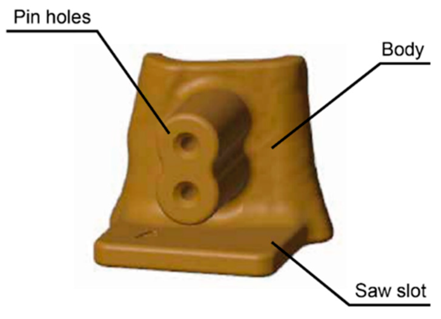
Figure 3.
3D representation of the specimen with a fixed height of 5 mm and variable inner diameter and thickness.
Figure 3.
3D representation of the specimen with a fixed height of 5 mm and variable inner diameter and thickness.
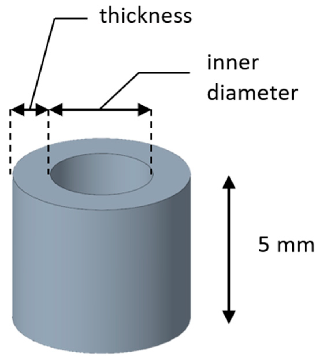
Figure 4.
The 13 specimens randomly arranged on the build plate according to the randomized order.
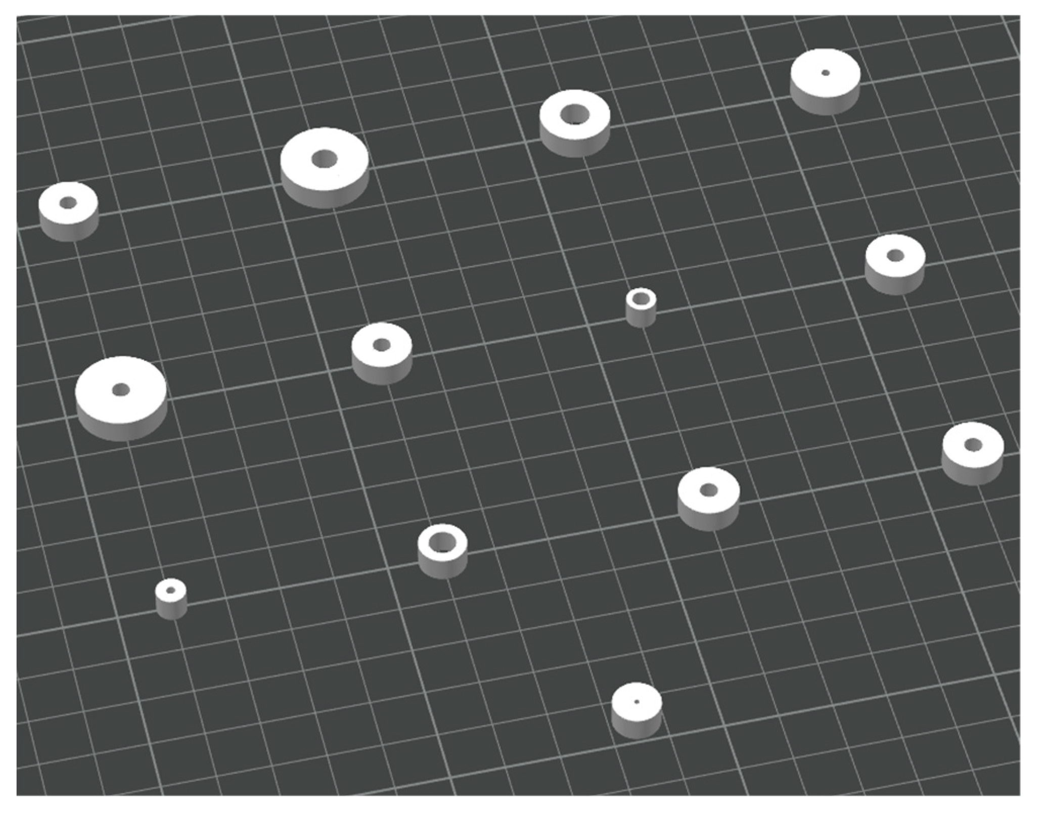
Figure 5.
The 13 specimens after annealing, ready for measurement.
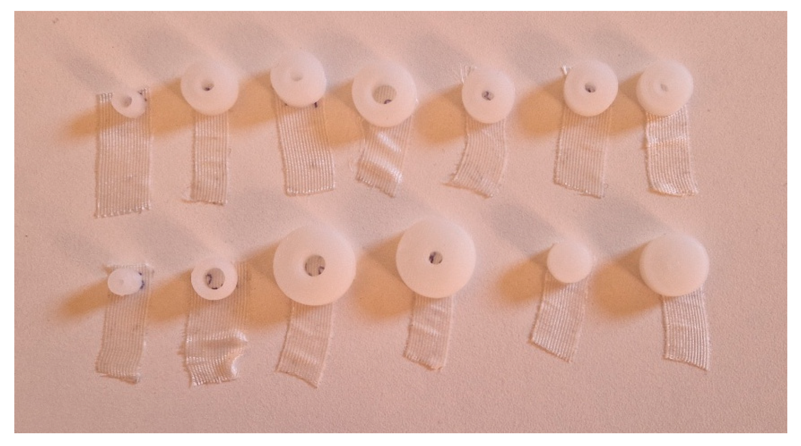
Figure 6.
(a) Normal probability plot of residuals confirming the normal distribution of the data; (b) Predicted vs. actual plot demonstrating good predictive accuracy of the model.
Figure 6.
(a) Normal probability plot of residuals confirming the normal distribution of the data; (b) Predicted vs. actual plot demonstrating good predictive accuracy of the model.
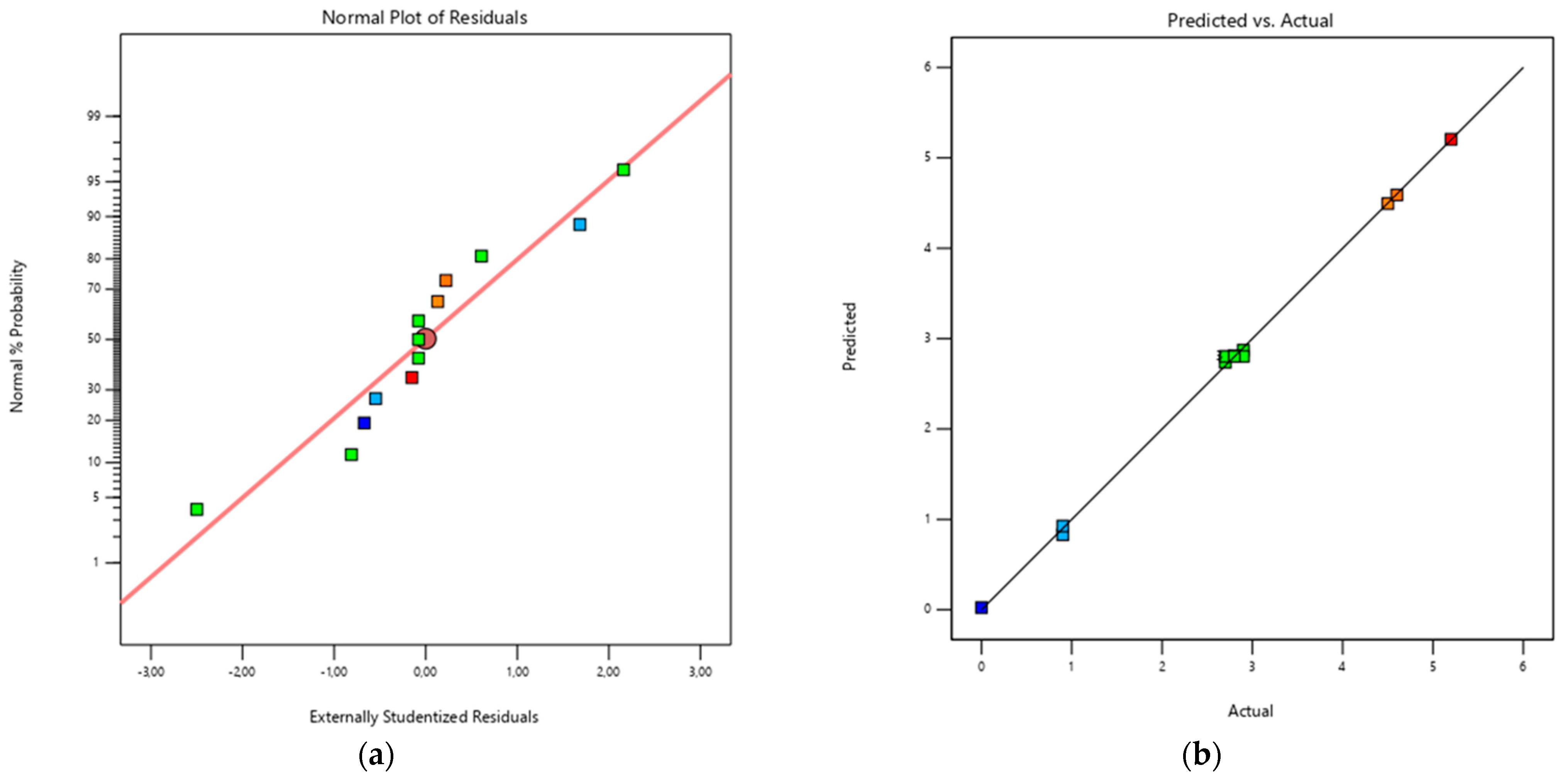
Figure 7.
(a) Contour plot and response surface plot (b) illustrating the effect of the factors of the model on the final diameter.
Figure 7.
(a) Contour plot and response surface plot (b) illustrating the effect of the factors of the model on the final diameter.
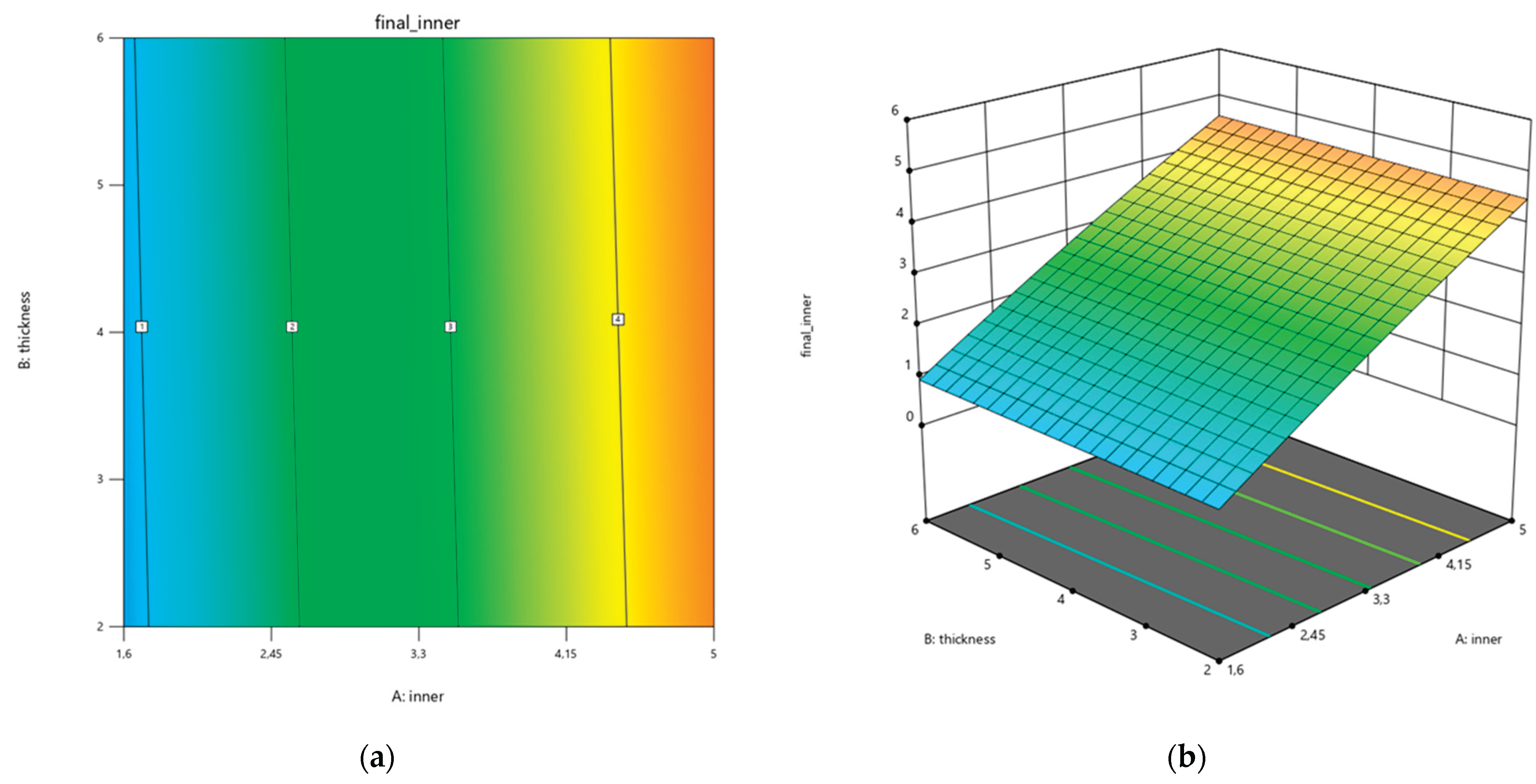

Table 1.
Main Properties of HTPLA (PLA Crystal Clear, Fillamentum Manufacturing Czech).
| Thermal properties | Glass transition temperature | 55-60 °C |
| Melting point | 150-230 °C | |
| Decomposition temperature | >230 °C | |
| Printing properties | Print temperature | 210-230 °C |
| Hot pad | 50-60 °C | |
| Physical Properties | Material density | 1.24 g/cm3 |
| Mechanical properties | Tensile strength | 50 MPa |
Table 2.
Optimized printing parameters defined for HTPLA cutting guide 3D printing.
| Layer (mm) | Line Width (mm) | Infill (%) | Infill pattern |
Infill/Wall Overlap (%) |
Wall loops | T Nozzle (°C) | T Bed (°C) | |
| HTPLA | 0.2 | 0.4 | 100 | Monotonic | 30 | 3 | 220 | 60 |
Table 3.
High and low levels of the variable parameters.
| Levels | |||
| Low (-) | High (+) | ||
| Inner diameter (mm) | 1.6 | 5 | |
| Thickness (mm) | 2 | 6 | |
Table 4.
Central Composite Design of the experiments, including randomized run order, point type and corresponding values (in mm). Please note that the height is maintained constant at 5 mm in the experiment.
Table 4.
Central Composite Design of the experiments, including randomized run order, point type and corresponding values (in mm). Please note that the height is maintained constant at 5 mm in the experiment.
| Standard Order | Run Order | Point Type | Variables | Height | Volume | ||
| Inner Diameter | Thickness | ||||||
| 1 | 11 | Factorial | 1.6 | 2 | 5.0 | 163.3 | |
| 2 | 8 | Factorial | 5 | 2 | 5.0 | 376.8 | |
| 3 | 3 | Factorial | 1.6 | 6 | 5.0 | 866.6 | |
| 4 | 4 | Factorial | 5 | 6 | 5.0 | 1507.2 | |
| 5 | 1 | Axial | 0.9 | 4 | 5.0 | 363.7 | |
| 6 | 6 | Axial | 5.7 | 4 | 5.0 | 967.6 | |
| 7 | 9 | Axial | 3.3 | 1.2 | 5.0 | 142.9 | |
| 8 | 2 | Axial | 3.3 | 6.8 | 5.0 | 1439.6 | |
| 9 | 7 | Center | 3.3 | 4 | 5.0 | 665.7 | |
| 10 | 12 | Center | 3.3 | 4 | 5.0 | 665.7 | |
| 11 | 13 | Center | 3.3 | 4 | 5.0 | 665.7 | |
| 12 | 5 | Center | 3.3 | 4 | 5.0 | 665.7 | |
| 13 | 10 | Center | 3.3 | 4 | 5.0 | 665.7 | |
Table 5.
Final measurement and values for each specimen.
| Standard Order |
Final Inner |
Final Thickness |
Final Height |
Final Volume |
Δinner | Δthickness | Δheight | Variables | ||
| Inner Diameter | Thickness | |||||||||
| 1 | 0.90 | 2.40 | 5.20 | 164.59 | -0.70 | 0.40 | 0.20 | 1.31 | 0.01 | |
| 2 | 4.50 | 2.10 | 5.20 | 380.61 | -0.50 | 0.10 | 0.20 | 3.81 | 0.01 | |
| 3 | 0.90 | 6.40 | 5.30 | 873.37 | -0.70 | 0.40 | 0.30 | 6.73 | 0.01 | |
| 4 | 4.60 | 6.00 | 5.30 | 1517.75 | -0.40 | 0.00 | 0.30 | 10.55 | 0.01 | |
| 5 | 0.00 | 4.30 | 5.30 | 307.71 | -0.90 | 0.30 | 0.30 | -56.01 | -0.15 | |
| 6 | 5.20 | 4.20 | 5.20 | 1001.23 | -0.50 | 0.20 | 0.20 | 33.59 | 0.03 | |
| 7 | 2.70 | 1.50 | 5.10 | 165.74 | -0.60 | 0.33 | 0.10 | 22.80 | 0.16 | |
| 8 | 2.90 | 6.90 | 5.30 | 1458.34 | -0.40 | 0.07 | 0.30 | 18.73 | 0.01 | |
| 9 | 2.80 | 4.20 | 5.30 | 684.98 | -0.50 | 0.20 | 0.30 | 19.30 | 0.03 | |
| 10 | 2.80 | 4.10 | 5.30 | 661.85 | -0.50 | 0.10 | 0.30 | -3.83 | -0.01 | |
| 11 | 2.70 | 4.20 | 5.20 | 658.34 | -0.60 | 0.20 | 0.20 | -7.34 | -0.01 | |
| 12 | 2.90 | 4.30 | 5.20 | 709.13 | -0.40 | 0.30 | 0.20 | 43.45 | 0.07 | |
| 13 | 2.80 | 4.20 | 5.30 | 684.98 | -0.50 | 0.20 | 0.30 | 19.30 | 0.03 | |
Table 6.
Fit summary for the choice of the model.
| Model |
Sequential p-value |
Lack of Fit p-value |
Adjusted R² | Predicted R² | |
| Linear | < 0.0001 | 0.2086 | 0.9959 | 0.9938 | Not adequate |
| 2FI | 0.6278 | 0.1723 | 0.9956 | 0.9935 | Not adequate |
| Quadratic | 0.0129 | 0.7698 | 0.9984 | 0.9973 | Suggested |
| Cubic | 0.6161 | 0.6433 | 0.9981 | 0.9959 | Aliased |
Table 7.
ANOVA analysis for the full quadratic model.
| Sum of Squares | df | Mean Square | F-value | p-value | |
| Model | 26.93 | 5 | 5.39 | 1461.57 | < 0.0001* |
| Inner Diameter | 26.84 | 1 | 26.84 | 7284.95 | < 0.0001* |
| Thickness | 0.0183 | 1 | 0.0183 | 4.97 | 0.0610 |
| Inner Diameter*Thickness | 0.0025 | 1 | 0.0025 | 0.6785 | 0.4373 |
| Inner Diameter² | 0.0611 | 1 | 0.0611 | 16.59 | 0.0047* |
| Thickness² | 0.0003 | 1 | 0.0003 | 0.0737 | 0.7938 |
| Residual | 0.0258 | 7 | 0.0037 | ||
| Lack of Fit | 0.0058 | 3 | 0.0019 | 0.3861 | 0.7698 |
| Pure Error | 0.0200 | 4 | 0.0050 | ||
| Cor Total | 26.95 | 12 |
* Values in bold with an asterisk highlight the factors that are statistically significant (p < 0.05).
Table 8.
ANOVA analysis for model reduction.
| Sum of Squares | df | Mean Square | F-value | p-Value | |||
| Model | 26.92 | 3 | 8.97 | 2827.73 | < 0.0001* | ||
| Inner Diameter | 26.84 | 1 | 26.84 | 8457.48 | < 0.0001* | ||
| Thickness | 0.0183 | 1 | 0.0183 | 5.77 | 0.0397* | ||
| Inner Diameter² | 0.0633 | 1 | 0.0633 | 19.94 | 0.0016* | ||
| Residual | 0.0286 | 9 | 0.0032 | ||||
| Lack of Fit | 0.0086 | 5 | 0.0017 | 0.3426 | 0.8646 | ||
| Pure Error | 0.0200 | 4 | 0.0050 | ||||
| Cor Total | 26.95 | 12 | |||||
| R² = 0.9989 | Adjusted R² = 0.9986 | Predicted R² = 0.9982 | |||||
* Values in bold with an asterisk highlight the factors that are statistically significant (p < 0.05).
Disclaimer/Publisher’s Note: The statements, opinions and data contained in all publications are solely those of the individual author(s) and contributor(s) and not of MDPI and/or the editor(s). MDPI and/or the editor(s) disclaim responsibility for any injury to people or property resulting from any ideas, methods, instructions or products referred to in the content. |
© 2025 by the authors. Licensee MDPI, Basel, Switzerland. This article is an open access article distributed under the terms and conditions of the Creative Commons Attribution (CC BY) license (http://creativecommons.org/licenses/by/4.0/).
Copyright: This open access article is published under a Creative Commons CC BY 4.0 license, which permit the free download, distribution, and reuse, provided that the author and preprint are cited in any reuse.


