
Submitted:
04 November 2025
Posted:
05 November 2025
You are already at the latest version
Abstract
This research addresses to find a suitable design solution in order to model the behavior of human center of mass and implement this in an exoskeleton structure especially designed for children walking assistance and rehabilitation. One of the most general problems on exoskeleton designs is represented by the ground – foot contact on exoskeleton behavior under kinematic and dynamic conditions. Thus, for solving this, the main research objective is to develop a mechanical system which will substitute the human center of mass CoM behavior on an exoskeleton especially designed for children with Duchenne Muscular Dystrophy. The research core focuses on modelling the human CoM behavior under kinematic circumstances and transferring this through a mechanical system conceptual design. The obtained results will validate the proposed mechanical system through a comparative analysis between numerical processing, virtual prototyping and experimental specific methods and procedures.
Keywords:
exoskelton
; human center of mass
; kinematics
; Duchenne muscular dystrophy
; translational joint
; damper
1. Introduction
The center of mass (CoM) of the human body has an essential role in the biomechanics of human gait, since its position and displacement during walking influence energy expenditure, stability, and movement efficiency. Thus, the CoM follows a sinusoidal trajectory in the vertical and transversal planes, as described in [1], and excessively large vertical oscillations lead to increased energy consumption due to the body’s upward and downward movement with each step.
To ensure the stability of the human body while walking, the CoM must remain above the base of support. The base of support is given by the foot of the lower limb in contact with the ground. When the CoM shifts too far away, the body needs adjustments to avoid losing balance (through arm swing of the upper limbs, movement of the thoracic cage, or step modification).
CoM excessive transversal oscillations can reduce stability by increasing the risk of imbalance. These are frequently observed in individuals with locomotion impairments and especially in case of children diagnosed with Duchenne Muscular Dystrophy (DMD). Consequently, numerous studies have been carried out on the behavior and progression of DMD and its impact on the CoM.
In children, DMD particularly affects the proximal musculature (thighs, hips, shoulders), as presented in [2]. Thus, muscle weakness alters the way a child maintains posture and gait, which in turn impacts the CoM through the following aspects:
- the hip abductor muscles (gluteus medius) are weakened, which leads to the appearance of the Trendelenburg sign, and the CoM shifts considerably in the transversal direction to maintain balance, resulting in a swaying gait [7];
- as the disease progresses, the CoM becomes increasingly difficult to control, leading to loss of balance and a high risk of falls. In order to prevent such incidents, the child will increasingly use the arms of the upper limbs to maintain balance [7].
Based on the above arguments, Figure 1 schematically illustrates the differences caused by DMD and the possibility of correcting them.
At present, there are biomechanical solutions for DMD that focus on stabilizing the joints, reducing the CoM transversal and anterior oscillations, widening the base of support, and on assistive technologies such as rehabilitation and exoskeleton systems. Numerous studies aimed at stabilizing DMD have been carried out and reported in [8,9,10,11,12].
With reference to exoskeleton-type devices, it can be stated that these control step mechanics and reposition the subject’s thoracic cage so that the CoM remains more stable [8,9]. Based on these functions, significant results have been obtained with the ReWalk exoskeleton [10], which includes an actuator that adds additional torque to prevent crouch gait in children aged 5–7 years.
Significant improvements in gait have also been achieved with the Atlas 2030 rehabilitation system, presented in [11,12], which is a robotic platform characterized by a complex actuation system with eight actuators integrated into a wearable pediatric gait exoskeleton for overground walking training.
In [13], is presented the design of an active mechatronic system for gait assistance in a child diagnosed with DMD. This system is intended to enhance the child’s physical performance by correcting and compensating for CoM behavior during the gait rehabilitation process. A related system is also described in [14], with successful results in the field of pediatric locomotion rehabilitation.
Considering the research topic addressed in this section, it can be inferred that the CoM plays an important role in performing the successive phases of human gait.
Moreover, this subject is not extensively debated in the context of designing assistive systems for human locomotion, particularly in the case of children diagnosed with DMD. In this way, the main objective of the research is to design and implement a mechanical system that assists the behavior of the CoM during the specific phases of gait in the context of human locomotion rehabilitation, as presented in [14]. Thus, the research presented in this article focuses on the kinematic modeling of CoM behavior and the transfer of the results as reference elements in the development of a mechanical system intended to correct and compensate for CoM behavior during gait rehabilitation in a child diagnosed with DMD.
Considering the current state of rehabilitation systems [15,16,17,18] available for patients diagnosed with DMD, and taking into account the challenges posed by the disease, this research will analyze the CoM behavior experimentally on a child with anthropometric data close to that of a DMD patient. Based on the experimental results and the collected anthropometric data, a mathematical model will be developed to analyze the kinematics of the CoM.
In parallel, a conceptual solution for the mechanical system will be proposed, modeling the CoM behavior while taking into account both the experimental analyses and the kinematic analysis of CoM behavior.
Based on this conceptual solution, the design of a system will be carried out that provides support both for the exoskeleton and for the patient during the recovery/rehabilitation process of human gait.
The proposed mechanical system validation will be performed through comparative analyses aimed at highlighting the contribution of the proposed implementation. For a better understanding, Figure 2 presents a workflow summarizing the main research phases.
2. Human CoM Behavior in Human Walking
The human CoM behavior will be experimentally evaluated for two cases namelly one for a healthy child, and second for a DMD child. Both cases will be evaluated during walking activity respectively one complete gait, with the aid of a motion analysis equipment called CONTEMPLAS [19]. In order to perform these experimental analyses it is necessary to perform equipment and human subject experimental setups. Firstly it is necessary to calibrate the two motion analysis video high – speed cameras, respectively V1 and V2, and after that on both children will be placed a special marker on equivalent CoM position as it can be seen in Figure 3.
For this analysis where used two high – speed cameras, one was placed on Z-axis direction which will capture frames on the human subject lateral side, respectively vertical CoM movements, and the second one placed on Y – axis which will record frame from the above human subject for transversal CoM movements.
The attached markers have reflective properties that can be recognized only by the Templo Motion software virtual instruments, and the interest markers according to Figure 3, where M1 which are situated in the human subject CoM, respectively M2 as a reference marker situated in the hip joint. The experimental evaluations where done in a specific environment characterized by a space of six meters long and a height of two meters for placing the vertical camera V2.
The targeted points where identified by a physician for both analyzed cases, and also this was assisted during experimental tests. Some snapshots acquired from the Templo Motion software were presented in Figure 4.
The targeted results are represented by the CoM transversal and vertical displacements, respectively marker M1, according with the schematized diagram from Figure 3.
Thus, these variations corresponds to a complete gait 100[%], and it corresponds in the first case Figure 4 – a, to a time interval of 1.23 seconds. The obtained results were used as a comparative analysis which is represented through the graphs reported in Figure 5, and Figure 6, where the CoM oscillations were presented. The obtained results especially the one which corresponds for the first case were compared with the ones from specific literature data according with [20].
By having in sight the reported results in presented diagrams from Figure 5 and Figure 6, it can be remarked that there are huge differences between trajectory of each analyzed curve. It can be easily remarked that the DMD child has a different behavior of the CoM during walking and it needs to be corrected through assistive devices, such as an exoskeleton for this research case.
By having a numerical interpretation, in case of diagram reported in Figure 5, it can be remarked that the transversal CoM displacement during a complete gait in case of a healthy child case reach values between –17.835 and 25.087 millimetres, which means an amplitude of 42.922 millimetres. In case of DMD child there were obtained smaller values between interval of –44,395 and 43.337 millimetres, from which it result an amplitude of 87.732 millimetres. Thus in case of the healthy child the resulted values means that the CoM moves to the leg that is in the stance phase during walking for a complete gait. In case of DMD child we can conclude that it was obtained an atypical amplitude due to an unbalanced walking characterized by a heavy transfer of the CoM between the legs. For the DMD child this will lead to an instability and it could fall down.
By having in sight the diagram reported in Figure 6 which refers to the obtained experimental results in vertical plane it can be observed that in case of the healthy child the CoM oscillations occurs between –28.344 and 32.228 millimetres and a corresponding amplitude of 60.572millimetres with a recorded maximum values on the middle of the stance phase. In the second case, the CoM oscillations are quite small and it records values between –5.225 to 9.687 millimetres, respectively an amplitude of 14.912 millimetres, which means that the DMD child performs a rigid motion during walking with a lower amplitude.
3. Human CoM Modelling under Kinematic Aspects
For the human CoM kinematic analysis during a complete gait, it will start from a simplified mathematical model of the human locomotion system which includes as a novelty element a vertical translational joint Spring – Mass – Damper as it is shown in Figure 7. Appropriate research which involves CoM modelling, from kinematic and dynamic viewpoints, were analyzed from [21,22,23].
Thus, it will be considered the human locomotion system in a multi-segmental planar configuration (2D) in which the kinematic linkage, made from hip – knee – ankle, vertical oscillations of the CoM will be integrated, respectively yCoM(t).
In Figure 7 it can be noted that l1 is the distance between hip and knee (femur segment), l2 is the distance between knee and ankle (tibia segment) and l3 represents the distance between ankle and ground (foot segment). Also there are known the angle variations, during one gait, of the kinematic linkage main joints, respectively αh is the hip joint angle variation, αk is the knee joint angle variation and αa is the ankle joint angle variation. These were experimentally obtained in previous section but also are presented in [22].
The human body will be modelled as an “m” concentrated mass situated in CoM, and the locomotion system is connected by a frame with a single DOF through a mechanical device which consists of a spring characterized by a “k” elastic constant and a damper with a damper coefficient noted as “c”. Thus, the vertical motion of the entire system on OY axis will be assured through a translational joint namely B.
Thus the developed mathematical model will be considered only for the vertical oscillations analysis, and for this there will be neglected other motions like possible rotations in space or transversal oscillations, these will be another research topic to develop.
The kinematic equivalent lower limbs will behave as a dampened elastic system.
Also, the ground contact will be a continuous one, typically to the walking activity when all the time one of the lower limbs will be in contact with a ground (tandem mode).
By having in sight the kinematic model represented in Figure 6 it could be written:
where: y(t) – is the CoM vertical position depending on time; - is the vertical speed of CoM depending on time, respectively - is the CoM acceleration; k – is the spring stiffness which in our case this will model the muscles and tendons involved in the walking activity process; c – is the damping coefficient correlated with the energy loss; F(t) – is the external force given by the sum of ground reactions, human body weight and volunteer muscular force.
In principle the F(t) for this research context is given by:
where: m – is the human body mass; ag – is the gravity acceleration.
Thus, in case of CoM deviations of the equilibrium position, it can be written:
By replacing in (1) with (3) we obtain the differential equation of an harmonic dampened oscillator as:
Due to the damping effect, the real model for the walking activity will accomplish CoM oscillations which are decreased during time and the model is under-dampened, respectively:
This means that the natural frequency will be given by:
The damping coefficient can be calculated as:
And, the dampened frequency will be:
By replacing (6) and (7) in (8), it will be obtained:
Thus, a direct kinematic analysis will be performed and for the proposed mathematical model in accordance with Figure 7, the CoM motion equation has the following form:
The Eq. (11) it is used in numerical processing of the CoM behavior under kinematic conditions and validating this by considering the numerical results from the presented experimental analysis in case of a four years old healthy child. Also, by differentiating the Eq. (11) will be obtained the CoM speeds and accelerations given by the following relations:
For the numerical processing of the mathematical model it will be elaborated an algorithm under MAPLE software environment, by having insight the following input data: m=17kilograms; k=15000N/m; c=500Ns/m; yo=750 millimeters; l1=0,75millimeters; l2= 292millimeters; l3 = 122 millimeters; αh, αk, αa are the variations angles of the hip, knee and ankle joints already known from [24]. Also it is known the time interval for a complete gait which is the same with the one from the experimental analysis respectively t=0..1,23seconds.
The output data is represented by the yCoM variation during time. After numerical processing this was represented in diagram from Figure 8 as vertical oscillations during a complete gait.
Thus, by having in sight the diagram reported in Figure 8, it can be remarked that the yCoM variation was appropriate to the one experimentally obtained and represented through graph from Figure 6 in case of a healthy child. These variations were between –29.8 millimeters and 29.9 millimeters, with a recorded amplitude equal to 59.7 millimeters. This means that the processed mathematical model was correct, and the obtained results will be further used in comparative analyses as a reference one. Other results were obtained such as linear speed and acceleration of the yCoM.
4. A Conceptual Design Solution for Modelling the CoM Behavior
Based on the mathematical model developed in the CoM kinematic analysis procedure, it can be noted that the vertical CoM displacements can be modelled through a translational joint and parallel with that a spring which can absorb shocks during walking activity.
Thus the proposed exoskeleton system will have in its support structure a mechanical device based on a translational joint and a spring. The proposed model is shown as working principle in the structural scheme from Figure 9. In Figure 10 it is shown the virtual model of the mechanical device component which assures the elastic role and absorb shocks during gait cycle. Thus, this it has a balance spring especially designed with proper stiffness and damping coefficient, it has the outer diameter of the roller equal with 19.7millimeters, and the inner diameter equal with 8 millimeters. The thickness was equal with 7.5 millimeters. These numerical values was chosen by taking into account the minimum design calculus of the balance spring and the appropriate dimensional parameters of a roller bearing which will model the translational joint according with Figure 9.
The entire modelling was performed with the aid of SolidWorks software, and the ball bearing was chosen from its own library. The conditions imposed for choosing this were given by the mounting volume of the designed mechanical device and the inner ball bearing diameter which was assumed according with other bolt joints from the exoskeleton structure. The chosen ball bearing type was ISO 15RBB – 198 which was represented by an outer diameter equal with 19 millimeters, inner diameter of 8 millimeters and a thickness of 8 millimeters.
Thus, in Figure 9 and Figure 10 it is remarked that the spring was replaced through a balance spring (Hair spring) and the translational joint is modelled through a ball bearing which will move upwards and downwards through a guided channel. The virtual model applied on the exoskeleton support is shown in a detailed mode in Figure 11. Obviously, the balance spring was chosen based on the k and c coefficients according with the mathematical relations (8), (9) and (10). The mechanical device prototype was applied inside of the exoskeleton structure as it can be seen in the detailed views from Figure 12.
5. Implementing the Conceptual Solution in an Exoskeleton Prototype
The exoskeleton virtual model presented in previous section was already manufactured and related research was presented in a detailed mode in [14,24]. The prototype was especially designed for a child with DMD diagnosis. Thus, in a preliminary testing phase the prototype was not designed with a CoM behaviour mechanical device, thus for the entire system it was a problem during experimental tests. Practically the CoM had an improper behaviour, respectively the oscillations of this do not occur, because this was already fixed to the mobile frame support. During walking the first intention of the prototype was to lift off from the ground of the mobile frame support, and this caused an inconvenience by loosing the direction, respectively space orientation and also loosing the grip between foot and the ground during contact. In this way there were done several experimental tests in order to understand this behaviour, to identify the problem and to find issues regarding this. In a first phase the exoskeleton prototype was tested without the mobile frame support and its behaviour was good without unpleasant and suspected behaviours.
In this way the research team understood that it was a simple problem that regards the CoM behaviour by trying to understand the human walking activity concentrated on body CoM behaviour. By having in sight the proposed concept of the mechanical device, and the virtual model of this, the entire prototype was modified with the new mechanical device inserted as a subassembly component. Thus, the modified prototype is shown in Figure 13. The inserted mechanical device for optimizing the CoM behaviour is shown in Figure 14 in detailed views.
As a difference between the virtual model and the prototype it can be observed in Figure 13 and Figure 14 the presence of two screws on each side of the mechanical device. These acts as a limiters during the foot and ground contact and also to setup a proper displacement limit for CoM vertical oscillations. Also in Figure 14 it can be remarked the two main components of the mechanical device, namely the spring/damper component and the ball bearing component.
The mobile frame support was especially designed in such manner that assures the child support during walking and prevent on falling down, it has a protection role against any sharp edges or obstacles that could harm the child during walking, and moreover the front wheels have a steering system which can guide the entire structure by an adult during walking in space. This special mobile frame support will be presented in detailed mode in future research articles. The entire prototype is radio-controlled by a human operator/adult which can assist the child walking activity assisted by the designed exoskeleton prototype on a range of 30 meters.
As it can be remarked in Figure 13, the entire prototype is ready for experimental tests.
6. Comparative Analysis for Validating the Conceptual Solution
In order to accomplish the comparative analysis it is need to prepare the entire exoskeleton for an experimental analysis carried out in similar conditions like the ones for children cases reported in previous section. The aim of this analysis is to obtain the exoskeleton CoM behavior during a complete gait with the mechanical device inserted as it was presented in Figure 14. The entire exoskeleton together with the CONTEMPLAS Motion Analysis equipment placed for experimental analysis is shown in Figure 15.
Thus, it was added reflective markers in each main joints centers, and especially in the CoM equivalent location according with the Figure 16.
For this research it will be follow the marker M1 and Hip marker M2 trajectory generated through Templo Motion Analysis software environment. Thus, the obtained trajectories obtained in real-time by processing the video sequences are shown in Figure 17.
Snapshots during a complete gait are shown in Figure 18.
By post-processing the experimental analysis, the obtained results where imported in Ls-Dyna software in order to perform a comparative analysis between the obtained CoM results in three cases, namely: first case of a healthy child (Figure 6 vertical plane); second case which corresponds to the yCoM of the mathematical model reported in Figure 8; third case the experimental results obtained with the modified exoskeleton from Figure 17. Thus, the obtained diagram which represents the comparative analysis is presented in Figure 19.
Referring at the graph from Figure 19 it can be remarked that the obtained curves have similar trajectories and the obtained results are close one to each other. The mentioned diagram consists of three curves, namely A which corresponds to the experimental analysis acquired from the experimental analysis of the children presented in section two, respectively the graph reported from Figure 6, B curve corresponds to the results obtained through numerical processing of the developed mathematical model from section three, respectively Figure 8, and C curve was obtained through the experimental analysis carried out with the exoskeleton prototype equipped with the CoM mechanical device.
Thus, in case of the exoskeleton prototype it was obtained a lowest value of the CoM equal with —29.748millimeters and a high value equal with 30.015millimeters. That means an amplitude equal with 59.763 millimeters. In order to have a close view to the obtained results, the obtained results were summarized in Table 1.
Another important argument is the fact that it was created an interface for importing these results in LS—Dyna software which allow to calculate the accuracy between these values. Thus, the accuracy will be calculated based on the absolute error εa and relative error εr according with the healthy child experimental results considered as reference data. These errors where calculated based on the following relations:
Thus, in Eqs. (14) to (16) there will be identified the following terms: am represents the minimum and maximum measured values which corresponds for the mathematical model numerical processing and respectively for the exoskeleton prototype experimental analysis; bref represents the minimum and maximum values considered as reference data of the healthy child experimental analysis. The Eqs. (14) to (16) will be computed separately for the minimum values, respectively for the maximum values.
The obtained average accuracy is around 93.95% which is less than 6%, that means the obtained values have acceptable relative and absolute errors and with these the CoM mechanical device was validated.
7. Conclusions
This research validates a new CoM mechanical device implemented in an exoskeleton prototype structure which was especially designed for a child with DMD problems. The proposed main objective was accomplished through a method that consists on crossing the following steps: experimental analysis of the existent problems, developing a mathematical model suitable for numerical processing of an experimental case considered as a reference one, designing and implementing a conceptual mechanical solution based on theoretical viewpoints, validating the conceptual mechanical solution through experimental analysis.
It can be remarked that the CoM mechanical device has a simple and fair construction and accomplishes the criteria of low-cost and easy operation features for modelling the CoM behavior during a complete gait of an exoskeleton prototype. Moreover this research represents an extension on previous mechanisms design especially developed for children with locomotion problems. The obtained results, based on the comparative analysis, outlines an improvement of the exoskeleton functionality, which was especially designed for a DMD child. Thus this prototype aims to assists a child during walking by considering an improved rehabilitation procedures which is more stable with the redesign considering the new CoM mechanical device.
For future work it will be considered new approaches regarding CoM virtual prototyping in dynamic conditions by using MSC Adams software and taking into account the designed spring from CoM mechanical device as a deformable one.
Author Contributions
Conceptualization, C.C. and S.D.; methodology, C.C.; software, I.G.; validation, C.C., I.G. and S.D.; formal analysis, C.M.; investigation, C.C.; resources, C.C.; data curation, S.L.; writing—original draft preparation, C.C.; writing—review and editing, S.L.; visualization, S.L.; supervision, C.C.; project administration, I.G.; funding acquisition, C.M. All authors have read and agreed to the published version of the manuscript.
Funding
This research received no external funding.
Data Availability Statement
Data is available on request to the authors.
Conflicts of Interest
The authors declare no conflicts of interest.
Abbreviations
The following abbreviations are used in this manuscript:
| MDPI | Multidisciplinary Digital Publishing Institute |
| DOAJ | Directory of open access journals |
| TLA | Three letter acronym |
| LD | Linear dichroism |
References
- Williams, M. Biomechanics of Human Motion; Saunders Co.: Philadelphia, PA, USA; London, UK, 1996.
- D’angelo, M.G.; Berti, M.; Piccinini, L.; Romei, M.; Guglieri, M.; Bonato, S.; Degrate, A.; Turconi, A.C.; Bresolin, N. Gait pattern in Duchenne muscular dystrophy. Gait Posture 2009, 29, 36–41. [Google Scholar] [CrossRef]
- Sutherland, D.H.; Olshen, R.; Cooper, L.; Wyatt, M.; Leach, J.; Mubarak, S.; Schultz, P. The Pathomechanics of Gait in Duchenne Muscular Dystrophy. Dev. Med. Child Neurol. 1981, 23, 3–22. [Google Scholar] [CrossRef] [PubMed]
- Ganea, R.; Jeannet, P.-Y.; Paraschiv-Ionescu, A.; Goemans, N.M.; Piot, C.; Hauwe, M.V.D.; Aminian, K. Gait Assessment in Children With Duchenne Muscular Dystrophy During Long-Distance Walking. J. Child Neurol. 2011, 27, 30–38. [Google Scholar] [CrossRef]
- Chen Nan, Du Qing, Liu Xiao-qing, Li Xi-hua, Wu Xie, Zhou Xuan, Zhang Shu-xin. Gait characteristics of Duchenne muscular dystrophy children at normal speeds. Chinese Journal of Tissue Engineering Research 2013, 17, 3770–3776.
- Romano, A.; Favetta, M.; Schirinzi, T.; Summa, S.; Minosse, S.; D'Amico, A.; Catteruccia, M.; Petrarca, M.; Castelli, E.; Bertini, E.; et al. Evaluation of gait in Duchenne Muscular Dystrophy: Relation of 3D gait analysis to clinical assessment. Neuromuscul. Disord. 2019, 29, 920–929. [Google Scholar] [CrossRef] [PubMed]
- Baptista, C.R.J.A.; Costa, A.A.; Pizzato, T.M.; Souza, F.B.; Mattiello-Sverzut, A.C. Postural alignment in children with Duchenne muscular dystrophy and its relationship with balance. Braz. J. Phys. Ther. 2014, 18, 119–126. [Google Scholar] [CrossRef] [PubMed]
- Lerner, Z.F.; Damiano, D.L.; Park, H.-S.; Gravunder, A.J.; Bulea, T.C. A Robotic Exoskeleton for Treatment of Crouch Gait in Children With Cerebral Palsy: Design and Initial Application. IEEE Trans. Neural Syst. Rehabilitation Eng. 2016, 25, 650–659. [Google Scholar] [CrossRef] [PubMed]
- Lerner, Z.F.; Damiano, D.L.; Bulea, T.C. A lower-extremity exoskeleton improves knee extension in children with crouch gait from cerebral palsy. Sci. Transl. Med. 2017, 9, eaam9145. [Google Scholar] [CrossRef] [PubMed]
- Zeilig, G.; Weingarden, H.; Zwecker, M.; Dudkiewicz, I.; Bloch, A.; Esquenazi, A. Safety and tolerance of the ReWalk™exoskeleton suit for ambulation by people with complete spinal cord injury: A pilot study. J. Spinal Cord Med. 2012, 35, 96–101. [Google Scholar] [CrossRef]
- Cumplido-Trasmonte, C.; Ramos-Rojas, J.; Delgado-Castillejo, E.; Garcés-Castellote, E.; Puyuelo-Quintana, G.; Destarac-Eguizabal, M.A.; Barquín-Santos, E.; Plaza-Flores, A.; Hernández-Melero, M.; Gutiérrez-Ayala, A.; et al. Effects of ATLAS 2030 gait exoskeleton on strength and range of motion in children with spinal muscular atrophy II: a case series. J. Neuroeng. Rehabilitation 2022, 19, 1–10. [Google Scholar] [CrossRef]
- Garcia, E., Sancho, J., Sanz-Merodio, D., Prieto, M. ATLAS 2020: THE PEDIATRIC GAIT EXOSKELETON PROJECT. Human-Centric Robotics, 2017, pp. 29–38.
- Arcos-Legarda, J.; Torres, D.; Velez, F.; Rodríguez, H.; Parra, A.; Gutiérrez, Á. Mechatronics Design of a Gait-Assistance Exoskeleton for Therapy of Children with Duchenne Muscular Dystrophy. Appl. Sci. 2023, 13, 839. [Google Scholar] [CrossRef]
- Copilusi, C.; Dumitru, S.; Dumitru, N.; Geonea, I.; Mic, C. An Exoskeleton Design and Numerical Characterization for Children with Duchenne Muscular Dystrophy. Bioengineering 2024, 11, 1072. [Google Scholar] [CrossRef]
- Koceska, N.; Koceski, S.; Durante, F.; Zobel, P.B.; Raparelli, T. Control Architecture of a 10 DOF Lower Limbs Exoskeleton for Gait Rehabilitation. Int. J. Adv. Robot. Syst. 2013, 10. [Google Scholar] [CrossRef]
- Jaeger, L.; Baptista, R.d.S.; Basla, C.; Capsi-Morales, P.; Kim, Y.K.; Nakajima, S.; Piazza, C.; Sommerhalder, M.; Tonin, L.; Valle, G.; et al. How the CYBATHLON Competition Has Advanced Assistive Technologies. Annu. Rev. Control. Robot. Auton. Syst. 2023, 6, 447–476. [Google Scholar] [CrossRef]
- Griffin, R.; Cobb, T.; Craig, T.; Daniel, M.; van Dijk, N.; Gines, J.; Kramer, K.; Shah, S.; Siebinga, O.; Smith, J.; et al. Stepping Forward with Exoskeletons: Team IHMC?s Design and Approach in the 2016 Cybathlon. IEEE Robot. Autom. Mag. 2017, 24, 66–74. [Google Scholar] [CrossRef]
- Sananta, P.; Mulia, E.; Siahaan, L.; Huwae, T. Robot-Assisted Gait Training for Children with Cerebral Palsy: A Literature Review. Int. J. Med Rev. Case Rep. 2022, 6. [Google Scholar] [CrossRef]
- CONTEMPLAS Motion Analysis Equipment User Manual. 2010.
- Williams, M. Biomechanics of Human Motion; Saunders Co.: Philadelphia, PA, USA; London, UK, 1996.
- Kelly, D.J.; Wensing, P.M. Center of mass kinematic reconstruction during steady-state walking using optimized template models. PLOS ONE 2024, 19, e0313156. [Google Scholar] [CrossRef] [PubMed]
- Han, Y.; Ma, H.; Wang, Y.; Shi, D.; Feng, Y.; Li, X.; Shi, Y.; Ding, X.; Zhang, W. Neural Network Robust Control Based on Computed Torque for Lower Limb Exoskeleton. Chin. J. Mech. Eng. 2024, 37, 1–17. [Google Scholar] [CrossRef]
- Barath Kumar J.K., Aswadh Khumar G S., Dynamic Gait Modelling of Lower Limb Dynamics : A Mathematical Approach. Robotics Systems and Control. pp. 1 – 10. 2023. doi.org/10.48550/arXiv.2310.09731.
- Copilusi, C.; Ceccarelli, M.; Dumitru, S.; Geonea, I.; Margine, A.; Popescu, D. A Novel Exoskeleton Design and Numerical Characterization for Human Gait Assistance. Machines 2023, 11, 925. [Google Scholar] [CrossRef]
Figure 1.
Differences between normal child, DMD child and the one with a rehabilitation system.
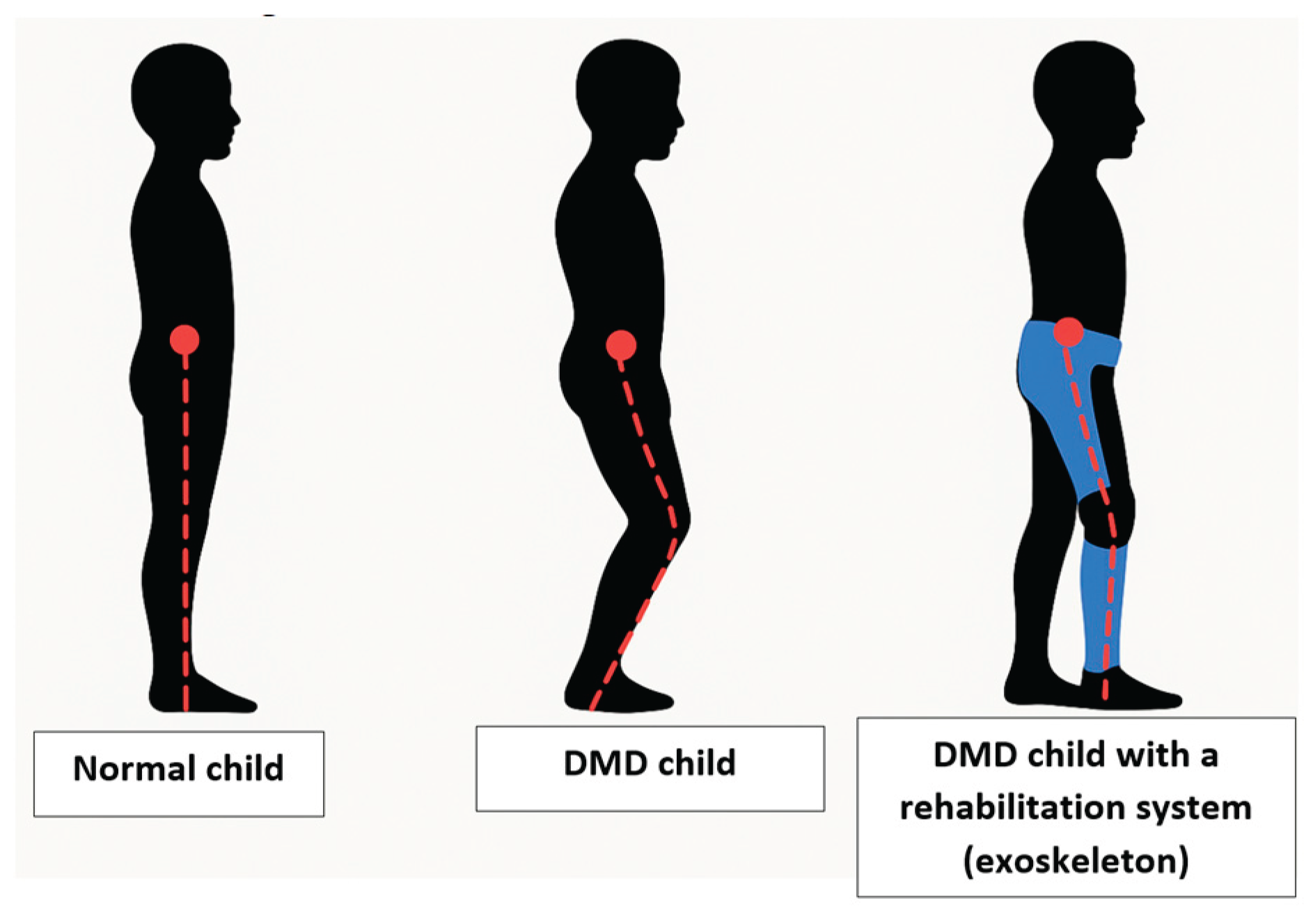
Figure 2.
Research workflow.
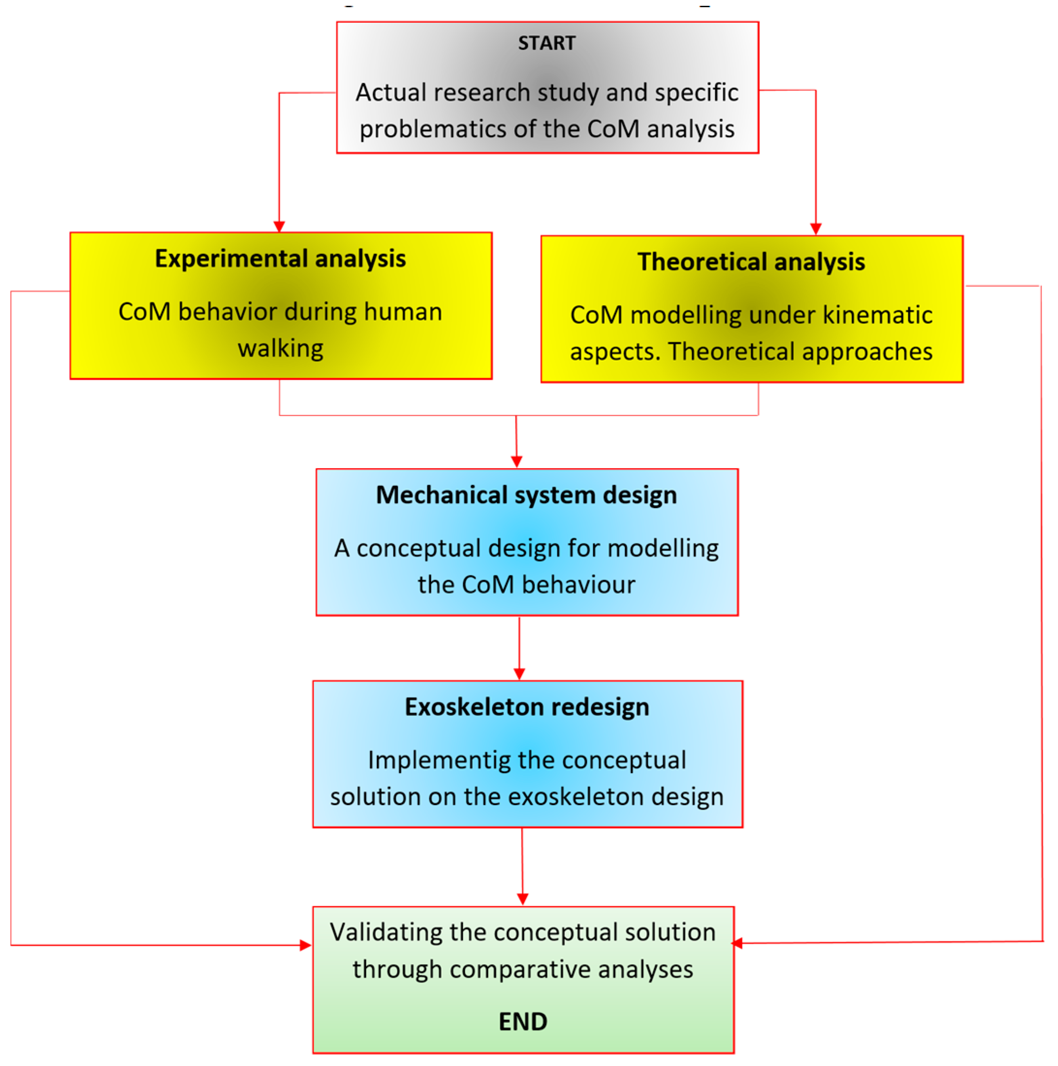
Figure 3.
Markers positions for monitoring the CoM of the analyzed human subjects.
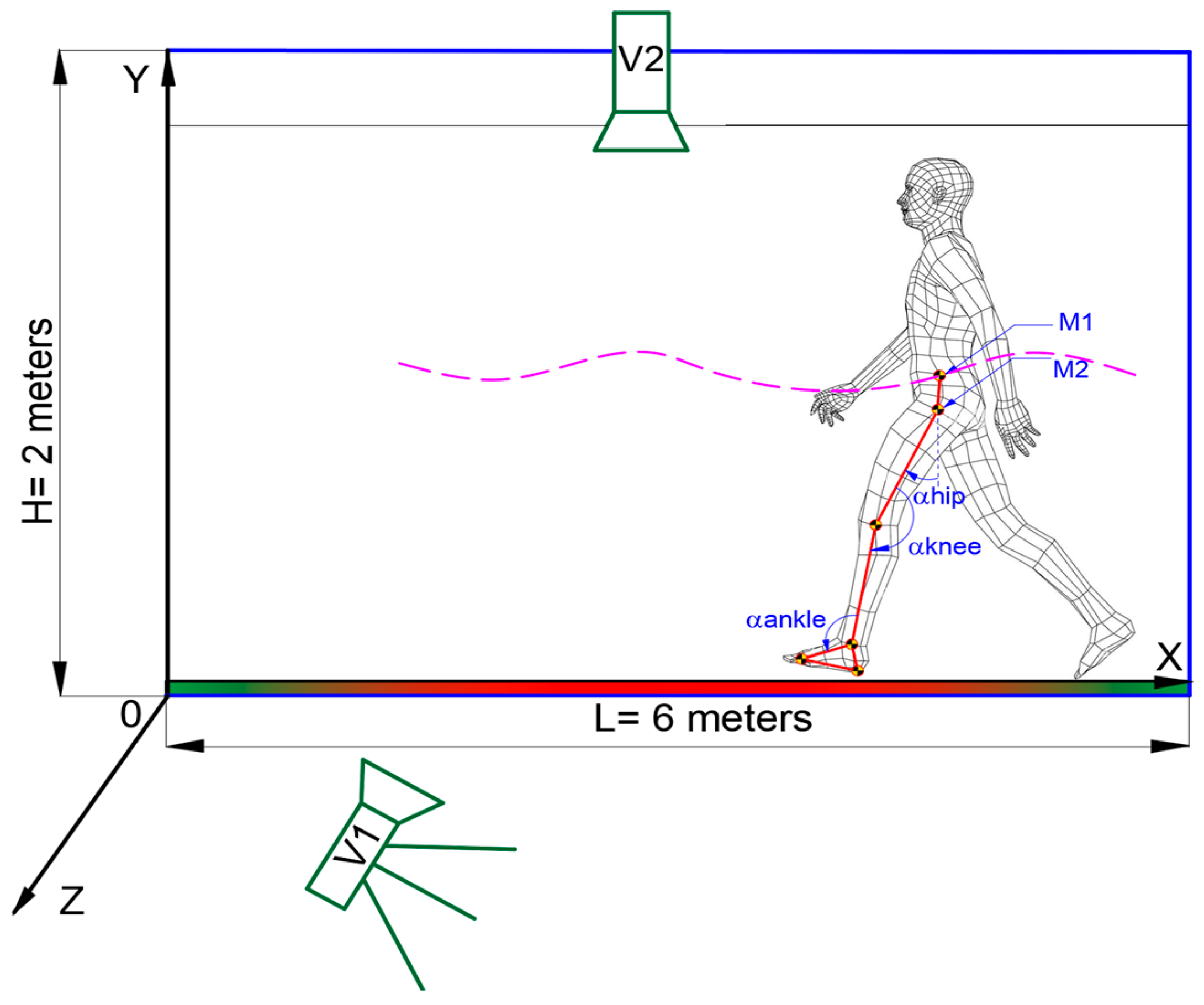
Figure 4.
Experimental tests snapshots of the analyzed cases for the CoM trajectory in vertical plane: a−healthy child; b−DMD child.
Figure 4.
Experimental tests snapshots of the analyzed cases for the CoM trajectory in vertical plane: a−healthy child; b−DMD child.
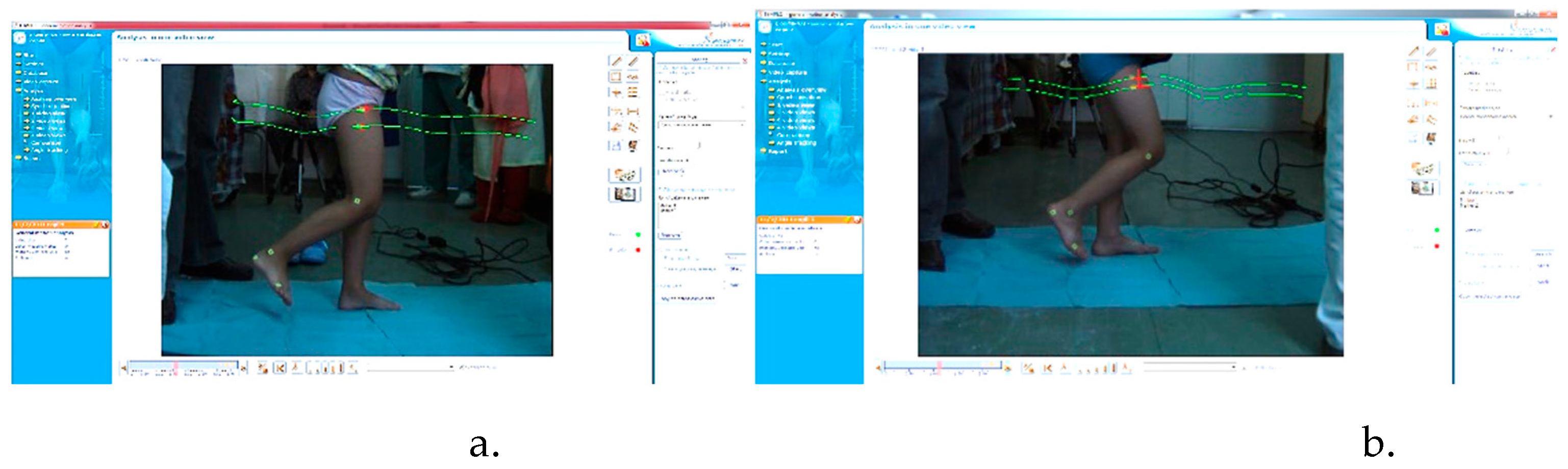
Figure 5.
Experimental CoM trajectory in transversal plane during one gait.
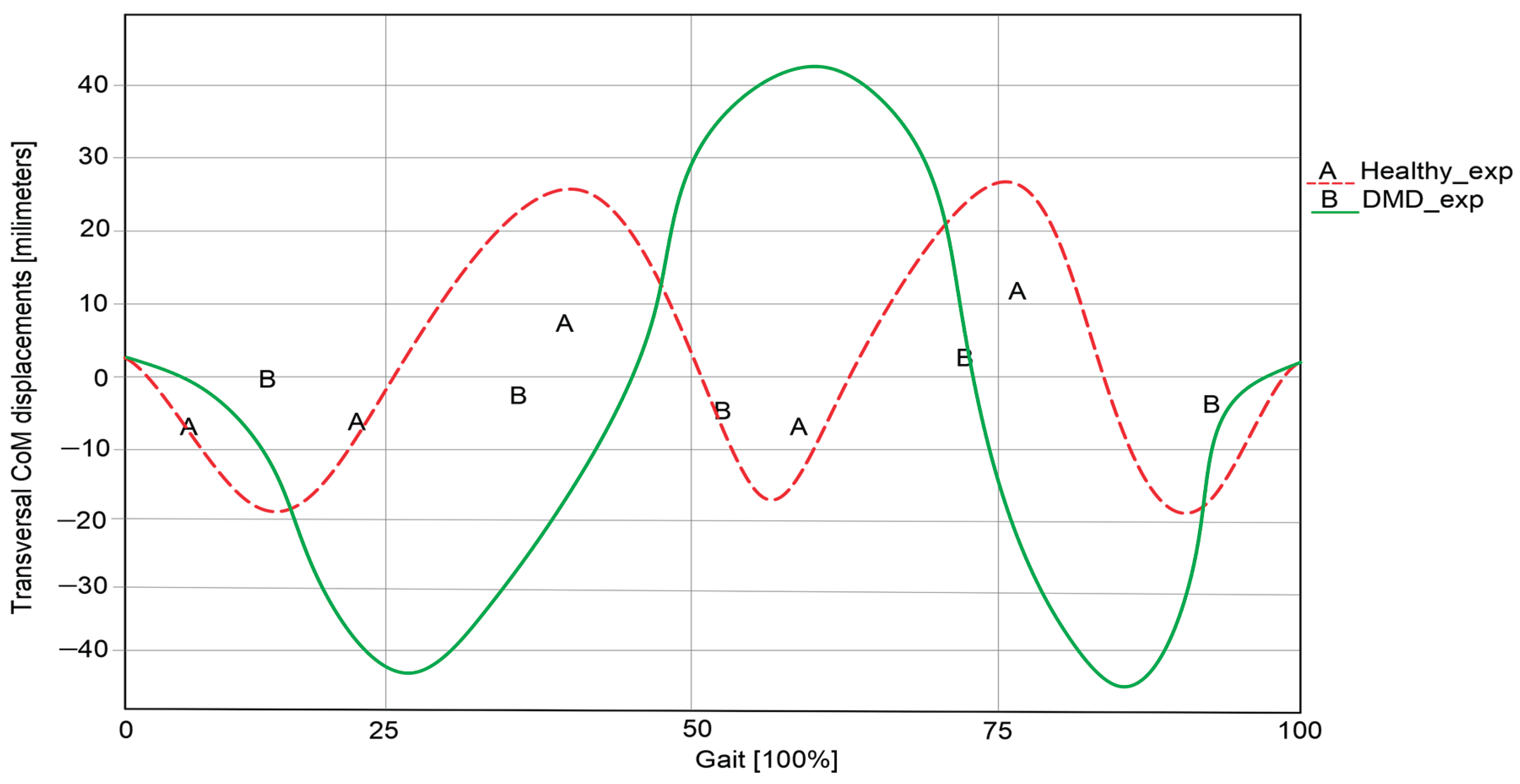
Figure 6.
Experimental CoM trajectory in vertical plane during one gait.
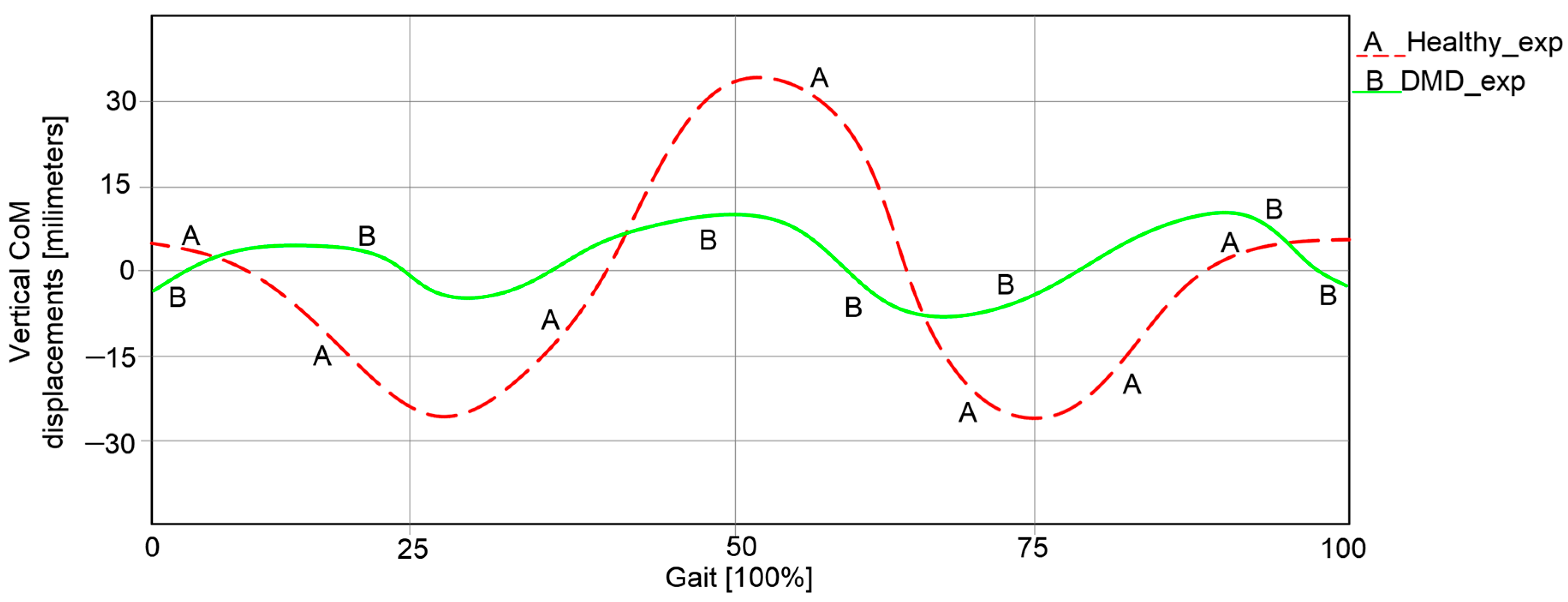
Figure 7.
Human kinematic locomotion system with an integrated CoM mechanical device.
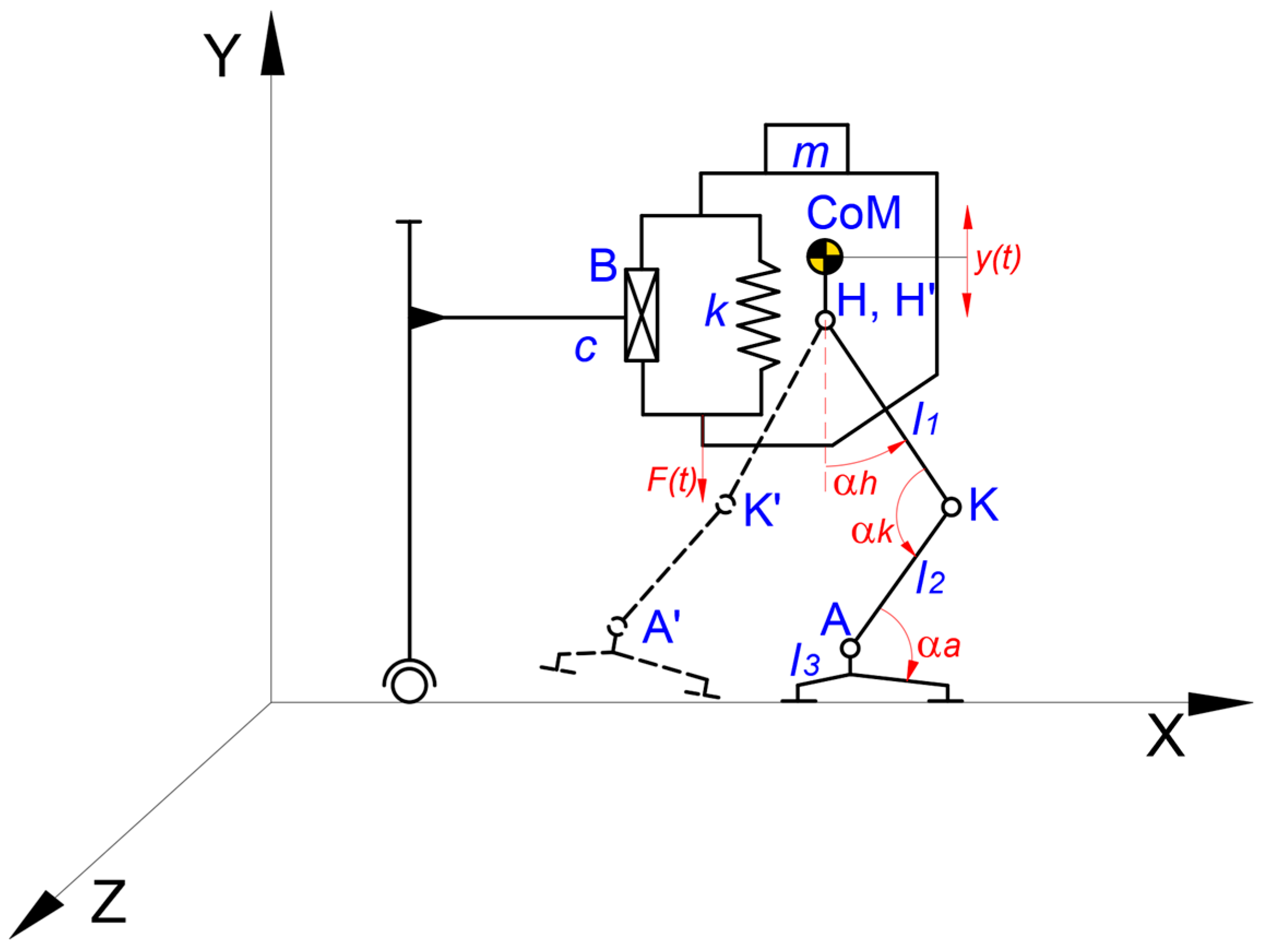
Figure 8.
Displacements of the yCoM during time (for a complete gait cycle).
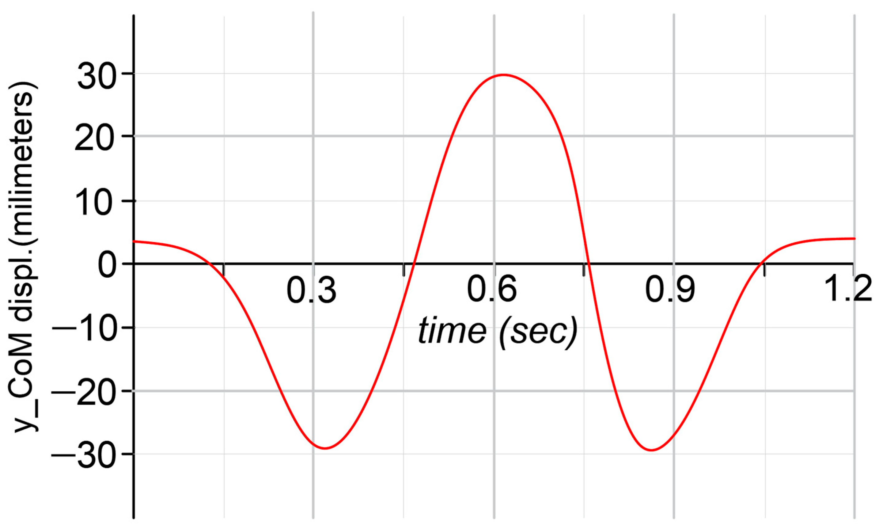
Figure 9.
A structural scheme of the proposed mechanical device for assisting the CoM behavior inside of a rehabilitation exoskeleton for a child with DMD problems: a – principle scheme; b – adopted constructive solution.
Figure 9.
A structural scheme of the proposed mechanical device for assisting the CoM behavior inside of a rehabilitation exoskeleton for a child with DMD problems: a – principle scheme; b – adopted constructive solution.
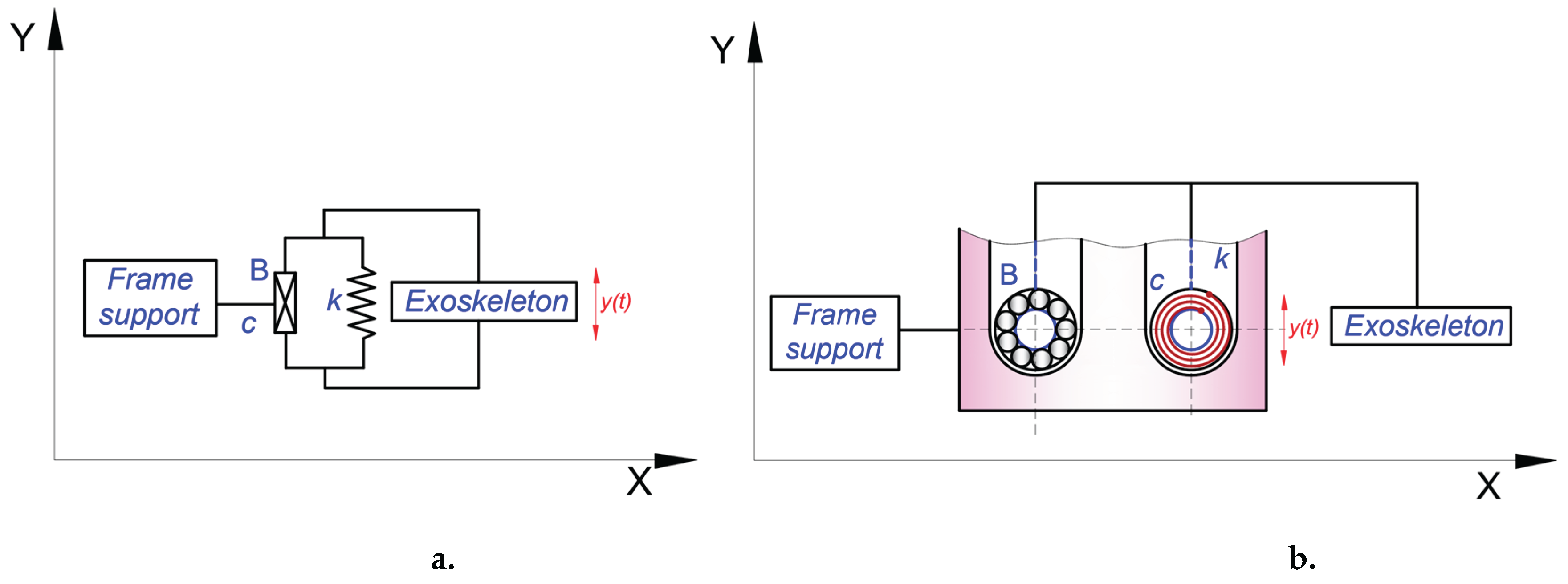
Figure 10.
Virtual model of the elastic component: a – balance spring; b- section view of the assembled housing; c – assembled elastic component; d – transparent view of the outer roller for viewing the mounted balance spring onto the inner roller.
Figure 10.
Virtual model of the elastic component: a – balance spring; b- section view of the assembled housing; c – assembled elastic component; d – transparent view of the outer roller for viewing the mounted balance spring onto the inner roller.
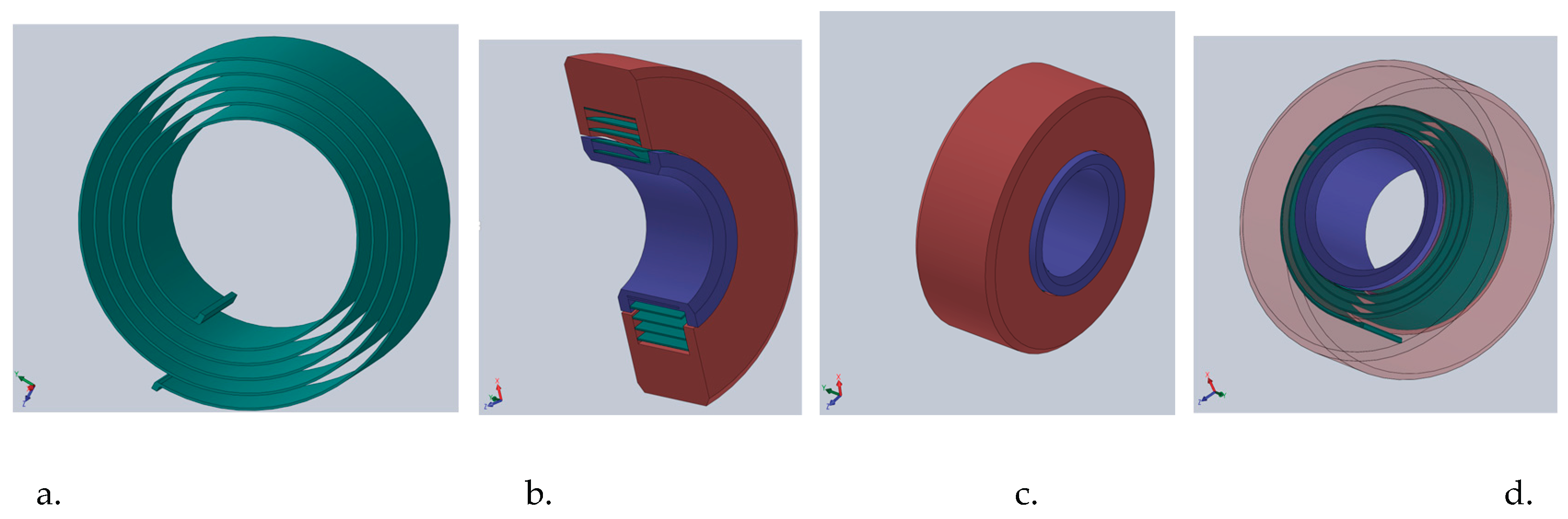
Figure 11.
The pelvic subassembly from the exoskeleton prototype with the mechanical device for assisting the CoM behavior during walking: a – the assembled virtual model; b – location of the CoM mechanical device; c – detailed view with the elastic component and the ball bearing.
Figure 11.
The pelvic subassembly from the exoskeleton prototype with the mechanical device for assisting the CoM behavior during walking: a – the assembled virtual model; b – location of the CoM mechanical device; c – detailed view with the elastic component and the ball bearing.
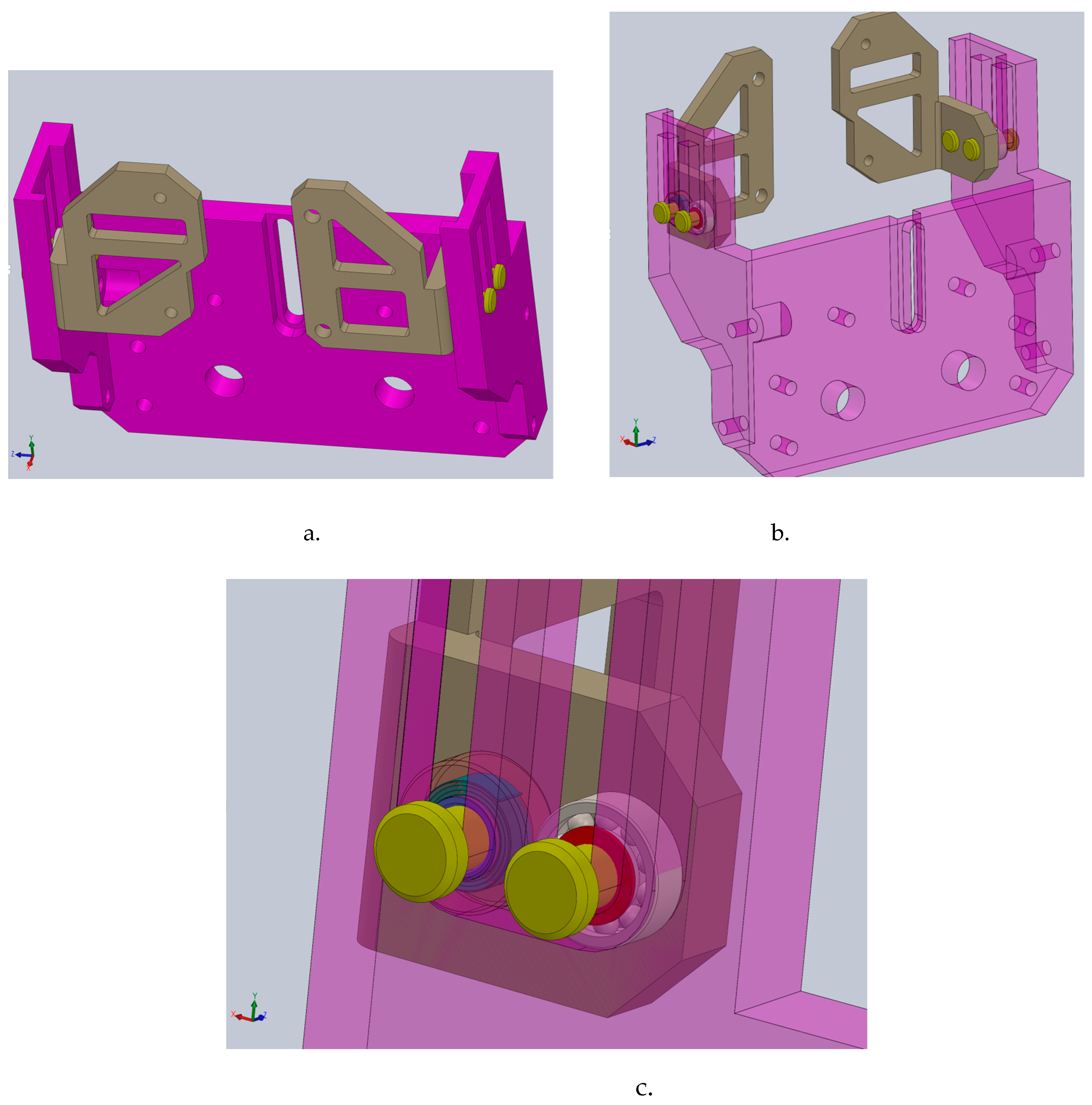
Figure 12.
The exoskeleton prototype with the mechanical device for assisting the CoM behavior during walking: a – a view with the entire virtual model assembled; b – detailed view of the mechanical device for CoM position in the entire assembly for walking assistance.
Figure 12.
The exoskeleton prototype with the mechanical device for assisting the CoM behavior during walking: a – a view with the entire virtual model assembled; b – detailed view of the mechanical device for CoM position in the entire assembly for walking assistance.
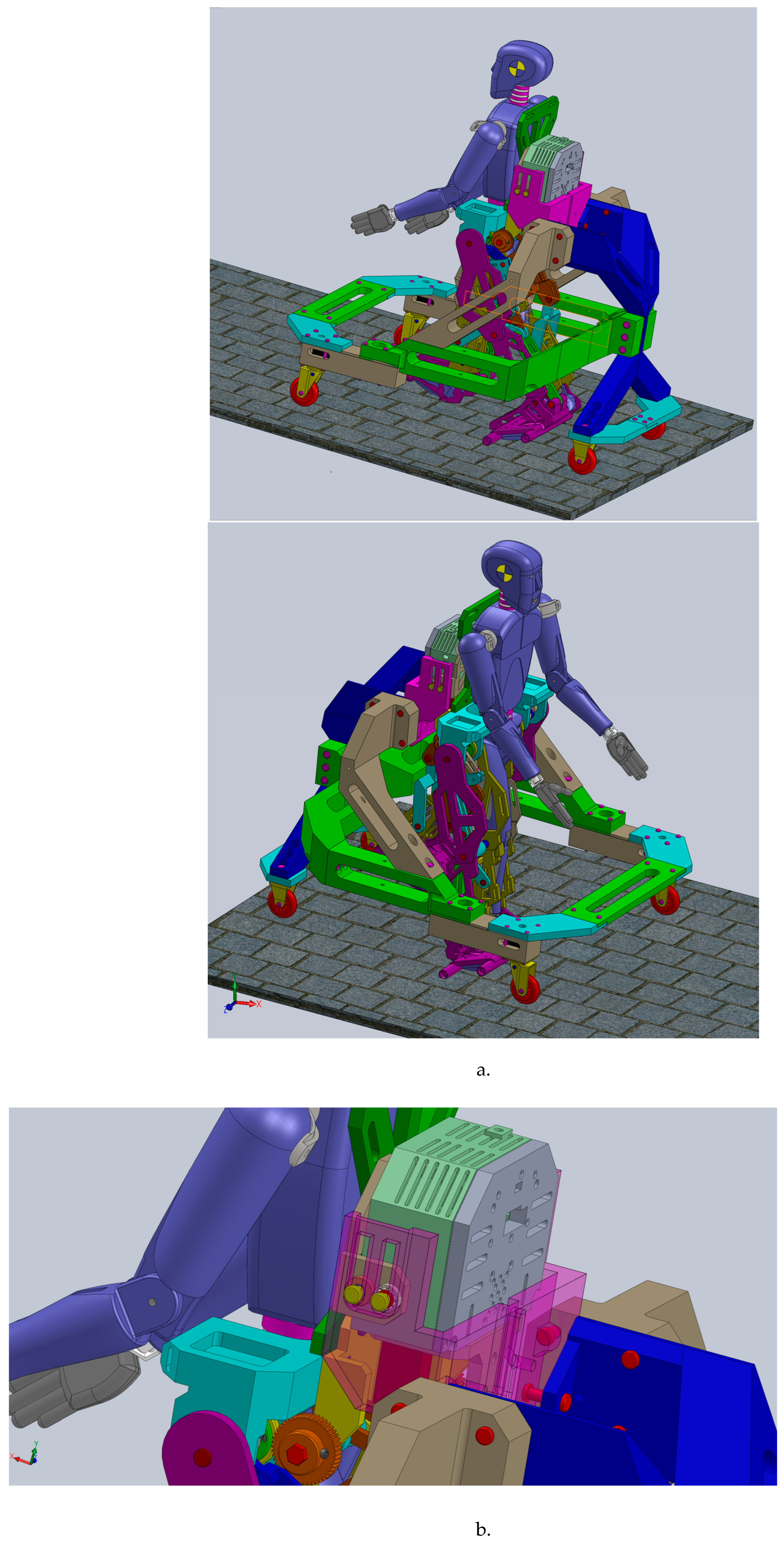
Figure 13.
The exoskeleton prototype with the mechanical device for assisting the CoM behavior during walking.
Figure 13.
The exoskeleton prototype with the mechanical device for assisting the CoM behavior during walking.
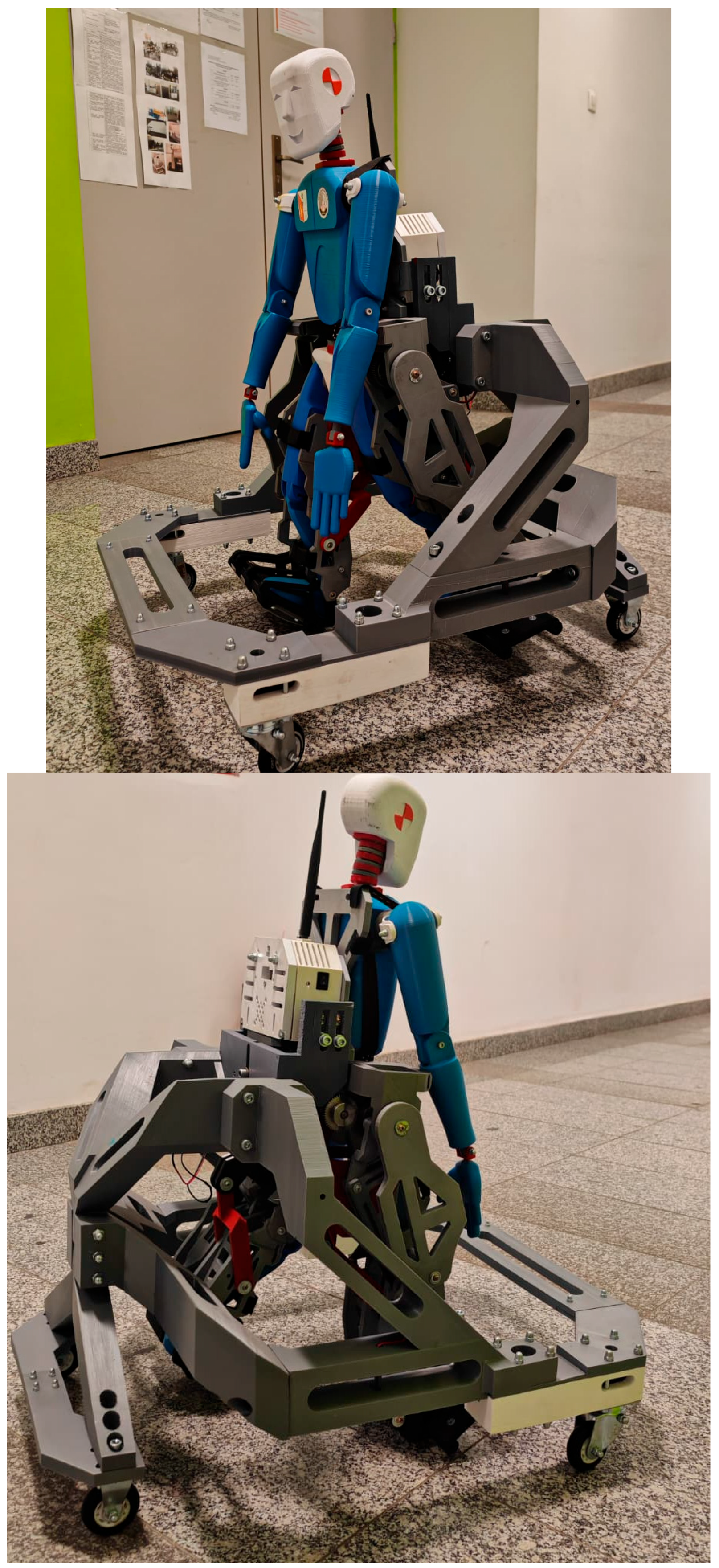
Figure 14.
A detailed view of the CoM behavior mechanical device inserted into exoskeleton structure.
Figure 14.
A detailed view of the CoM behavior mechanical device inserted into exoskeleton structure.
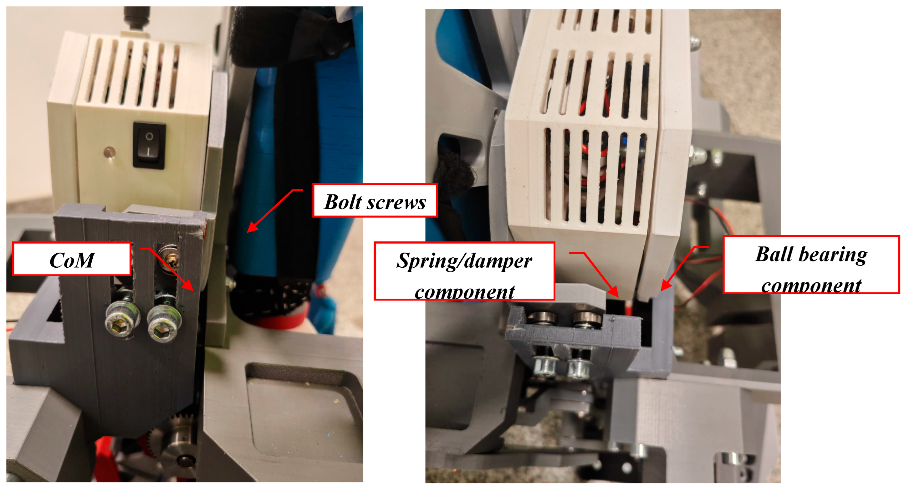
Figure 15.
A view during video motion analysis setup.
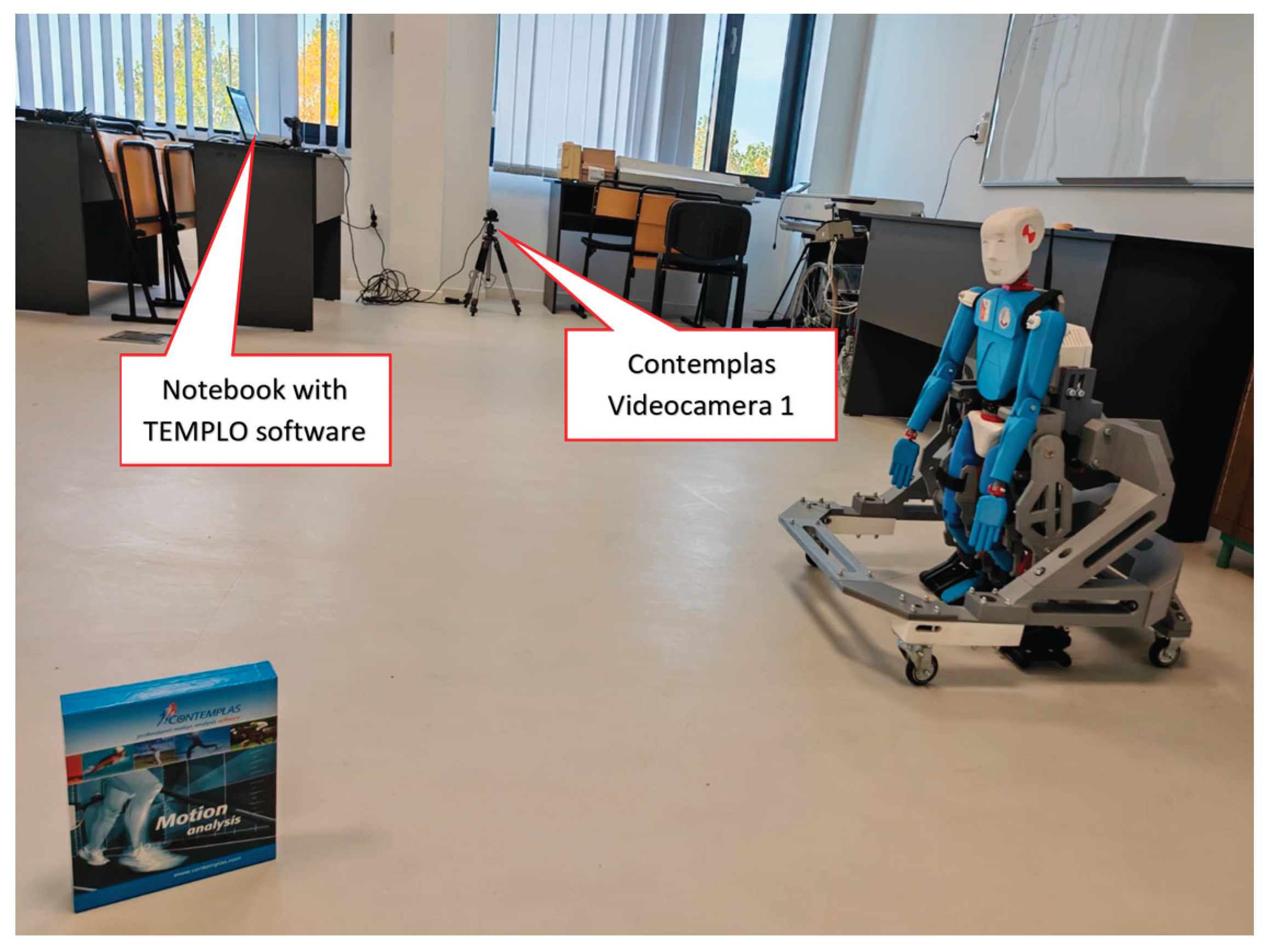
Figure 16.
Mounting the reflective markers for the experimental analysis.
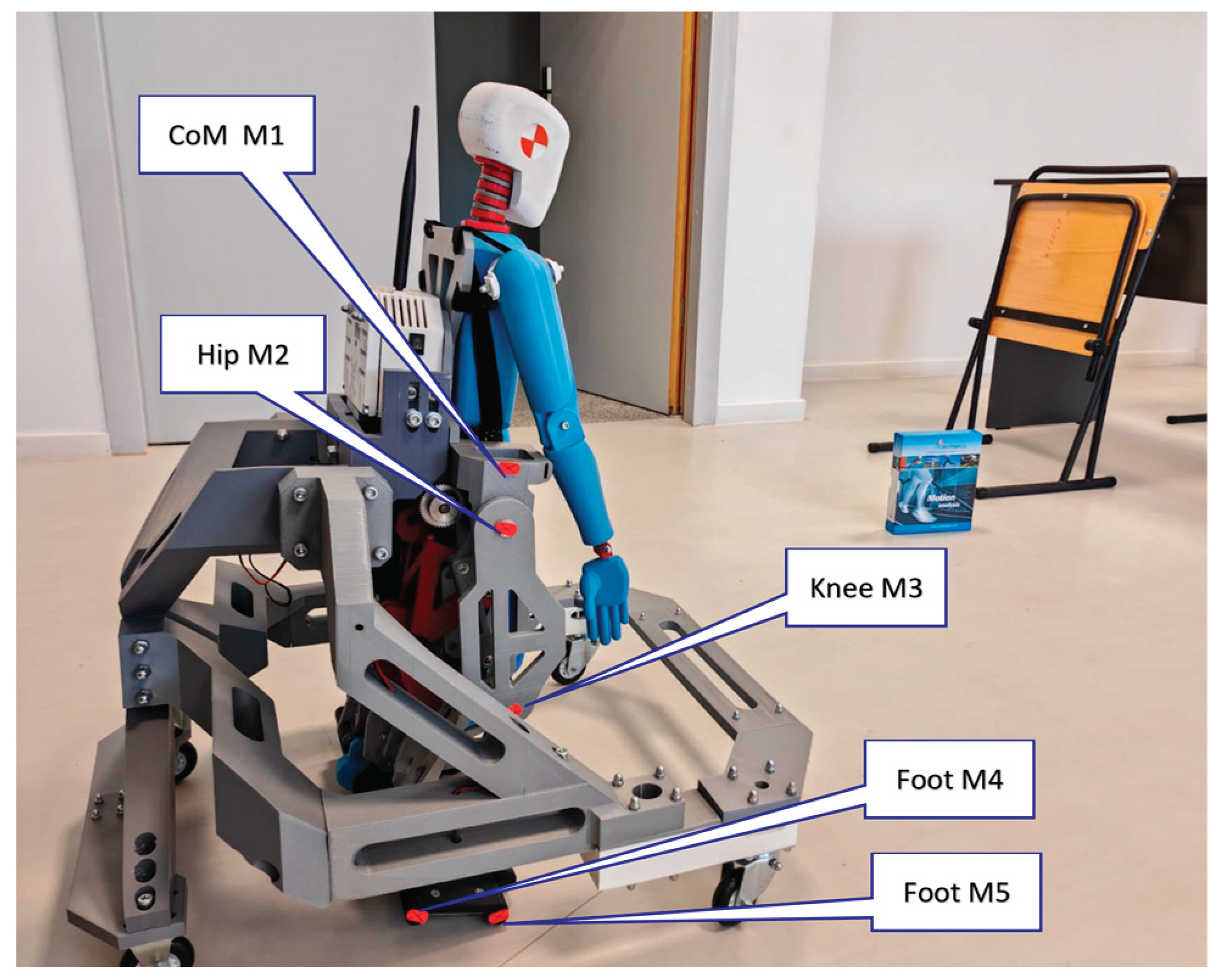
Figure 17.
The generated trajectory during a first experimental test of the CoM and hip joint.
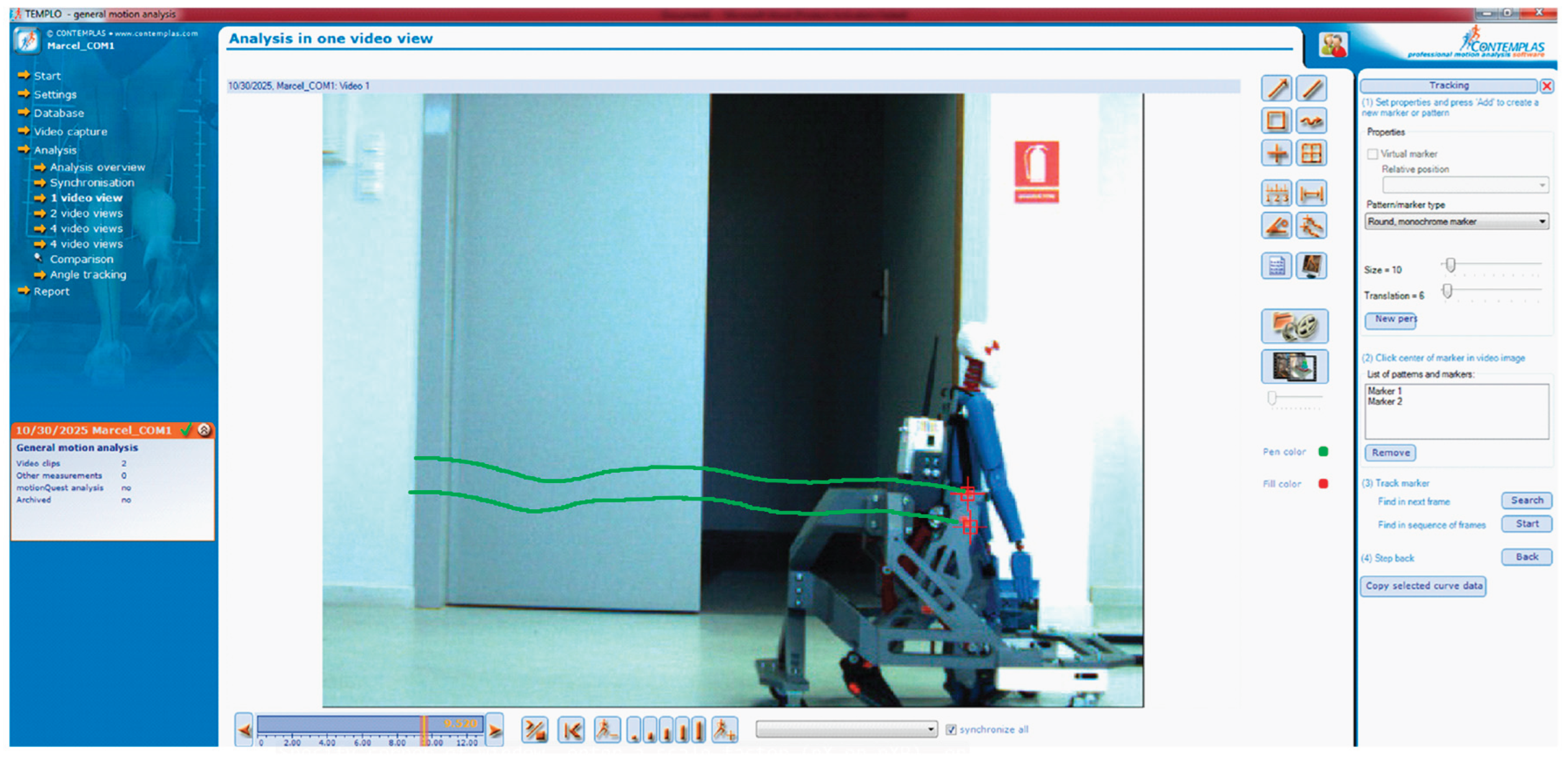
Figure 18.
Snapshots of the generated trajectory during a first experimental test of the CoM and hip joint for a complete gait.
Figure 18.
Snapshots of the generated trajectory during a first experimental test of the CoM and hip joint for a complete gait.
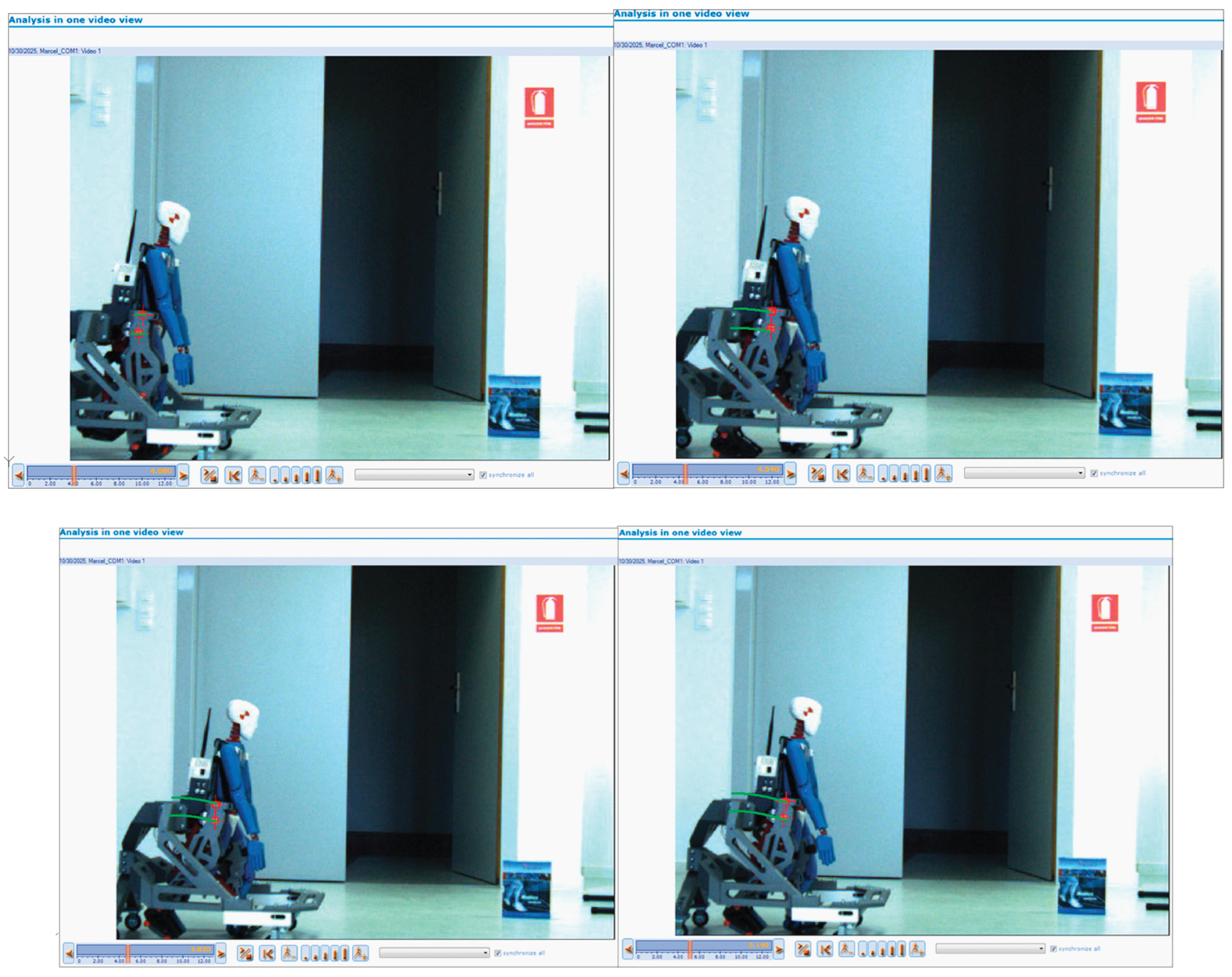
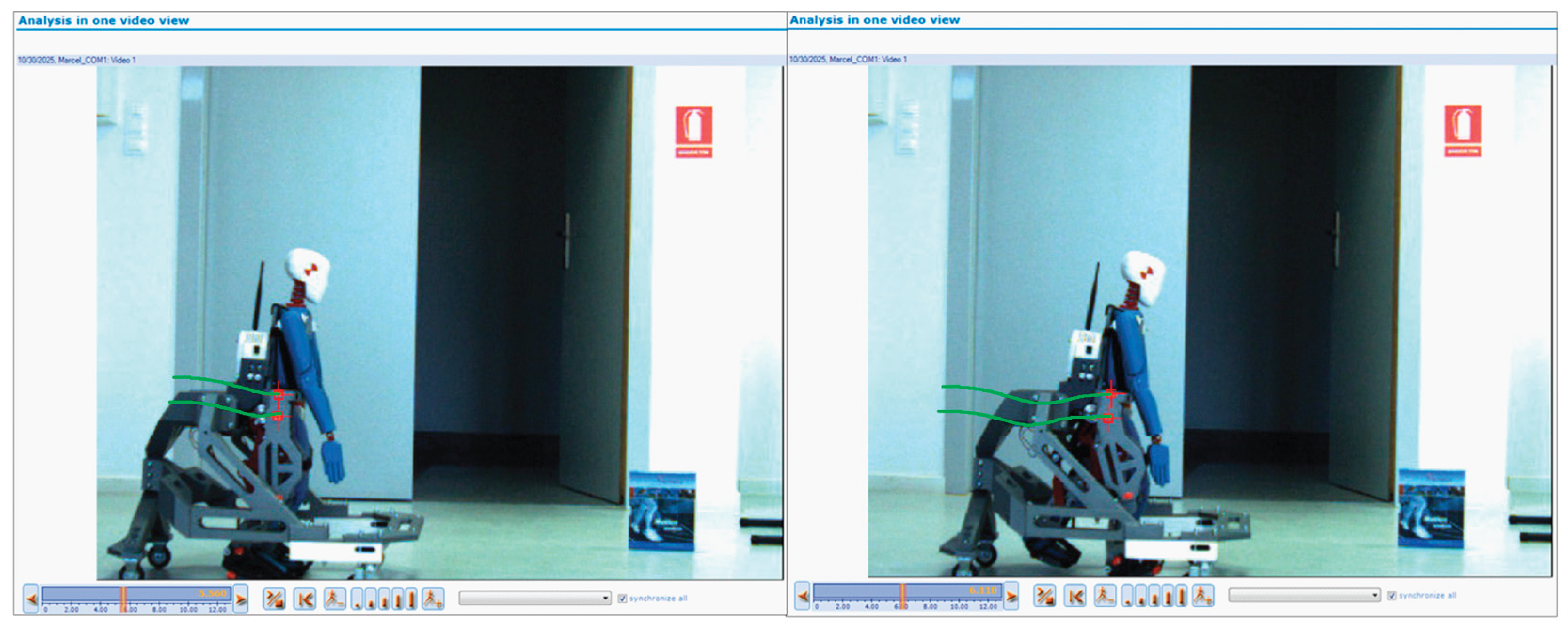
Figure 19.
Comparative analysis of the obtained results: A—healthy child (red line); B—mathematical model (green line); C—exoskeleton prototype equipped with the CoM mechanical device (blue dot line).
Figure 19.
Comparative analysis of the obtained results: A—healthy child (red line); B—mathematical model (green line); C—exoskeleton prototype equipped with the CoM mechanical device (blue dot line).
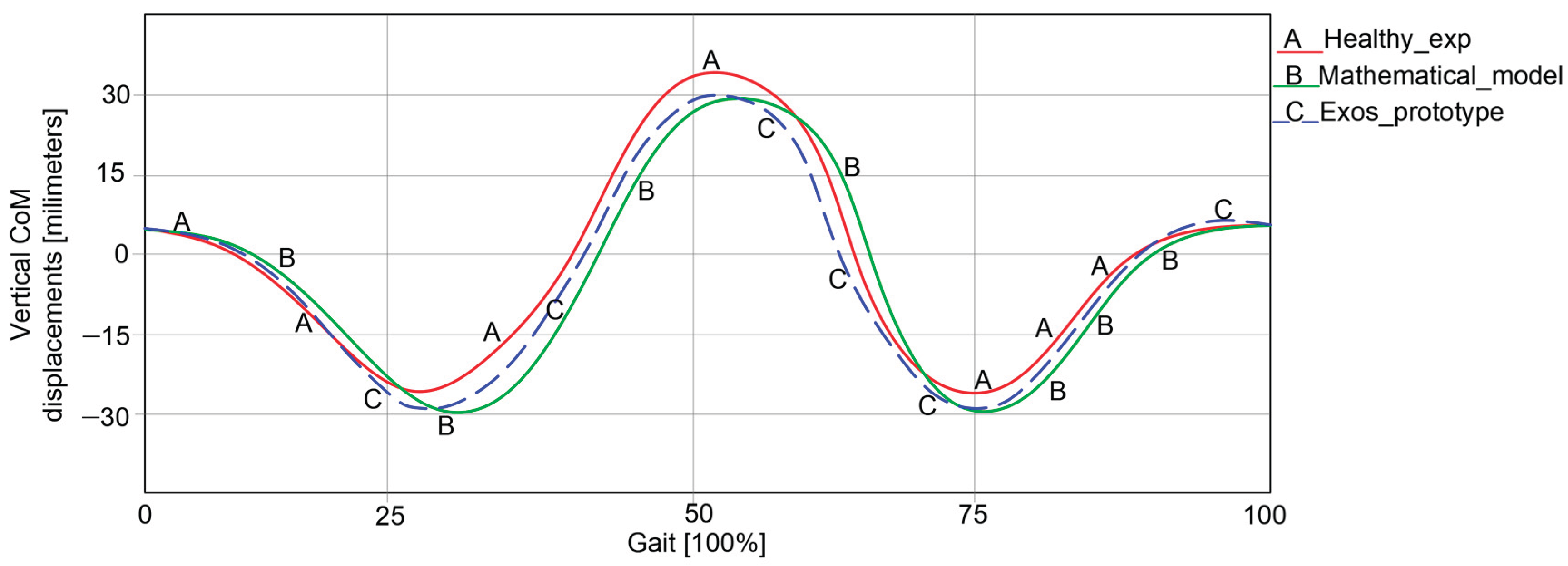

Table 1.
Summary of comparison of results in the graphs from Figure 19.
Table 1.
Summary of comparison of results in the graphs from Figure 19.
| Item | Healthy Child Experimental Analysis | Mathematical Model Numerical processing | Exoskeleton Prototype Experimental Analysis | Accuracy A [%] |
|---|---|---|---|---|
| CoM vertical displacements [millimetres] |
Max = 32.228 |
Max = 29.9 |
Max = 30.015 |
92.95 |
| Min = −28.344 | Min = −29.8 | Min = −29.748 | 94.95 | |
| Average accuracy | 93.95 | |||
Disclaimer/Publisher’s Note: The statements, opinions and data contained in all publications are solely those of the individual author(s) and contributor(s) and not of MDPI and/or the editor(s). MDPI and/or the editor(s) disclaim responsibility for any injury to people or property resulting from any ideas, methods, instructions or products referred to in the content. |
© 2025 by the authors. Licensee MDPI, Basel, Switzerland. This article is an open access article distributed under the terms and conditions of the Creative Commons Attribution (CC BY) license (http://creativecommons.org/licenses/by/4.0/).
Copyright: This open access article is published under a Creative Commons CC BY 4.0 license, which permit the free download, distribution, and reuse, provided that the author and preprint are cited in any reuse.


