
Submitted:
01 November 2025
Posted:
03 November 2025
You are already at the latest version
Abstract
The paper presents the detailed comparisons of solute macro-segregation pictures predicted by different meso-macroscopic simulations, based on the single domain enthalpy-porosity approach coupled with distinct models of flow resistance in the two-phase zone. In the first, the whole zone is treated as a Darcy's porous medium (EP model); in the other two, the columnar and equiaxed grain structures are distinguished using either the coherency point (EP-CP model) approach or by tracking a virtual surface of columnar dendrite tips (EP-FT model). The simplified 2D model of a solidifying cast in a centrifuge is proposed, and calculations are performed for the Pb-48%wt Sn cast at various hyper-gravity levels and rotation angles. It is shown that the predicted macro-segregation strongly depends on the mesoscopic model used, and the EP-FT simulation (validated with the AFRODITE benchmark) provides the most realistic solute inhomogeneity pictures. The EP-FT model is further used to investigate the impact of the hyper-gravity level and the cooling direction on the compositional nonuniformity developing in centrifuge casting. The hyper-gravity level visibly impacts the macrosegregation extent. The region of almost uniform solute distribution in the slurry zone rises with the increased effective gravity, though the solute channeling is more severe for higher gravity and rotation angles. A-channeling and V-channeling were observed for angles between the gravity vector and cooling direction lower than 120° and higher than 120°, respectively.
Keywords:
centrifugal alloy casting
; chemical inhomogeneity
; thermo-solutal convection
; multi-scale numerical simulation
; identification of different grain structure zones
; front tracking method
1. Introduction
In recent years, the need to manufacture high-quality casting products has driven the improvement of traditional foundry technologies by applying the hyper-gravity field created by centrifugal forces. The idea has emerged from the demand of the aircraft engine industry, facing the problem of low castability of lightweight titanium alloys, causing the incomplete filling of thin-walled cavities of turbine blades under terrestrial gravity. Centrifugal and Coriolis forces in the rotating mold drive the liquid metal into thin cast parts (e.g., Humphreys et al. [1]). Moreover, it has been soon revealed and confirmed by extensive experimental and theoretical research conducted in the last decades that hyper-gravity also significantly influences the melt flow and heat and solute transfer during solidification at both micro and macroscopic scales. Thus, it visibly affects a final cast’s grain structure and mechanical properties.
One of the major flaws of the alloy cast solidifying under terrestrial gravity is its chemical inhomogeneity, known as solute macro-segregation. This phenomenon is attributed to the solute segregation at the individual grains’ scale due to different solute solubility in the liquid and solid phases and then to convective transport of the excess solute, the solidification shrinkage, and the relative motion of the liquid and solid phases at the whole cast’s scale. Thus, the evolution of a non-uniform distribution of the solute concentration and highly solute-reach long and narrow channels, which post-solidification thermal manufacturing processes can hardly remove, considerably deteriorates the quality of alloy casting products.
In this context, manufacturing of metal alloy casts in the centrifugal field has attracted foundry engineers and researchers, as the high-speed rotation enhances melt flow and significantly alters the processes of heat and solute transfer at both the grain’s and the whole cast’s scales, thus changing the developing dendrite structures, solute distributions, and the macro-segregation pictures. Therefore, for the last decades, vast experimental and theoretical research has been conducted all over the world to comprehend better the role of strength and directions of centrifugal forces in complex transport processes occurring in metal alloy solidification and to search for appropriate conducting the centrifugal casting process to get the product of satisfactory grain structure and mechanical properties.
Bataille et al. [2] experimentally examined the Pb-50wt.% Sn cast’s microstructure after the centrifugal directional solidification with the constant high gravity level (over 15 times higher than the terrestrial gravity). They reported that the enhanced buoyancy decreases the primary arm spacing (PAS), yielding grain microstructures similar to those attainable in microgravity.
Zimmermann et al. [3] used the optically transparent organic alloy (Neopentylglycol-(D) Camphor) and the direct in-situ observation of dendritic structures developing during the alloy solidification at different gravity strengths with the range from 0 up to 10g. In the case of a low cooling rate and a laminar melt flow, almost the same growth velocities and primary arm spacing of the columnar dendrites were observed for all g-levels. However, with the growing cooling rate, the nucleation of many equiaxed grains is observed in the case of 10g centrifugal solidification, and the accompanied CET (Columnar-to Equiaxed Transition growth) develops earlier in both time and position than in the case of low g-values.
By the detailed metallographic examination and mechanical strength tests, Gan et al. [4] analyzed the influence of very high super-gravity (from 1000g up to 5000g) on the spatial distribution of eutectic structures in the Al-14.5Si. They reported that with the increase of the gravity strength, associated with the long-range convective transfer of the solute, the eutectic Si is visibly refined, and the tensile strength, the yield strength, and the elongation of the alloy are much higher when compared to those when solidification is conducted in the terrestrial gravity.
You et al. [5] used metallographic and electron-scanning microscopes to study the role of a very high hyper-gravity (up to 3000g), perpendicular to the terrestrial gravity direction, in the developing dendrite microstructures and the chemical inhomogeneity in the commercial Al7050 alloy. They observed diverse grain microstructures for the changing hyper-gravity levels. Thus induced, the enhanced liquid alloy convection augments the Zn, Mg, and Cu solutes concentration gradients along the direction of hyper-gravity, therefore enabling the development of columnar and equiaxed crystals of different sizes and the macro-segregation effects in various parts of the analyzed sample.
Yang et al. [6] have experimentally compared grain microstructures of Al-Cu alloy samples after the finite stage of solidification in terrestrial gravity (g) and hyper-gravity (800g). In the highly enhanced gravity, they observed solute-reach regions at the bottom and negative segregation of Cu at the top of the samples. This chemical inhomogeneity is more severe with increasing Cu solute in the analyzed alloys.
Lv et al. [7] investigated experimentally the role of horizontal centrifugation in modifying the microstructure of a wedge-shaped Al-Cu cast. A thorough analysis of measured temperatures and metallographic images of the cast microstructure and grain orientation leads them to conclude that increased centrifugal acceleration significantly decreases the average grain size and the secondary dendrite arm spacing.
Nelson et al. [8] have used high-speed synchrotron tomography and elaborated sophisticated 3D mapping to observe the evolving composition and microstructures of Al-15wt.% Cu samples during solidification in the terrestrial gravity. They have focused on the role of gravity and the direction between the melt flow and the primary dendrite growth on the evolving microstructure, fragmentation, and macro-segregation. They have concluded that the refined microstructures are obtained when the melt flow direction caused by thermal and solute buoyancy forces is the same as the temperature gradient direction.
From those mentioned above and several other research papers available in the worldwide literature involving in-situ and real-time observations of various metal alloy samplings solidifying in the enhanced gravity field, it comes out that final grain structures and thermo-mechanical properties of the cast are subject to many mold and processing factors, such as cast dimensions, direction and speed of rotation and temperature gradient, the solidification rate, the composition of the molten alloy and others. So, for a high-quality product of hyper-gravity casting, it is essential to tailor this specialized manufacturing method by continuously monitoring and optimizing its process parameters. For this purpose, a complete understanding and detailed knowledge of multi-scale heat and mass transfer processes are needed, including the role of external forces in developing chemical inhomogeneity in the final product of centrifugal casting. However, such a complete study is not possible only through cumbersome, expensive, and time-consuming experiments (based mainly on examining in-situ products). Several advanced models of computer simulation of heat and mass transfer processes occurring at the scale of individual grains (the mesoscopic scale) and the whole casting product (the macro-scale) have been developed in the last two decades to assist this cognitive endeavor significantly.
Viardin et al. [9] and Viardin et al. [10] have carried out the 2D numerical simulations of the columnar dendritic growth and microstructure developing during the directional solidification of Ti-48 at% Al. They analyzed various levels (up to 20g) and two directions of hyper-gravity, namely parallel and antiparallel to the path of primary dendrites growth. In these mesoscopic calculations, they have applied the phase-field method ([9,10]) or the simplified model ([10]), where an envelope with continuously varying solid fractions represents the complex shape of a single dendrite. The performed calculations have shown that the strength and orientation of hyper-gravity greatly influence the grain morphology and the primary dendrite arm spacing (PDAS), particularly in the case where the direction of a high-level gravity is opposite to the temperature gradient (to the growth direction). The upward melt flow around the dendrite tip, enhanced by centrifugal forces, causes unstable dendritic growth, leading to tip splitting, branching, and local changes in the dendrite growth direction.
Zhang et al. [11], using the Cellular Automaton and the Lattice Boltzmann methods, analyzed the effect of hyper-gravity on the growth of single and multiple columnar and equiaxed dendritic crystals of the Al-4wt.% Cu alloy. The results of this numerical study confirm that the primary dendrite arm spacing (PDAS) and its growth rate, the crystal microstructure, and the solute segregation strongly depend on the hyper-gravity strength and direction. When the gravity direction is consistent with the path of the primary dendritic growth, the PDAS, the dendrite growth rate, and the channel segregation are augmented with the increase of the hyper-gravity level. When the hyper-gravity vector’s direction is opposite to the primary crystal growth direction, the PDAS is significantly reduced, and the refined microstructure of a cast is obtained.
The results of these mesoscopic computer simulations of metal alloy solidification and the relevant in-situ observations show that the melt flow modulated under the hyper-gravity conditions significantly affects the grain nucleation, interface instability, constitutional undercooling, dendrite arms spacing and growth of columnar and equiaxed crystals, their migration and the CET, and thus giving the potential for grain refinement.
But the chemical heterogeneity at the scale of individual grains, inherent to the difference of solubility at the liquid-solid interface and non-equilibrium solidification, while associated with the relative motion of the liquid and solid phases (caused by thermosolutal convection, solidification shrinkage, grains sedimentation) leads to the solute macro-segregation developing in a whole cast domain containing an enormous number of grains. Here, computer simulation models used at the grain’s scale would require a tremendous and unavailable burden of computer resources nowadays. Therefore, meso-macroscopic modeling has been developed, where key calculations are performed on the macroscopic scale, and information about the developing grains’ structures is transferred to the macroscopic model through the effective properties of the two-phase region, the so-called mushy zone. Several such multi-scale computer simulation models have been proposed in the last three decades to predict compositional macro-segregation of chemical species in terrestrial gravity conditions. Macroscopic conservation equations of mass, momentum, energy, and species concentration are based on the mixture theory (e.g., Bennon and Incropera [12], Ni and Incropera [13]) or volume averaging (e.g., Beckermann and Viskanta [14]). The mushy zone is formed in non-isothermal alloy solidification, where the competing columnar and equiaxed/globular grain structures develop. Motionless columnar dendrites are immersed in a molten alloy; in the other part of the mushy zone, equiaxed/ globular grains are suspended or/and transported in the alloy melt, and the CET can develop in the proceeding solidification. Various models of the mushy zone’s permeability have been proposed and supplemented to the macroscopic calculations of the transport equations. Some researchers treat the whole two-phase region as Darcy’s porous medium using the Kozeny-Carman model of permeability (e.g., Založnik and Combeau [15], Kumar et al. [16], Cao et al. [17]), the others distinguish zones of columnar and equiaxed grains, where different models of the resistance to melt flow are applied. In many research papers, these two different grain structures are identified by the inspection of the solid fraction value in the mushy zone (e.g., Chang and Stefanescu [18], Ilegbusi and Mat [19], Vreeman and Incropera [20], Krane [21]). When it exceeds the dendrite coherency point (DCP) value, Darcy’s flow model with the permeability concept is used; otherwise, the pseudo-viscosity [18] or semi-solid medium [19] models are applied. Alternatively, Banaszek and Seredyński [22] have proposed the replacement of the DCP model used in the identification of different dendritic structures by the direct tracking of a virtual surface, being a locus of the columnar dendrite tips and moving according to the local law of crystal growth on a fixed non-structural control-volume mesh. They have compared both models in the prediction of the solute macro-segregation pictures of Pb-Sn alloys solidifying in the rectangular cavities under the terrestrial gravity and concluded that the predicted channel segregates are prone to the used control-volume mesh, the applied permeability formula, and the method of separating different dendritic structures within the mushy zone (Seredynski and Banaszek [23]).
However, the research reported so far on computer simulations of transport processes accompanying the centrifugal casting is less extensive than that concerning the process in terrestrial gravity conditions. It is mainly concerned with the pouring process; only a few research papers have addressed the issue of the effect of the strength and direction of hyper-gravity on the solute inhomogeneity developing throughout the whole cast at different stages of the centrifugal investment casting.
Daloz et al. [24] have developed a 2D axisymmetric multi-scale computer simulation model for the centrifugally cast Al-Ti cylindrical sample. The proposed simulation is based on the volume-averaged Euler-Euler two-phase approach, where macroscopic thermal and solute convection calculations are coupled with microscopic nucleation and crystal growth models. Based on the analysis of the strength of terrestrial gravity, Coriolis, and centrifugal forces, only the latter has been taken into account in the calculations. The coherency-point approach [19] has been used to distinguish the zones of stationary columnar dendrites and moving equiaxed grains. The detailed analysis of the obtained outcomes has shown the significant influence of the alloy’s initial superheating, grain growth kinetics, and the motion of equiaxed grains on the developed macro-segregation pictures in the sample. Humphreys et al. [1] have developed a comprehensive computer simulation of the mold filling and solidification of high-temperature titanium alloys under significant centrifugal forces. Their 3D computational model is based on the volume-of-fluid method for capturing a gas-liquid free surface and discretizing the transient high-velocity fluid flow, heat transfer, and solidification on finite volume unstructured meshes. Taking advantage of the developed model’s capability, the authors have focused on the formation and transport of bubbles and the air entrapments (creating shrinkage porosity) in the investment casting of the turbine blade and reported a good agreement of the numerically predicted macro-defects and their experimental pictures. Finite element software and experimental measurements (X-ray flaw detection, fluorescence analysis, and electron microscope scanning) have been used by Yang et al. [25] to study the issue of the role of centrifugal forces on the filling process, microstructure and mechanical defects in investment casting of the Nb-TiAl alloy for turbine blades. Showing good consistency, the calculations and experimental results confirm that the centrifugal casting blade has fewer shrinkage porosities and cracks and a much finer microstructure. However, the paper has not addressed the role of thermosolutal buoyancy and the Coriolis acceleration in the development of macroscopic chemical inhomogeneity. Battaglioli et al. [26] have developed a 2D computer simulation model for predicting the influence of gravity strength on the evolution of fluid flow, temperature, and grain structures during the directional solidification of Ti-Al alloy on a centrifuge. The model is based on a single set of transport equations in the solid-liquid mixture, discretized on a structural control-volume mesh in the plane perpendicular to the rotation axis. The front tracking procedure is applied to trace the developing columnar dendrites zone, where the porous medium model is exploited. The resulting numerical predictions for various angular velocities and different lengths of the centrifuge arm show the augmented thermal convection of the melt with an increasing level of centrifugal acceleration and the negligible impact of Coriolis forces on the melt flow when compared to the buoyancy encouraged by the centrifugal acceleration. This research study omitted the solute convection, and the macro-segregation is not analyzed. Tao et al. [27] have developed the 3D macroscopic model for the centrifugal investment casting of large-size titanium alloy components. The proposed computer simulation is based on discretizing macroscopic mass, momentum, and energy transport equations on a non-conformal finite difference mesh. The authors have focused on analyzing the centrifugal filling process and developing shrinkage holes in the titanium alloy casing. Comparing the numerical simulation results with the X-ray pictures, they conclude that the centrifugal casting process does not show visible improvements in shrinkage defects compared to the gravity casting. The 3D numerical simulation of the directional columnar solidification of Ti-Al alloys (consistent with the configuration of ESA GRADECET experiments) is presented by Fernández et al. in [28] and [29]. The applied volume-averaging model accounts for thermo-solutal convection, centrifugal, and Coriolis accelerations when the temperature gradient along the cylindrical sample is antiparallel to the total apparent gravity (sum of centrifugal and terrestrial gravity). The Kozeny-Carman hydrodynamic permeability of the columnar mushy zone and Boussinesq’s model for thermo-solutal buoyancy forces have been adopted, along with the assumption of even densities and specific heats of the liquid and solid phases and the equilibrium model of microscopic solute diffusion (the lever rule model). The calculations show that Coriolis acceleration, although weak, breaks the symmetry of flow, visibly changing the aluminum segregation picture, and these changes are intensified with the centrifugation strength level. The research is, however, restricted only to the development of the columnar dendrites during directional solidification. Lv et al. [7] have presented the numerical and experimental analysis of the mold-filling process and solidification of a wedge-shaped Al-Cu cast under horizontal centrifugation. Their micro-macroscopic model is based on the simulation, where the cellular automaton method is adopted to calculate the grain nucleation and coupled with the finite element calculations of macroscopic transport processes. The presented parametric analysis is concentrated only on the impact of centrifugal forces on the cast’s microstructure changes and confirms that the rotation speed’s increase and the higher cooling rate cause the reduction of grain average sizes and the secondary dendrite arm spacing, whereas the mold’s increased preheat temperature gives the opposite effect.
The combined experimental research and computer simulations have led to significant progress in understanding the role of enhanced melt flow in a centrifuge. Despite these two-decade efforts, more still has to be done to achieve a better quantitative understanding of complex multi-scale processes deciding about grains’ micro and macro structures of hyper-gravity casting products. Among still open scientific questions, there is the influence of the interaction between the enhanced flow of melt and the Coriolis acceleration on convection and the growth of solidification microstructures [9,10,30], the mechanisms behind columnar crystals progress [5], and the macro-segregation developing at different hyper-gravity casting stages [6,28,30]. Also, since numerical modeling is a primary potential source of valuable information on enhancing the reliability of the whole casting process, improving the accuracy and trustworthiness of multi-scale computer simulations of solute segregation under the centrifugal and Coriolis forces remains a challenge. The enhanced mesoscopic simulations [9,10,11], based on the Phase-Field Method or the Grain’s Envelope Model [9,10] or the coupled Cellular Automaton and Lattice Boltzmann methods [11] give a deep insight and much better understanding of the impact of the strength and orientation of hyper-gravity and the augmented melt flow on the PDAS, the growth of single and multiple columnar and equiaxed dendritic crystals, and the other micro and mesoscopic characteristics of the mushy zone. On the other hand, the above-discussed combined meso-macroscopic simulations of centrifugal casting are mostly restricted to the analysis of the mold-filling process and mechanical defects (e.g., [7,25,27]), and to the directional solidification with the imposed thermal gradient direction (e.g., [26]); do not take into account the terrestrial gravity (e.g., [24]), Coriolis acceleration (e.g., [24,25]), the thermo-solutal buoyancy (e.g., [7,25,26,27]) and the different dendritic structures and the CET developing in the mushy zone (e.g.,[28,29]).
So efforts should be continued to develop further advanced computer simulations involving more accurate predictions of the solute macro-segregation and channeling phenomena under hyper-gravity, where the melt flow process is more complex and changeable than in gravity casting, and thus to frame reliable correlations between super-gravity forces and the resulting grain structures and chemical and mechanical properties of the centrifugal casting product.
The presented paper is the authors’ contribution to this up-to-date research area, in which the alternative computer simulation of the meso-macroscopic solute segregation evolving in a metal alloy cast during centrifugal solidification is proposed. The simulation, based on the coupling of the single-domain enthalpy-porosity method with the front tracking approach (to distinguish different dendritic structures in the mushy zone), is used for the first time in the detailed study of the solute inhomogeneity in the hyper-gravity conditions. The simplified 2D model of the representative rotating plane is developed on the basis of the thorough analysis of all forces acting on a cast in the centrifuge and their projections on the plane. To calculate mass, momentum, energy, and solute transport within this domain, the EP-FT model proposed in [23] has been extended by taking into account the centrifugal and Coriolis forces and performing calculations on general unstructured triangular control-volume collocated meshes. An in-depth parametric study has been carried out involving the impact of the cooling direction, gravity strength, and orientation on the development of the macro-segregation pictures, and the tendency to form freckles in solidifying Pb-Sn alloy castings. Moreover, the same calculations have been performed with the commonly used single-domain hybrid model, based on the coupling of the enthalpy-porosity model with the coherency point concept, and the predicted macro-segregation and channeling have been compared, and their similarities and differences widely discussed.
2. Mathematical and Computational Model
Macroscopic calculations of binary alloy centrifugal solidification are often built on the single continuum enthalpy–porosity model utilizing the classical two-phase mixture theory (e.g., [12,13]). During the cooling and solidification of an alloy’s cast, the two-phase zone (mushy zone) evolves, usually containing two distinguished regions of columnar and equiaxed grains. The former, having a strong directional nature, appears as a dense crystalline-like matrix filled with inter-dendritic liquid. In the equiaxed zone, grains freely grow, mutually influence, and move in the melt, and the CET phenomenon might occur. To account for different resistances to the melt flow occurring within these two diverse dendritic structures, Darcy’s porous medium model is commonly used in the columnar dendrite zone, whereas the slurry medium model is applied to the equiaxed grain zone. Therefore, it is necessary to distinguish regions of different grain structures in the computational model before applying distinct descriptions of the flow conditions. Two methods have been used to identify grain regions of varying flow conditions; they are coupled with the enthalpy-porosity model. The first one is the commonly used coherency point approach (e.g., [19,20,21]), and the computational model is further referred to as the EP-CP (Enthalpy Porosity- Coherency Point). The second one, further called the EP-FT (Enthalpy Porosity – Front Tracking), involves the front tracking procedure to trace the envelope of columnar dendrite tips on finite volume meshes (e.g., [22,23,26,31,32,33]). The macro-segregation and channeling pictures developing in the centrifugal investment casting predicted by the EP-CP and EP-FT models are compared in this research.
2.1. Macroscopic Conservation Equations
A single set of the macroscopic conservation equations of mass, momentum, energy, and the solute transport in the liquid-solid mixture appears as
V, T, and C are the velocity vector, temperature, and solute concentration, respectively. Thermo-physical properties: ρ, k, c, μ, L, and D denote density, thermal conductivity, specific heat, dynamic viscosity, latent heat of fusion, and solute mass diffusivity, respectively. Indices S and L refer to the solid and liquid phases. g and f are phase volumetric and mass fractions, respectively; stands for the switching function, which equals 1 in the columnar dendrites zone and 0 elsewhere.
According to the mixture theory, the velocity, thermal conductivity, overall solute concentration, and solute mass diffusivity of the liquid-solid mixture are given by:
where CL and CS are the average solute concentrations, and DL and DS are the solute diffusivities in the liquid and solid phases, respectively.
The volumetric sources, FV, in Eq. (2) are given by
The first and second terms in the square brackets refer to thermal and solute buoyancy forces described by the commonly used Boussinesq’s natural convection model. In a stationary coordinate system, they are multiplied by the terrestrial gravity acceleration vector, g, and constitute the gravity force, Fg. The second and third terms in the curly brackets express the centrifugal, Fcf, and Coriolis, FC, forces.
2.2. Simplified 2D Geometrical Model of the Volumetric Forces
The volumetric forces acting on a liquid volume in the rotating frame are three-dimensional; the terrestrial gravity works in the vertical direction, centrifugal acceleration acts radially concerning the centrifuge axis, and the Coriolis force operates in the horizontal planes.
The gondola with the furnace and the sample, mounted at the end of the rotating arm (Figure 1), rotates with the angular velocity, ω, around the axis Z. The rotation angle of the gondola, α, depends on the ratio of the centrifugal force and the gravity force and can be derived with the formula
The resulting (acceleration) force, Fr, is the sum of the centrifugal, Fcf, and gravity forces, Fg, and is applied to the mass center of the gondola.
The rotation rate, ω, and the distance from the axis, R, are adjusted to ensure the required gravity acceleration level. Three values of gravity acceleration are considered: 1g, 5g, and 15g. For the first one, treated as the reference case, the rotation speed is obviously equal to 0.
In the presented study, centrifugal casting in a simplified layout is considered. The sample is positioned in the center of the gondola. The cuboid shape of the mold is assumed. The basic orientation of the sample is presented in Figure 1, according to the Cartesian coordinate system x’, y’, z’ (Figure 1a), fixed with the gondola, rotating around the axis Z. The length of the edge parallel to the z’ axis is much lower than other dimensions of the cavity, so the 2D geometry of the computational domain is assumed. Additionally, the interactions of the molten alloy with walls parallel to the x’-y’ plane are omitted, and the fluid velocity components in the z’ directions are set to zero.
In this paper, the relation between the direction of cooling and the resultant acceleration force is investigated, so various orientations of the sample are considered. To accomplish various heat dissipation directions, given with Q, the sample is rotated around the axis perpendicular to the x’-y’ plane and crossing the central point of the sample, marked as the rotation axis in Figure 1b. For each case the rotation angle, β, is measured between the modified direction of the dissipated heat transfer, Q, and the resulting force, Fr, as presented in Figure 1c, and it is considered as a multiple of a 30-degree angle. The limiting values of angles 0° and 180° correspond to the cooling from the bottom and top, respectively. The size of the considered domain is 0.1 m in the x-axis direction and 0.06 m in the y-axis direction (Figure 1c). The new coordinate system, namely x, y, z, describes the orientation of the system relative to the acceleration force.
The first and second terms in the curly brackets in Eq. (9) refer to the gravitational acceleration and the centrifugal forces, respectively, and their influence can be described with the resulting (acceleration) force, Fr.
The Coriolis force (the last term in Eq. (9)) may act outside of the plane x-y, so to account for the impact of that force in the considered 2D geometry, it is necessary to take the components of the Coriolis force cast in the x-y plane. However, for the highest enhanced gravity acceleration, 15g, and the assumed process parameters, ω = 30 rad/s, R = 2.42 m, and assumed maximum molten alloy velocity Vmax = 0.1 m/s, the Coriolis force magnitude is comparable to the gravity force, and 15 times lower than the resulting force. So, in the simplified analysis, neglecting the Coriolis force is justified.
2.3. Identification of Zones of Different Grain Structures
Two different approaches are used to identify zones of prevailing distinct grain structures within the mushy zone. The first one is the dendrite coherency point model (DCP), which is based on continuously examining a solid fraction value in the mushy zone during developing solidification. Darcy’s flow model with the permeability concept is used when the solid fraction exceeds a critical value, generally accepted as equal to the solid fraction at the temperature at which the growing dendrites begin to impinge upon each other and form the stationary coherent dendritic network. Otherwise, in the zone where small equiaxed dendrites float in the alloy melt, the slurry model is adopted. This approach has been commonly used in meso-macroscopic computer simulations of metal alloy solidification under terrestrial gravity (e.g., [18,19,20,21,22,23]) and by Daloz et al. [26] in the numerical analysis of solute segregation in the centrifugally cast Al-Ti cylindrical sample. According to this methodology, the porous and slurry regions are identified with the switching function, Ṽcoh, which depends on the solid fraction according to the formula (e.g., Chang and Stefanescu [18])
where gs,coh is the volumetric fraction of the solid phase when the grains start to impinge.
The main uncertainty arising when using the DCP model concerns the reliable estimation of the packing solid fraction value at the dendrite coherency point. The literature review shows that because of the lack of experimental data for various metal alloys, some authors misuse the DCP value determined experimentally by Arnberg et al. [34] for only aluminum-based alloys, while others set its value arbitrarily. This parameter is also known as the coherency solid fraction (e.g., Ilegbusi and Mat [19]), and is referred to as gs,coh in this paper. The DCP solid fraction, gs,coh, strongly depends on the alloy composition (e.g., [34,35]), and its assumed value has a significant impact on numerically predicted solute concentration fields and macro-segregation pictures (e.g., [20,21]). Moreover, Banaszek and Seredyński [22] have shown that the use of the iso-line of constant solid packing fraction for distinguishing different grain structures is inaccurate, particularly at early stages of solidification when the formation of channel segregates develops much earlier than the CET appears, i.e., for smaller values of the solid fraction.
An alternative method for identifying zones of different dendritic structures is based on direct tracking of a virtual surface, being a locus of the columnar dendrite tips and moving on a fixed control-volume mesh during proceeding solidification according to the assumed crystal growth kinetics. This approach, originated by Browne and Hunt [31] for the case of purely diffusive alloy solidification, has been further extended to modeling columnar and equiaxed binary alloy solidification driven by natural thermal convection [32] and thermo-solutal convection [33] on 2D structural control-volume meshes. Recently, Seredyński and Banaszek [23] have generalized the front-tracking procedure to 2D unstructured control-volume meshes and used it to analyze the role of different permeability laws and various microstructure characteristic lengths on the numerically predicted solute macro-segregation developing during solidification of Pb-Sn alloys in the terrestrial gravity conditions. Battaglioli et al. [26] have applied the front-tracking method in their 2D computer simulation of centrifugal directional solidification of Ti-Al alloy to study the role of enhanced gravity on the evolution of fluid flow, temperature, and grain structures. Their model is, however, restricted to a structural control-volume mesh and does not involve the solute transport, so the solute macro-segregation is not addressed.
In the presented study, for the first time to the authors’ best knowledge, the front-tracking approach, coupled with the macroscopic description of heat, momentum, and solute mass transport phenomena driving the binary alloy solidification, is used to address the issue of the role of hyper-gravity acceleration in the development of chemical inhomogeneity in a solidifying cast.
The main novelty of the EP-FT simulation model lies in tracking the envelope of columnar dendrite tips on a fixed control-volume unstructured mesh at the end of each subsequent calculation cycle of the transport processes conducted using the enthalpy-porosity (EP) model. This hypothetical interface of columnar dendrite tips is represented by a series of linear segments connected with massless markers, as shown in Figure 2a. An i-th marker’s initial location, , is known from the previous time step; the marker moves in the normal direction to the front towards the bulk liquid, according to the determined local undercooling, ΔT, and the assumed columnar dendrite growth law. The marker’s new position is determined as and a new shape of the front is obtained by the interpolation between new locations of the markers (Figure 2a). In the presented calculations, the columnar dendrite tip velocity, Vtip, is assumed to be independent of the acceleration level and is determined using the Kurz-Giovanola-Trivedi law [36] and the least-square approximation to get for the further analyzed Pb-48wt.% Sn alloy.
The front-position-based switching function, Ṽft, is related to the position of the columnar front and is defined at a consecutive time step as the ratio between the dashed volume and the whole corresponding control volume (Figure 2b). Control volumes crossed by the front have properties of both the slurry and porous media. The source terms in the momentum balance equation, Eq. (2), are activated in this region with the appropriate weights depending on the Ṽft function. Based on the actual position of the columnar front, the Ṽft is equal to zero in the bulk liquid and the slurry zone and to one in the fully porous medium. It smoothly changes between these limit values along the control volume crossed by the columnar front. The function Ṽft is also used to calculate actual values of the phase velocities according to:
where for parameter Ṽ, the coherency switching function, Ṽcoh, or the front-position-based switching function, Ṽft, can be substituted.
More detailed information on procedures related to tracking of the front and its relation with emerging structures can be found in our previous papers, e.g., Seredynski and Banaszek [23].
The initial position of the front is coincident with the cooled walls. In the case presented in Figure 1, only one wall is cooled, located at x = 0, where x and y coordinates are related to the system rotated by angle β. The beginning of the front is positioned at the point (x, y) = {0.0, 0.06} and the end at the point (x, y) = {0.0, 0.0}.
2.4. Transport Properties and Closure Relationships
The system of macroscopic transport equations (Eqs. (1) – (4)) is based on the mixture theory approach, where a two-phase medium is treated as a pseudo-fluid with smoothly varying properties, and the local thermal, compositional, and mechanical equilibrium occurs on the scale of a single grain. Eqs. (5) – (8) gives the liquid-solid mixture’s properties as weighted averages of the phase-averaged properties. In the analyzed case, the lever-rule model of micro-segregation is used in calculations. The local thermodynamic equilibrium is assumed at the phase interface, so the following relation between solute concentrations holds: kpCL* = CS*, where kp is the equilibrium partition coefficient, CL* and CS* are the actual solute concentrations at the liquid and solid side of the interface, respectively. According to the assumed microsegregation model, both surface concentrations are equal to volume-averaged ones, namely CS=CS* and CL=CL*. The hydrodynamic interaction between the molten alloy and the columnar dendrite porous structure is described with the Kozeny-Carman relation
under the assumption that the micro-scale parameter, namely the secondary dendrite arm spacing, λ2, is constant, and the porous structure is isotropic.
In Eq. (2), the solid phase viscosity is defined differently in the slurry and porous zones. In the former, it is determined based on the Ishii and Zuber [37] rheological model, where the slurry dynamic viscosity equals: , and is also a weighted average of solid and liquid viscosities. In the porous zone, the solid phase velocity equals zero, so the third term on the right-hand side of Eq. (2) disappears. In the control volumes close to the interface between the porous and slurry regions, demarcated by the Front (EP-FT model), the switching function, Ṽ, is used to switch between viscosity models smoothly.
On the other hand, in the EP-CP model, the coherency solid fraction iso-line is captured, and the coherency switching function, ṼCP, is used to commute between viscosity models smoothly.
The local equilibrium process is assumed, where the hydrodynamic forces between phases are balanced, the locally averaged temperature is uniform at the scale of a single grain, and the steady-state solute transport across the phase boundary is assumed.
Material properties and boundary conditions used in the simulations are gathered in Table 1.
2.5. Computer Simulation and Solution Procedures
The EP-CP and the EP-FT computer simulation models for the binary alloy centrifugal casting have been developed and implemented as in-house codes. The mixture mass, momentum, energy, and solute conservation equations, Eqs. (1)-(4), supplemented with the closure relations, Eqs. (5)-(11) have been discretized on a non-orthogonal triangular control-volume mesh, and the implicit Euler scheme has been used for marching in time. Since the computational mesh is non-orthogonal, the skew diffusion terms are taken into account, where gradients of the field quantities at the control volume’s faces are determined with the cell-based approximation scheme [38]. The collocated mesh concept, where all parameters are stored in a control-volume centroid, has been adopted along with the Rhie and Chow scheme [39] for local velocities at the cell faces, applied to avoid numerically generated spurious wavy modes of the pressure field. The first order upwind scheme [40] has been used for the field variables on the control volume’s faces, and the fractional step computational algorithm [41] has been applied to couple the pressure and velocity fields. In the EP-CP calculations, different grain structures and the associated distinct models of the melt flow resistance within the mushy zone are identified by the DCP model (see subchapter 2.4). On the other hand, in the EP-FT simulation model at each consecutive time step, after the iterative solving of the conservation equations (Eqs. (1)-(4)), the front tracking procedure is used. Zones of the columnar and equiaxed grains are recognized based on the most actual temperature and concentration fields. Next, the switching function is calculated for each control volume, and the solution procedure is continued at the next step for the updated structure of the mushy zone.
3. Credibility Analysis of the Analyzed Computer Simulation Models
3.1. Validation of the Model
The proposed EP-FT model was previously validated by comparing calculations with the experiment carried out by Hebditch and Hunt [42], for the case of solidification of the Pb-48wt.% Sn alloy in terrestrial gravity conditions (Seredyński and Banaszek [23]). The model was also verified there, for the side cooling mold of Pb-18wt.% Sn alloy, by comparing the model’s predictions with results of numerical simulations carried out by the EPM-SIMAP and CEMEF groups (Combeau et al. [43]). It was concluded in [23] that although all compared models predicted very similar locations of macro-segregation regions, their results visibly differed in the forecasted numbers and sizes of segregated channels with the enhanced solute concentrations, confirming that numerically predicted channeling is susceptible to the used discretization model.
In this research, the validation analysis of the hybrid enthalpy-porosity models is extended by taking advantage of the experiments conducted in the frame of the AFRODITE project for the selected case of solidification of Sn-10wt.% Pb alloy without electromagnetic stirring, published by Hachani et al. [44,45].
The schematic of the analyzed 2D cast is presented in Figure 3 along with the initial and boundary conditions. The impermeable, non-slip, and adiabatic boundary conditions are imposed on both horizontal walls. Both vertical walls are also treated as impermeable and non-slip interfaces, and the temperature boundary condition is defined there. In the AFRODITE experiment, the temperature of both vertical walls was maintained approximately constant for more than 500 seconds before the cooling stage.
Initially, the constant temperature of 260 °C and composition of 10 wt.% of Pb were imposed in the domain, and the melt velocity was set to zero. Next, the temperature of the right wall dropped to 240 °C while the temperature of the left wall increased to 280 °C. The temperature difference of 40 °C between the cavity vertical walls was maintained until thermal natural convection developed.
After the convective flow developed, the cooling of the right and left walls started, with the same cooling rate, equal to 0.03 K/s, like in the AFRODITE experiment (see e.g., [44,45]). To enable accounting for the growth of the columnar front from both vertical walls, two moving across the domain front structures were defined, along the left wall and along the right wall.
The simulations were carried out using the Enthalpy-Porosity (EP), EP-CP with the coherence point value of 0.3, and the EP-FT models. The distribution of the Pb concentration is compared in Figure 4 for four selected times during the mold cooling and solidification.
Figure 5 presents the solid fraction and temperature maps at 2000 seconds after the onset of the mold’s lateral wall cooling, predicted by the considered models. The separation lines of different dendritic structures in the mushy zone, i.e., the front of the columnar dendrite tips in the EP-FT model and the iso-line of the coherence point value of the solid fraction (equal to 0.3), are marked in Figure 4 and Figure 5 with a continuous line and a dashed line, respectively.
The results reveal the formation of the solid phase at the right, cooled wall, and its propagation towards the left side. Segregation channels develop in the right part of the domain. They are enriched in solute liquid agglomerates at the bottom due to the downward orientation of thermal and solutal buoyancy forces for the considered alloy. The solute, solid fraction, and temperature patterns predicted with the EP and EP-FT models are similar but differ from those obtained with the EP-CP model. The segregation channels predicted with the EP-CP model are thicker, and the most enriched in solute region develops at the bottom, close to the colder wall. This difference is more pronounced in the later solidification times (the last row in Figure 4), where a positive segregation region close to the left wall is predicted with EP and EP-FT models only. Also, the formation of two fronts is visible, at time 2130 s (Figure 4), which further merge where there is the most enriched in Pb alloy.
The more detailed comparison of solidification models is presented in Figure 6, where the solute concentration profiles in the completely solidified alloy along the selected horizontal cross-sections are compared with the reference experimental (Hachani et al. [44]) and numerical data (Zheng et al. [46]). The results predicted with the EP and EP-FT models are similar. It can be related to the conditions of solidification, where the rate of motion of the liquidus isotherm and the location of the columnar dendrite tips are reduced by the cooling rate of vertical walls. Also, the vigorous thermal convection is maintained with the high temperature difference between vertical walls, so the distance between the liquidus isoline and the columnar dendrite front is reduced, and as a result, the undercooling zone in front of the columnar dendrite envelope is reduced. The measured solute concentration is clearly higher than that predicted by EP and EP-FT models at each cross-section. Contrary, the reference numerical model (Zheng et al. [46]) predicts more severe macrosegregation than the experimental findings. The EP-CP model results in more pronounced segregation channels, appearing along almost all height of the domain as oscillations of the concentration curves.
In Figure 7, the calculated solute concentrations in the completely solidified alloy are juxtaposed with the X-radiography map of Pb concentration (Figure 7a) and its digitally processed picture (Figure 7b) published in [44]. The comparisons confirm a reasonable agreement between the solute macrosegregation and channeling pictures predicted by the EP-FT model and visible discrepancies in the case of the EP-CP calculations. The pictures of segregated channels predicted with the EP and EP-FT models are similar to those determined with the X-radiography imaging method. Also, both models predict the appearance of the macro-segregation region at the bottom of the domain, its expansion towards the left wall, and the formation of the Pb-enriched zone close to the left wall.
3.2. Mesh Sensitivity Analysis
Solidification in a rotating reference frame, at elevated gravity accelerations, is extremely difficult to investigate experimentally. So far, few experiments have been carried out in geometries that are not convenient for analyzing the impact of the natural hermos-solutal convection on macrosegregation development. So, due to a lack of an appropriate benchmark experiment accounting for elevated gravity acceleration, the sensitivity analysis has been conducted to confirm the credibility of the proposed EP-FT model.
The impact of the mesh density on the solute macro-segregation prediction is presented in Figure 8. The considered case corresponds to the rotating system configuration presented in Figure 1. The effective gravity acceleration, g*, is equal to 5g, and the rotation angle, β, is 150°. The applied material properties and boundary conditions for the analyzed Pb-48wt% Sn alloy are given in Table 1. Simulations have been conducted with the EP-FT model for three selected mesh densities of unstructured triangular control volumes, namely 1.2 mm, 1.0 mm, and 0.8 mm, with the same time step of 0.005 s. In the considered case, where the solutal and thermal buoyancy forces act in opposite directions, the complex structure of the front and the segregation patterns develop (Figure 8). In the upper part of the mold, the enriched liquid is accumulated, which prevents the growth of dendrites close to the top wall, decreasing the local liquidus temperature. In the central part, the development of columnar dendrites is disturbed by the complex hermos-solutal convection, and some macro-scale segregation channels form. Intense convection occurs in front of growing solid structures towards the hot liquid, and the molten alloy is well mixed there. The qualitative similarities between both predicted parameters, namely solute concentration and solid fraction, are evident. Increasing the mesh density, the front shapes tend towards the one predicted with the densest mesh. The impact of the mesh density is evident because the mesh resolution should be enough to capture the two-way flow inside the channels.
The above mesh sensitivity study confirms that the accuracy of numerical predictions of channel segregation’s details is very prone to the quality of geometrical discretization, so to catch all channeling details, a sufficiently dense mesh should be used. However, having in mind that the main objectives of the paper are to analyze the impact of hyper-gravity’s strength and direction on the developing chemical inhomogeneity in a solidifying alloy, and the comparison of various enthalpy-porosity models’ accuracy for the same geometrical discretization, the control volume mesh of 1.0 mm-diameter has been chosen for further presented calculations. This compromised choice is computationally optimal and allows for capturing the re-melting phenomenon in the columnar dendrite zone and the channel segregation pictures with acceptable accuracy.
4. Simulation of the Pb-48wt.% Sn Centrifugal Casting – Results and Discussion
To compare the three enthalpy-porosity models’ predictions and to study the influence of the hyper-gravity’s strength and direction on the solute macro-segregation created in the centrifuge, the example of the rotating cavity filled with Pb-48wt.% Sn alloy and cooled from one side (Figure 1) is analyzed. All other cavity walls are kept adiabatic. The effective gravity acceleration, g*, depends on the angular velocity, ω, and the distance from the R-axis. Three values of g* are considered, namely 1g (for ω = 0 rad/s), 5g, and 15g, where g stands for the terrestrial gravity. The second important parameter, which describes the orientation of the cooling direction to the direction of g*, is the β-angle (see Figure 1). The angle changes in the range from 0° for cooling from the bottom to 180° for cooling from the top of the rotating cavity.
4.1. Comparison of the EP, EP-CP, and EP-FT Predictions of the Solute Macro-Segregation
The three enthalpy-porosity models have been used to simulate the centrifugal casting of the Pb-48wt.% Sn alloy cooled from one side (Figure 1). All other cavity walls are kept adiabatic.
As discussed above, the main problem in the EP-CP simulation is that the experimentally determined solid fraction at the gS,coh is restricted to only a few alloys (mainly for Al-based ones, see [34,35]). So, it is a common practice to use its arbitrarily chosen values, assuming that it is close to those for Al-based alloys. The EP-CP calculations have been performed for three different values of this critical solid fraction to address the impact of the packing value of solid fraction at the gS,coh, on the obtained pictures of Sn concentration.
The example results are shown in Figure 9, where the evolving Sn concentration is presented for the selected case of β = 90° and the terrestrial gravity, reflecting Hebdich and Hunt’s experiment [42]. The front of columnar dendrite tips in the EP-FT calculations and the isoline of the solid fraction at the coherency point in the EP-CP predictions are presented with the solid and dashed lines, respectively. Both lines split the domain into the columnar porous zone, on the cavity’s cooled wall side, and the solid grains’ slurry, in the hotter region.
The predicted evolving solute segregation pictures and the final distribution of Sn concentration in the fully solidified alloy are evidently dependent on the computer simulation model used. Particularly, the extent of the porous medium is the largest in the EP model, where the whole mushy zone is treated as Darcy’s medium in the form of a stationary, stiff grain matrix.
The solute concentration pictures calculated with the EP-CP model are entirely different (compare the second, third, and fourth rows in Figure9) for distinct assumed values of the volumetric solid fraction, gS,coh, at the coherency point. In the EP-CP simulation, the stationary porous structure forms when the actual local gS exceeds gS,coh. Increasing the value of gS,coh results in a higher amount of solid grains present in the undercooled slurry, and the growth of the porous zone is retarded. This observation is supported by comparing different locations of the isoline of constant gS,coh (the dashed line in Figure 9) for three analyzed values of gS,coh at the selected times of the cooling process. This demarcating line, separating the columnar dendrite porous zone from the undercooled melt, moves towards the right wall with lowering values of gS,coh.
The predicted zones of macro-segregation and channeling appearance developing during the cooling process and in the completely solidified alloy are visibly dependent on the simulation model. Those obtained with the EP and EP-FT calculations are very different in predicting the porous zone extent and shape, particularly at early times of the process, and some discrepancy in the predicted Sn concentration and channeling pattern is also observed in the completely solidified cast (Figure 9, the right column).
Significant differences in the calculated solute concentration are visible between the EP-CP and the two other analyzed models (Figure 9). These disparities are smaller for a lower value of constant solute fraction adopted at the dendrite coherence point. In the case of gS,coh.=0.15, the final macro-segregation pattern in the completely solidified alloy (the right column in Figure 9) qualitatively resembles the ones got from the EP and EP-FT models, predicting the large zone of depletion in Sn concentration at the mold bottom, and the solute enriched alloy at the top part of the domain, mainly in the right-top corner (the right column in Figure 9).
Comparison of solute distributions for the same β-angle equal to 90° and various effective gravities, namely 1g (Figure 9) and 15g (Figure 10 and Figure 11), enables comparison of the impact of the gravity level on the formation of the porous zone and solute segregation for EP-CP models, gS,coh equal to 0.3 and 0.15, and the EP-FT model. An increase in gravity destabilizes the formation process of the porous zone and promotes the formation of channeling. They are also more evident in the case of the EP-FT model. In the next section deeper analysis of the impact of the gravity acceleration and cooling direction will be presented.
Further detailed comparisons of the two hybrid enthalpy-porosity models, where the regions of different dendritic structures are distinguished within the mushy zone, i.e., the EP-CP and the EP-FT ones, are given in Figure 10 and Figure 11, where temporal fields of the Sn concentration and the volumetric solid fraction are presented for the enhanced effective gravity of 15g and β-angle of 90°. For a high gS,coh value, equal to 0.3, formation of the stiff matrix of solid grains is retarded, it appears after 100 s of cooling, while for the other two models, the porous zone is well developed at this time. Further development of the porous zone results from the complex interplay of convective flow, formation of solid grains in undercooled melt, solidification and remelting, and convective heat transfer.
A zone of merged grains primarily forms in the upper part of the left wall (gS,coh equal to 0.3), and next, it is partially remelted from the top. Later, this structure enlarges from the bottom, where new solid grains transported from the bulk melt are attached to the solid matrix. Above, the local “cavern” appears, filled with the undercooled melt (Figure 11) of the solute at a higher concentration (close to the nominal one) and surrounded by the region of the lower concentration (Figure 10).
Due to convective transport of grains at high solid fraction (gS,coh equal to 0.3), the undercooled liquid is well mixed in nearly the whole volume, which is evident at time instants 100 s and 200 s. Both other models predict the existence of a well-mixed melt at the bottom and solute stratification at the top. Also, the solid fraction of grains in the melt is visibly higher for the highest gS,coh case than in the other two cases. It causes the later formation of the overheated region at the top in this case (gS,coh = 0.3 at time 500s, Figure 10 and Figure 11).
Comparison of solute distributions for the same β-angle equal to 90 ° and various effective gravities, namely 1g (Figure 9) and 15g (Figure 10 and Figure 11), enables comparison of the impact of the gravity level on the formation of the porous zone and solute segregation for EP-CP models, gS,coh equal to 0.3 and 0.15, and the EP-FT model. An increase in gravity destabilizes the formation process of the porous zone and promotes the formation of channeling. They are also more evident in the case of the EP-FT model. In the next section deeper analysis of the impact of the gravity acceleration and cooling direction will be presented.
To further analyze the details of differences between the EP-CP and the EP-FT predictions in the evolution of channel structure, the EP-CP and EP-FT calculations are compared in Figure 12 and Figure 13, where the solute concentration and the volumetric solid fraction are presented for the example case of terrestrial gravity and the rotation β-angle of 180°. The value of the coherency point value was assumed to be 0.15, which gives the closest results to those predicted by the EP-FT model (see Figure 9, Figure 10 and Figure 11). Formation of structures in the form of “fingers” is observed for two cases, but their number is different. The merging and splitting processes are observed in two cases. They cannot be missed with the distinct columnar dendrites, but they are large groups of dendrites, and channels are rather V-channels (V-segregates), which are observed in the central region of castings (e.g., [14]). Also, differences in the evolution of the Sn concentration are evident. The model EP-CP predicts the maximum Sn concentration at the roots of “fingers,” which is close to the maximum available, corresponding to the eutectic composition, so eutectic reaction occurs at the beginning of solidification. For further solidification times, the concentration is reduced along the channels. For the results predicted by the EP-FT model, the Sn concentration increases along channels and does not attain the eutectic level, but is approximately constant along channels at the level 55 – 56%. The distributions of solid fraction and Sn concentration predicted with the EP-CP model are sharp at the porous/slurry regions boundary, represented with the dashed line. If the EP-FT model is used, the smooth variation of these two fields is observed.
To further elucidate the impact of the assumed solid fraction at the gS,coh in the EP-CP model on the predicted macro-segregation pictures, changes of the volumetric solid fraction along the columnar dendrite tips front are presented in Figure 14, after 250 seconds of the mold cooling for various gravity accelerations and two rotation angles, β = 90° and β = 180°. The length of the front (shown in Figs 9, 10 and 11 with the solid black line) is measured starting from the point (x, y) = {0.0, 0.06} in the rotated coordinate system (x, y) (see Figure 1c), and it is normalized to enable comparing various cases. The dashed lines refer to the minimum and maximum coherence point values analyzed in this study. The highest values of the solid fraction (close to 1) are observed in regions where the front motion is stopped due to the presence of the solute-enriched liquid and the decrease in solutal undercooling, so it is captured with the eutectic reaction. It occurs close to the top wall for the angle β = 90° (Figure 9), where the front is nearly motionless and the solute fraction is highest. In the case of β = 180°, the maximum solid fraction appears for the highest gravity acceleration and is close to the central part of the front, corresponding to the deepest channel close to the cooling wall (see Figure 9, the right column). The prevailing values of the solid fraction at the front generally do not exceed the value of 0.15 (blue dashed line), which is attained only close to the well-mixed slurry of solid grains, for β = 90° at the bottom part of the domain (Figure 14a and Figure 9), and for β = 180°, at the “fingers” tips (Figure 14b and Figure 9). Impact of the gravity acceleration level on the distribution of the solid fraction along the front is not clear. An increase in the gravity level shifts the region where the solid fraction achieves the value 0.15 to the end of the front, namely to the bottom of the domain (Figure 14a). This behavior is consistent with the reduction of the well-mixed region, where the solid fraction is highest, with an increase in gravity level (see Figure 15). For the case of β = 180° (Figure 14b), the average solid fraction value is nearly the same for all g* values. Locally, the solid fraction increases to the value of 0.15 in locations related to the positions of the tips of “fingers” (see Figure 13). This limiting value is the same for all gravity levels, but the number of these maxima is related to the number of “fingers”.
The above analysis shows that the volumetric solid fraction is not constant but varies along the columnar dendrite front. Therefore, assuming its constant value at the coherence point is questionable for distinguishing regions of different dendritic structures.
4.2. The Role of Centrifugal Forces in the Developing Solute Macro-Segregation
Figure 15 presents the EP-FT predictions of the macro-segregation in the solidifying Pb-48wt.% Sn alloy, in terms of the Sn concentration pictures after 250 seconds of cavity cooling for various effective gravity accelerations and rotation angles. Thorough analysis of these results confirms a significant impact of both the strength and direction of centrifugal forces on the concentration distribution of the alloy’s components and the position and shape of the front separating different dendritic structures. From Figure 15 (rotation angles 0° and 30°), one can conclude that the region of almost uniform solute distribution in the slurry zone rises with the increased effective gravity. The shape and size of the porous region strongly depend on the strength and rotation angle. In this region, more severe channeling is observed in hypergravity.
The solute-enriched liquid is accumulated at the top part of the domain, opposite the direction of the effective gravity acceleration vector. Its volume rises with the increasing g*, retarding the further growth of the columnar dendrites and stopping the motion of the dendrite tips front. Stratification of the solute fraction in the molten alloy is seen in the gravity vector direction for almost all considered angles, except for the 0° angle, where the liquid is well mixed in its whole volume. The extent of the solute stratification region is roughly bounded by the most protruding part of the front, and its size decreases with increasing g*. Due to the enhanced buoyancy forces, the dendrite growth rate rises, and the zone of stationary columnar grains decreases. In contrast, the inclination angle of the front at the top of the cavity increases with the higher values of g*. A-segregation channels formation is observed close to the cooled wall for β angles from 30° to 120°. Their number and size increase with the enhanced gravity acceleration. The other kind of channels oriented perpendicularly are visible for angles from 60° to 180°. Their number decreases with the β angle, but the size (width) of the channels increases with both the β angle and the enhanced gravity g*.
5. Final Conclusions
The paper discusses the search for accurate and computationally efficient meso-macroscopic numerical simulations of complex solute macro-segregation (with local channels of high solute content) developing in a solidifying binary alloy under super-gravity conditions in a centrifuge.
In this context, detailed comparisons have been performed between three different mesoscopic models of the flow resistance in the zone of coexisting various grain structures (the mushy zone).
In the commonly-used EP model, the whole mushy zone is treated as a Darcy’s porous medium; in two others, the regions of prevailing columnar or equiaxed grains are distinguished, allowing the identification of dynamically varying extents of these regions and a more precise simulation of melt flow conditions within the whole two-phase zone. In the EP-CP simulation, the coherency point concept is exploited; the EP-FT model is based on directly tracking a hypothetical interface separating the stationary columnar dendrites region from the super-cooled alloy melt with fluctuating equiaxed crystals. These mesoscopic models are coupled with macroscopic calculations of the transport processes based on the single domain enthalpy-porosity approach.
For this comparative analysis, the simplified 2D model of external forces acting on the gondola in the centrifuge is proposed, and the calculations have been performed for the rotating 2D rectangular sample filled with Pb-48wt.% Sn alloy for various hyper-gravity levels and different angles between the cooling direction and the enhanced gravity direction.
Thorough analysis of the Sn concentration and the solid fraction temporal fields predicted by the EP, EP-CP, and EP-FT simulations leads to the conclusion that the pictures of macro-segregation and local channeling strongly depend on the mesoscopic model used. The differences in the models’ results increase with the rise of the hyper-gravity strength. The columnar porous zone size predicted by the EP simulation is overestimated, particularly at early times of the mold cooling, as a consequence of treating the whole mushy zone as Darcy’s porous medium. The EP-CP calculations are highly sensitive to the assumed coherence value of the solid fraction and provide completely different pictures of the solute inhomogeneity with some complex structures of merged solid grains (see Figure 10 and Figure 11), which are not present in the calculations with lower coherency point value or the EP-FT model. Moreover, since the volumetric solid fraction varies in time, along the columnar dendrite front, and with the hyper-gravity strength and direction, it is disputable to use its constant value at the coherence point for distinguishing regions of different dendritic structures.
Therefore, the EP-FT model is the most reasonable choice for a reliable simulation of complex macro-segregation pictures, particularly in centrifugal alloy casting, where the melt flow, solute mass, and heat transport processes are significantly enhanced, influencing the evolving grain structure.
The model was positively validated by comparing its results with the AFRODITE experimental benchmark of the Sn-10wt%Pb alloy solidification in the terrestrial gravity, and its accuracy was verified by the mesh sensitivity analysis in the case of Pb-48wt% Sn alloy solidification in the centrifuge with 5g effective gravity acceleration. Then, the EP-FT model was used to address the issue of the role of centrifugal forces in the developing solute chemical inhomogeneity under enhanced gravity. The results presented in the paper confirm the significant impact of both the strength of hyper-gravity and the angle between the cooling direction and the enhanced gravity direction on the solute concentration distribution and the position and shape of the front separating different dendritic structures, the number and size of locally forming highly solute-rich channels.
The carried out analysis confirms the formation of complex interfaces between porous and slurry zones.
The deeper analysis of the centrifugal casting cases and accounting for Coriolis forces requires complete 3D modeling and better mesh refinement close to the front. Considering the above, future activities will be oriented to parallelize the code on GPU cards and develop 3D models on unstructured adaptive meshes to enable solidification simulation in more complex domains. Also, the impact of the relative density of the solid grains and molten alloy as well as the role of nominal alloy composition and related direction of thermal and solute buoyancy forces should also be addressed. There is also a need for more sophisticated benchmark experiments, allowing for a more thorough analysis of complex transport phenomena and the role of the direction of cooling.
Author Contributions
Conceptualization, M.S. and J.B.; Methodology, M.S. and J.B..; Software, M.S; Validation, M.S; Formal analysis, M.S and J.B.; Investigation, M.S.; Resources, M.S. and J.B.; Data curation, M.S; Writing—original draft, M.S and J.B.; Writing—review & editing, M.S and J.B.; Visualization, M.S.; Supervision, J.B.; Project administration, M.S.; Funding acquisition, M.S. and J.B. All authors have read and agreed to the published version of the manuscript.
Data Availability Statement
The data presented in this study are available on request from the corresponding author.
Conflicts of Interest
The authors declare no conflicts of interest.
Abbreviations
| Notation | Meaning |
| c | Specific heat, J·kg−1·K−1 |
| C | Concentration of chemical species, i.e., mass fraction, - |
| D | Solute mass diffusivity, m2·s−1 |
| f | Phase volumetric fraction, - |
| F | Force, N |
| g | Phase mass fraction, - |
| g | Gravity acceleration, m·s−2 |
| h | Heat transfer coefficient, W·m−2·K−1 |
| k | Thermal conductivity, W·m−1·K−1 |
| K | Permeability of the porous medium, m2 |
| kp | Equilibrium partition coefficient, - |
| L | Latent heat of fusion, J·kg−1 |
| ml | Liquidus slope, K·wt.%−1 |
| R | Distance of the gondola from the axis, m |
| T | Temperature, K |
| TE | Eutectic temperature, K |
| TM | Melting temperature of a solvent, K |
| V | Velocity vector, m·s−1 |
| Ṽ | Switching function value, - |
| α | Rotation angle of the gondola, rad |
| β | Rotation angle of a sample, rad |
| βC | Liquid solutal expansion coefficient, wt.%−1 |
| βT | Liquid thermal expansion coefficient, 1/K |
| λ2 | Secondary dendrite arm spacing, m |
| µ | Viscosity, kg·m−1·s−1 |
| ρ | Density, kg·m−3 |
| ω | Angular velocity, rad·s−1 |
| Subscripts | Meaning |
| cf | Centrifugal |
| coh | Coherency |
| C | Coriolis |
| g | Gravitational |
| L | Liquid fraction |
| m | Mixture |
| r | Resulting |
| ref | Reference value |
| S | Solid fraction |
References
- Humphreys, N.J.; McBride, D.; Shevchenko, D.M.; Croft, T.N.; Withey, P.; Green, N.R.; Cross, M. Modelling and Validation: Casting of Al and TiAl Alloys in Gravity and Centrifugal Casting Processes. Appl. Math. Model. 2013, 37, 7633–7643. [Google Scholar] [CrossRef]
- Battalle, C.C.; Grugel, R.N.; Hmelo, A.B.; Wang, T.G. The Effect of Enhanced Gravity Levels on Microstructural Development in Pb–50 wt Pct Sn Alloys during Controlled Directional Solidification. Metall. Mater. Trans. A 1994, 25A, 856–869. [Google Scholar] [CrossRef]
- Zimmermann, G.; Hamacher, M.; Sturz, L. Effect of Zero, Normal and Hyper-Gravity on Columnar Dendritic Solidification and the Columnar-to-Equiaxed Transition in Neopentylglycol-(D)Camphor Alloy. J. Cryst. Growth 2019, 512, 47–60. [Google Scholar] [CrossRef]
- Gan, Z.; Hu, Z.; Su, Y.; Liu, Y.; Ni, Q.; Li, Y.; Wu, C.; Liu, J. Influence of Super-Gravity Coefficient on Spatial Distribution of Solidification Structure in Al–14. 5Si Alloys. J. Mater. Res. Technol. 2021, 15, 4955–4969. [Google Scholar] [CrossRef]
- You, F.; Zhao, X.; Yue, Q.; Wang, J.; Gu, Y.; Zhang, Z. Evolution of Solidification Structure and Mechanical Properties of Al7050 Alloy under Hypergravity. J. Alloys Compd. 2024, 985, 174014. [Google Scholar] [CrossRef]
- Yang, Y.; Song, B.; Yang, Z.; Cheng, J.; Song, G.; Li, L. Macrosegregation Behavior of Solute Cu in the Solidifying Al–Cu Alloys in Super-Gravity Field. Metall. Res. Technol. 2018, 115, 506. [Google Scholar] [CrossRef]
- Lv, S.; Dou, R.; Yu, B.; Wang, J.; Liu, X.; Wen, Z. Experimental and Numerical Studies on the Influence of Centrifugal Casting Parameters on the Solidification Structure of Al–Cu Alloy. Mater. Res. Express 2022, 9, 106506. [Google Scholar] [CrossRef]
- Nelson, T.; Cai, B.; Warnken, N.; Lee, P.D.; Boller, E.; Magdysyuk, O.V.; Green, N.R. Gravity Effect on Thermal-Solutal Convection during Solidification Revealed by Four-Dimensional Synchrotron Imaging with Compositional Mapping. Scr. Mater. 2020, 180, 29–33. [Google Scholar] [CrossRef]
- Viardin, A.; Zollinger, J.; Sturz, L.; Apel, M.; Eiken, J.; Berger, R.; Hecht, U. Columnar Dendritic Solidification of TiAl under Diffusive and Hypergravity Conditions Investigated by Phase-Field Simulations. Comput. Mater. Sci. 2020, 172, 109358. [Google Scholar] [CrossRef]
- Viardin, A.; Souhar, Y.; Cisternas Fernández, M.; Apel, M.; Založnik, M. Mesoscopic Modeling of Equiaxed and Columnar Solidification Microstructures under Forced Flow and Buoyancy-Driven Flow in Hypergravity: Envelope versus Phase-Field Model. Acta Mater. 2020, 199, 680–694. [Google Scholar] [CrossRef]
- Zhang, Y.; Dou, R.; Wang, J.; Liu, X.; Wen, Z. Numerical Simulation of the Effect of Hypergravity on the Dendritic Growth Characteristics of Aluminum Alloys. Heliyon 2024, 10, e27008. [Google Scholar] [CrossRef]
- Bennon, W.D.; Incropera, F.P. A Continuum Model for Momentum, Heat and Species Transport in Binary Solid–Liquid Phase Change Systems I. Model Formulation. Int. J. Heat Mass Transf. 1987, 30, 2161–2170. [Google Scholar] [CrossRef]
- Ni, J.; Incropera, F.P. Extension of the Continuum Model for Transport Phenomena Occurring during Metal Alloy Solidification I. The Conservation Equations. Int. J. Heat Mass Transf. 1995, 38, 1271–1284. [Google Scholar] [CrossRef]
- Beckermann, C.; Viskanta, R. Mathematical Modelling of Transport Phenomena during Alloy Solidification. Appl. Mech. Rev. 1993, 46, 1–27. [Google Scholar] [CrossRef]
- Založnik, M.; Combeau, H. Thermosolutal Flow in Steel Ingots and the Formation of Mesosegregates. Int. J. Therm. Sci. 2010, 49, 1500–1509. [Google Scholar] [CrossRef]
- Kumar, A.; Založnik, M.; Combeau, H. Study of the Influence of Mushy Zone Permeability Laws on Macro- and Meso-Segregations Predictions. Int. J. Therm. Sci. 2012, 54, 33–47. [Google Scholar] [CrossRef]
- Cao, Y.F.; Chen, Y.; Li, D.Z.; Liu, H.W.; Fu, P.X. Comparison of Channel Segregation Formation Model Alloys and Steels via Numerical Simulations. Metall. Mater. Trans. A 2016, 47A, 2927–2939. [Google Scholar] [CrossRef]
- Chang, S.; Stefanescu, D.M. A Model for Macrosegregation and Its Application to Al–Cu Castings. Metall. Mater. Trans. A 1996, 27A, 2708–2721. [Google Scholar] [CrossRef]
- Ilegbusi, O.J.; Mat, M.D. Modeling Flowability of Mushy Zone with a Hybrid Model Utilizing Coherency Solid Fraction. Mater. Sci. Eng. A 1998, 247A, 135–141. [Google Scholar] [CrossRef]
- Vreeman, C.J.; Incropera, F.P. The Effect of Free-Floating Dendrites and Convection on Macrosegregation in Direct Chill Cast Aluminum Alloys. Part II: Predictions for Al–Cu and Al–Mg Alloys. Int. J. Heat Mass Transf. 2000, 43, 687–704. [Google Scholar] [CrossRef]
- Krane, M.J.M. Macrosegregation Development during Solidification of a Multicomponent Alloy with Free-Floating Solid Particles. Appl. Math. Model. 2004, 28, 95–107. [Google Scholar] [CrossRef]
- Banaszek, J.; Seredyński, M. The Accuracy of a Solid Packing Fraction Model in Recognizing Zones of Different Dendritic Structures. Int. J. Heat Mass Transf. 2012, 55, 4334–4339. [Google Scholar] [CrossRef]
- Seredyński, M.; Banaszek, J. Coupled Enthalpy–Porosity and Front Tracking Approach to Modeling Chemical Inhomogeneity in Solidifying Metal Alloys. Int. J. Heat Mass Transf. 2021, 173, 121221. [Google Scholar] [CrossRef]
- Daloz, D.; Hecht, U.; Zollinger, J.; Combeau, H.; Hazotte, A.; Založnik, M. Microsegregation, Macrosegregation and Related Phase Transformations in TiAl Alloys. Intermetallics 2011, 19, 749–756. [Google Scholar] [CrossRef]
- Yang, L.; Chai, L.H.; Liang, Y.F.; Zhang, Y.W.; Bao, C.L.; Liu, S.B.; Lin, J.P. Numerical Simulation and Experimental Verification of Gravity and Centrifugal Investment Casting Low Pressure Turbine Blades for High Nb–TiAl Alloy. Intermetallics 2015, 66, 149–155. [Google Scholar] [CrossRef]
- Battaglioli, S.; Robinson, A.J.; McFadden, S. Influence of Natural and Forced Gravity Conditions during Directional Columnar Solidification. Int. J. Heat Mass Transf. 2018, 126, 66–80. [Google Scholar] [CrossRef]
- Pan, T.; Shao, H.; Ji, Z.; Nan, H.; Xu, Q. Numerical Simulation for the Investment Casting Process of a Large-Size Titanium Alloy Thin-Wall Casing. Prog. Nat. Sci. Mater. Int. 2018, 28, 520–528. [Google Scholar] [CrossRef]
- Cisternas Fernández, M.; Založnik, M.; Combeau, H.; Huang, C.; Zollinger, J.; Hecht, U. Effect of the Coriolis Force on the Macrosegregation of Aluminum in the Centrifugal Casting of Ti–Al Alloys. IOP Conf. Ser. Mater. Sci. Eng. 2019, 529, 012033. [Google Scholar] [CrossRef]
- Cisternas Fernández, M.; Založnik, M.; Combeau, H.; Hecht, U. Thermosolutal Convection and Macrosegregation during Directional Solidification of TiAl Alloys in Centrifugal Casting. Int. J. Heat Mass Transf. 2020, 154, 119698. [Google Scholar] [CrossRef]
- You, F.; Zhao, X.; Yue, Q.; Gu, Y.; Wang, J.; Bei, H.; Zhang, Z. A Review on Solidification of Alloys under Hypergravity. Prog. Nat. Sci. Mater. Int. 2023, 33, 279–294. [Google Scholar] [CrossRef]
- Browne, D.J.; Hunt, J.D. A Fixed Grid Front-Tracking Model of the Growth of a Columnar Front and an Equiaxed Grain during Solidification of an Alloy. Numer. Heat Transf. B-Fundam. 2004, 45B, 395–419. [CrossRef]
- Banaszek, J.; Browne, D.J. Modelling Columnar Dendritic Growth into an Undercooled Metallic Melt in the Presence of Convection. Mater. Trans. 2005, 46, 1378–1387. [Google Scholar] [CrossRef]
- Seredyński, M.; Banaszek, J. Front Tracking Based Macroscopic Calculations of Columnar and Equiaxed Solidification of a Binary Alloy. J. Heat Transf. 2010, 132(10), 102301. [Google Scholar] [CrossRef]
- Arnberg, L.; Chai, G.; Backerud, L. Determination of Dendritic Coherency in Solidifying Melts by Rheology Measurements. Mater. Sci. Eng. A 1993, 173A, 101–103. [Google Scholar] [CrossRef]
- Xu, R.; Zheng, H.; Guo, F.; Zhang, Y.; Ding, S.; Tian, X. Effect of Silicon Concentration on the Dendrite Coherency Point in Al–Si Binary Alloys. Trans. Indian Inst. Met. 2014, 67, 95–100. [Google Scholar] [CrossRef]
- Kurz, W.; Giovanola, B.; Trivedi, R. Theory of Microstructural Development during Rapid Solidification. Acta Metall. 1986, 34, 823–830. [Google Scholar] [CrossRef]
- Ishii, M.; Zuber, N. Drag Coefficient and Relative Velocity in Bubbly, Droplet and Particulate Flows. AIChE J. 1979, 25, 843–855. [Google Scholar] [CrossRef]
- Mathur, S.R.; Murthy, J.Y. A Pressure-Based Method for Unstructured Meshes. Numer. Heat Transf. B-Fundam. 1997, 31, 195–215. [Google Scholar] [CrossRef]
- Rhie, C.M.; Chow, W.L. Numerical Study of the Turbulent Flow past an Airfoil with Trailing Edge Separation. AIAA J. 1983, 21, 1525–1532. [Google Scholar] [CrossRef]
- Patankar, S.V. Numerical Heat Transfer and Fluid Flow; Hemisphere Publishing Corporation: New York, NY, USA, 1980. [Google Scholar] [CrossRef]
- Jan, Y.-J.; Sheu, T.W.-H. A Quasi-Implicit Time Advancing Scheme for Unsteady Incompressible Flow. Part I: Validation. Comput. Methods Appl. Mech. Eng. 2007, 196, 4755–4770. [Google Scholar] [CrossRef]
- Hebditch, D.J.; Hunt, J.D. Observations of Ingot Macro-Segregation on Model Systems. Metall. Trans. 1974, 5, 1557–1564. [Google Scholar] [CrossRef]
- Combeau, H.; Bellet, M.; Fautrelle, Y.; Gobin, D.; Arquis, E.; Budenkova, O.; Dussoubs, B.; Du Terrail, Y.; Kumar, A.; Gandin, C.-A. Analysis of a Numerical Benchmark for Columnar Solidification of Binary Alloys. IOP Conf. Ser. Mater. Sci. Eng. 2012, 33, 012086. [Google Scholar] [CrossRef]
- Hachani, L.; Zaidat, K.; Saadi, B.; Wang, X.D.; Fautrelle, Y. Solidification of Sn–Pb Alloys: Experiments on the Influence of the Initial Concentration. Int. J. Therm. Sci. 2015, 91, 34–48. [Google Scholar] [CrossRef]
- Hachani, L.; Zaidat, K.; Fautrelle, Y. Experimental Study of the Solidification of Sn–10wt. % Pb Alloy under Different Forced Convection in Benchmark Experiment. Int. J. Heat Mass Transf. 2015, 85, 438–454. [Google Scholar] [CrossRef]
- Zheng, Y.; Wu, M.; Karimi-Sibaki, E.; Kharicha, A.; Ludwig, A. Use of a Mixed Columnar–Equiaxed Solidification Model to Analyze the Formation of As-Cast Structure and Macrosegregation in a Sn–10wt. % Pb Benchmark Experiment. Int. J. Heat Mass Transf. 2018, 122, 939–953. [Google Scholar] [CrossRef]
Figure 1.
The schematic of the centrifuge arrangement: (a) the rotating gondola with the furnace and sample, and the orientation of the sample and the direction of heat dissipation at the reference sample position (right side); (b) the sample orientation in the gondola after rotation in the x’-y’ plane.
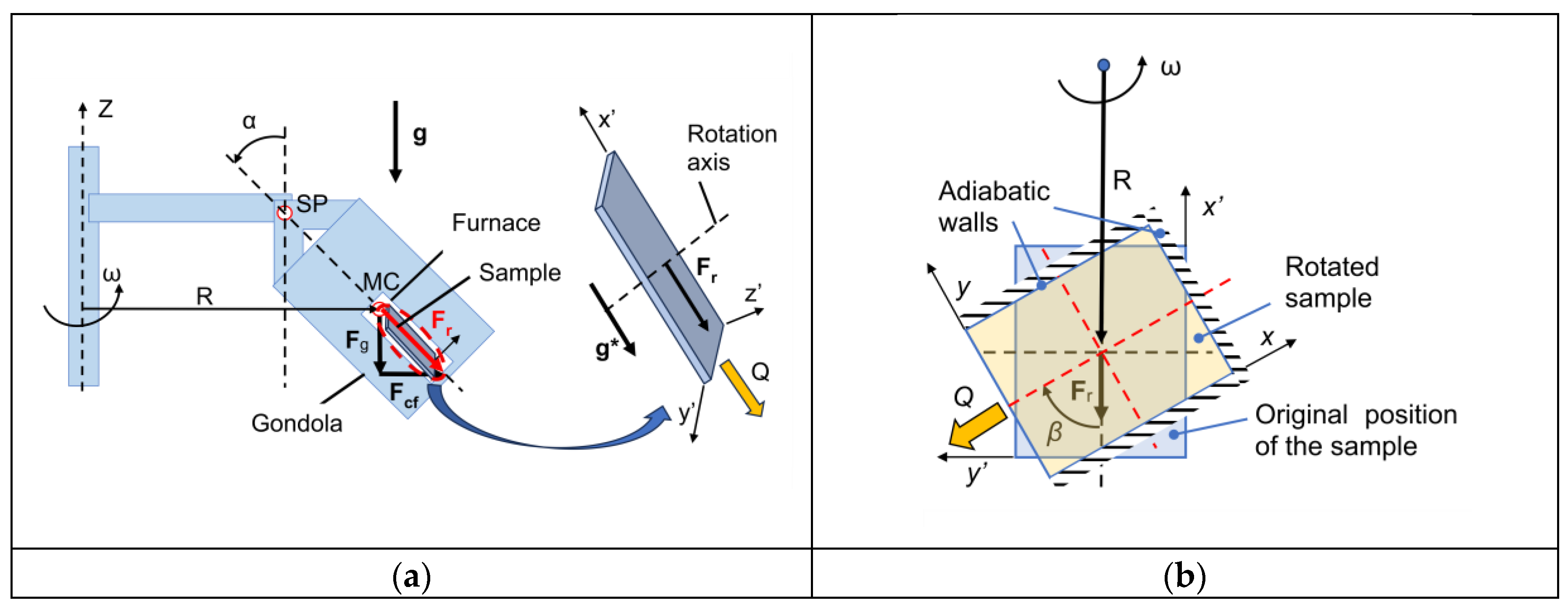
Figure 2.
The schematic of (a) the front tracking procedure on a fixed unstructured control-volume mesh [23]; (b) determination of the switching function.
Figure 2.
The schematic of (a) the front tracking procedure on a fixed unstructured control-volume mesh [23]; (b) determination of the switching function.
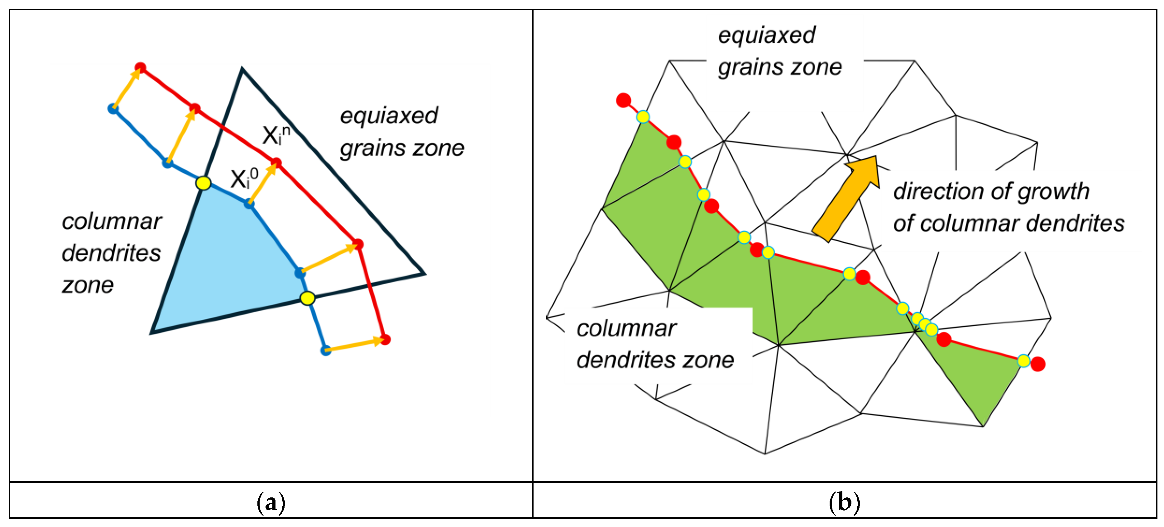
Figure 3.
Schematic of the geometry and boundary conditions of the AFRODITE benchmark casting.
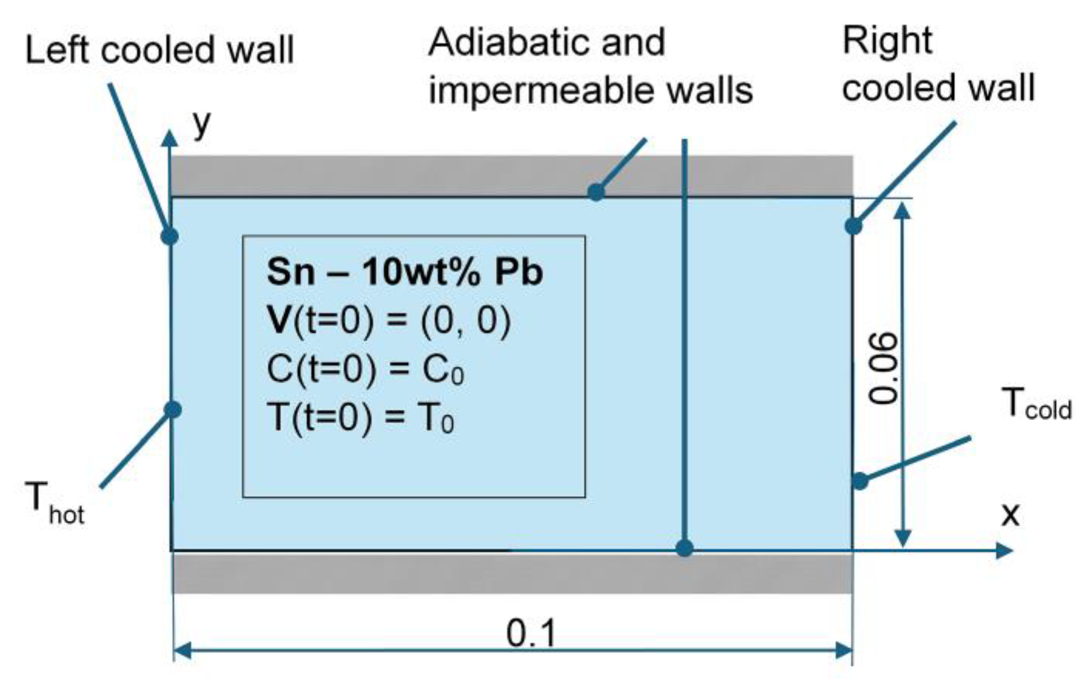
Figure 4.
Comparison of solute concentration maps predicted with EP, EP-FT, and EP-CP models, for the selected times of the mold cooling.
Figure 4.
Comparison of solute concentration maps predicted with EP, EP-FT, and EP-CP models, for the selected times of the mold cooling.
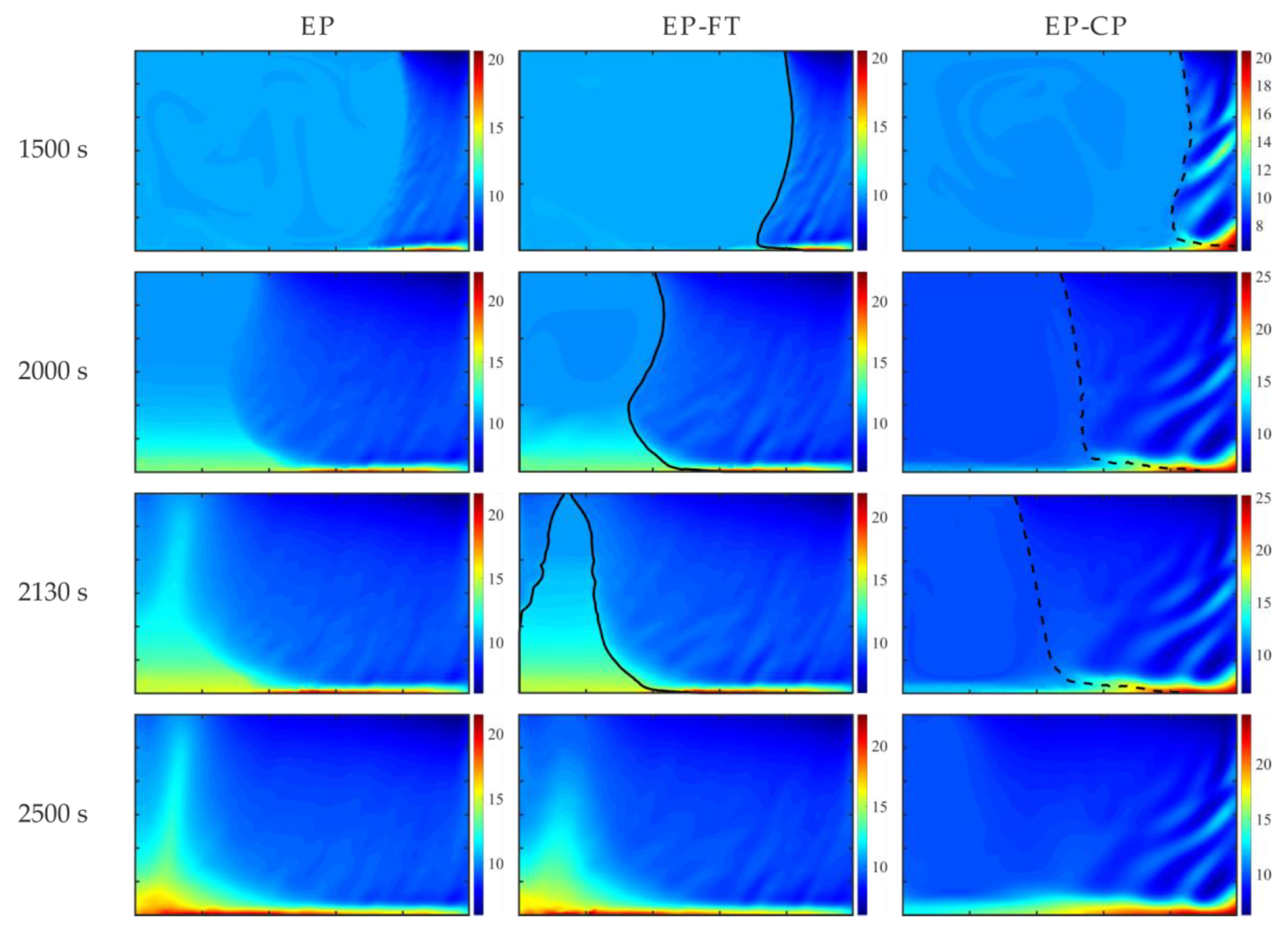
Figure 5.
Comparison of solid fraction and temperature predicted with EP, EP-FT, and EP-CP models after 2000s of the cooling process.
Figure 5.
Comparison of solid fraction and temperature predicted with EP, EP-FT, and EP-CP models after 2000s of the cooling process.
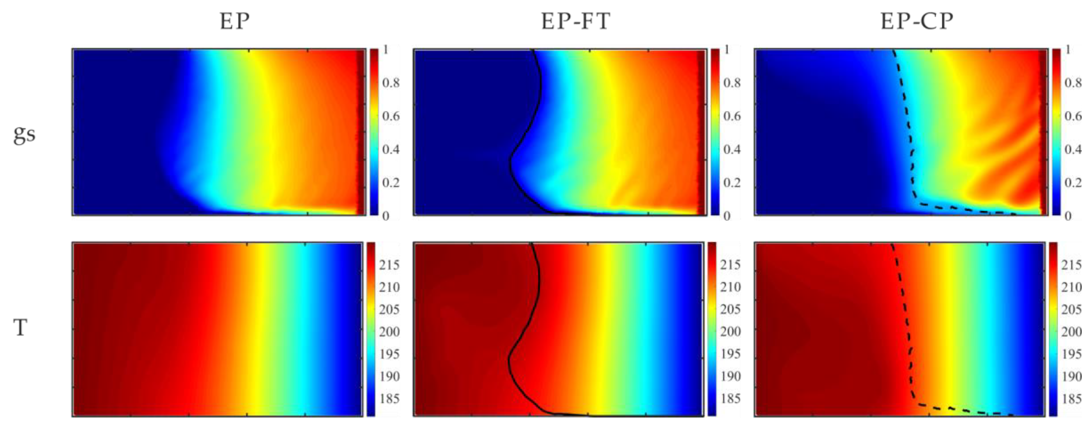
Figure 6.
Cross-sections across the domain for the completely solidified cavity, determined at various elevations: (a) 1 cm; (b) 2 cm; (c) 3 cm; (d) 4 cm; € 5 cm; predicted with the EP, EP-CP and EP-FT models and compared to experimental (Hachani et al. [44]) and numerical results (Zheng et al. [46]) results.
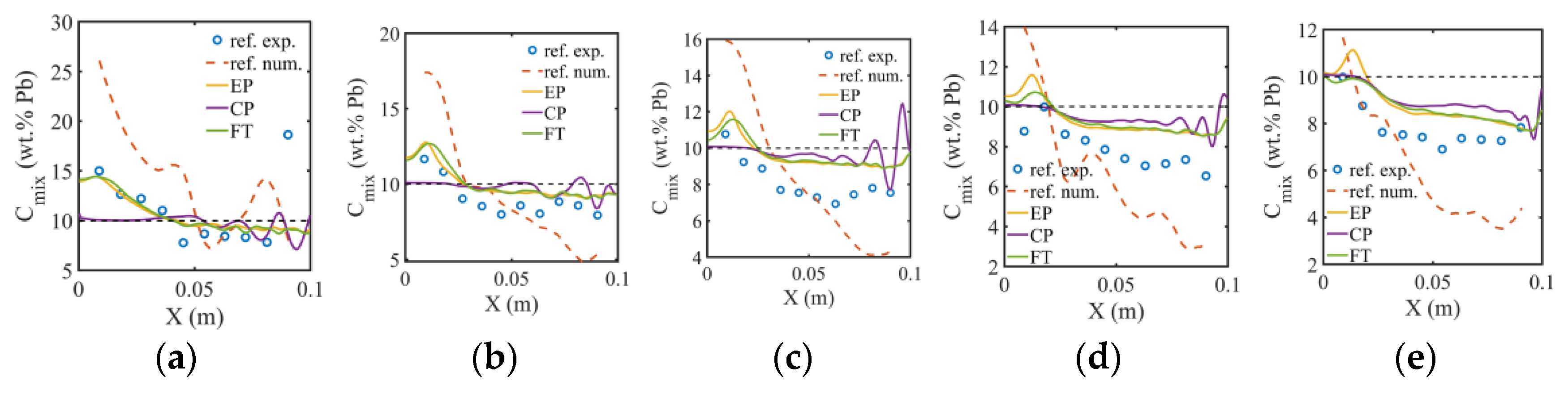
Figure 7.
Comparison of solute concentrations in the completely solidified alloy: (a) the X-radiography map of Pb concentration; (b) its digitally processed picture [44]; (c) the EP; (d) the EP-FT; I the EP-CP (gs,coh = 0.3) calculations, respectively. (a) and (b) are reprinted from publication [44], with permission from Elsevier.
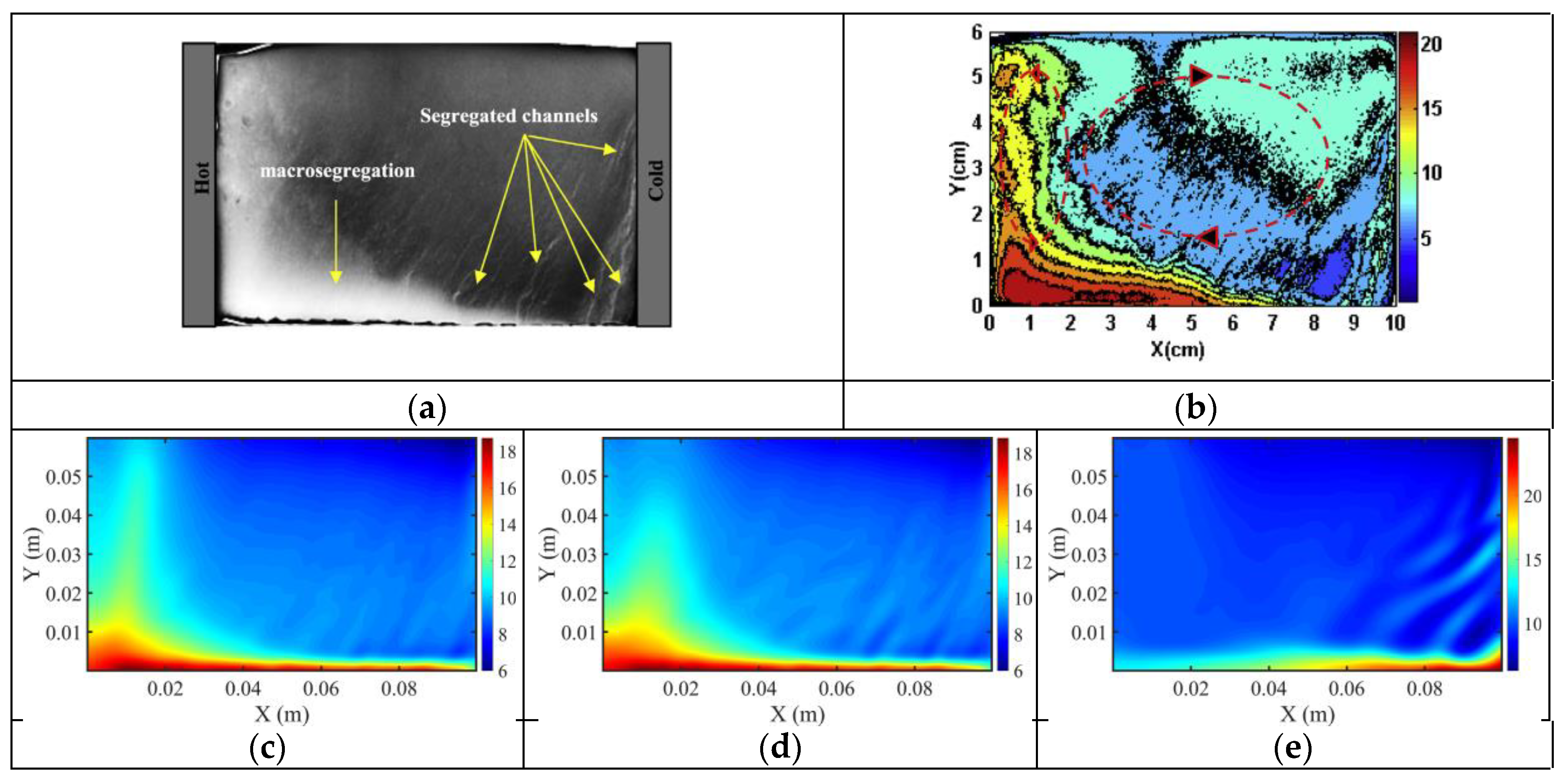
Figure 8.
Impact of the mesh density on the Sn concentration (left column) and the solid fraction (right column) after 250 s of cooling.
Figure 8.
Impact of the mesh density on the Sn concentration (left column) and the solid fraction (right column) after 250 s of cooling.
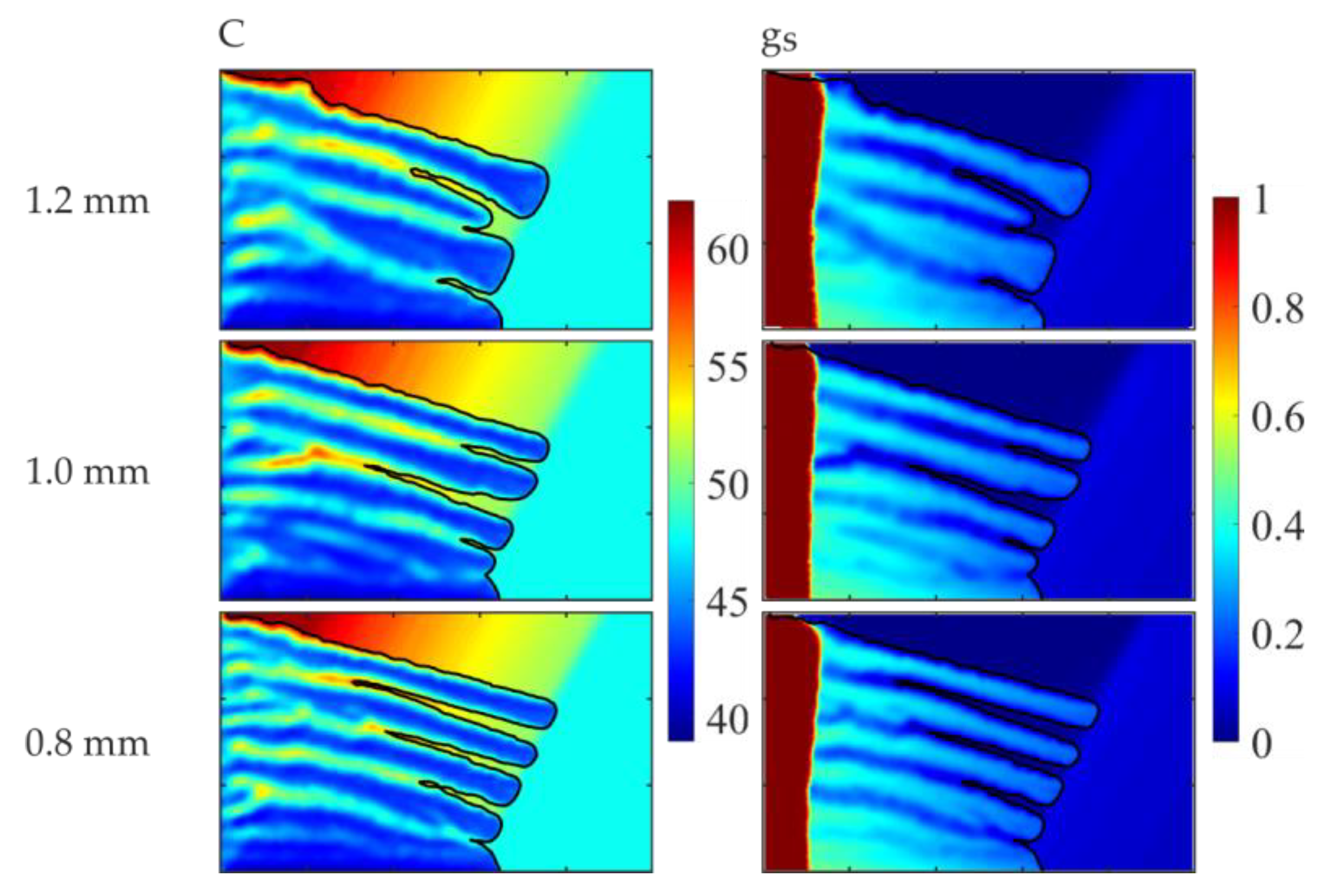
Figure 9.
Sn concentration predicted with the EP, EP-CP, and EP-FT models at the selected times of the cooling process for the effective gravity of 1g and β-angle of 90°.
Figure 9.
Sn concentration predicted with the EP, EP-CP, and EP-FT models at the selected times of the cooling process for the effective gravity of 1g and β-angle of 90°.
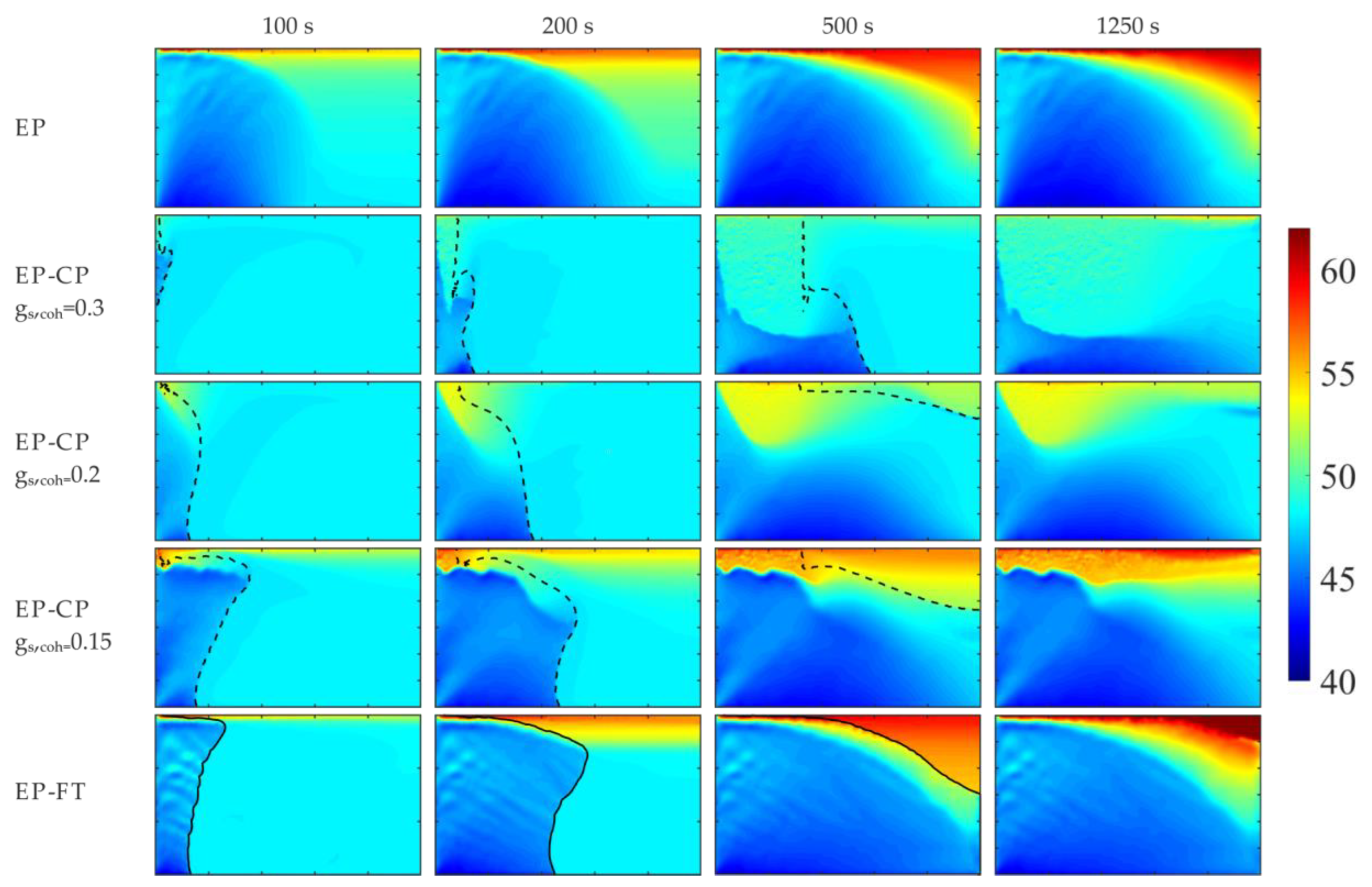
Figure 10.
Sn concentration predicted by the EP-CP and the EP-FT, at the selected early times of the cooling process, for the effective gravity of 15g and β-angle of 90°.
Figure 10.
Sn concentration predicted by the EP-CP and the EP-FT, at the selected early times of the cooling process, for the effective gravity of 15g and β-angle of 90°.
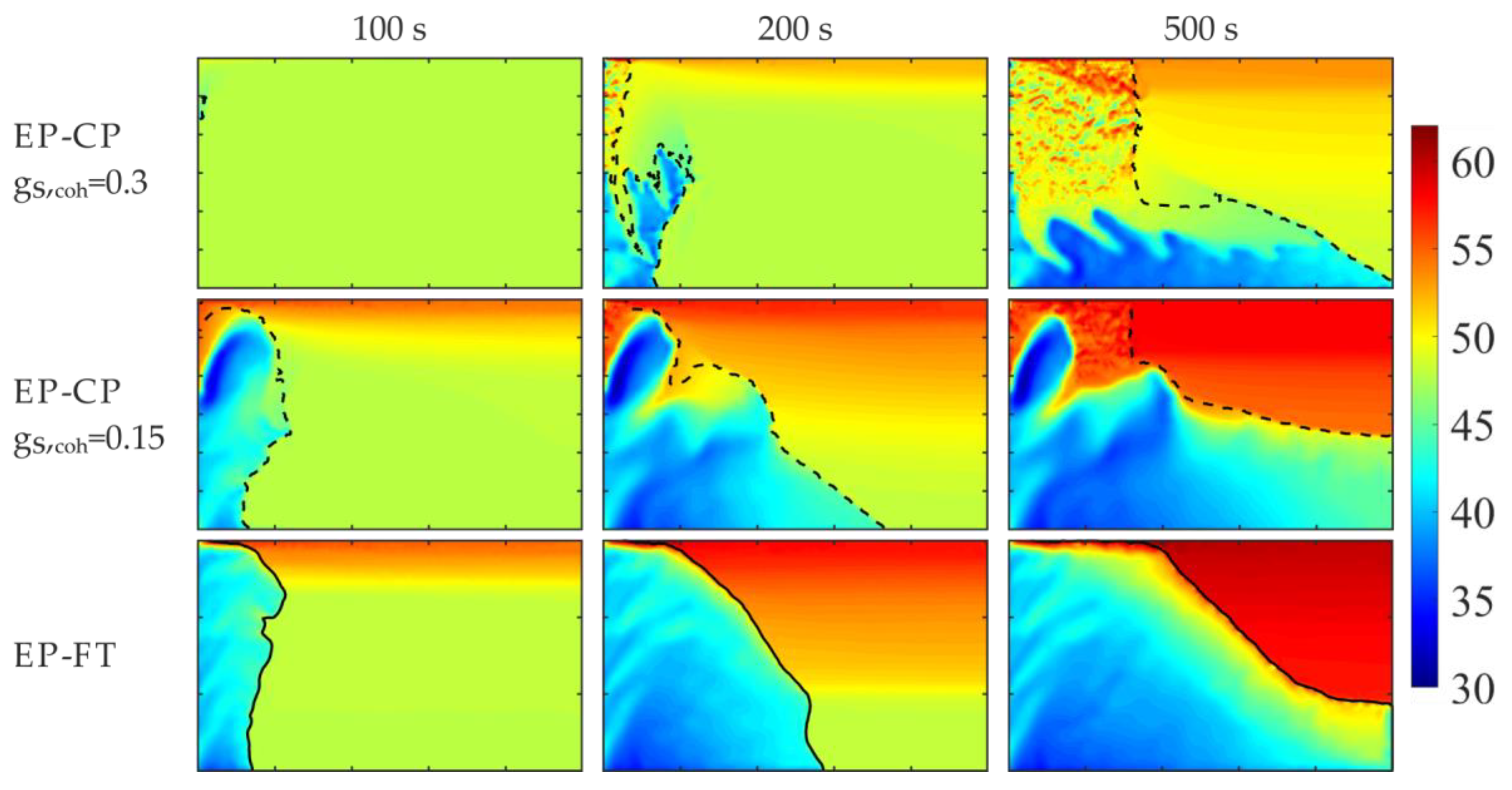
Figure 11.
Volumetric solid fraction calculated by the EP-CP and the EP-FT, at the selected early times of the cooling process, for the effective gravity of 15g and β-angle of 90°.
Figure 11.
Volumetric solid fraction calculated by the EP-CP and the EP-FT, at the selected early times of the cooling process, for the effective gravity of 15g and β-angle of 90°.
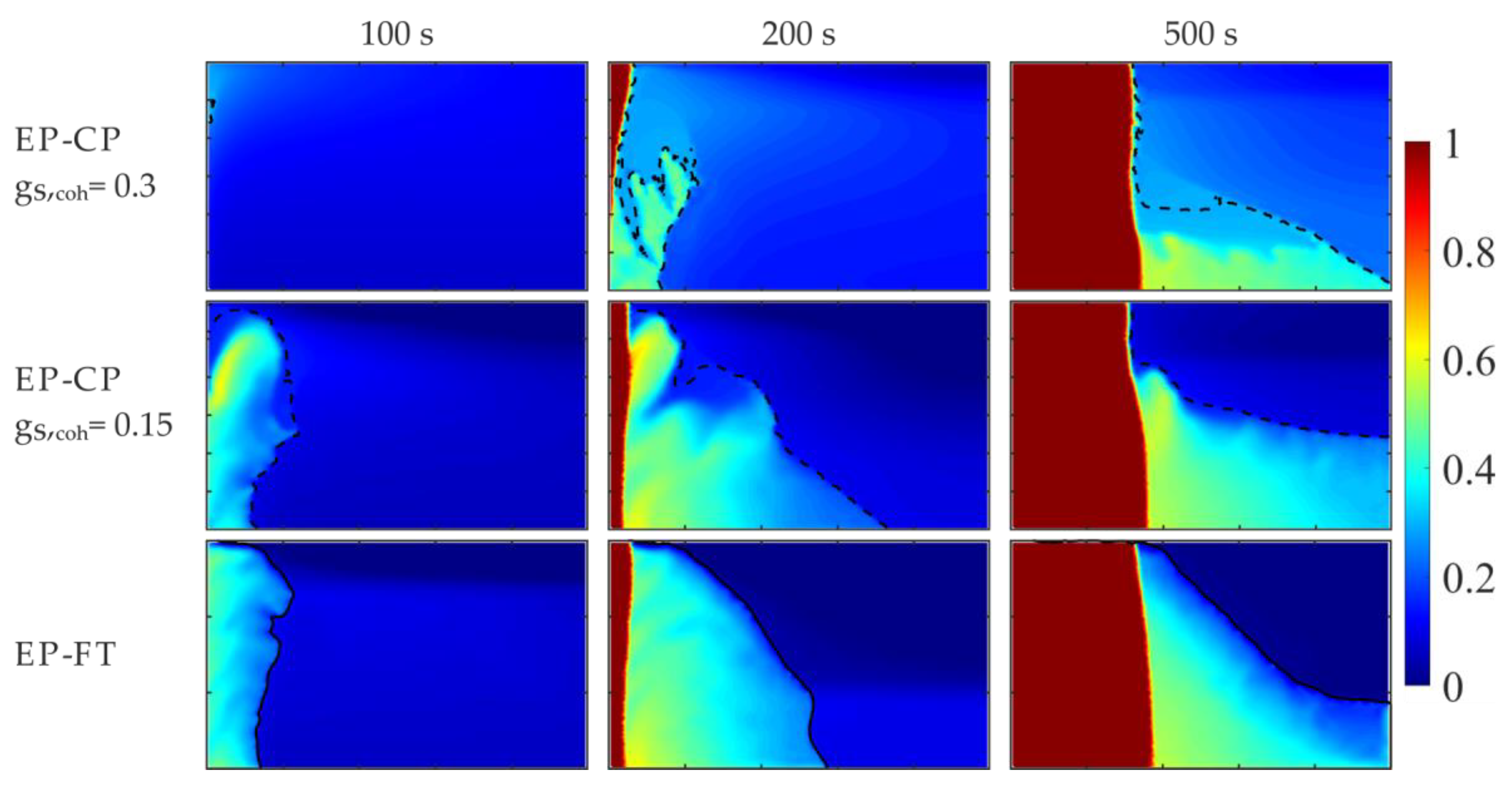
Figure 12.
Comparison of Sn concentration predicted by the EP-FT and EP-CP (gS,coh= 0.15) models, for the selected times of mold cooling, in terrestrial gravity and β-angle of 180°—the heat is extracted from the mold’s top wall.
Figure 12.
Comparison of Sn concentration predicted by the EP-FT and EP-CP (gS,coh= 0.15) models, for the selected times of mold cooling, in terrestrial gravity and β-angle of 180°—the heat is extracted from the mold’s top wall.
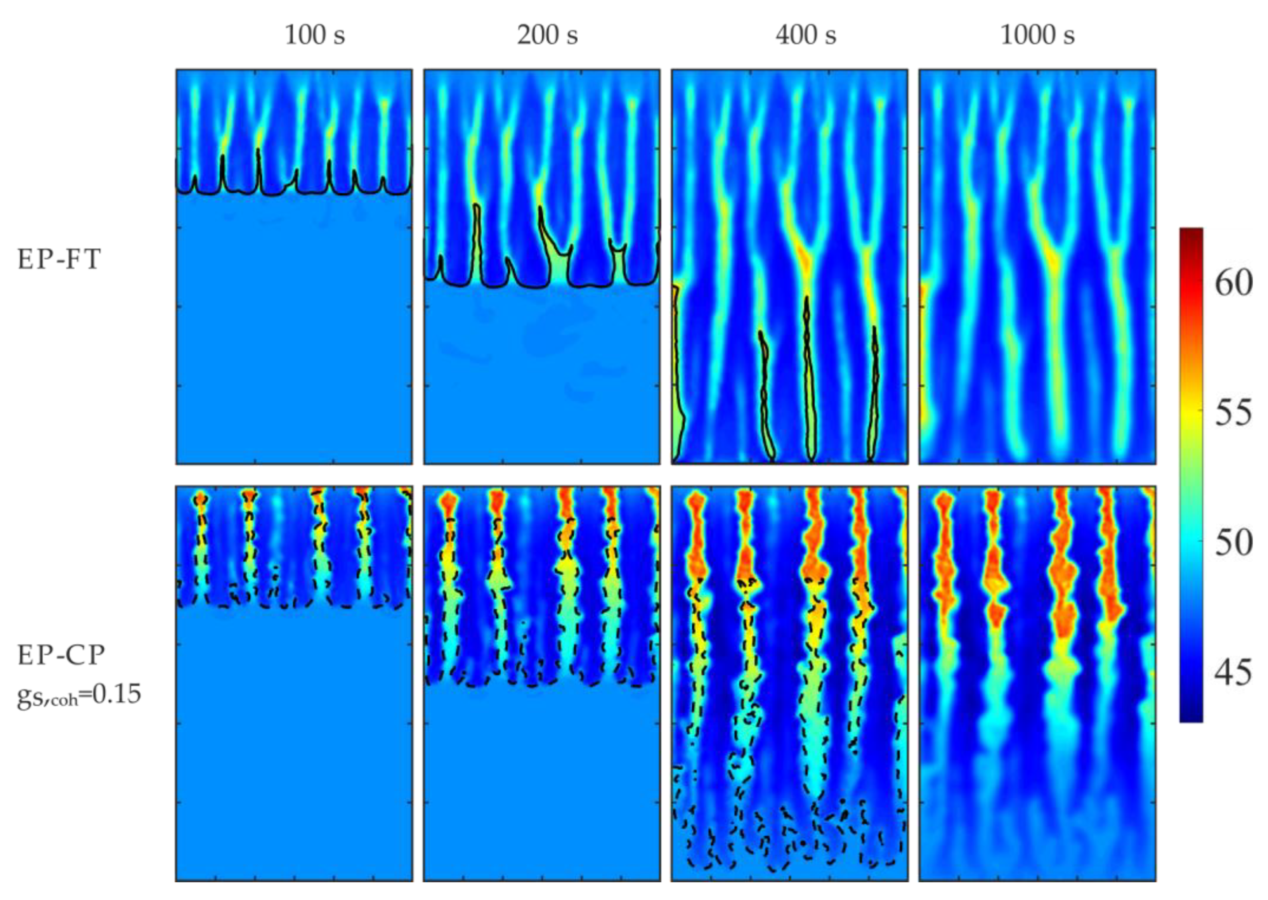
Figure 13.
Comparison of the volumetric solid fraction predicted by the EP-FT and EP-CP (gS,coh= 0.15) models, for the selected times of mold cooling, in terrestrial gravity and β-angle of 180° - the heat is extracted from the mold’s top wall.
Figure 13.
Comparison of the volumetric solid fraction predicted by the EP-FT and EP-CP (gS,coh= 0.15) models, for the selected times of mold cooling, in terrestrial gravity and β-angle of 180° - the heat is extracted from the mold’s top wall.
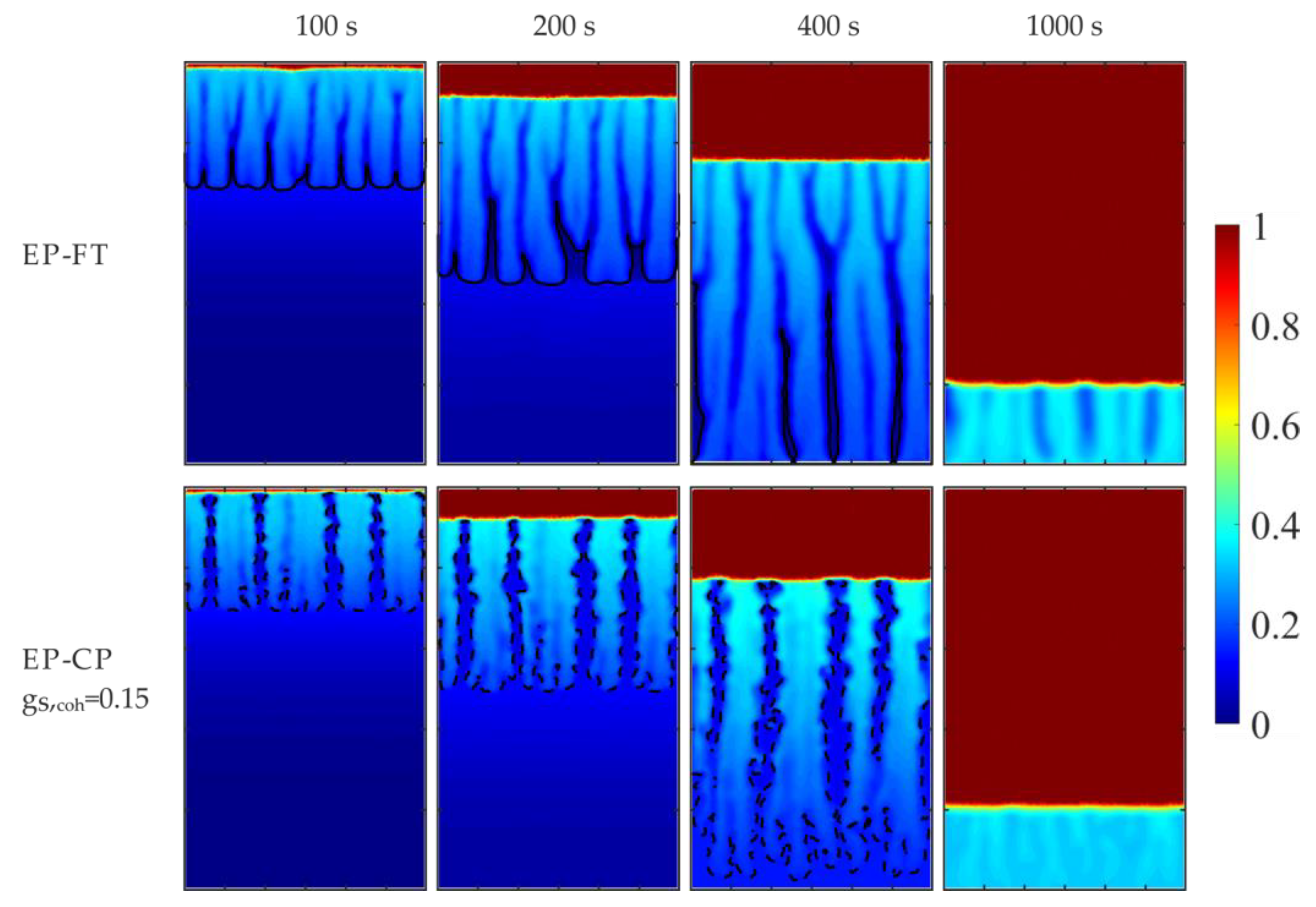
Figure 14.
Volumetric solid fraction along the columnar dendrite tips front after 250s of cooling, for various gravity acceleration levels (1g, 5g, 15g), and β-angles: (a) 90° and (b)180°.
Figure 14.
Volumetric solid fraction along the columnar dendrite tips front after 250s of cooling, for various gravity acceleration levels (1g, 5g, 15g), and β-angles: (a) 90° and (b)180°.
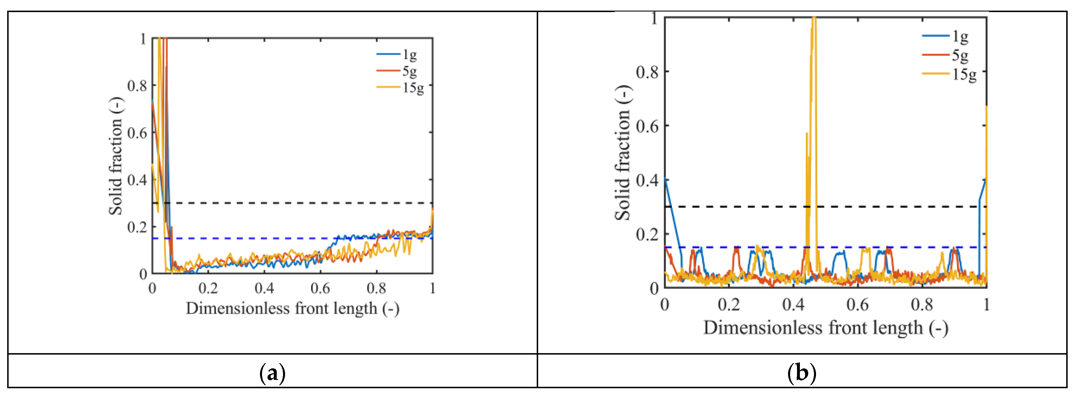
Figure 15.
EP-FT predictions of the solute (Sn) concentration after 250s of cooling for various effective gravity accelerations, g*, and rotation angles, β. The direction of heat transfer through the cooled wall is marked with the blue arrow.
Figure 15.
EP-FT predictions of the solute (Sn) concentration after 250s of cooling for various effective gravity accelerations, g*, and rotation angles, β. The direction of heat transfer through the cooled wall is marked with the blue arrow.
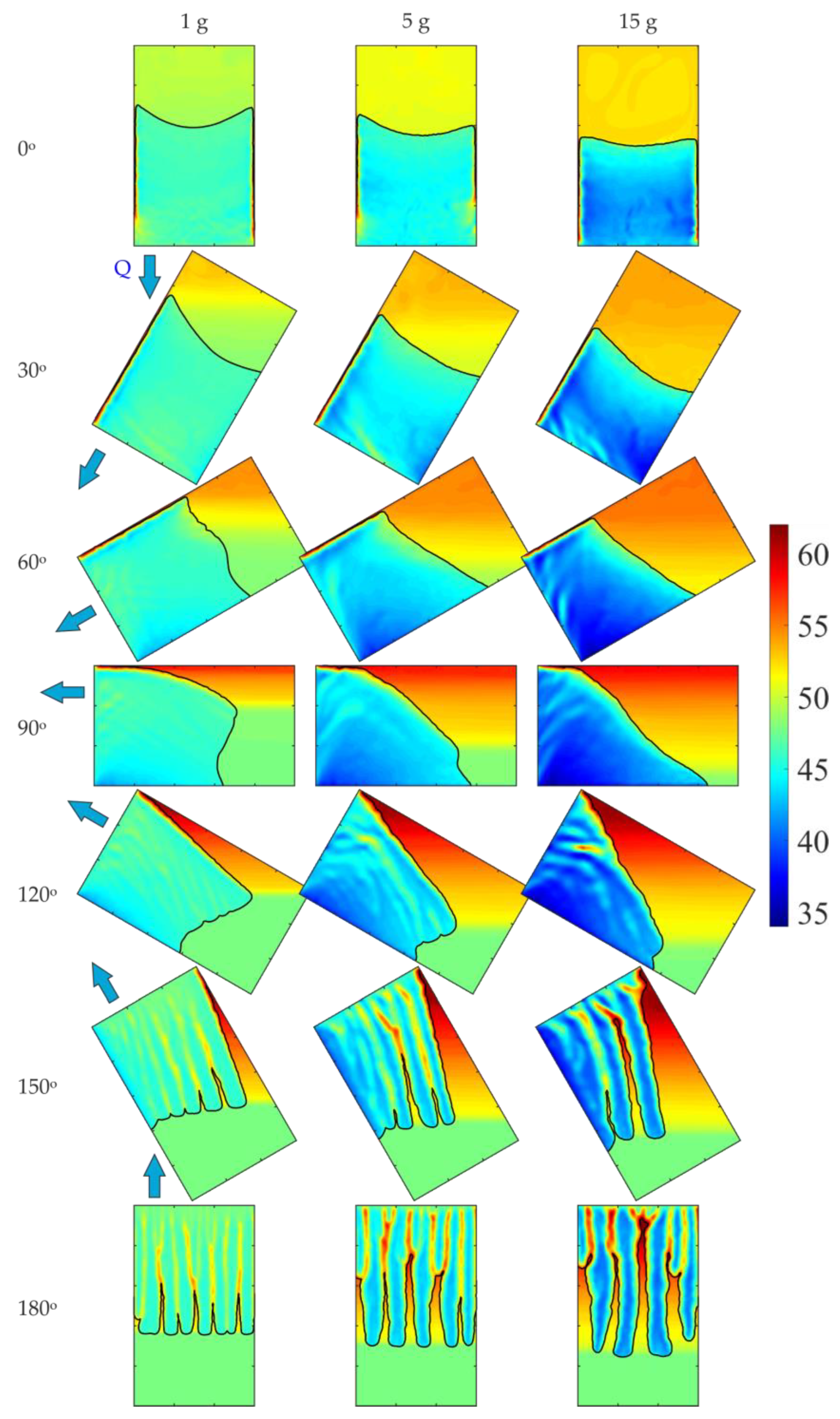

Table 1.
Material properties and boundary conditions used in calculations.
| Symbol | Units | Pb-48 wt.% Sn | Sn-10 wt.% Pb | |
|---|---|---|---|---|
| Initial mass fraction | C0 | wt%−1 | 48.0 | 10.0 |
| Density | Ρ | kg·m−3 | 9000.0 | 7000.0 |
| Specific heat | cL, cS | J·kg−1K−1 | 200.0 | 260.0 |
| Thermal conductivity | kL, kS | W·m−1K−1 | 50.0 | 55.0 |
| Viscosity | µ | kg·m−1·s−1 | 10-3 | 10-3 |
| Liquid thermal expansion coefficient | βT | K−1 | 10-4 | 6.0·10-5 |
| Liquid solutal expansion coefficient | βC | wt.%−1 | 4.5·10-3 | -5·10-3 |
| Latent heat | L | J·kg−1 | 53550 | 61000 |
| Diffusion coefficient (solid) | DS | m2·s−1 | 9·10-10 | 4.5·10-9 |
| Diffusion coefficient (liquid) | DL | m2·s−1 | 9·10-6 | 1·10-12 |
| Melting temperature of a solvent | TM | K | 600.65 | 505.15 |
| Liquidus slope | ml | K· wt.%−1 | -2.334 | -1.286 |
| Equilibrium partition coefficient | K | - | 0.307 | 0.0656 |
| Eutectic temperature | TE | K | 183.0 | 183.0 |
| Secondary dendrite arm spacing | λ2 | µm | 40.0 | 65.0 |
| Boundary conditions: | ||||
| Initial temperature | T0 | °C | 216.0 | - |
| Temperature of an ambient fluid | Tamb | °C | 25.0 | - |
| Heat transfer coefficient | h | W·m−2·K−1 | 400.0 | - |
Disclaimer/Publisher’s Note: The statements, opinions and data contained in all publications are solely those of the individual author(s) and contributor(s) and not of MDPI and/or the editor(s). MDPI and/or the editor(s) disclaim responsibility for any injury to people or property resulting from any ideas, methods, instructions or products referred to in the content. |
© 2025 by the authors. Licensee MDPI, Basel, Switzerland. This article is an open access article distributed under the terms and conditions of the Creative Commons Attribution (CC BY) license (http://creativecommons.org/licenses/by/4.0/).
Copyright: This open access article is published under a Creative Commons CC BY 4.0 license, which permit the free download, distribution, and reuse, provided that the author and preprint are cited in any reuse.


