
Submitted:
28 October 2025
Posted:
29 October 2025
You are already at the latest version
Abstract
Procedural CAD models are the primary source of detailed mechanical designs as they are editable, can convey design intent and be enriched with design and manufacturing information. However, many companies still spend significant time modifying low-quality procedural CAD models, which are often poorly structured or become unusable when geometric changes are made. Current best practices focus mainly on "how to do it well," which can frustrate users who struggle to identify the sources of errors and determine how to resolve them, leading to issues that often persist when integrating models into other applications. In contrast, we propose practices based on the principle of “how to avoid doing it wrong” derived from analyzing negative knowledge in CAD modeling.
This paper contributes to advancing the quality of 3D procedural models. Our framework adopts the three levels of quality identified in the literature: usability, re-usability, and design intent richness, while focusing specifically on deriving best prac-tices to prevent failures, based on negative knowledge related to reusability. We build on the premise that quality issues hindering reusability can be categorized into three interrelated but largely independent types, each affecting the sketches, datums, or features within a procedural model’s tree structure. In this work, we address the study of sketches. The negative impact of typical failures, identified through representative case studies that illustrate both design and redesign errors, is analyzed to extract best practices that ensure CAD model reusability.
While this study results in a practical guide for avoiding sketch-related errors that compromise the reusability of CAD models, the main contribution lies in demonstrating a framework that transforms negative knowledge into effective best practices.
Keywords:
mechanical design
; procedural CAD models
; quality CAD models
; best 3D modeling practices
; negative knowledge
1. Introduction
Contrary to popular belief, the application of 3D CAD tools in mechanical design remains an open problem. Currently, many commercial software options allow users to create primary CAD models; however, in many cases, poor modeling practices result in low-quality models that contain geometric and topological errors that hinder their reusability and obscure the original design intent [1]. Although different aspects of CAD model quality have been studied, few publications address this topic in a comprehensive manner. Many users spend considerable time trying to use or reuse low-quality CAD models, which often become unusable when changes are made to their feature-based modeling structure (model tree).
Reacting to the difficulty of editing parametric and procedural models, some companies adopt workarounds by implementing direct editing methods for local geometry modifications to meet internal deadlines. However, this approach compromises the fundamental benefits of parametric geometry, such as the automatic generation of design alternatives, design optimization, and the potential use of artificial intelligence techniques [2].
Several studies in the literature have proposed catalogs of best practices, ranging from the pioneering work of Lacourse [3], to the more recent and widely known work of Lombard [4]. Outside the academic environment, technologically advanced companies have also adopted procedures based on best practices. These practices have generally had limited public dissemination, although in some cases, they have inspired attempts to standardize such procedures and best practices, as seen in the case of the discontinued SASIG PDQ guideline and its German derivative VDA 4955 [5]. Nevertheless, there are few formal and freely available solid modeling methodologies. Bodein et al. [6] proposed an efficient modeling procedure for complex parts in constraint-based CAD tools; Gebhard et al. [7] implemented a resilient modeling strategy that prioritizes flexibility, robustness, and adaptability of the model in the face of changes and modifications; and a recent work by Company et al. [8] introduced a hierarchical, multilevel quality framework aimed at improving the usability, reusability, and semantic richness of CAD models, demonstrating its application through a manual checklist to measure CAD model quality.
Given this situation, our proposal is to organize best practices based on failure modes, prioritizing the avoidance of those failures most likely to drastically reduce the quality of CAD models. To this end, we define a framework, where—consistent with recent methodologies—the failure modes in procedural models are classified according to whether they primarily affect sketches, datums, or features. In this first work of the series, we focus on the study of negative knowledge in sketches in general, and profiles in particular. When a sketched figure—typically closed—is used for a 3D sweeping operation such as extrusion, we refer to it as a profile (thus defining profiles as the cross-sectional contours used in 3D sweep operations).
The paper is organized as follows: first, the background is presented. Next, the framework of common errors in CAD sketches is identified and linked to negative knowledge known to affect their reusability. To validate the framework, a case study was developed and analyzed by experts to derive best practices for sketching. Finally, the conclusions and lessons learned are discussed.
2. Background
According to a report by the Aberdeen Group [9], 48% of models are inflexible and fail after changes. The reusability and alterability of 3D models depend largely on modeling strategies and a thorough understanding of design intent [1,6]. Therefore, it is crucial to emphasize the importance of an efficient modeling process in achieving high-quality, error-free CAD models [10]. The financial impact of low-quality CAD models is considerable. Many companies acknowledge the problem [BRC14] and recognize that processes involving virtual models inherently contain inefficiencies, yet they reluctantly accept the associated costs.
The literature shows that various dimensions of CAD model quality have been explored. According to Contero et al. [10] the quality of CAD models can be classified into three levels: Morphologic, Syntactic, and Semantic/pragmatic, with the latter focusing on the CAD model’s ability to be reused and modified. Another study [11] identified six main dimensions of CAD quality: validity, completeness, consistency, conciseness, clarity, and the ability to convey design intent. In their work [12], Company et al. presented a new taxonomy of issues related to CAD model quality, noting that reusability involves aspects such as validity, consistency and conciseness.
Some studies frame reusability as an aspect of the broader and more ambitious objective of ensuring high-quality CAD models, emphasizing conciseness and clarity which support reusability [7,13,14,15]. However, these dimensions of CAD quality have received limited attention from industry. To improve Product Data Quality (PDQ), other studies have explored strategies introduced by engineers and technical graphics educators to enhance CAD education [16,17,18,19]. Despite these efforts, there remains a scarcity of publications that address the subject comprehensively and holistically. For the purposes of this work, we adopt the framework proposed by Company et al. [8], which evaluates CAD model quality across three levels: (1) usability, (2) reusability, and (3) semantic richness. (1) A usable model is defined as one that maintains validity and completeness, remaining free from errors that compromise these aspects. (2) Reusable models exhibit consistency and conciseness, without errors that hinder their reuse. (3) Lastly, semantically rich models are clear and effectively communicate design intent, conveying relevant information to stakeholders who interact with them.
In parallel with CAD quality studies, González et al. [12] presented a taxonomy of issues related to CAD model quality in explicit (declarative or evaluated) and procedural (generative or history-based) types. The taxonomy identifies morphological issues (related to geometric and topological accuracy), syntactic issues (which assess the proper use of modeling conventions), and semantic errors (which focus on the ability to modify and reuse CAD models). The study concluded that there is no general agreement on the procedure for dealing with errors in CAD models. Additionally, commercial Model Quality Testing (MQT) tools only provide mechanisms to identify geometrical and topological errors as described by standards such as VDA 4955 and SASIG PQD 2.1, but they do not consider aspects related to verifying and effectively implementing design intent, nor do they measure the capability of 3D models to be reused and modified [12].
In the public domain, there are few formal modeling methodologies available, primarily focused on solid modeling. Examples include patent-protected horizontal modeling [20], resilient modeling [7] (accessible for a fee), and explicit reference-based modeling [6,21]. Other approaches are embedded in extensive learning manuals for specific CAD applications, making them difficult to extract and apply widely in a meaningful way. However, all these advances have largely remained isolated due to a lack of continuity, possibly because of the absence of a more general framework for collecting and classifying best practices.
Despite the widespread use of current procedural 3D CAD modeling software, which facilitates detailed mechanical design, many CAD instructors still prioritize command-based learning over strategic knowledge. This approach often leads designers to produce low-quality models, neglecting the strategic knowledge necessary for creating models that are editable and reusable in the future [11,21]. Command knowledge tends to focus solely on the tools available within CAD software. Strategic knowledge, unlike command knowledge, explores alternative methods for accomplishing specific tasks and the decision-making process involved [22]. Thus, learning tends to focus on the dissemination and development of procedural knowledge and skills, emphasizing knowing “that” or knowing “what” related to the operation of CAD systems, but not on how to avoid serious mistakes or negative knowledge, which is a key aspect of professional expertise. In other words, many instructors continue to prioritize learning based on command over the more desirable approach of strategic knowledge.
Moreover, in cases where strategic knowledge prevails, the focus is often on how to do things well, while avoiding doing them wrong receives little or no attention. This is an important capability that has been overlooked both in research and teaching: knowing what to do in each situation during the modeling process to obtain a quality model, that is, knowing what not to do in any situation to avoid mistakes, representing a kind of negative component within strategic knowledge. Although some studies in the literature have mentioned this negative knowledge in the field of artificial intelligence [23,24], in education [25] and in knowledge management [26], it was not until Mandorli & Otto [27] that a first approach to a technique with negative knowledge on CAD modeling was presented. This approach is inherently consistent with, and different from, traditional approaches based on positive knowledge. The work by Mandorli & Otto [27] represents a novelty in the field of parametric CAD, given the absence of catalogs or reference lists containing entries of errors and mistakes along with descriptions of how they occurred or how they could have been avoided, while focusing the work on basic feature deficiencies.
3. Error-Based Negative Knowledge in CAD Models
We have developed a framework that can significantly improve the reusability of CAD models by classifying best practices according to how they contribute to help resolve errors that arise during modeling or editing. Our aim is to shift the perspective from merely fixing errors to understanding how to proceed when errors occur, thereby transforming these experiences into practices that prevent recurrence. To our knowledge, no studies have proposed best practices based on the daily experience of designers facing the dilemma of being unable to reuse their models.
We start from the general hypothesis that common errors in 3D CAD models affect their reusability to varying degrees. To validate this hypothesis, we establish a framework to assess the reusability of sketches, datums, and features. All three geometric items are known and precisely defined. We refer to sketches and features using the terminology of ISO/DIS 24351:2025, which calls them sketch features and modeling features, respectively. It is worth noting that in what follows, sketches and profiles are considered synonymous: sketches are generally 2D parametric drawings, and profiles are the specific parametric drawings used to sweep 3D features. Datums are the reference elements described as situation features in the ISO 5459:2024 standard. A common erroneous practice is to treat sketches and datums as subsidiaries of features, as is typically done. In contrast, the novelty of our proposal lies in analyzing the quality of each of these items independently, without considering any of them as subordinate to the others.
The second novelty is to derive good practices from bad practices, obtained by contrasting desired quality criteria with commonly observed errors. The framework is developed by combining the quality dimensions developed by Company et al. [11], further grouped into three quality levels [8], with the error classification proposed by Gonzalez et al. [12], who distinguished morphological, syntactic and semantic errors. We agree with Gonzalez et al. that “The morphological level is not critical in procedural models, as it is automatically tested by most CAD applications.” However, they highlighted issues with “ambiguously defined datums – mainly those defined implicitly”, and “seemingly well-constrained profiles (that) may sometimes be compatible with different geometric or topological solutions, which are not necessarily compatible with design intent.” Syntactic errors are only marginally considered here, as they generally arise from mapping failures and inconsistencies, mainly related to interoperability. Finally, semantic errors are partly considered. They are primarily associated with the third level of quality (semantic richness), although unclear model trees or missing design intent clearly influence the reusability of models.
Table 1 summarizes our reinterpretation of these errors. Flags in the last column indicate whether the errors primarily affect sketches (S), datums (D), or Procedural Model Tree structure (PMT), in which features are arranged to generate a model.
Table 2 summarizes our view of the potential negative consequences of errors that typically occur in a model. In this work, they are limited to sketches (S). For example, we focus on under-constraining because it is a common modeling error that can lead to unpredictable behavior, potentially forcing the model to be rebuilt before it can be reused.
In this classification, we distinguish between topology and geometry. Topological changes involve adding or removing lines in a profile, while geometric changes modify the shape or size of one or more profile elements. A global geometric change produces figures homothetic to the original ones (such as equidistant transformations), whereas local geometric changes typically result in figures that are significantly distorted relative to the original. Shape changes when part of the figure undergoes such drastic deformation that it can no longer be clearly identified as similar to the original. This includes distortions such as extreme elongation or collapse of a part. Size or dimension changes occur when the altered figure remains recognizable as the same shape, while some local regions vary in size or shift position.
The prevalent errors summarized in Table 2 guided the design of case studies aimed at determining their influence on model reusability. The three main characteristics of the case study testing framework are as follows:
- Instead of using very simple examples to test the effect of each possible error in isolation, we chose to examine the impact of different errors on somewhat more complex models. The rationale is that, while very simple examples allow us to isolate the effect of individual failures, they are highly unrealistic case studies, since designers rarely make mistakes in very simple models. González-Luch and Plumed [28] identified several quality errors that frequently occur during model creation, particularly impacting models of average or high complexity. To uncouple the effects of potentially combined errors, we repeated redesigns in different orders to gain insight into the individual effect of each error.
- We attempt to validate hypotheses developed from our experience as instructors of industrial designers. Our insights come not only from training engineers for over 15 years, but also from consulting the help system of a representative CAD software [29]. It was not a surprise that, like many others, this help system focuses on command usage rather than work strategies, offering little to no documented guidance on problem-solving or error prevention. Beyond validating our hypotheses, we explored its implicit negative knowledge and its corresponding negative consequences related to common deficiencies in CAD model usability and reusability.
- The hierarchical arrangement of columns in Table 2 shows that a single error can generate multiple negative knowledge hypotheses. In the case study, it will become clearer that negative knowledge can extend to increasingly specific cases, giving rise to practical rules that can be arranged "in cascade," with very specific rules for highly specific cases at the lower levels, and generally recommendable rules at higher levels.
4. Negative Knowledge from Sketches
Here, we first explain the design of the case study and then describe the analyses performed to validate the hypotheses from Table 2 and to derive good practices from negative knowledge.
4.1. Case study
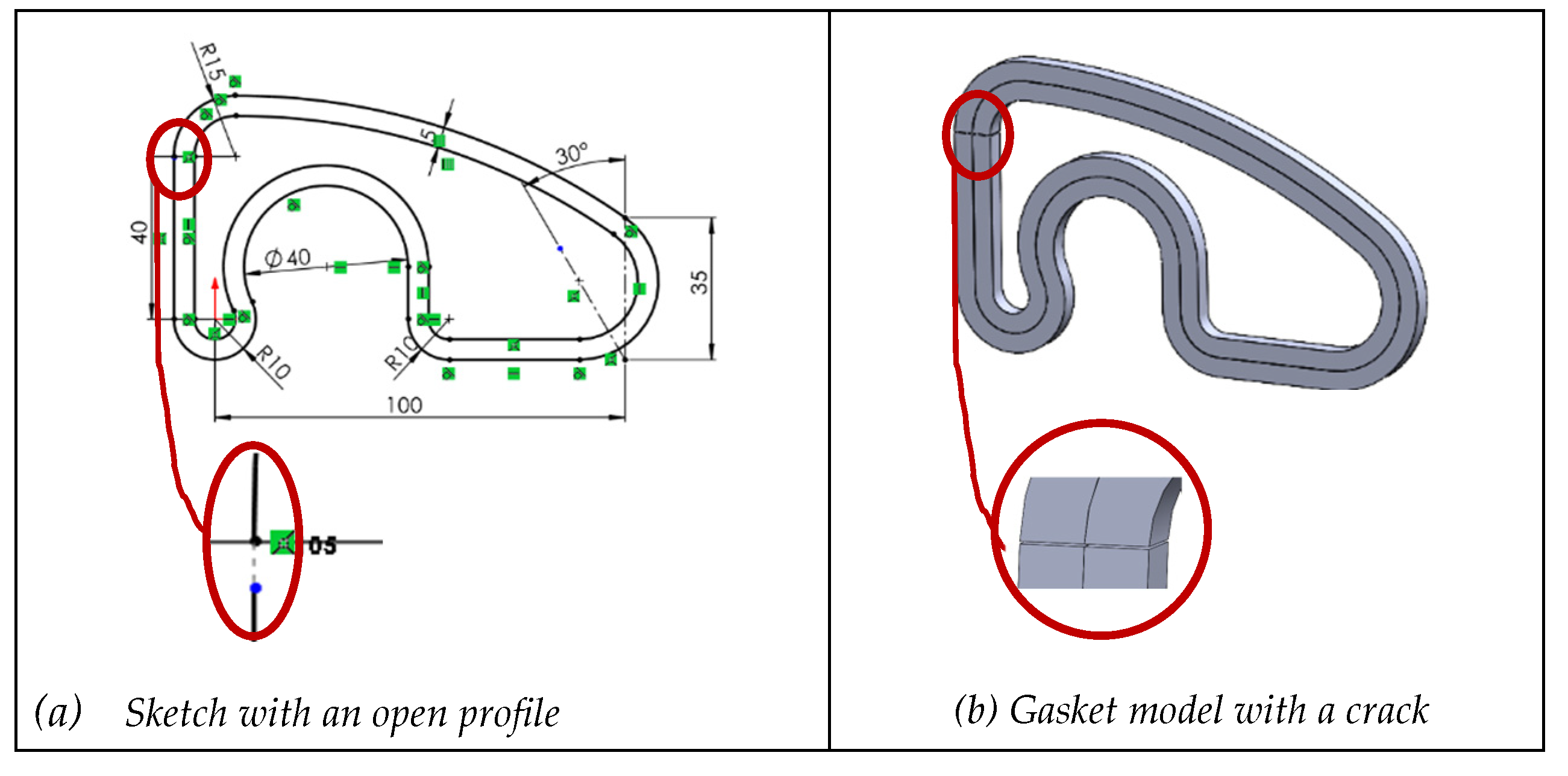
A training sketch of moderate complexity was selected from the book by Company and González. [30] (Figure 1a), from which a parametric and variational sketch was created with SolidWorks© (Figure 1b). Note that SolidWorks© automatically adds fusions (C0 connectivity) between the endpoints of consecutive lines or arcs, which the user cannot display or remove as they can with other constraints. This behavior proves to be significant in the procedures for repairing redesigns.
Two typical redesign changes were made by sequentially increasing the height by 25% (dimension 40 changed to 50) and the width by 50% (dimension 100 changed to 150), simulating modifications to the main dimensions of the part, such as scaling or resizing, to adapt it to a new component or function. These unequal percentages are common in design modifications and are large enough to typically produce a global impact, as sketches often cannot maintain their geometry and topology, or may generate unexpected behavior, negatively affecting the design. The changes were also applied twice in reverse order.
Finally, we attempted to reverse the faulty edited sketches by manipulating their free-moving elements. This manual adjustment illustrates the varying levels of difficulty in making edited sketches reusable. Sometimes the edits succeed, but more often they result in even more complex geometric shapes.
4.2. Negative Knowledge Simulations
Imperfections related to the negative knowledge listed in Table 2 are artificially introduced by altering constraints or geometrical elements. These imperfections are introduced either in isolation or by type, to study their specific impact on reusability. As a result of the effort to isolate the effects of different failures, three scenarios (with some sub-scenarios) were recreated:
- Case 1. Failure in constraining sketches by overlooking dimensional (continuous) and/or geometric (discrete) constraints. In this case, we demonstrate how the framework can be extended “in cascade,” by studying different sub-cases of poorly constrained profiles selected based on our experience: (1) leaving the entire profile unconstrained, (2) removing only geometric constraints, (3) removing only dimensional constraints, and (4) removing just some constraints, which may be dimensional, geometric, or some critical.
- Case 2. Artificially simulating how excessive overconstraining limits sketch editability.
- Case 3. Replicating sketches with inconsistent geometry to analyze their reusability.
We next break down the first case into five subcases to demonstrate the characteristics of the expert-based case selection and analysis method. The results obtainable through the framework are extensive and exceed the scope of this paper. Since the goal of this work is to demonstrate the validity of the framework and provide a comprehensive view, we summarize the remaining cases for brevity. Upon request, interested readers can access a technical report containing all details of the design and analysis of the cases we have studied.
4.2.1. Case 1.1: Fully Unconstrained Profile
According to H1 from Table 2, non-constraining leads to non-reusable profiles due to unpredictable alterations during editing. After artificially removing all constraints from the gasket profile, Figure 2 illustrates the results of both redesign sequences, as well as the subsequent failures encountered while attempting to correct the resulting incorrect shapes.
This case shows that missing dimensional and geometric constraints on a sketch significantly impact its reusability (while they may have little impact on strict usability, where “strict” means that the sketch is never edited). The absence of these constraints results in multiple unfixed degrees of freedom in the geometric elements, allowing unpredictable changes, such as unexpected deformations when modifying dimensions. Additionally, the sequence in which these changes are applied can unintentionally alter the shape and size of the sketch. Without a structured constraint system, restoring the sketch to its original state becomes complex and may introduce further discrepancies, directly compromising its reuse.
We note that an advanced user could anticipate and manage this seemingly chaotic behavior of the geometric solver, understanding that the solver prioritizes certain constraints or moves unconstrained elements in specific ways to adapt the shape to changes in neighboring elements. Moreover, experienced users are skilled at handling polylines chained by fusions, which are cryptic for novice users. However, here we focus on analyzing the interactions and misunderstandings that occur between a basic or average user and the CAD application.
Based on the analysis of the case study, we present the following negative knowledge resulting from simultaneously missing dimensional and geometric constraints on sketches:
- Unconstrained sketches (commonly found in imported models with reconstructed features) may be usable as-is, but they are rarely reusable when modifications are needed.
- Experienced users may manage to repair distortions that arise when editing an unconstrained sketch, but doing so requires a combination of time, skill, and luck.
- Hidden constraints, such as fusions connecting the endpoints of polylines, lead to even more unpredictable sketch behavior during editing than the total absence of constraints.
In CAD and computational geometry, a polyline is a sequence of connected lines (typically straight segments and circular arcs) that form a single object. Polylines are useful in CAD as they efficiently convey profiles and are easier to edit than separate lines. Those geometrical entities are called chain of connected lines in SolidWorks©, and polylines in AutoCAD. Their properties and editing tools can vary significantly between CAD systems.
For example, in SolidWorks©, when creating such a chain, the lines remain independent elements (lines, arcs), but the connection points between elements are fused. This fusion internal and does not appear as a constraint that the user can add or remove. The software does allow segments to be separated by dragging, but only through the “Detach Segment on Drag” function. This internal fusion of endpoints reduces degrees of freedom by preventing disaggregation of the elements.
The lessons learned from the above negative knowledge are:
- Always constrain sketches or at least constrain them before reusing them (even if the constraints added by an automatic algorithm are not optimal).
- Avoid editing individual components of polylines separately. Instead, treat the polyline as a whole and start by fixing its simpler, more independent components, which helps reduce their tendency towards chaotic behavior. CAD applications that support polylines often allow users to manage each line separately, but they rarely provide simple ways to “break” the polyline using easily editable constraints. Typically, separating the endpoints of consecutive lines requires specific editing operations.
4.2.2. Case 1.2: Dimensionally Unconstrained Profile
To simulate H2 from Table 2, we artificially removed all dimensional constraints. The editing sequence was irrelevant, as unexpected geometry appeared in both cases. Not surprisingly, the deformations affected the sizes, not the topology.
In an attempt to repair the distorted sketches and restore their original shapes, some lines of the polyline as well as a fusion at a joint point were manually edited. These local changes required in the distorted areas typically need compensation for new distortions that may arise elsewhere. The behavior differed depending on whether manually editing the polyline or the joint point:
- Moving the lower-strength segment resulted in a new deformed sketch affecting its size (Figure 3b,e). In both cases, a local shrinkage appeared, as if the sketch had been stretched.
- Moving a joint point on the lower segment resulted in a new deformed sketch affecting its size (Figure 3c,f). Local swelling appeared, while other parts seemed stretched.
- The sequence of restoration did not affect the final geometry.
Restoring the original shape is not fully feasible. However, the deformations were more localized than before, with some areas showing local swelling and others stretching.
Based on the analysis of the case, we present the following negative knowledge from missing dimensional constraints on sketches:
- Although this is a common mistake, since many sketch editors automatically add most geometric constraints but do not usually add dimensional constraints by default, relying solely on geometric constraints results in unpredictable sketch behavior when edited.
- When a sketch lacks dimensional constraints, it may still be reusable, but rescaling (inflates/deflates) occurs unpredictably during editing. This makes the sketch unreliable for reuse, as it limits the ability to maintain desired proportions and causes size deformations
- Attempting to manually repair unequal inflations requires trial and error, with no guarantee of restoring the original dimensions, increasing effort during redesign.
The lessons learned derived from the above negative knowledge are:
- Individual dimensional constraints control local size, while their joint application governs overall rescaling.
- When sketch rescaling leads to irregular or unexpected inflation/deflation, the dimensional constraints and their interrelations must be reviewed.
- When a poorly constrained sketch inflates or deflates locally during editing, size constraints are often missing in the affected area.
4.2.3. Case 1.3: Geometrically Unconstrained Profile
To simulate H3 from Table 2, we artificially removed all geometric constraints. The objective is to show the impact on sketch reusability when sketches have only dimensional constraints, and to evaluate the extent to which geometric constraints can be eliminated or modified without compromising reusability.
In the particular example of the gasket, equidistance plays a complex role in controlling the geometry of the entire profile, as it combines a geometric constraint plus a dimensional one. Removing equidistance automatically removes the associated separation dimension as well.
We therefore simulated two subcases. In the first subcase, only the separation distance between C6 and its equidistant arc (as labeled in Figure 1a) was reintroduced, simulating the event of noticing that removing the offset had unexpectedly erased a dimension and restoring it. In the second subcase, all dimensions were fully reintroduced (equidistance between L1 and its inner parallel line, equidistance between C2 and its concentric inner circle, etc.), simulating a scenario where geometry is unconstrained but all dimensions are fully constrained.
This approach not only resolves the complexity introduced by the equidistance, which could mask the verification of hypothesis H3, but also indirectly verifies hypothesis H4.
While Figure 4 shows that unexpected geometry (highly altered shape and size) appeared in both redesign sequences, the failures differed: the height-width sequence mostly affected topology, while in the width- height sequence mainly altered shape and dimensions.
In an attempt to repair the distorted sketch and restore its original shape, some lines of the polyline (specifically the lower segment L3) were manually adjusted. The observed results were as follows:
- The inner contour remained unchanged when editing the outer contour, since most of the links between them had been removed. In other words, when the exterior profile is not geometrically constrained or connected to the interior, it is more susceptible to distortion during editing.
- Both sequences resulted in uncontrolled deformation (Figure 4b,d), producing twists in the sketch.
- The order of restoration affected the final geometry.
- The topology was mostly affected in the height-width sequence, while shape and size were primarily altered in the reverse (width-height) sequence.
In the second subcase, the equidistance relation was removed only after the thickness dimension had been added to all the pairs of equidistant lines. In both redesign sequences, significant local alterations appeared (Figures 5a and 8c). Attempts to repair the distorted sketch and revert to its original shape resulted in:
- Uncontrolled deformations in both sequences (Figure 5b,d).
- The order of restoration tasks affecting the final geometry.
- Topology being somewhat affected in the height-width sequence, while geometry (shape and size) was primarily affected in the reverse (width-height) sequence.
The impact on geometry and topology of the sketch was more pronounced when the equidistant constraint was maintained only for part of the sketch, compared to when it was applied to all equidistant entities. Therefore, the thickness constraint appears to help mitigate these effects, as the twisting observed after editing and during attempts to revert faulty changes was more localized.
From this case, the following negative knowledge can be derived:
- Dimensional constraints alone are insufficient to prevent unexpected deformations during sketch editing.
- Removing complex geometric constraints, such as equidistance, critically affects certain types of geometric figures and often results in non-reusable sketches.
The corresponding lessons learned are:
- Editing sketches with missing dimensions can easily produce local distortions.
- Manually editing sketches with missing dimensions rarely causes swelling or shrinking but often introduces local twists.
- Equidistance constraints strongly link otherwise unconnected profiles, enhancing robustness against undesired changes. However, they also make editing more difficult, so temporarily removing them while editing the original profile may be advantageous.
4.2.4. Case 1.4: Partly Incomplete Dimensional Constraints
To simulate H5 from Table 2, we artificially removed selected geometric constraints, specifically the tangency constraints between consecutive arcs. The results show that the order of dimensional changes had a minor impact, as unexpected geometry emerged mostly affecting both shape and dimensions in the height-width sequence (Figure 6a), while topology was mostly affected in the reverse width-height sequence (Figure 6d).
After returning the base lower lines to their original positions, the resulting sketches (1 and 2) exhibited new deformations affecting shape and size (Figure 6b,e). Subsequent dimensional changes, restoring the 25% length increase and 50% width increase to their original values, revealed that topology was affected in the width-height sequence, whereas dimensions were primarily affected in the reverse sequence (Figure 6c,f).
This case demonstrated that removing tangent constraints on a sketch has a smaller impact on topology compared to cases where geometric constraints are entirely absent, although it still compromises reusability by preserving continuity. The editing sequence makes a difference. When height was changed first, followed by attempts to revert to the original, the sketch’s dimensions and shape were affected. However, when width was changed first, both the initial change and the restoration attempts primarily affected topology.
Based on the analysis, the following negative knowledge can be derived:
- The absence of tangency constraints between arcs results in first order (C⁰) discontinuities, preventing smooth curve transitions and compromising both form and model regeneration.
- Loss of tangency leads to abrupt shape changes during dimensional adjustments, even with minimal edits, due to unstable directional continuity at junctions.
- Dimensional constraints alone cannot adequately replace tangency constraints when smooth curves or parametric consistency are required.
The lessons learned are:
- To ensure the reusability of sketches with curved geometry, tangency should be considered essential, not merely an aesthetic refinement.
- To avoid visual or functional discontinuities, tangency constraints must be applied wherever there are curved transitions between arcs or between an arc and a straight line.
- Sketches missing tangencies may appear stable initially, but become unpredictable under edits, particularly dimensional changes, making them unsuitable for reuse.
- Missing tangencies is more common than expected, as even users who are aware of the importance of tangencies often rely on automatic tangency detection during sketching.
4.2.5. Case 1.5: Sketch Only Missing Less-Relevant Dimensional Constraints
To simulate H6 from Table 2, we artificially removed less-relevant dimensional constraints. This situation is common when importing CAD models from other applications where dimensions may be rescaled, or units changed or lost.
Height and width were preserved, since these dimensions are typically adapted to design needs, such as scaling or resizing. The equidistance relation dimensional constraint (which maintains a constant thickness value throughout the figure, as explained before), was also retained.
The sketch was then edited. The editing sequence had a minimal effect on the results. In both sequences, unexpected dimensional geometry (size) appeared, but the sketch remained recognizable (Figure 7a,d). Base lower lines were manually returned to their original positions. In both sequences, the sketches underwent a slight change in shape, resulting in perturbed geometry (Figure 7b,e).
Finally, the sketch dimensions were reverted to their original values (prior to the 25% length increase and 50% width increase) to assess the effect of further dimensional changes on sketch reusability. Both sequences produced similar results: the geometry was altered in size but not in topology, though the sketches exhibited slightly more deformation than after the first edit (Figure 7c,f).
The results demonstrated that removing dimensional constraints impacted the geometry of the sketch. Unexpected deformations occurred, although they were less severe than in cases where geometric constraints were removed. The sketch remained identifiable, with changes primarily in size rather than topology. The editing sequence had minimal effect on the resulting geometry. However, restoring the sketch to its original shape proved challenging and was not achieved in any attempt. In conclusion, sketches that lack only less-relevant dimensional constraints are only partially reusable.
Based on the results, the following negative knowledge can be derived from under-constrained sketches where only secondary dimensional constraints are removed while maintaining primary dimensions (height, width, and thickness).
- Geometric constraints are crucial for ensuring reusable sketches, while dimensional constraints primarily prevent deformations.
- Sketches containing only main dimensions do not guarantee full reusability, as missing secondary constraints can still lead to uncontrolled deformations during parametric changes.
- Even seemingly redundant dimensional constraints may be required in conjunction with geometric constraints to avoid distortions when multiple dependent entities are modified.
The lessons learned are:
- Assuming a sketch is reusable solely because it includes main dimensions is a mistake. Secondary constraints necessary to maintain internal proportions are equally important.
- Dimensional constraints should be reviewed not only for the most obvious or fundamental dimensions of the sketch (height, width, and thickness) but also for internal connections, to prevent unexpected cumulative deformations.
4.2.6. Case 2: Over Constrained Sketches
Sketches with excessive or incompatible constraints—especially geometric ones—tend to be less reusable. While constraints are essential to control geometry and ensure design intent, excessive or conflicting constraints often result in rigid, unstable, or non-reusable sketches. Four subcases are explored here.
First, redundant geometric constraints (such as perpendicularities and parallelism) were added to simulate H7. These constraints are logically consistent individually but collectively over constrain the sketch. Additionally, a dimensional angular constraint was introduced.
When the angle was added, the software issued warnings regarding unnecessary redundant constraints (Figure 8a). The software distinguishes between “unsolvable” constraints and “conflicting” ones, but provides no guidance on which constraints should be removed—either globally or within each category. Inexperienced users who cannot correctly identify which constraints to remove may unintentionally under-define the sketch (Figure 8b). Significant differences were observed depending on whether geometric or dimensional constraints were removed. For example, if all conflicting geometric constraints are removed while retaining the conflicting dimensional ones, modifying the angle value results in a sketch with a topology different from what was expected (Figure 8c).
Second, to simulate H8, one vertical constraint was removed, rendering the sketch under-constrained (Figure 9a). Subsequently, a coincidence geometric constraint was introduced between the origin and one horizontal line (Figure 9b). The introduction of this coincident geometric constraint triggered an incompatibility warning from the software, since a small vertical distance constraint between the horizontal line and the origin was already present. The software reported the existence of unsolvable items (all geometric, shown in red), and conflicting items (shown in yellow), which included both geometric and dimensional constraints.
Eliminating most of these conflicting constraints did not resolve the issue (Figure 9a), leaving the user with the same dilemma: whether to continue removing conflicting or unsolvable constraints.
A solution was only achieved by removing one radial dimension and one geometric horizontal constraint. However, this fix produced a different resulting topology (Figure 20c,d). In contrast, simply removing the coincidence constraint to the origin did not resolve the conflict.
Further attempts involved removing unsolvable constraints (Figure 9b), which included the last applied coincidence and those related to equidistance relations. It is important to note that the software differentiates between offset and dimensional offset. Removing the dimensional offset constraint did not resolve the conflict (Figure 9c), while removing the other associated constraints resulted in unexpected geometry.
Figure 9.
Behavior of a sketch with incompatible constraints.

H9 was not tested in this study, as González et al already published an extensive investigation on this topic [31]. The main lesson learned from their work is that constraints that manage the location of the “drawing” on the “sheet” are largely obsolete and do not convey any design intent.
To simulate H10, the horizontal geometric constraint was replaced by a parallel one (Figure 10a) plus a dimensional angular constraint (Figure 10b). In agreement with Company et al. [32], we concluded that a sketch is more flexible with respect to changes when intrinsic constraints (such as parallel or perpendicular) are used, rather than extrinsic constraints (such as horizontal or vertical).
The four subcases of this case showed that resolving over-constraining issues requires significant time and effort to achieve the desired final result. Removing constraints is not always obvious—especially once the model has progressed and multiple geometric and dimensional constraints have been introduced, making their identification and elimination less evident. Conflict detection exists, but guidance is limited, and recovery is not guaranteed even after removal. Hence, the lessons learned are:
- Do not assume that simply removing the “last added” constraint will restore the sketch. Some effects are cumulative and difficult to reverse.
- Add constraints incrementally, validating sketch stability before continuing. Redundant constraints can significantly slow down the design process, as the software must solve a more complex system of equations.
- Test the behavior of constrained sketches with small parameter changes before saving them. The combined effects of constraints should be tested early, not after the model is complete.
- Constraints that manage the location of the “drawing” on the “sheet” (such as the fix constraint) are largely obsolete.
- Intrinsic constraints require some mental effort when applied but generally convey design intent more reliably than extrinsic constraints.
4.2.7. Case 3: Sketches with Inconsistent Geometry
Only rarely do people voluntarily compromise geometry, whereas certain involuntary mistakes are quite common when drawing carelessly. In this section, we analyze three common involuntary actions on geometry that typically compromise the reusability of CAD models, focusing on the negative knowledge they reveal. Continuity errors seriously affect reusability and even hinder usability. Unintentional duplicate lines frequently occur when drawing carelessly. Incorrect classification of lines results in incorrect assignment of line types that makes geometry impossible to interpret.
First, the generic concept of inconsistent geometry applies to sketches that contain continuity issues. To replicate the failure described in H11 in Table 2, we removed the common tip of two consecutive collinear segments (Figure 11). SolidWorks allows deleting intermediate tips when lines are collinear, inadvertently changing the topology without altering the geometry (for example, an irregular pentagon becomes a quadrilateral).
Negative knowledge shows that the most critical failure is losing C⁰ continuity. This occurs when the two segments share the same connection point location but the transition between them is not smooth, as they may have different slopes or curvatures. In contrast, C⁰ discontinuity occurs when the curves do not touch at the same connection point.
These errors often render profiles invalid to perform sweeps. Other times, sweeps result in unexpected topologies (such as producing a shell instead of a solid). Finally, in more benign situations, like the case study with an exterior and interior profile, the discontinuities appear as cracks in the swept solid. Although this last error may seem minor, negative knowledge reveals it as the most problematic, because neither the sketch solver nor the sweep tool detects it, and the resulting crack can be imperceptible to the naked eye.
Figure 12.
Crack while extruding C0 discontinuous profile.
The second sub-case simulates H12 from Table 2 and deals with higher-order continuity issues. Curve continuity described the smoothness of the transition between two consecutive segments sharing a connection point. C¹ is tangency continuity: same slope or direction of the tangents. C² is curvature continuity: same curvature at the connection point. C³ and higher are continuity of higher derivatives: greater smoothness and fluidity in the transition. C1 continuity is easily manageable with tangency constraints, while higher-order continuities are typically required in complex surface design. Negative knowledge shows that all levels of continuity can be compromised by unnecessary fragmentation of profile lines.
To simulate this failure, a single line in the sketch was divided into two parts, resulting in a fragmented line (Figure 13a). This type of error is more common than it may seem, because “nervous mouse clicks” often introduce extra vertices during sketching. Detecting these faults requires a thorough inspection of all profile vertices.
The third sub-case simulates H13 and H14. In the starting sketch, one line was superimposed on a previous line, creating a duplicate line (Figure 14a). While this is an easy error to make, it is difficult to detect, as the overlap is invisible during sketching.
Two variations were tested to simulate overlaps and tails: fully constrained sketch with one duplicated line of equal length (Figure 14a), and under-constrained sketch with one duplicate line 5% shorter (Figure 14d). In both cases, the duplicated line was subsequently shortened by 25% (Figure 14b,e). Then the sketch was extruded. In the first sub-case, the sketch maintained its topology. SolidWorks® flagged the duplicates and allowed extrusion after deletion (Figure 14c). In the second subcase, the geometry was altered after the change (Figure 16e) and the extrusion produced errors (Figure 14f).
We next simulate H15, which involves confusing or mixing different types of lines (main profile lines and auxiliary lines). This issue is rare, as visual cues typically distinguish the two. However, it can occur due to defects in certain import processes. When it happens extensively, it has a catastrophic effect (Figure 15a). Inappropriate mixtures of main and construction lines often fail to define valid profiles. When only a few lines are affected, the impact is less severe, but the models remain neither reusable nor fully usable (Figure 15b).
To simulate H16, a central axis (usually an auxiliary line) was converted into a geometry line, causing the profile to close incorrectly (Figure 14c,d).
Several key conclusions emerge from these three sub-cases of inconsistent geometry:
- Fragmented or open profiles (C⁰ discontinuities) lead to severe topological errors. Extrusions may produce cracked solids or unpredictable 3D shapes. In some cases, the CAD system permits the operation but produces unusable results; in others, it blocks the operation but provides little diagnostic guidance.
- Duplicate lines, especially when under-constrained, introduce redundancy and ambiguity in the sketch. These duplications are difficult to detect visually and are often not flagged by the software. Fully constrained duplicates are slightly more manageable but still risky in collaborative or long-term design processes. Hidden degrees of freedom caused by duplicated lines make the user lose control of the sketch.
- Incorrect use of construction or geometry lines, although syntactically valid, can completely undermine the sketch’s intent and function. For instance, building a profile entirely with construction lines results in a sketch that cannot be used for 3D operations. Conversely, mistakenly converting auxiliary lines into geometric elements may introduce unintended contours, affecting the model’s logic and reusability.
- Software support is inconsistent. Some deficiencies (like open profiles) are flagged without actionable suggestions. Others (such as internal duplicate lines or axis misclassifications) are not detected at all. This means that relying solely on system warnings is insufficient. Designers must critically interpret software behavior and perform manual checks when necessary.
- Reversibility is not guaranteed, even when the deformation appears minor. Once a sketch with inconsistent geometry is edited, recovering the original shape is often impossible without full reconstruction. In most cases, manual corrections add time, increase user frustration, and reduce confidence in the model’s robustness.
In light of these results, the following lessons learned should be emphasized:
- Ensuring sketch continuity is non-negotiable. Gaps, breaks, or overlaps must be systematically prevented and resolved to ensure the sketch serves as a valid and reusable base.
- Visual cues can be misleading. A sketch may look correct but contain deep structural flaws—fragmented lines, redundant entities, or incorrect classifications—that degrade quality.
- Full constraint does not imply correctness. A fully constrained sketch may still contain duplicate or misclassified lines that compromise model intent.
- Profile continuity must be reviewed, analyzing both "automatic" connections (such as polyline unions described in Section 4.2.1), and user-added constraints.
- Build with intent and review with suspicion. Especially for imported geometry or collaborative work, each sketch should be verified beyond its appearance or constraint status.
- Design reusability requires clean geometry and proper constraints, but also awareness of modeling practices that go beyond the interface’s feedback. This includes understanding how sketch inconsistencies silently propagate into later stages, where correction is more complex and costly.
5. Conclusions
We build on the idea that the first—though not the only—group to bear the consequences of low quality CAD models are the designers who created them. The cost of missing reusability becomes early visible through negative knowledge. Therefore, negative knowledge is an effective and scalable way to promote good practices that have the greatest impact on ensuring model quality.
We believe in the potential of the proposed method because the framework encourages the systematic identification and prioritization of negative knowledge, particularly that associated with the most frequent or significant errors. While seeking expert opinion may appear trivial, the novelty lies in the method’s ability to elicit implicit and sometimes unconscious insights held by experts, bringing them explicitly to light.
The first limitation of the current method is that the reasoning used to select case studies is based solely on the authors’ negative knowledge as experts. Nevertheless, the framework has proven effective in converting negative knowledge into good practices that prevent recurring errors. This success is largely due to the cross-referencing approach, which connects quality levels with common errors, revealing the specific impact each error has on overall quality.
The second limitation is the expert-based process to select case studies. While selecting potentially relevant examples via expert judgment is appropriate, future work should involve the consensus of multiple experts. This would reduce risks such as author bias, overly simplistic examples that lack realism, or excessively complex examples that obscure the independent effects of related errors.
In future developments, close attention should be paid to investigate adjusting the optimal complexity of case studies (although non-optimal cases will continue to have complementary utility). Simpler examples can be useful as benchmarks to check uncoupled errors, while more complex examples can serve to explore and bring out mutual relationships.
Finally, our future developments will extend the current study on sketch reusability to include the influence of datums and the procedural model’s tree structure. Beyond assessing reusability, we aim to evaluate usability and the richness of design intent, thereby broadening the understanding of CAD model quality in practical design contexts.
Author Contributions
Conceptualization, P.C. and C.G.-L.; methodology, P.C., C.G.-L., and R.P.; validation, C.G.-L. and R.P.; formal analysis, C.G.-L.; writing P.C. and C.G.-L. All authors have read and agreed to the published version of the manuscript.
Funding
This research was funded by project PID2022-137254OB-I00, funded by MCIN/AEI/10.13039/501100 011033/FEDER, UE.
Data Availability Statement
Data supporting reported results will be provided upon request.
Conflicts of Interest
The authors declare no conflicts of interest.
Abbreviations
The following abbreviations are used in this manuscript:
| CAD | Computer-Aided Design |
| PDQ | Product Data Quality |
| MQT | Model Quality Testing |
| S | Sketch |
| D | Datum |
| PMT | Procedural Model Tree |
References
- Camba, J. D.; Contero, M.; Company, P. Parametric CAD modeling: An analysis of strategies for design reusability. Computer-Aided Design, 2016, 74, 18-31. [CrossRef]
- Aranburu A.; Justel D.; Contero, M.; Camba, J.D. Geometric variability in parametric 3D models: implications for engineering design. 2022. 32nd CIRP Design Conference. E.N.S Paris-Saclay, Gif-sur-Yvette, France, from March 28th to March 30th, 2022. [CrossRef]
- LaCourse, D.E. Handbook of Solid Modeling. McGraw-Hill, Inc., 1995. ISBN-13: 978-0070357884.
- Lombard, M. Mastering SolidWorks. John Wiley & Sons, Inc., 2019. ISBN-13: 978-1119300571.
- SASIG– Product Data Quality for the Global Automotive Industry. ISO/PAS 26183:2006. Norm Withdrawal Date: 16 june 2014.
- Bodein, Y.; Rose, B.; Caillaud, E. Explicit reference modeling methodology in parametric CAD system, Computers in Industry, 65(1), 2014, 136–147. [CrossRef]
- Gebhard R. A Resilient Modeling Strategy. 2022. Available at https://learnrms.com.
- Company, P.; Contero, M.; Camba, J.; Aramburu, A.; Justel D. A Hierarchical Multilevel Modeling Framework for the Creation of High-Quality Solid Models in Parametric Feature-Based CAD Systems. Computer-Aided Design and Applications. 2025, 22(2), pp. 229-244. [CrossRef]
- Jackson C., Buxton M. The design reuse benchmark report: seizing the opportunity to shorten product development. Aberdeen Group, Boston. 2007.
- Contero, M.; Company, P.; Vila, C.; Aleixos N. Product data quality and collaborative engineering. IEEE Computer Graphics and Applications, 2002, 22(3), 32-42. [CrossRef]
- Company P.; Contero M.; Otey J.; Plumed R. Approach for developing coordinated rubrics to convey quality criteria in MCAD training. Computer-Aided Design, 2015, 63, 101–117. [CrossRef]
- González-Lluch, C.; Company, P.; Contero, M.; Camba, J. D.; Plumed, R. A survey on 3D CAD model quality assurance and testing tools. Computer-Aided Design, 2017, 83, 64-79. [CrossRef]
- Aranburu A.; Justel D.; Angulo I. Reusability and flexibility in parametric surface based models: A review of modeling strategies. Computer-Aided Design & Applications, 2021, 18(4), pp. 864–874. [CrossRef]
- Nerents T.B., Ebro M., Nielsen M., Eifler T., Nielsen K.L. Exploring barriers for the use of FEA-based variation simulation in industrial development practice. Design Science. 2021, 7, e21. [CrossRef]
- Herron J.B. Re-Use Your CAD: The Model-Based CAD Handbook. Independently published (2021) ISBN-13: 979-8597987880.
- Branoff, T.J.; Wiebe, E.N.; Hartman, N.W. Integrating constraint-based CAD into an introductory engineering graphics course: Activities and grading strategies, Proceedings of the 2003 American Society for Engineering Education Annual Conference & Exposition, 2003, Session 1338, pp. 1– 10. [CrossRef]
- Branoff T.J. Constraint-based modeling in the engineering graphics curriculum: laboratory activities and evaluation strategies, Proc. Midyear Conf. Eng. Design Graphics Division of the Am. Soc. for Eng. Education, Williamsburg, VA, 2004, pp. 132–138.
- Devine, K.L. ; Laingen, M.A. Assessing Design Intent in an Introductory-Level Engineering Graphics Course, 68th Mid-Year Conference. ASEE Engineering Design Graphics Division, Worcester, October 20–22, 2013, pp. 59–63.
- Barbero, B.R.; Pedrosa, C. M.; Samperio, R.Z. Learning CAD at university through summaries of the rules of design intent, International Journal of Technology and Design Education, 2016, pp. 1–18. [CrossRef]
- Landers, D.M.; Khurana, P. (2004) Horizontally-structured CAD/CAM modeling for virtual concurrent product and process design. US Patent 6,775,581.
- Aranburu, A.; Camba, J. D.; Justel, D.; Contero, M. An Improved Explicit Reference Modeling Methodology for Parametric Design. Computer-Aided Design, 2023, 161, 103541. [CrossRef]
- Chester, I. Teaching for CAD expertise. International journal of technology and design education, 2007, 17, 23-35. [CrossRef]
- Minsky, M. The Society of Mind, Simon and Schuster, New York, NY, USA, 1986. ISBN-13 : 978-0434467587.
- Minsky, M. Negative Expertise, International Journal of Expert Systems, 7(1), 1994, 13-19.
- Oser, F.; Spychiger, M.: Lernen ist schmerzhaft: Zur Theorie des negativen Wissens und zur Praxis der Fehlerkultur, Beltz, Weinheim, Germany, 2005. ISBN-13 : 978-3407253736.
- Parviainen, J.; Eriksson, M.: Negative Knowledge, Expertise and Organisations, International Journal of Management Concepts and Philosophy, 2(2), 2006, 140-153. [CrossRef]
- Mandorli, F.; Otto, H.E. Negative knowledge and a novel approach to support MCAD education. Computer-Aided Design and Applications. 2013, 10(6), 1007-1020. use of FEA-based variation simulation in industrial development practice. Design Science, 7, e21. [CrossRef]
- González-Lluch, C.; Plumed, R. Towards Enhanced Quality Assessment: Dimensional Analysis of Common Errors in CAD 3D Modeling Process. Advances on Mechanics, Design Engineering and Manufacturing V (JCM 2024) 2025, pp 1057–1073. [CrossRef]
- SolidWorks API Help. https://help.solidworks.com/2025/english/api/sldworksapiprogguide/Welcome.htm. Visided October 2025.
- Company, P.; González-Lluch, C. CAD 3D con SolidWorks ® Tomo I: Diseño básico. Publicacions de la Universitat Jaume I. Volumen 1. (Colección Sapientia, Núm. 86), 2021. http://cad3dconsolidworks.uji.es.
- González-Lluch, C.; Company, P.; Contero, M.; Pérez, D.; Camba, J.D. On the effects of the fix geometric constraint in 2D profiles on the reusability of parametric 3D CAD models. International Journal of Technology and Design Education, 2019, 29(4), pp. 821-841. [CrossRef]
- Company, P., Naya, F., Contero, M., Camba, JD., On the role of geometric constraints to support design intent communication and model reusability, Computer-Aided Design and Applications, 17(1), 61-76, 2020. [CrossRef]
Figure 1.
Gasket (a) design drawing, and (b) constrained profile with equidistance to define the inner contour.
Figure 1.
Gasket (a) design drawing, and (b) constrained profile with equidistance to define the inner contour.
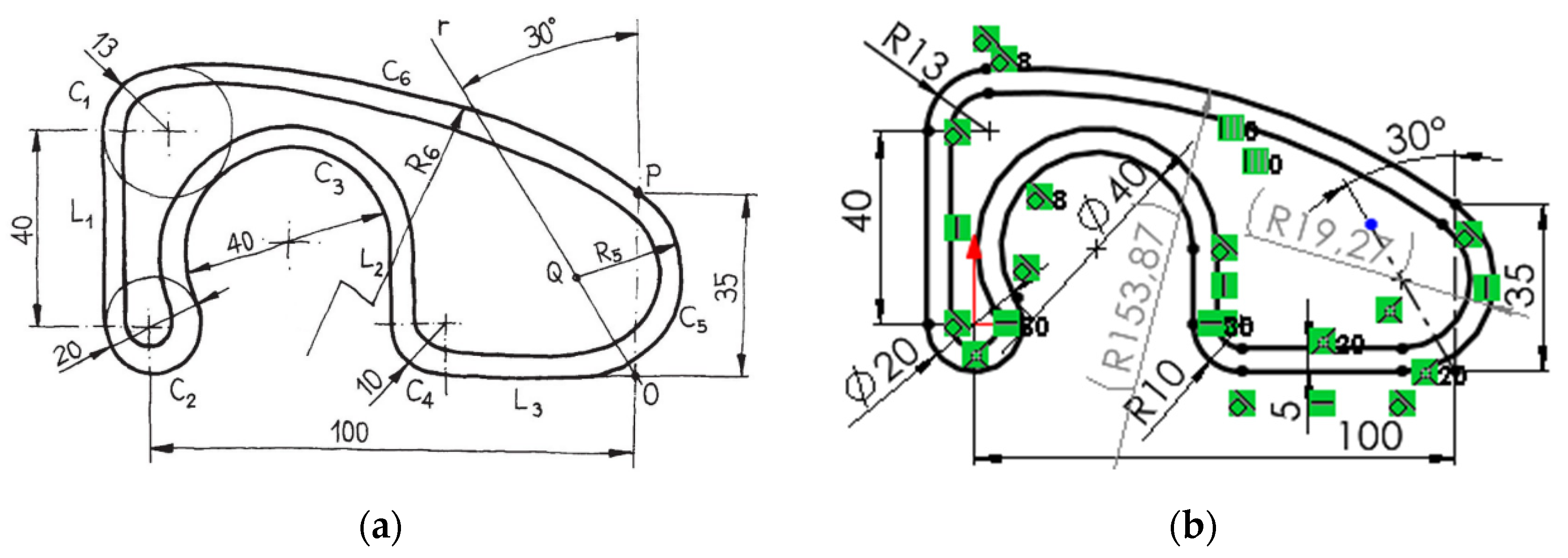
Figure 2.
Redesigns of a fully unconstrained profile, and failures in fixing the incorrect shapes.
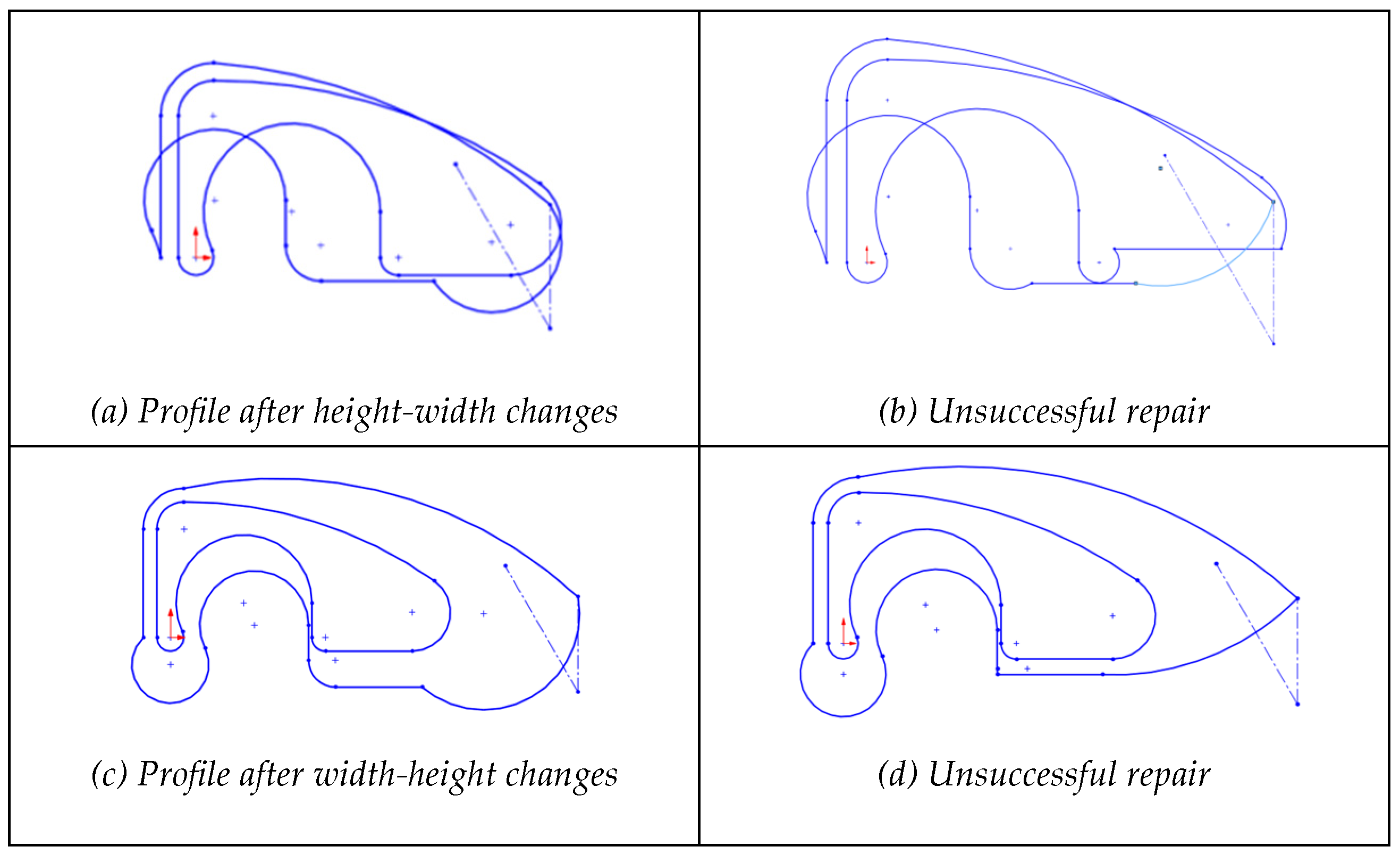
Figure 3.
Redesigns of a dimensionally unconstrained profile, and failures in fixing the incorrect shapes.
Figure 3.
Redesigns of a dimensionally unconstrained profile, and failures in fixing the incorrect shapes.
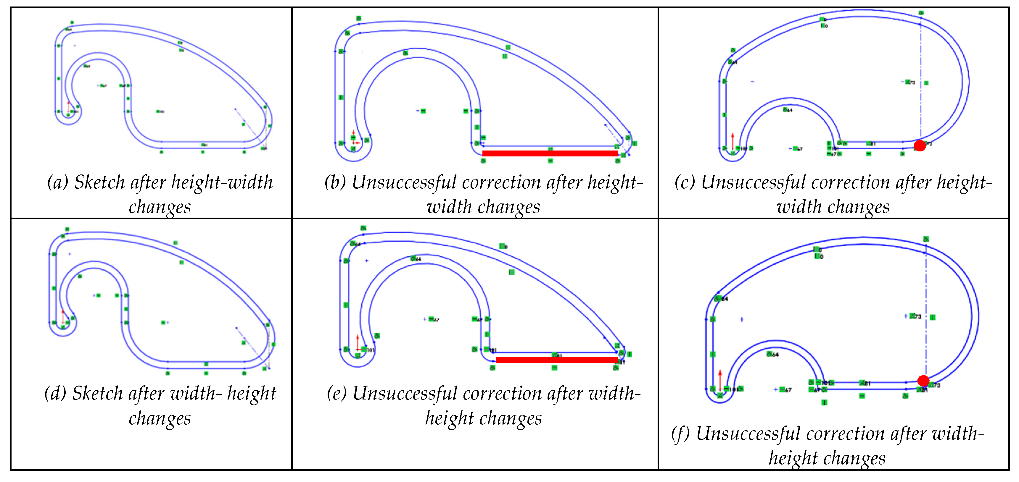
Figure 4.
Redesigns of a geometrically unconstrained profile plus some dimensions missing, and failures in fixing the incorrect shapes.
Figure 4.
Redesigns of a geometrically unconstrained profile plus some dimensions missing, and failures in fixing the incorrect shapes.
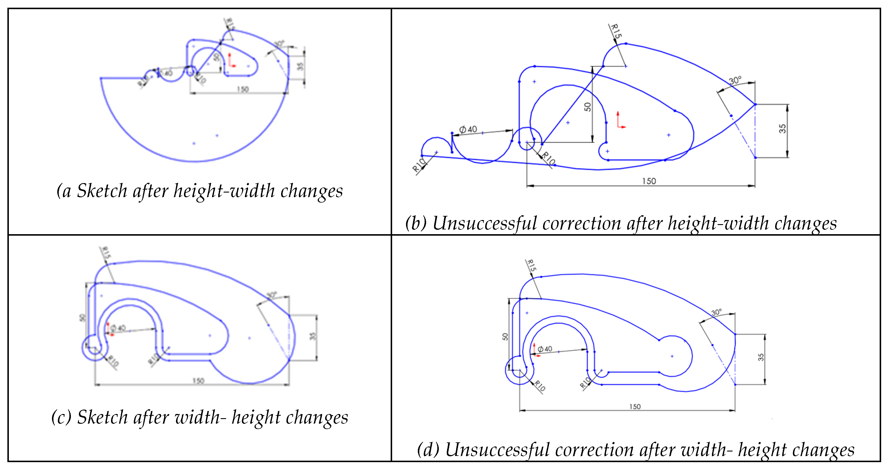
Figure 5.
Redesigns of a geometrically unconstrained profile, and failures in fixing the incorrect shapes.
Figure 5.
Redesigns of a geometrically unconstrained profile, and failures in fixing the incorrect shapes.
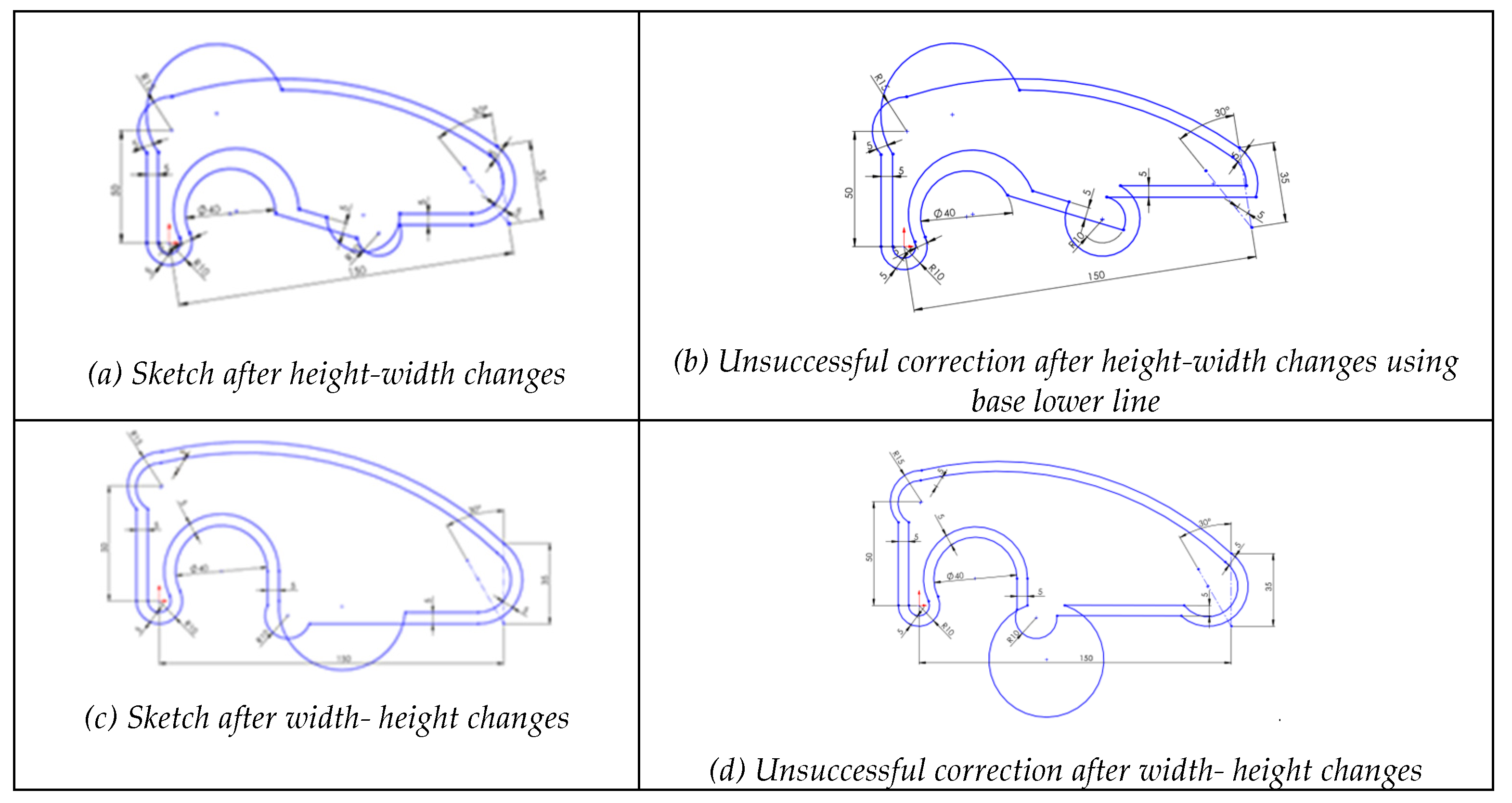
Figure 6.
Progressive deformation when applying changes (height-width) to sketch the effect of a sketch without tangent constraints.
Figure 6.
Progressive deformation when applying changes (height-width) to sketch the effect of a sketch without tangent constraints.
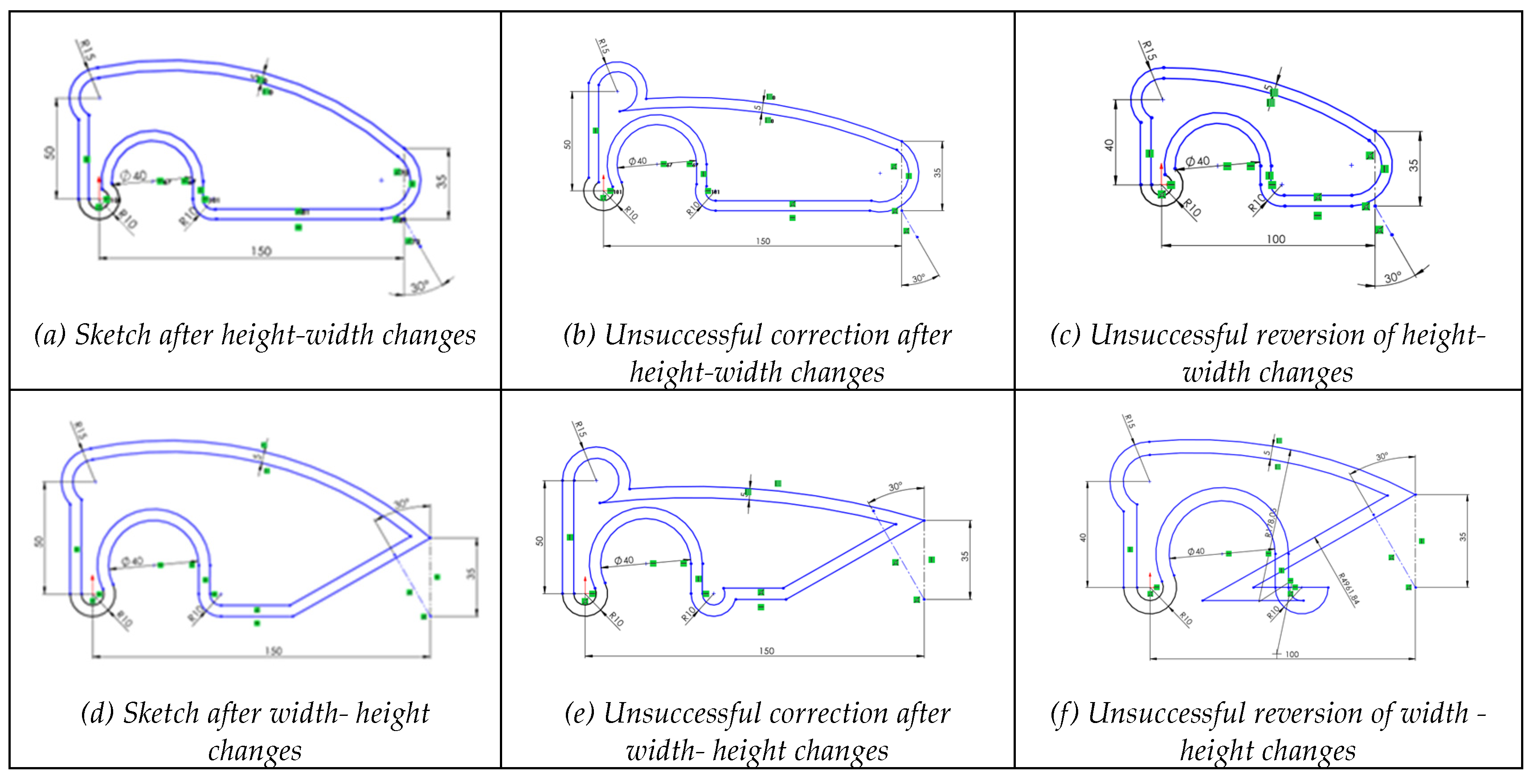
Figure 7.
Progressive deformation when applying changes (height-width) to sketch with selected dimensional and geometric constraints were removed.
Figure 7.
Progressive deformation when applying changes (height-width) to sketch with selected dimensional and geometric constraints were removed.

Figure 8.
Behavior of a sketch with geometric redundant constraints.
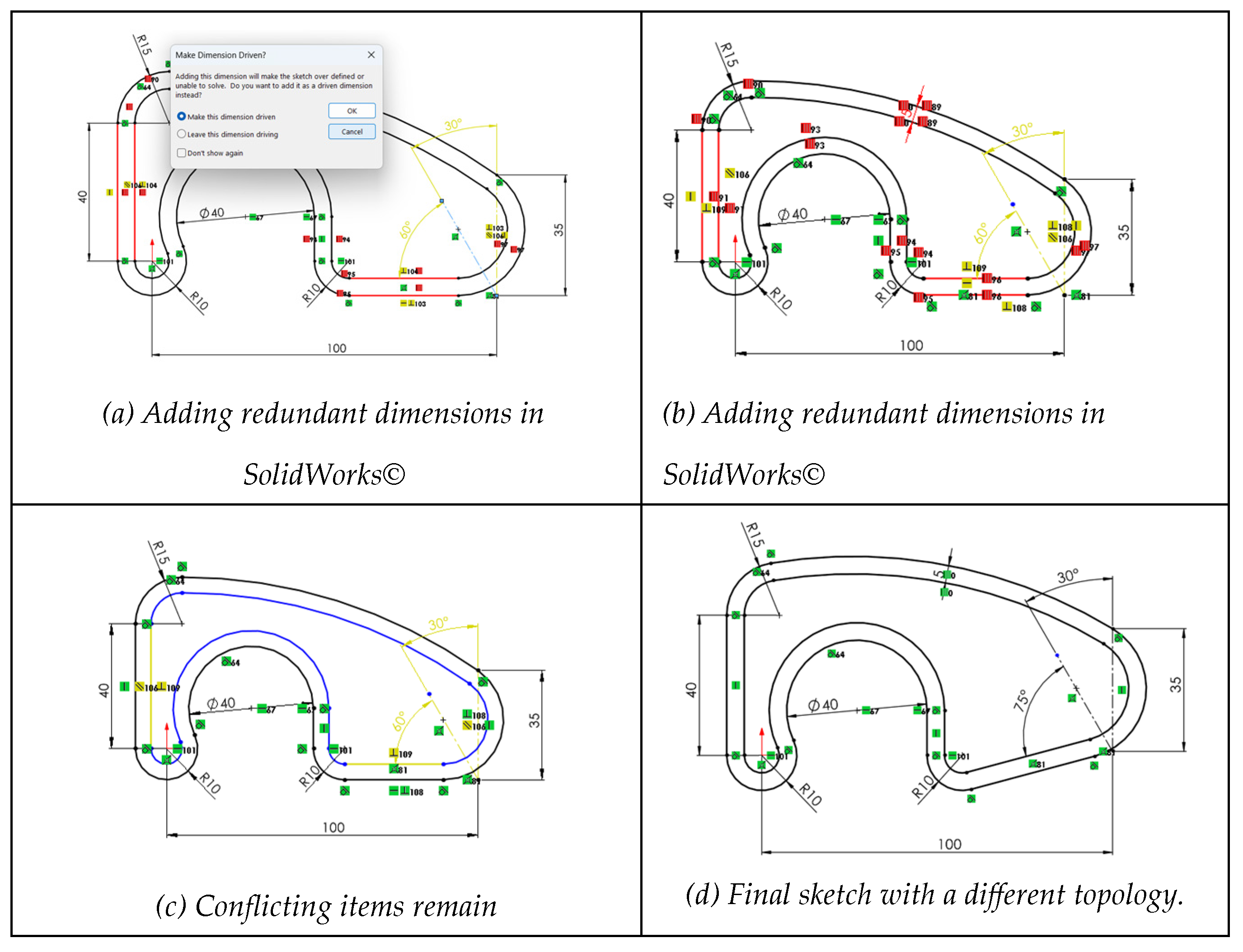
Figure 9.
Simulation of a sketch with incompatible constraints.

Figure 10.
Edition of a sketch with extrinsic constraints.
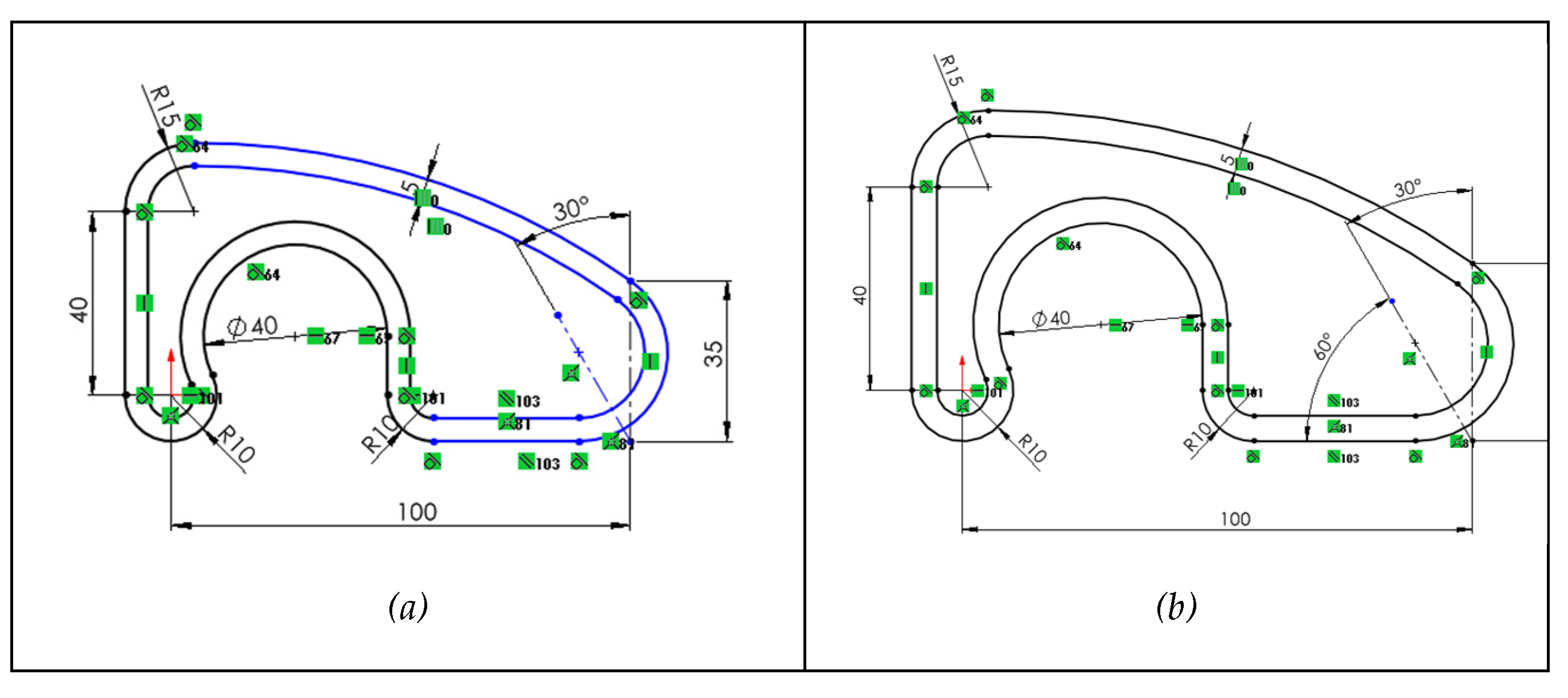
Figure 11.
Changing an irregular pentagon into a quadrilateral by removing a vertex.
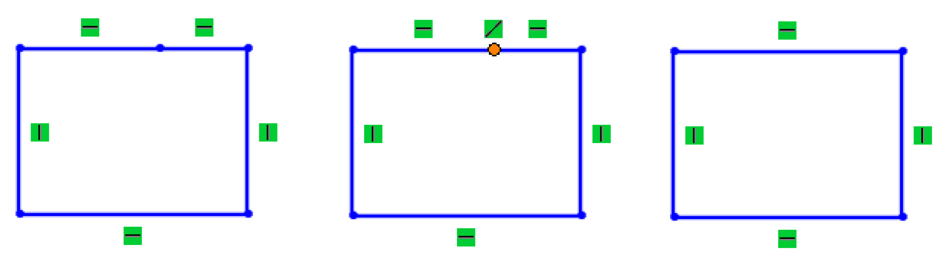
Figure 13.
Invalid profile after editing fragmented profile.
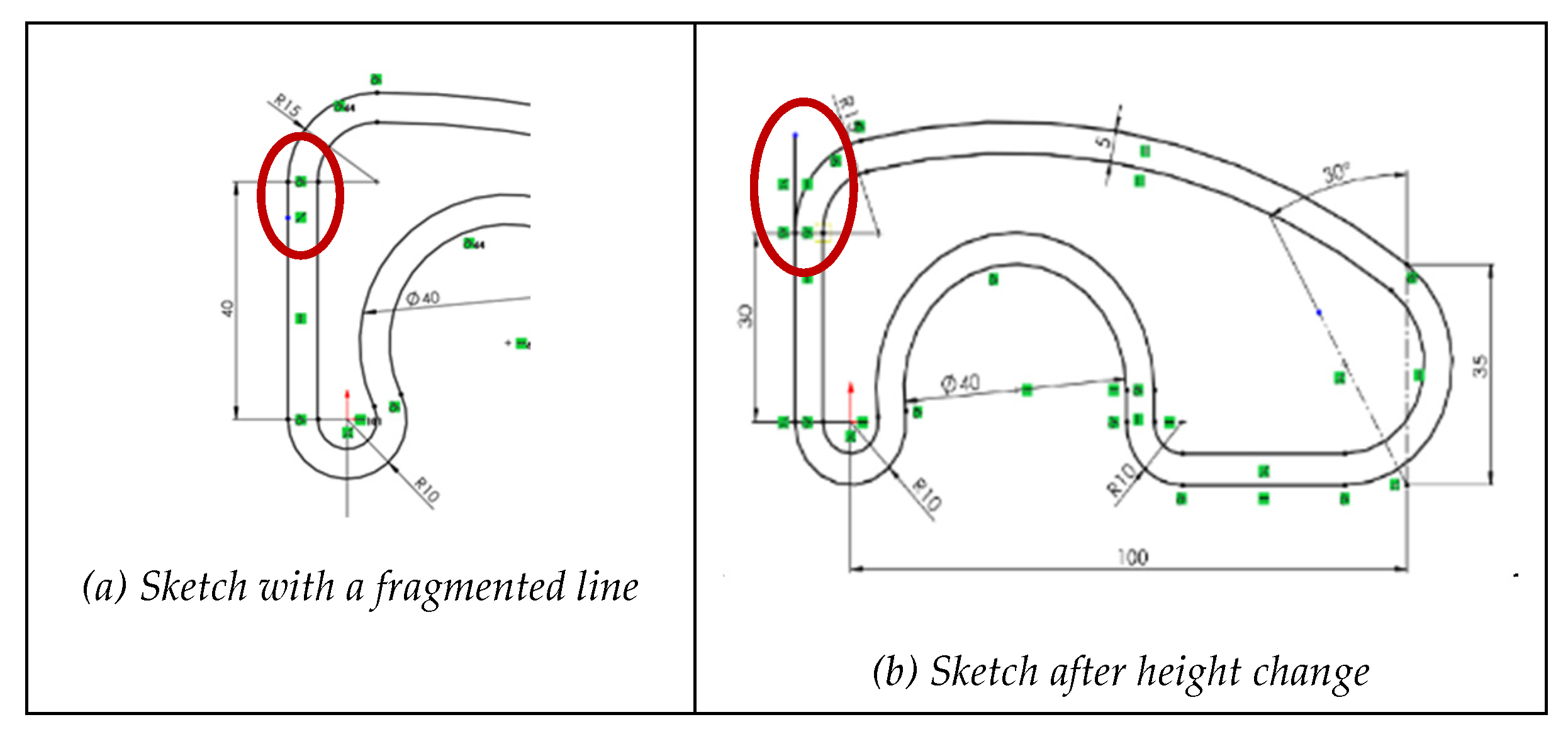
Figure 14.
Behavior of a sketch that contains a duplicate line.
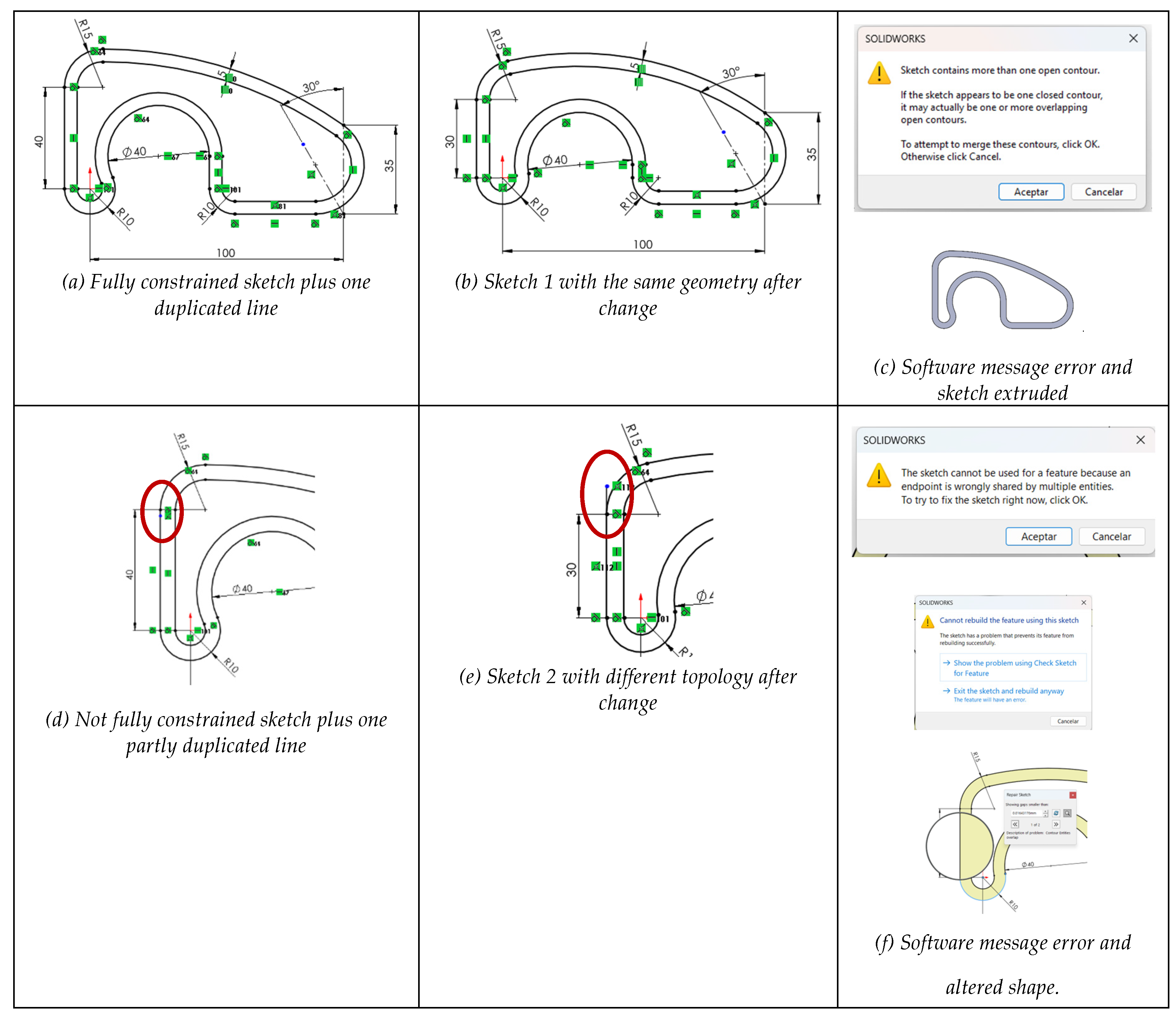
Figure 15.
Invalid profile after assigning incorrect line types.
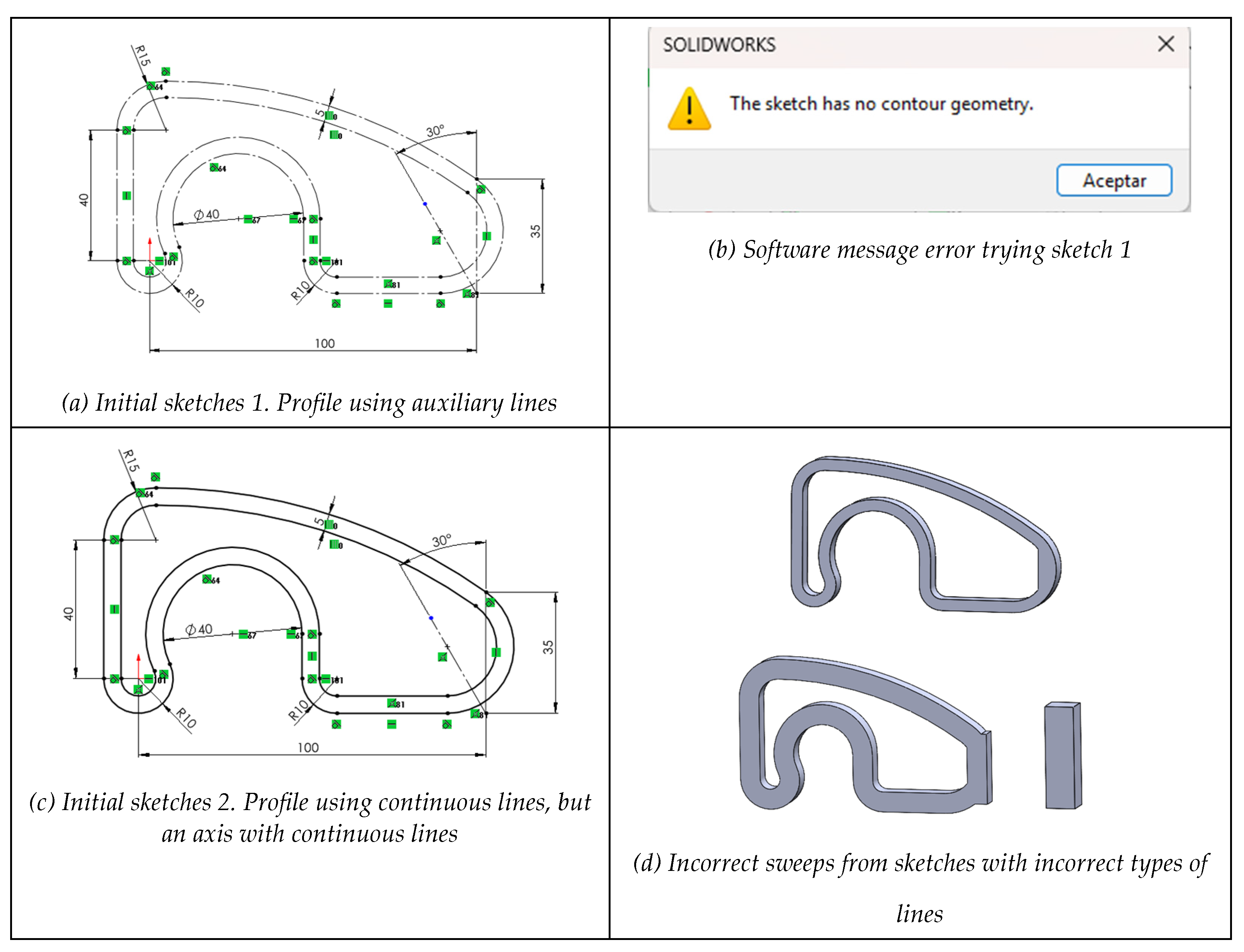

Table 1.
Errors related to reusability quality criteria.
| Quality item error | Quality sub-item error | Error description | Influence |
|---|---|---|---|
|
The model fails to be CONSISTENT Design changes typically cause unpredictable or potentially catastrophic results. |
Poorly drawn, or poorly constrained, profiles lead to design changes that produce unpredictable results. | Profiles are partially unconstrained or miss critical constraints. | S |
| Profiles have many (or at least some critical) segmented lines causing continuity issues. | S | ||
| Profiles have incorrect or duplicate lines (too many of them or at least some critical ones). | S | ||
| Model is incorrectly positioned relative to the references. | Model is not aligned or oriented to the global reference system. | D | |
| Model lacks suitable datums for building and editing. | D | ||
| Different functional elements are modeled together or unnecessarily interrelated. | Model-tree has an excess of unnecessary dependencies. | D | |
| Functional elements are not defined by independent modeling operations. | PMT | ||
|
The model fails to be CONCISE Model contains significant repetitive or fragmented constraints, datums and features, or does never use pattern operations, thus managing more geometry than strictly required to build and edit the model. |
The model includes many repetitive or fragmented constraints, datums or features, or at least one potentially catastrophic. | Profiles have excessive or critical repetitive/fragmented constraints. | S |
| Model has significant or critical repetitive or fragmented datums. | D | ||
| Model has significant or critical repetitive or fragmented features. | PMT | ||
| Workable replication operations (translate-and-repeat, rotate-and-repeat and symmetry) are never used in parts with patterns. | Workable pattern operations (translate-and-repeat, rotate-and-repeat) are never used. | PMT | |
| Workable modeling operations of symmetry are never used to define the model. | PMT |
Table 2.
Identification of the negative consequences of errors.
| Hypotheses | General negative knowledge | # | Detailed negative knowledge |
|---|---|---|---|
| Unconstraining sketches in general, and profiles in particular, negatively affects the quality of CAD models, while not all the missing or inappropriate constraints have the same negative impact on topology and geometry. | Profiles with no constraints are not reusable because they become unstable when edited. | H1 | Fully unconstrained profiles are non-reusable, as unpredictable alterations occur when edited. |
| H2 | Dimensional constraints mainly control size; thus, its absence easily derives in uncontrolled global inflation or deflation edition. | ||
| H3 | Geometric constraints mainly control shape; thus, its absence has a greater impact on reusability as edited models easily become globally tangled or distorted. | ||
| The loss of some constraints always reduces reusability, while intensity depends on the nature of the missing constraints. | H4 | Partial incompleteness of dimensional constraints easily derives in uncontrolled local inflation or deflation while editing. | |
| H5 | Partial incompleteness of geometric constraints easily derives in uncontrolled locally tangled or distorted shapes while editing. | ||
| H6 | Some constraints (mainly those restricting few and local degrees of freedom) have minor influence on topology, while retaining important influence on geometry variations during editing. | ||
| Overconstrained profiles, with excessive or incompatible constraints, are difficult to edit, and may become unusable. | Overconstraining affects reusability of sketches. | H7 | Overconstrained profiles are difficult to edit but still reusable if the surplus constraints are redundant. |
| H8 | Overconstrained profiles are non-reusable and even unusable if the surplus constraints are incompatible. | ||
| Some specific constraints always increase the risk of overconstraining. | H9 | Fix constraint (anchor) is prone to produce unintended restrictions when combined with dimensional constraints, thus limiting the ability to modify the design. | |
| H10 | Extrinsic constraints are more prone to overconstraining than their intrinsic counterparts. | ||
| Inconsistent geometry always affects profiles reusability. | Continuity issues result in hard editing profiles, which sometimes do not sweep to build features. | H11 | Broken C0 continuity in profiles typically prevent their usability as result in cracked shapes, or even sweep failures. |
| H12 | Profiles constrained to less than optimal continuity (fragmented continuity) results in extra constrained profiles that sometimes prevent sweeping features, while others aggravate edition. | ||
| Redundancies affect reusability of sketches. | H13 | Overlapping lines result in profiles that sometimes do not sweep to build features, while typically become unperceived and mistakenly edited. | |
| H14 | Tail lines result in profiles that typically cannot sweep to build features. | ||
| Incorrect assignment of line types (lines classification) makes geometry uninterpretable. | H15 | Import failures that result in overall incorrect line types making imported models neither reusable nor usable. | |
| H16 | Mistakenly changing some line types result in local inconsistencies that produce incorrect topologies when sweeping, or even failure to sweep. |
Disclaimer/Publisher’s Note: The statements, opinions and data contained in all publications are solely those of the individual author(s) and contributor(s) and not of MDPI and/or the editor(s). MDPI and/or the editor(s) disclaim responsibility for any injury to people or property resulting from any ideas, methods, instructions or products referred to in the content. |
© 2025 by the authors. Licensee MDPI, Basel, Switzerland. This article is an open access article distributed under the terms and conditions of the Creative Commons Attribution (CC BY) license (http://creativecommons.org/licenses/by/4.0/).
Copyright: This open access article is published under a Creative Commons CC BY 4.0 license, which permit the free download, distribution, and reuse, provided that the author and preprint are cited in any reuse.


