Submitted:
24 October 2025
Posted:
27 October 2025
You are already at the latest version
Abstract
Extrusion cutting is an intensive plastic deformation process developed from conventional cutting. To address issues such as high cutting temperatures and friction instability during machining, this study proposes integrating microtextured tools with extrusion cutting to optimize cutting performance. By designing distinct microtextured tools (parallel-to-cutting-edge microtextured tools (P-T) and perpendicular-to-cutting-edge microtextured tools (V-T)), cutting experiments were conducted on Al7075 alloy to systematically investigate the effects of microtextured extrusion cutting on cutting performance and chip formation. Results indicate that microtextured tools effectively reduce cutting temperatures; microtextured extrusion cutting suppresses serrated chip formation, stabilizing chip shaping; XRD analysis reveals that microtextured tools significantly increase chip dislocation density, enhancing microhardness and grain refinement. This study confirms that the combination of microtextured tools and extrusion cutting synergistically optimizes chip morphology and enhances microstructural properties in Al7075, providing technical support for machining high-strength aluminum alloys.
Keywords:
microtextured tools
; extrusion cutting
; chip morphology
; serrated chip
; microstructure
1. Introduction
Due to their high strength and low density, 7-series aluminum alloys are widely used in mechanical equipment manufacturing, transportation equipment, power system components, and aerospace engineering [1]. Their plastic properties lead to the formation of continuous long chips during machining, which can become entangled with the tool or workpiece. This causes scratches on the machined surface, reducing machining efficiency and safety.
Large Strain Extrusion Machining (LSEM) [2] employs restrictive blocks to macroscopically guide chip deformation pathways, effectively controlling chip morphology and refining material grain structure. However, when material enters the extrusion channel to form chips, cutting temperatures rise sharply. This not only accelerates tool wear and degrades chip material properties but also causes excessive friction at the tool-chip interface to impede material flow. This leads to machining instability and compromises chip morphology control.
Research by Efe et al. [3] indicates that after LSEM treatment, the microstructure of AZ31 magnesium alloy is significantly refined to an ultrafine grain level, with hardness nearly doubling compared to the original material. Sevier et al. [4] found that the compression ratio λ dominates strain distribution. A low compression ratio can induce ultra-high strain, significantly refining grains but accompanied by greater extrusion pressure, leading to increased tool-chip friction and making material extrusion more difficult. Deng et al. [5] experimentally and numerically confirmed that reduced compression ratio increases tool-chip friction, elevating equivalent strain and cutting temperature. This hinders material flow and triggers machining instability. Wang et al. [6] investigated through finite element analysis that adding microtexture to the tool surface during the extrusion cutting of 7A04 aluminum alloy can enhance the material's equivalent plastic strain and reduce cutting forces.
Micro-textured tools, as a novel surface modification technique, exhibit superior tribological and thermodynamic control capabilities by incorporating micrometer-scale grooves, pits, or other structures on the rake or flank faces [7]. Micro-textured tools primarily influence chip flow by acting on the tool-chip interface through micro-friction and micro-texture geometry, whereas extrusion cutting directly intervenes in the overall deformation path of the chip via macro-geometric constraints. The innovative integration of microtextured tools into extrusion cutting processes leverages their friction-reducing and heat-dissipating advantages to directly optimize extrusion cutting parameters, enabling more precise and effective control over chip morphology. Research on introducing microtexture technology into extrusion cutting and investigating its cutting performance and chip morphology remains scarce. The mechanisms by which tools influence cutting performance and chip morphology are still poorly understood. Therefore, using 7075 aluminum alloy as the subject, systematically comparing cutting temperatures, chip morphology, and microstructural evolution patterns during extrusion cutting using different microtextured tools (parallel-to-cutting-edge microtextured tools(P-T) and perpendicular-to-cutting-edge microtextured tools (V-T)). This provides new insights for overcoming extrusion cutting process bottlenecks and achieving efficient machining of high-performance aluminum alloys.
2. Principle of High-Strain Extrusion Cutting
Large-strain extrusion cutting is a strip processing method that combines cutting with extrusion. This technique utilizes an extrusion mechanism to expel chips, yielding nanomaterials with regular geometric shapes, uniform internal structures, and high strength [8]. The working principle is illustrated in Figure 1. A restrictive block is added to conventional cutting. Under the combined squeezing force of the cutting tool and the restrictive block, the workpiece is extruded along the channel formed by both components to create chips. During this process, the metal in the cutting layer undergoes severe plastic deformation due to the dual effects of cutting and extrusion.
The resulting shear strain is :
Strain rate is:
Shear angle is:
In the formula: a is the rake angle of the cutting tool; λ is the chip thickness compression ratio, defined as the ratio of chip thickness to cutting layer thickness [9], i.e.:
3. Experiments and Methods
3.1. Preparation of microtextured tools
This study employs laser processing to create microtextures on tool surfaces. A fiber laser marking machine (YDFLP-20-LP-S model, Dezhong Laser) was used to fabricate microtextures on cemented carbide. Processing parameters were: laser scanning speed 10 mm/s, frequency 800 kHz, scanning count 5 times, power setting 63%. Two tool types were produced: P-T tools with texture direction parallel to the cutting edge and V-T tools with texture direction perpendicular to the cutting edge. The texture parameters are: pitch 50 μm, depth 50 μm, and width 40 μm, as shown in Figure 2.
3.2. Extrusion Cutting Experiment
The experimental material selected was 7075-T6 aluminum alloy tubing with an outer diameter of 60 mm and an inner diameter of 55 mm. Its chemical composition was as follows: 5.6% Zn, 2.50% Mg, 1.6% Cu, 0.5% Fe, 0.40% Si, 0.30% Mn, 0.23% Cr, 0.20% Ti, with the remainder being Al. The cutting tool was made of cemented carbide material.
The extrusion cutting experiments in this study were conducted on a CA6140 lathe. The workpiece material was clamped in the lathe, while the combined tooling was secured to the lathe tool holder, as shown in Figure 3(a). The combined tooling assembly is depicted in Figure 3(b). The tool holder, cutting tool, and limiting block of this assembly are all bolted connections, allowing for disassembly. This facilitates timely handling of issues such as chip jamming and enables the replacement of cutting tools at any time, thereby altering the type of cutting tool employed. All cutting tools used in the experiment featured a 10° front angle and a 5° rear angle. The feed rate was fixed at 0.69 mm/r, with a depth of cut of 0.5 mm and a compression ratio of 1.4. Experiments were conducted at different cutting speeds: 78, 156, 328, and 656 mm/s.
In the turning experiments, the HIKMICRO-TM series handheld high-frame-rate infrared thermometer from Hikmicro was employed to capture high-temperature data during the extrusion cutting process using non-contact thermal imaging technology. The surfaces of the prepared chip specimens were polished to a mirror finish using a metallographic specimen polishing machine (Model MP-2). During polishing, the specimen surface underwent coarse polishing followed by refinement using diamond polishing discs ranging from 800 to 1500 grit. Finally, metallographic polishing compounds from 5.00 μm to 0.25 μm were applied to achieve a mirror finish [10]. The specimenwas ultrasonically cleaned for 15 minutes, and the polished surface was etched using Keller's reagent solution. Finally, the cross-sectional morphology of the chips was observed using a Leica DFC320 digital metallographic microscope. The longitudinal geometric parameters of the chips were measured and annotated using a super-depth-of-field microscope. The surface hardness of the chips was tested using an automatic turret digital display Vickers hardness tester (Model HVS-30Z, Shanghai Lianer Testing Equipment Co., Ltd.). The load was set at 500g, held for 10 seconds, with 10 points tested at different locations on each specimen. The average value was taken as the hardness value. The prepared chips were mechanically ground and electrolytically polished to form test specimens measuring 10 × 10 × 2 mm³. X-ray diffraction analysis was performed on each chip using an XRD instrument. The scanning range was set to 20°–90° with a step size of 0.02° and a scanning speed of 4°/min for phase analysis of the chips.
4. Results and Analysis
4.1. Cutting Temperature
Under constant conditions of feed rate f = 0.69 mm/s, depth of cut ap =0.5mm, and compression ratio λ = 1.4, real-time temperatures were recorded for three tool types at different rotational speeds. Ten sets of measurements were taken at each speed, and thermal imaging data were analyzed.
Figure 4 shows the average of the maximum temperature values. The experimental data indicate that cutting temperature is positively correlated with cutting speed, and the temperatures during extrusion cutting with microtextured tools are consistently lower than those with non-textured tools. At v=78 mm/s and v=156 mm/s, the average cutting temperatures of all three tools were roughly equivalent. This occurs because at low speeds, the chip flow velocity is low, making aluminum alloy cutting prone to producing continuous ribbon chips. At these speeds, the chip-storing function of microtexture is suppressed, the interaction pattern between the chip and the textured grooves changes, and the friction coefficient increases which intensifies secondary scraping of the tool surface by the chip. When the workpiece speed increases to v=328 mm/s and v=656 mm/s, the average cutting temperatures of both P-T and V-T tools are significantly lower than that of the N-T tool, demonstrating their advantage in reducing cutting temperatures[11]. Compared to N-T tools, P-T tools and V-T tools can reduce the maximum cutting temperature by an average of 8.22% and 8.97%, respectively, with maximum reductions reaching 13.20% and 13.02%, respectively.
Microtextures guide chip flow along specific directions—namely, along the texture orientation—thereby reducing chip adhesion time on the tool surface and minimizing the formation of localized high-temperature zones. Additionally, microtextures enhance heat transfer efficiency to the surrounding environment by increasing the effective heat dissipation area on the tool surface [12].
4.2. Chip Morphology
Under fixed conditions of feed rate (f = 0.69 mm/s), depth of cut (ap =0.5mm), and compression ratio (λ = 1.4), the cross-sectional morphology of chips generated by three tool types (N-T, P-T, V-T) during Al7075 machining at different cutting speeds was systematically observed, as shown in Figure 5. The results indicate that at low cutting speeds of v=78 mm/s and v=156 mm/s, the chips produced by all three tools exhibited no distinct serrated features, instead forming continuous ribbon-like structures with wavy patterns.
This stems from uniform material deformation, lower temperatures in the shear zone, and stable plastic flow, resulting in continuous ribbon-like chips. As cutting speed increases, serration gradually intensifies [13]. Comparing the serration phenomena among the three tools, the N-T tool exhibited more pronounced serrations than the P-T and V-T tools. This occurs because increased cutting speed elevates strain and strain rate, intensifying deformation. Concentrated shear slip then causes a sharp rise in cutting temperature, leading to more evident chip serration [14]. Combined with the aforementioned ability of microtextured tools to reduce cutting temperatures, this indicates that microtextured tools can suppress the formation of serrations in chips.
Adiabatic Shear Theory [15] posits that during chip formation, workpiece material undergoes plastic deformation due to compression. When this plastic deformation causes localized temperature increases in the workpiece material, leading to thermal softening exceeding the material's strain hardening, adiabatic shear occurs. Under the alternating effects of thermal softening and strain hardening, periodic shear bands [16] form in the material. Parameters describing the serration morphology include serration degree Gs, serration pitch Pc, adiabatic shear band spacing d, rake angle α1, and clearance angle α2, as shown in Figure 6. The degree of serration in serrated chips can be expressed in two forms. We adopt the serration degree Gs definition proposed by Schulz H. et al [17], calculated as follows:
where h1 is the tooth crest height, h2 is the tooth root height, and a larger Gs value indicates a more severe degree of serration in the serrated chips.
Due to the low yield strength of Al7075 (approximately 500 MPa) and its uniform plastic deformation, the serration coefficient is relatively small, resulting in less pronounced serration during low-speed cutting. Therefore, chips from two speed groups—v=328 mm/s and v=656 mm/s—were selected for measurement. The serration coefficient Gs and tooth pitch Pc were statistically analyzed and averaged.
Figure 7 shows the variation of chip serration with cutting speed. Comparison reveals that under identical speed conditions, chips produced by both microtextured tools exhibit lower serration than those from conventional tools at the same speed. At both cutting speeds, the serration values for standard tool chips were 0.366 and 0.643, while microtextured tool chips showed values of 0.355 and 0.569 for P-T chips and 0.352 and 0.478 for V-T chips. Both microtextured tools produced chips with lower serration than the non-textured tool. Compared to the N-T tool, the P-T chip serration decreased by 3.01% and 11.51%, while the V-T chip serration decreased by 3.83% and 25.66% . As shown in Figure 7(a), the serration degree of chips gradually increases with rising cutting speed. Higher speeds generate more friction heat, intensify extrusion deformation, and exacerbate shear slippage, resulting in more pronounced serration patterns. Figure 7(b) presents the statistical distribution of chip serration pitch (Pc). It is evident that the serration pitch of chips produced by all three tools gradually increases with cutting speed. Higher cutting speeds elevate strain rate and local temperature, intensifying adiabatic shear localization and consequently widening the serration pitch. Furthermore, comparing microtextured tools with conventional tools reveals that the serration spacing is larger for microtextured tools. This is because microtextured tools reduce the contact area with the chip during contact, lowering temperature, decreasing plastic deformation, and relatively weakening slip phenomena, thereby suppressing serrations [18]. Comparing tooth spacing values at different cutting speeds reveals that the difference between microtextured and conventional tools is greatest at 656 mm/s. This indicates that microtexturing more effectively suppresses tooth formation at this speed, thereby improving chip formation.
4.3. Microstructure of Chips
Figure 8 shows the chip morphology observed under a metallurgical microscope at a cutting speed of v = 656 mm/s. Analysis indicates that the serrated chips exhibit a typical periodic adiabatic shear band structure. The shear band width ranges from approximately 60 to 90 μm. Significant grain refinement is observed within the shear bands, where primary grains are elongated into fibrous structures along the shear direction. Localized regions exhibit ultrafine equiaxed grains (<2 μm) formed by dynamic recrystallization.
Comparing the hardness of the chip matrix zone and shear slip zone produced by three different tools, experimental data demonstrate that varying degrees of plastic deformation across different regions result in differing chip hardness. Organizing the measured results, the line graph in Figure 9 shows that for the same tool under identical feed rate and depth of cut conditions, chip hardness gradually decreases with increasing cutting speed. The rate of hardness reduction also diminishes as rotational speed increases, attributed to the narrowing gap between material strain hardening and thermal softening effects. Comparing identical parameters, the hardness in the shear slip zone consistently exceeds that of the matrix region. This is attributed to severe compression slip in the shear slip zone, which enhances hardness [19]. The shear zone exhibits a hardness 10-20% higher than the matrix. Chips produced by microtextured tools generally demonstrate higher hardness than those from conventional tools.
XRD phase analysis of chips produced by microtextured and conventional non-textured tools at a cutting speed of 656 mm/s is shown in Figure 10.
Al7075 belongs to the Al-Zn-Mg-Cu series of alloys, with the precipitation sequence being: supersaturated solid solution—GP zone—ηʹ(MgZn)—η(MgZn₂). Figure 10 shows a small peak near 2θ = 42° in the N-T tool chip sample, corresponding to the MgZn₂ precipitation phase—the η' phase transformed from the GP region. This peak is very weak in the microtextured tool (P-T and V-T) chip samples. XRD phase analysis indicates that the volume fraction of η' phase (MgZn₂) in chips decreases with microtextured tools compared to untwisted tools. Four characteristic diffraction peaks were identified: (111), (200), (220), and (311) corresponding to α-Al crystal planes. Comparing the three sets of XRD patterns, the angular shifts of the main Al phase diffraction peaks (111, 200, 220) among the three tools were minimal, indicating insignificant lattice constant changes and negligible residual stress differences. Chips produced by the three tools exhibit regular fluctuations in peak intensity. Due to preferential orientation during hot extrusion deformation, the intensity of the (200) crystal plane diffraction peak varies, showing both strong and weak signals. The groove texture grooves on microtextured tools induce multidirectional slip during chip sliding, thereby reducing the (111) peak intensity. Microtexture may cause anisotropy in the mechanical properties of chips, while the random orientation of microtextured tools helps improve material uniformity.
Under extrusion cutting processes, the core microstructural features within metallic materials manifest as high-density dislocation networks.The proliferation and evolution of dislocations. Precise characterization of dislocation density and the establishment of computational models are crucial for analyzing microstructural evolution patterns and quantitatively assessing dislocation strengthening mechanisms [20]. Based on crystal plasticity theory, the dislocation density in materials after extrusion and cutting can be calculated using the following equation [21,22]:
where b is the Burgers vector with a value of 0.286 nm; represents the material's microstrain; denotes the grain size. These parameters can be calculated using the full width at half maximum (FWHM) of the XRD diffraction peak [23]. FWHM β consists of two components: grain size-induced broadening β1 and microstrain-induced broadening β2. These can be estimated using the Cauchy and Gaussian equations, respectively. Combining Scherrer and Wilson's methods yields the formula [24]:
where,
:Half-width at half maximum of the diffraction peak;
: Half-diffraction angle;
λ: X-ray wavelength, λ=0.15405 nm.
Measurements of the positions and half-widths of the four strongest peaks (111), (200), (220), and (311) in the chip specimens produced by N-T, P-T, and V-T tools were conducted. Let represent y in the binary linear equation, as x , with the slope of the line being 1/ and the intercept being 16. Substituting the measured values into the equation yields and , with specific data shown in Table 1 and Figure 11. Substituting these values into the formula, the dislocation densities for N-T, P-T, and V-T chip specimens are determined to be 2.68×10¹⁴ m-2, 4.42×10¹⁴ m-2, and 1.01×10¹⁵ m-2, respectively. Compared to N-T tools, microtextured tools produce smaller grain sizes during cutting. This is because microtextured tools effectively reduce the friction coefficient in the tool-chip contact zone, thereby minimizing heat accumulation during cutting. Additionally, the lubricating effect of microtexturing reduces cutting force fluctuations and decreases grain elongation deformation [25].
5. Conclusions
- Microtextured tools effectively reduce cutting temperatures. Compared to N-T tools, P-T tools and V-T tools can reduce the maximum cutting temperature by an average of 8.22% and 8.97%, respectively, with maximum reductions reaching 13.20% and 13.02%, respectively. Microtextures guide chip flow orientation, reducing viscous contact time at the tool-chip interface while increasing the tool's effective heat dissipation area and enhancing thermal conductivity efficiency.
- Microtextured tools suppress serrated chip formation. Under identical cutting conditions, chips produced by P-T and V-T tools exhibit lower serration degree (Gs) than N-T tools (maximum reductions of 11.51% and 25.66%, respectively), with increased serration spacing that enhances chip formation stability.
- Microtextured tools enhance the microhardness of chip microstructure. Chips produced by microtextured tools exhibit higher microhardness in both shear slip zones and matrix regions compared to those from N-T tools.
- Microtextured cutting tools can increase the dislocation density in chips. XRD analysis indicates that microtextured tools (particularly V-T) significantly enhance the dislocation density in chips (V-T: 1.01×10¹⁵m⁻², P-T: 4.42×10 14m⁻²; N-T: 2.68×10¹⁴ m⁻²), thereby enhancing material strength.
- Microtextured tools can optimize the extrusion cutting process. This study confirms that introducing microtextured tools into the extrusion cutting process effectively overcomes challenges such as high cutting temperatures and significant tool-chip friction. Microtexturing optimizes the extrusion cutting process of Al7075 across multiple levels—tribology, thermodynamics, and microstructural evolution—by reducing friction, promoting heat dissipation, guiding chip flow, suppressing serration formation, refining grain size, and increasing dislocation density.
Author Contributions
Xiaolong Yin: Conceptualization, Methodology, Investigation, Writing—original draft, Writing—review and editing.; Minghui Yang: Methodology, Investigation, Writing-original draft; Wan Wang: Methodology,Investigation, Data curation,; Youhua Li: Supervision, Investigation, Data curation; Yuying Li: Supervision, Investigation, Data curation.
Funding
This research was founded by the National Natural Science Foundation of China (No. 52105499), Young Backbone Teacher Support Program of Zhongyuan University of Technology (No. 2024XQG09), Discipline Youth Master’s Guidance Training Program of Zhongyuan University of Technology ( No. SD202406), Fundamental Research Funds for Zhongyuan University of Technology (No.K2022YY001), Key Scientific Research Projects of Colleges and Universities in Henan Province (No. 26A460031) and Key Research and Development Program of Henan Province (No. 241111220100).
Data Availability Statement
The raw data supporting the conclusions of this article will be made available by the authors on request.
Conflicts of Interest
The authors declare no conflicts of interest.
References
- Zhou, B.; Liu, B.; Zhang, S.G. The Advancement of 7XXX Series Aluminum Alloys for Aircraft Structures: A Review. Metals 2021, 11. [Google Scholar] [CrossRef]
- Gurusamy, M.; Rao, B.C. A Comprehensive Review of Large-Strain-Extrusion Machining Process for Production of Fine-Grained Materials. Crystals 2023, 13. [Google Scholar] [CrossRef]
- Efe, M.; Moscoso, W.; Trumble, K.P.; Compton, W.D.; Chandrasekar, S. Mechanics of large strain extrusion machining and application to deformation processing of magnesium alloys. Acta Materialia 2012, 60, 2031–2042. [Google Scholar] [CrossRef]
- Sevier, M.; Yang, H.T.Y.; Moscoso, W.; Chandrasekar, S. Analysis of severe plastic deformation by large strain extrusion machining. Metallurgical and Materials Transactions a-Physical Metallurgy and Materials Science 2008, 39A, 2645–2655. [Google Scholar] [CrossRef]
- Deng, W.J.; Lin, P.; Xie, Z.C.; Li, Q. Analysis of Large-Strain Extrusion Machining with Different Chip Compression Ratios. Journal of Nanomaterials 2012, 2012. [Google Scholar] [CrossRef]
- Wang, P.H.; Yue, X.J.; Zong, C.G.; Zhang, P.; Zhang, Q.; Zhai, Y.C.; Yu, X.A. Research on the influence of tool geometric parameters on the LSEM mechanism of 7A04 aluminum alloy. Vacuum 2021, 192. [Google Scholar] [CrossRef]
- Wang, Q.W.; Yang, Y.; Yao, P.; Zhang, Z.Y.; Yu, S.M.; Zhu, H.T.; Huang, C.Z. Friction and cutting characteristics of micro-textured diamond tools fabricated with femtosecond laser. Tribology International 2021, 154. [Google Scholar] [CrossRef]
- Pi, Y.Y.; Deng, W.J.; Zhang, J.Y.; Yin, X.L.; Xia, W. Towards understanding the microstructure and temperature rule in large strain extrusion machining. Advances in Manufacturing 2021, 9, 262–272. [Google Scholar] [CrossRef]
- Yin, X.L.; Wang, W.; Wang, Z.L.; Guo, R.Y.; Yu, H.C.; Pi, Y.Y.; Yan, W.J.; Wang, H.B.; Zhou, H.B. Thermal stability, microstructure evolution and grain growth kinetics of ultrafine grained Al 7075 alloy processed by cryogenic temperature extrusion machining. Journal of Alloys and Compounds 2023, 950. [Google Scholar] [CrossRef]
- Yin, X.L.; Wang, Z.L.; Yu, H.C.; Wang, W.B. Microstructure, aging behavior, and friction and wear properties of ultrafine-grained 7050 aluminum alloy produced by cryogenic temperature extrusion machining. Materials Today Communications 2024, 39. [Google Scholar] [CrossRef]
- Jahaziel, R.B.; Krishnaraj, B.; Priyadarshini, B.G. G. Investigation on influence of micro-textured tool in machining of Ti-6Al-4V alloy. Journal of Mechanical Science and Technology 2022, 36, 1987–1995. [Google Scholar] [CrossRef]
- Rosas, J.; Lopes, H.; Guimaraes, B.; Piloto, P.A.G.; Miranda, G.; Silva, F.S.; Paiva, O.C. Influence of Micro-Textures on Cutting Insert Heat Dissipation. Applied Sciences-Basel 2022, 12. [Google Scholar] [CrossRef]
- Ye, G.G.; Chen, Y.; Xue, S.F.; Dai, L.H. Critical cutting speed for onset of serrated chip flow in high speed machining. International Journal of Machine Tools & Manufacture 2014, 86, 18–33. [Google Scholar] [CrossRef]
- Ding, F.; Zhang, T.; Wang, C.Y.; Sui, J.B.; Zhu, X.G.; Gao, K. Mechanism of chip segmentation transition from shear slip to shear fracture of Zirconium-based bulk metallic glass in mechanical machining. Journal of Materials Research and Technology-Jmr&T 2024, 30, 7398–7412. [Google Scholar] [CrossRef]
- Le, K.C.; Tran, T.M.; Langer, J.S. Thermodynamic dislocation theory of adiabatic shear banding in steel. Scripta Materialia 2018, 149, 62–65. [Google Scholar] [CrossRef]
- Rowe, R.A.; Allison, P.G.; Palazotto, A.N.; Davami, K. Adiabatic Shear Banding in Nickel and Nickel-Based Superalloys: A Review. Metals 2022, 12. [Google Scholar] [CrossRef]
- Schulz, H.; Abele, E.; Sahm, A. Material aspects of chip formation in HSC machining. Cirp Annals-Manufacturing Technology 2001, 50, 45–48. [Google Scholar] [CrossRef]
- Fan, L.; Deng, Z.L.; He, Y.; Zhu, X.L.; Gao, X.J.; Jin, Z. The effects of micro-texture shape on serrated chip geometry in the hardened steel AISI D2 cutting process. Surface Topography-Metrology and Properties 2022, 10. [Google Scholar] [CrossRef]
- Duan, C.Z.; Wang, M.J. Characteristics of adiabatic shear bands in the orthogonal, cutting of 30CrNi3MOV steel. Journal of Materials Processing Technology 2005, 168, 102–106. [Google Scholar] [CrossRef]
- Li, Z.; Zhao, P.C.; Lu, T.W.; Feng, K.; Tong, Y.G.; Sun, B.H.; Yao, N.; Xie, Y.; Han, B.L.; Zhang, X.C.; et al. Effects of post annealing on the microstructure, precipitation behavior, and mechanical property of a (CoCrNi)94Al3Ti3 medium-entropy alloy fabricated by laser powder bed fusion. Journal of Materials Science & Technology 2023, 135, 142–155. [Google Scholar] [CrossRef]
- Zhang, B.B.; Yan, F.K.; Zhao, M.J.; Tao, N.R.; Lu, K. Combined strengthening from nanotwins and nanoprecipitates in an iron-based superalloy. Acta Materialia 2018, 151, 310–320. [Google Scholar] [CrossRef]
- Zhao, Y.H.; Liao, X.Z.; Cheng, S.; Ma, E.; Zhu, Y.T. Simultaneously increasing the ductility and strength of nanostructured alloys. Advanced Materials 2006, 18, 2280. [Google Scholar] [CrossRef]
- Arvapalli, S.S.; Miryala, M.; Sakai, N.; Murakami, M.; Jirsa, M. Novel ultra-sonic boron refinement in distilled water for cost-efficient fabrication of MgB2 bulk ceramic superconductors. Ceramics International 2022, 48, 28102–28111. [Google Scholar] [CrossRef]
- Pang, J.J.; Liu, F.C.; Liu, J.; Tan, M.J.; Blackwood, D.J. Friction stir processing of aluminium alloy AA7075: Microstructure, surface chemistry and corrosion resistance. Corrosion Science 2016, 106, 217–228. [Google Scholar] [CrossRef]
- Roushan, A.; Chetan, *!!! REPLACE !!!*. Effect of discrete and continuous texture geometries on tool wear and derivative cutting effect during the machining. Wear 2025, 568. [Google Scholar] [CrossRef]
Figure 1.
Principle of large-strain extrusion cutting.
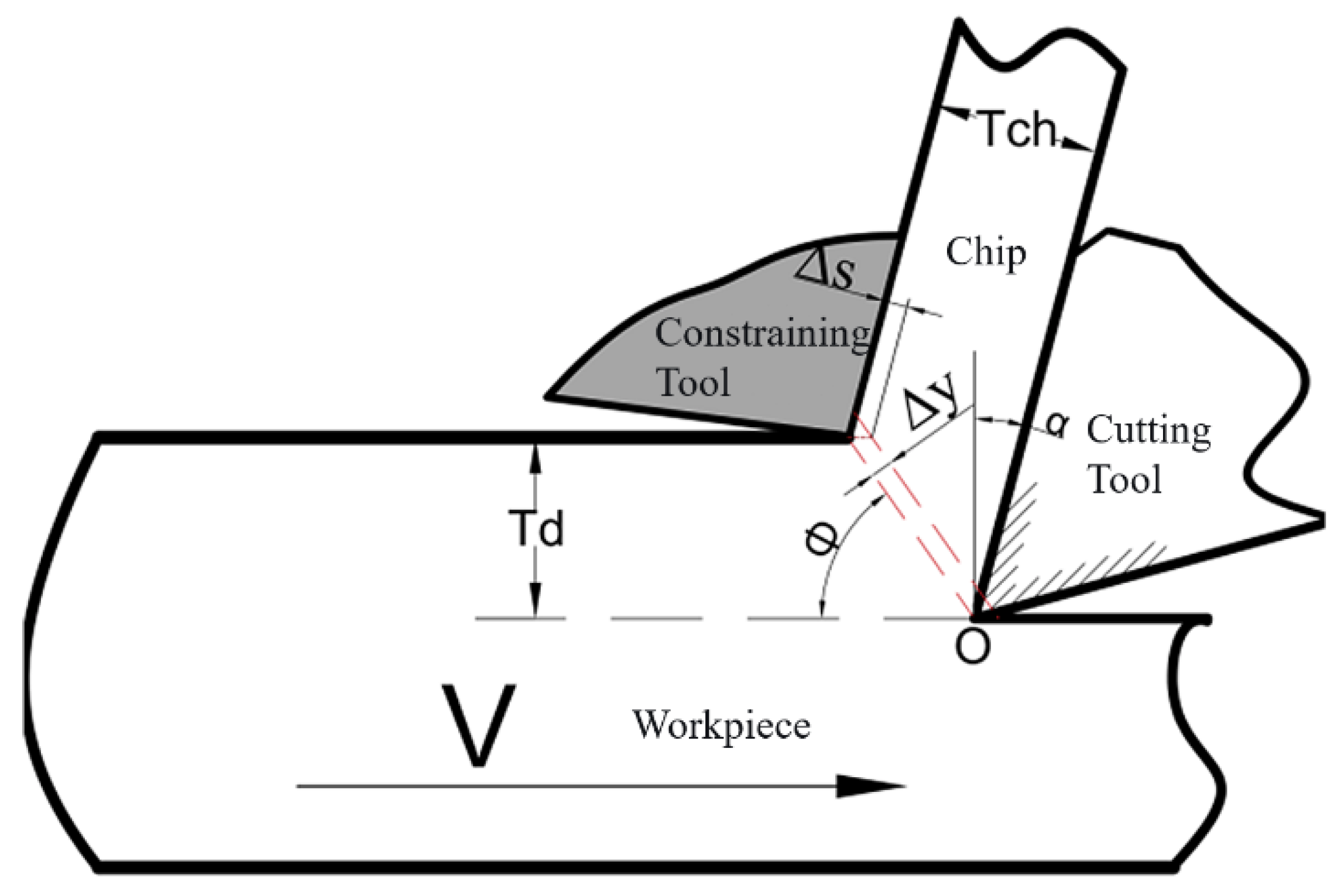
Figure 2.
SEM scan of tool front face microtexture: (a) P-T tool; (b) V-T tool
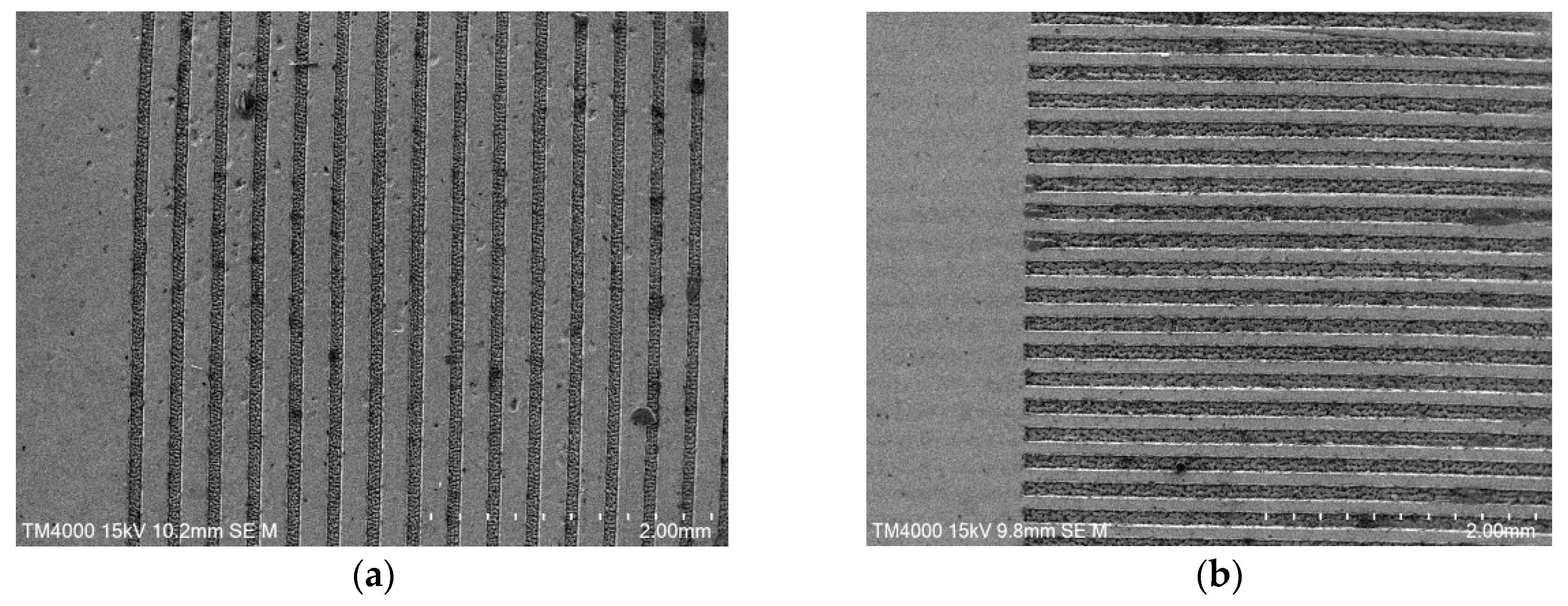
Figure 3.
Extrusion cutting experimental setup: (a) CA6140 lathe; (b) combination tool.
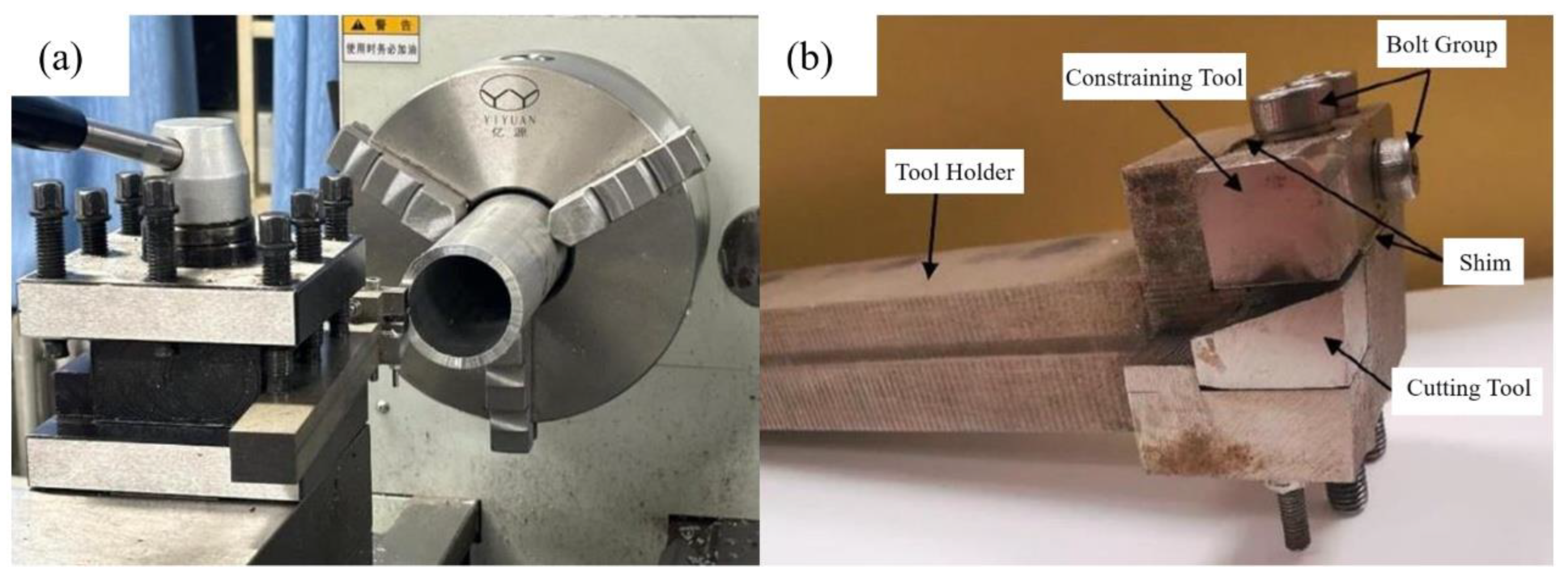
Figure 4.
Average maximum cutting temperatures for different tools.
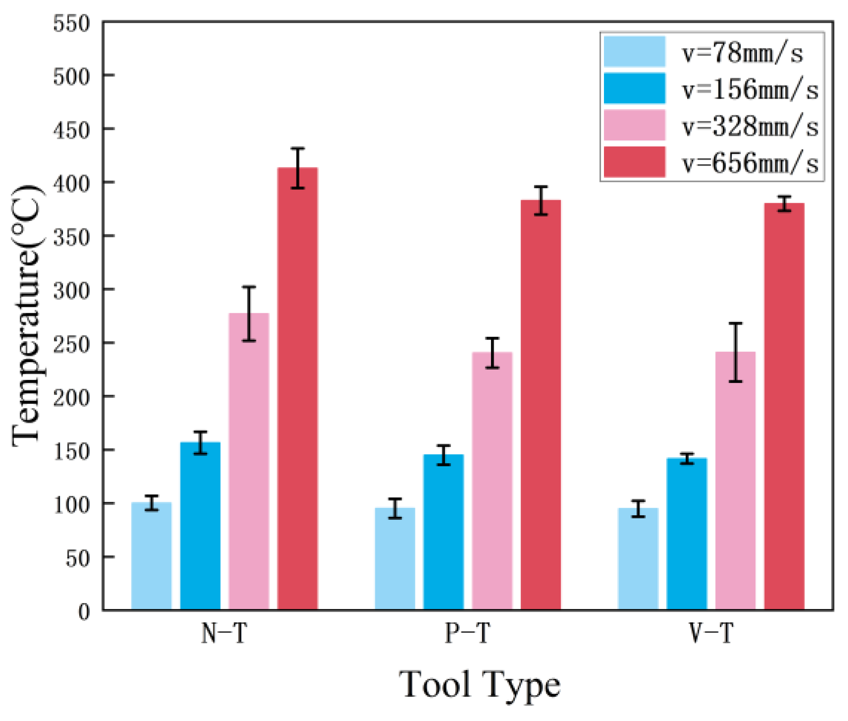
Figure 5.
Microscopic images of chip serration: (a) v=78 mm/s; (b) v=156 mm/s; (c) v=328 mm/s; (d) v=656 mm/s.
Figure 5.
Microscopic images of chip serration: (a) v=78 mm/s; (b) v=156 mm/s; (c) v=328 mm/s; (d) v=656 mm/s.
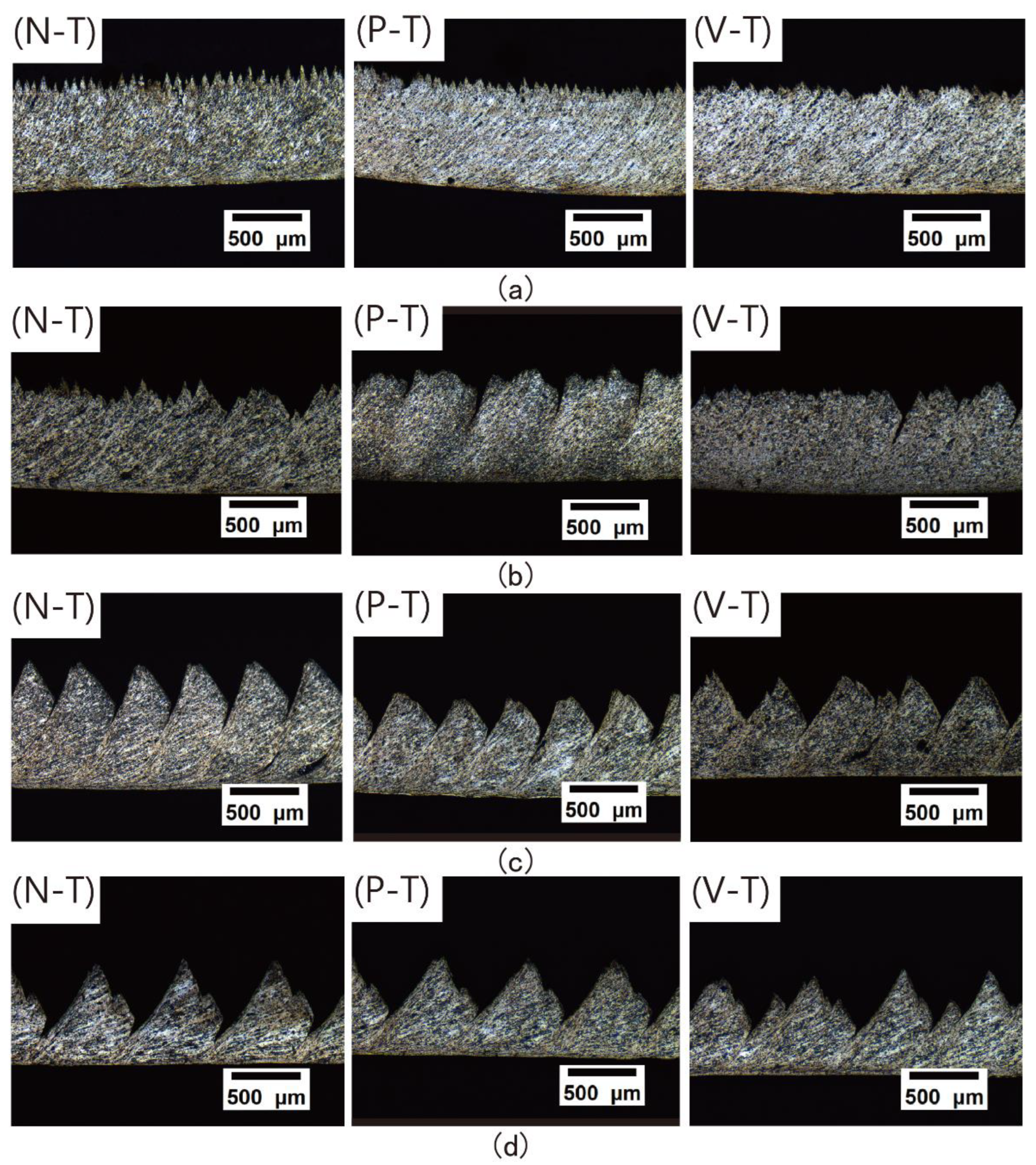
Figure 6.
Chip Serration Parameters Diagram.
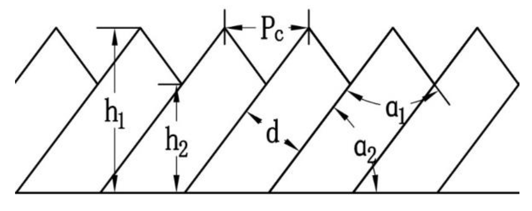
Figure 7.
Chip serration: (a) Serration degree Gs; (b) Tooth-peak spacing Pc.
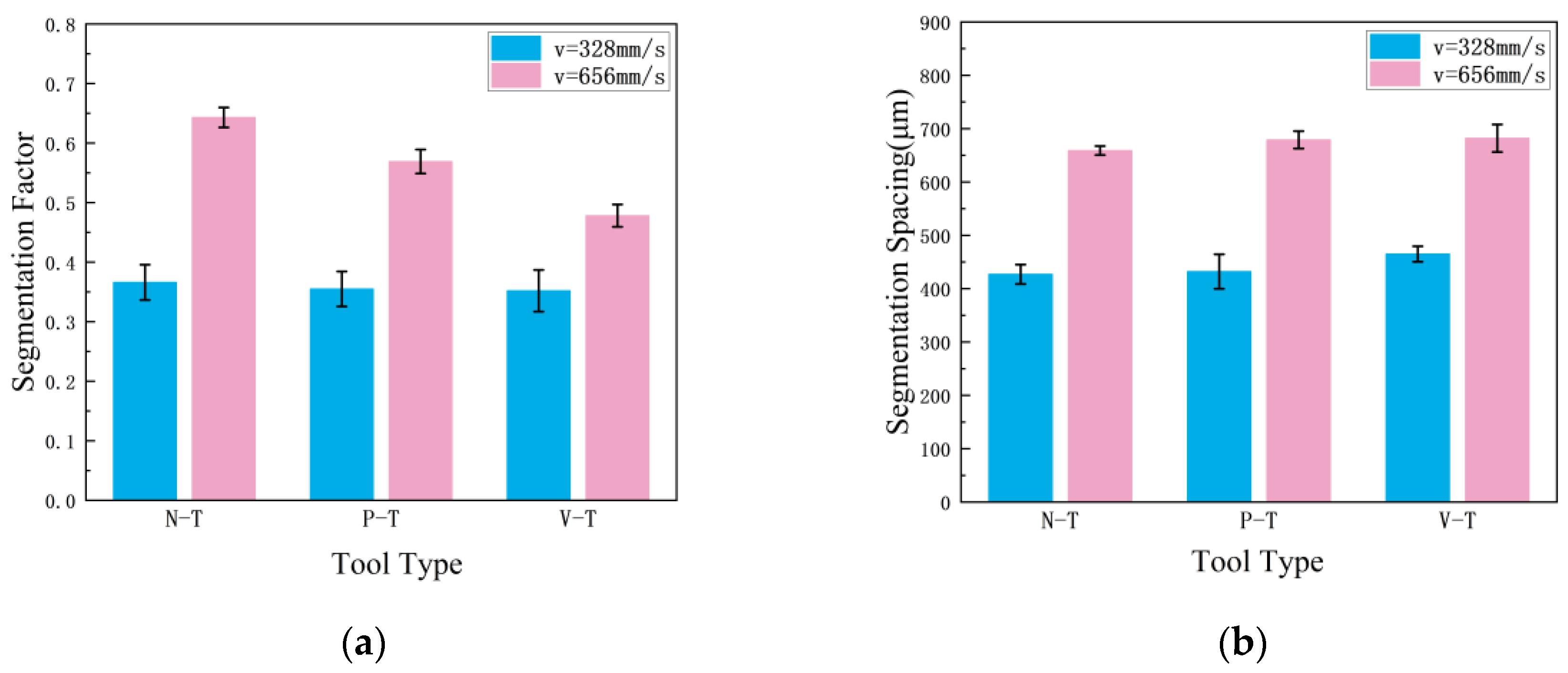
Figure 8.
(a) Metallographic microstructure of serrated chip morphology; (b) Metallographic microstructure of the shear band (ASB).
Figure 8.
(a) Metallographic microstructure of serrated chip morphology; (b) Metallographic microstructure of the shear band (ASB).
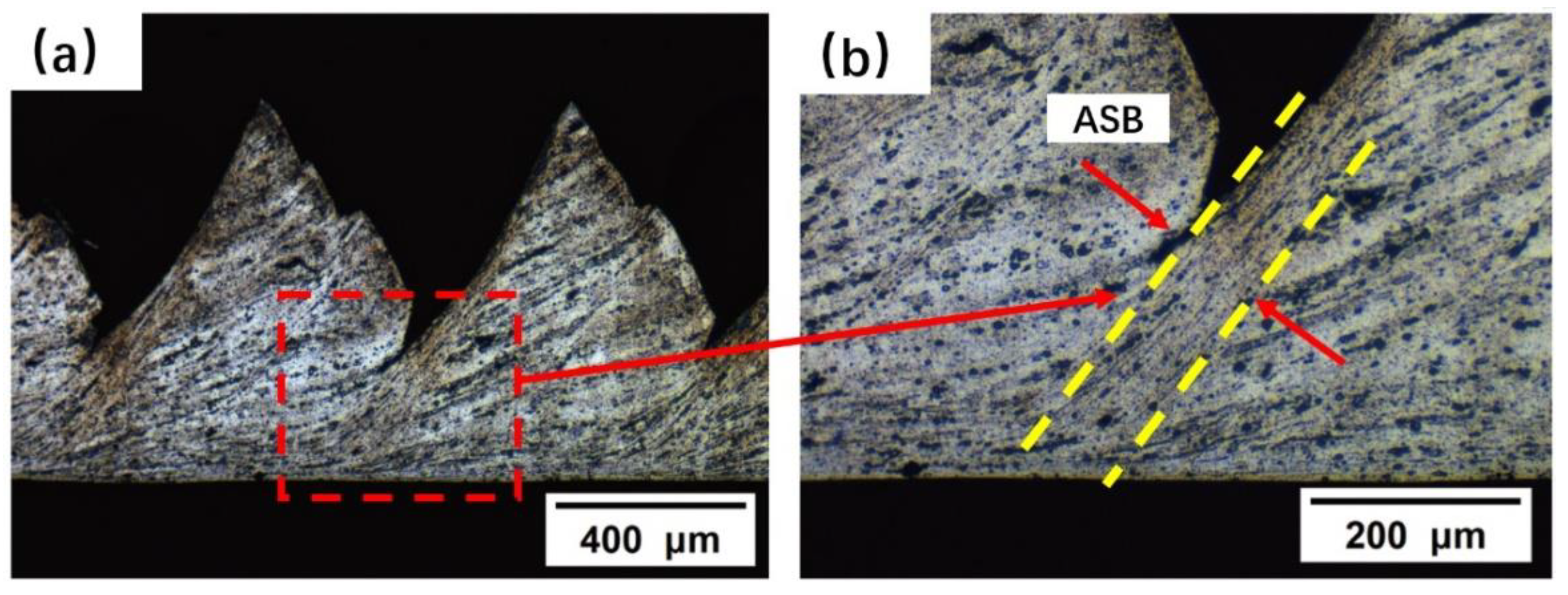
Figure 9.
(a): Hardness of shear slip zone at different cutting speeds; (b): Hardness of matrix zone at different cutting speeds.
Figure 9.
(a): Hardness of shear slip zone at different cutting speeds; (b): Hardness of matrix zone at different cutting speeds.
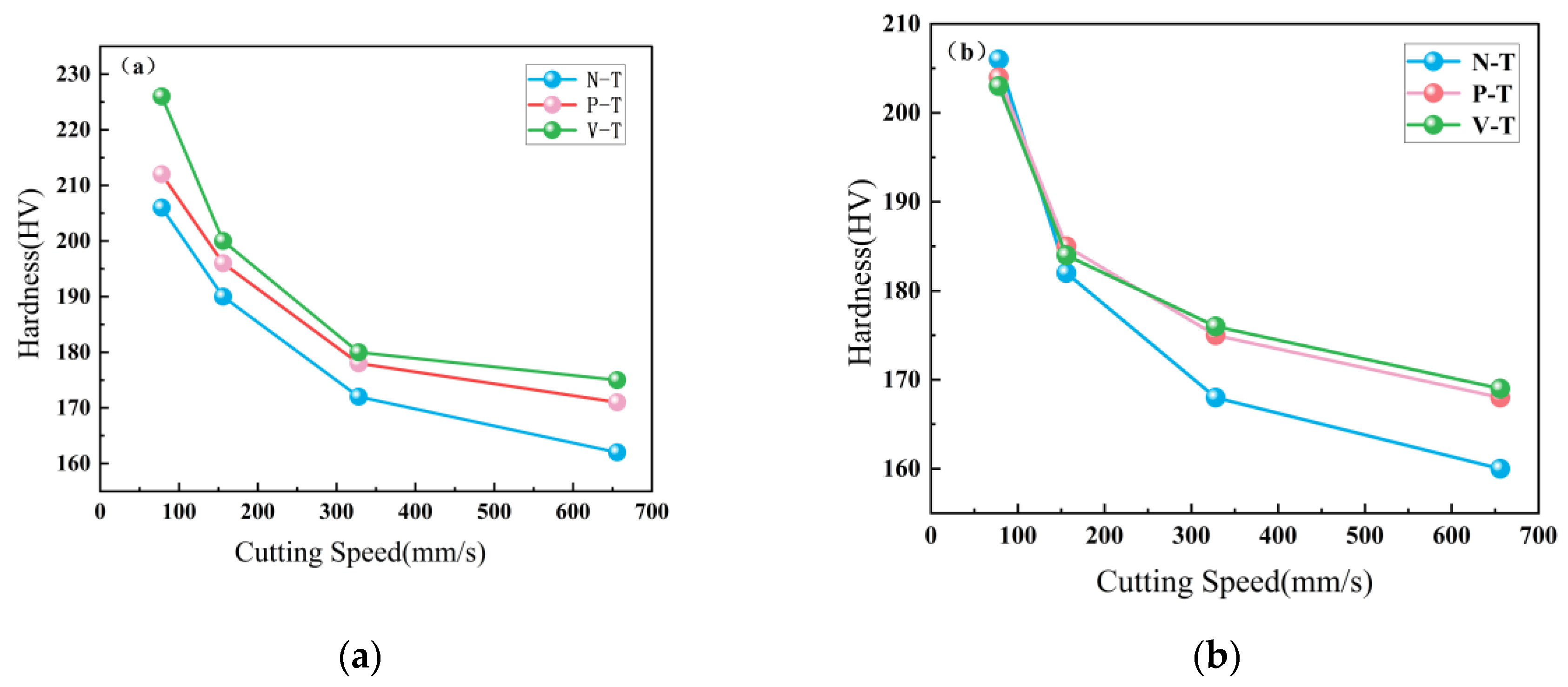
Figure 10.
XRD phase analysis of chip specimens.
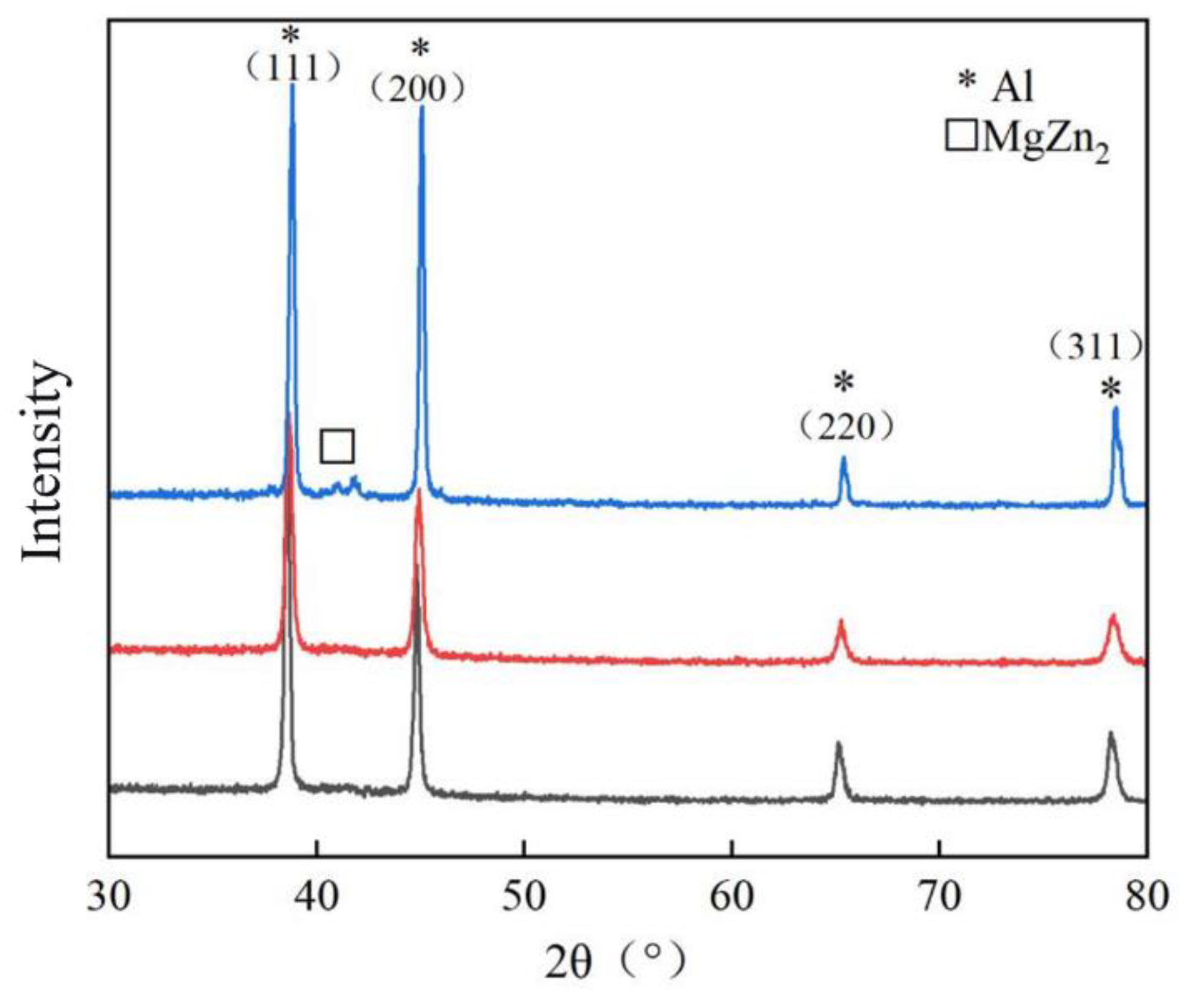
Figure 11.
XRD Diffraction Data Fitting.
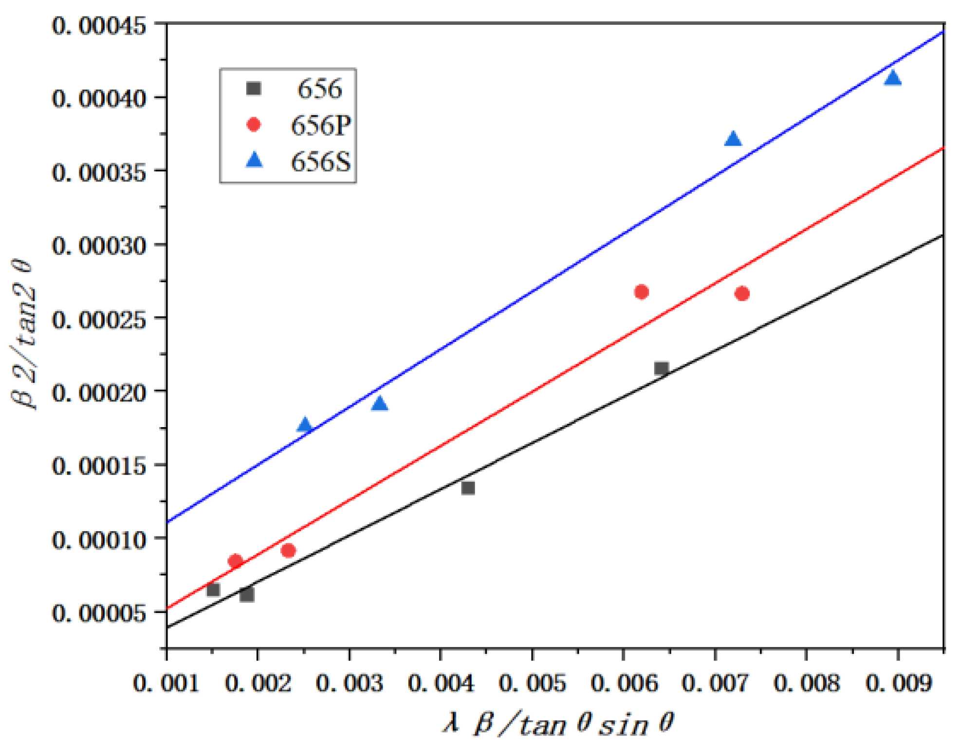

Table 1.
XRD measurement data and calculation results.
| Group |
2θ (deg) |
Full width at half maximum (FWHM) (deg) |
Microstress Deformation (%) |
Grain size Dimension (nm) |
Dislocation Density Density (m-2) |
| N-T | 38.81581 | 0.29614 | 0.202 | 37.3 | 2.68×10¹⁴ |
| 45.0685 | 0.27525 | ||||
| 65.40259 | 0.28876 | ||||
| 78.51829 | 0.37652 | ||||
| P-T | 38.81581 | 0.32271 | 0.258 | 27.8 | 4.42×10¹⁴ |
| 45.0685 | 0.38166 | ||||
| 65.40259 | 0.34757 | ||||
| 78.51829 | 0.42503 | ||||
| V-T | 38.58053 | 0.40723 | 0.168 | 25.6 | 1.01×10¹⁵ |
| 44.83276 | 0.45517 | ||||
| 65.17355 | 0.50584 | ||||
| 78.29915 | 0.61913 |
Disclaimer/Publisher’s Note: The statements, opinions and data contained in all publications are solely those of the individual author(s) and contributor(s) and not of MDPI and/or the editor(s). MDPI and/or the editor(s) disclaim responsibility for any injury to people or property resulting from any ideas, methods, instructions or products referred to in the content. |
© 2025 by the authors. Licensee MDPI, Basel, Switzerland. This article is an open access article distributed under the terms and conditions of the Creative Commons Attribution (CC BY) license (http://creativecommons.org/licenses/by/4.0/).
Copyright: This open access article is published under a Creative Commons CC BY 4.0 license, which permit the free download, distribution, and reuse, provided that the author and preprint are cited in any reuse.


