Submitted:
22 October 2025
Posted:
24 October 2025
You are already at the latest version
Abstract
In this study, a semi-reentrant Miura-origami (SR-MO) inspired auxetic structure, trapezoidal and hexagonal honeycomb configurations, is investigated and extended to a sandwich model using finite element simulation. The SR-MO structure is designed by in-ter-assembling semi-reentrant unit cells into a metamaterial configuration with in-ward-angled edges modifying conventional hexagonal cells, where only one side of each hexagon is inclined inward to form a semi-reentrant geometry. The geometric relation-ships and relative density of the structure are systematically established. A Miura-inspired single unit cell is first introduced, and the unfolding process of the SR-MO structure under compression is analyzed. Finite element method (FEM) simulations demonstrate that the SR-MO metamaterial exhibits superior energy absorption (EA) and specific energy absorption (SEA) characteristics compared to the trapezoidal and hexagonal configurations. Notably, the SR-MO structure shows the highest out-of-plane com-pression resistance and stability, achieving an energy absorption of 80.5% and a specific energy absorption of 80.9%, surpassing other topologies. The peak and plateau forces during in-plane compression are also highest for the SR-MO design, reflecting its enhanced mechanical stability.
These results confirm that the semi-reentrant Miura-origami (SR-MO) configuration pro-vides exceptional potential for applications requiring efficient energy dissipation and structural stability such as light-weight aerospace structures, with energy efficiencies of 89% and 70% for the out-of-plane and in-plane configurations, respectively.
Keywords:
semi-reentrant (SR)
; Miura-origami
; out-of-plane compression
; in-plane compression
; unfolding
; energy absorption
; finite element method
; aerospace structures
1. Introduction
This numerical study proposes a semi-reentrant origami metamaterial, exhibiting high energy absorption and stability under compression. Mechanical metamaterials, engineered materials whose properties are primarily determined by their structural design rather than their constituent materials, have recently attracted significant research attention (Bertoldi et al., 2010; Kadic et al., 2012; Zheng et al., 2014). The intricate structures gain unconventional properties and yield origami-inspired engineering applications, including soft robotics (Rus & Sung, 2018; Tang et al., 2020), self-folding structures (Petras & Sutcliffe, 1999; Rastogi & Kandasubramanian, 2019; Zolfagharian et al., 2018), biomechanical materials (Bukauskas et al., 2021; Koffler et al., 2019) and so on. Among the applications, energy absorbers aim at precluding global buckling and achieving yielding along the entire length by introducing origami patterns as geometrical imperfections.
The energy absorption capabilities of thin-walled structures with varying thicknesses were explored by Sun et al. (Sun et al., 2017). Their research analysed variations in plate thickness along both longitudinal and transverse directions and evaluated the influence on crashworthiness through a combination of numerical simulations and experimental validations. Similarly, Pang et al. (Pang et al., 2019) studied the energy absorption behaviour of variable-thickness thin-walled structures under out-of-plane loading conditions. Besides the thickness of the thin-wall structures.
The structure’s design significantly affects energy absorption, where thicker materials absorb more energy and are higher in stiffness. Shapes like tubes promote controlled folding, while smart features such as grooves and tessellated (Liu et al., 2018) type improve energy efficiency and overall performance (Lv et al., 2023; Niu et al., 2022; Zhong et al., 2025). Furthermore, axial compression tests were conducted on several typical thin-walled designs, including a triangulated foldable cylinder for deployable applications and cylindrical structures consisting of helical strips with triangular panels. The experimental results were validated against computational simulations (Guest & Pellegrino, 1994).
The mechanical behaviour of origami tubes coupled in a zipper arrangement (Filipov et al., 2015) has also attracted research interest due to their distinctive response, where these systems carry loads through tension and compression in the sheet material without exhibiting kinematic deployment motion. Such origami-inspired tubes can be assembled into diverse cellular configurations, leading to enhanced mechanical performance and functional versatility. As origami concepts continue to permeate engineering applications, zipper-coupled tube structures are anticipated to play an important role in enabling deformable systems that retain high structural stiffness (Filipov et al., 2015).
Sandwich panels are essential structures in applications that require absorbing impact or blast energy due to their excellent energy absorption capabilities. In industries like civil engineering, transportation, and aerospace, there’s a rising demand for structures that offer better energy-to-weight ratios to create lightweight designs. In the automotive sector, energy absorbers are commonly used in the form of column-like structures, designed to absorb as much impact energy as possible, helping to minimize the force transferred to the vehicle’s occupants during a crash (Ghanbari & Panirani, 2024). Sandwich panels are made up of two thin, stiff outer layers (face-sheets) on the top and bottom, with a lightweight, thicker core in between. This core adds very little extra weight but significantly boosts the panel’s bending stiffness, resistance to buckling, shear stiffness, and ability to absorb energy (Allen, 2013; Gibson, 2003). The complexity of sandwich panels is increasing due to the need for better structural, aerodynamic, and thermal insulation/heat exchange properties across various engineering applications. Recent studies have shown that enhancing the multifunctional performance of these panels can be achieved by improving the microarchitecture of the cellular core during fabrication (Akbarzadeh et al., 2014). The structural performance and energy absorption capacity of architected sandwich panels are primarily influenced by the material properties and geometric characteristics of the face-sheets and the cellular core. Among various core cell topologies, the hexagonal honeycomb structure is widely used and studied for sandwich panel cores (Buitrago et al., 2010; Petras & Sutcliffe, 1999; Rathbun et al., 2006). Traditionally, auxetic cellular cores have been produced through a complex, multi-step manufacturing process, requiring intricate mould designs and heat compression techniques (Vogiatzis et al., 2017).
In aerospace and automotive applications, sandwich panels with auxetic cores provide enhanced protection against low-energy impacts from small objects (like debris), outperforming conventional cellular core topologies in exterior frame applications.
Due to the auxetic behaviour, auxetic cores reveal unique mechanical properties such as increased indentation resistance (Lakes & Elms, 1993), shear resistance (Vogiatzis et al., 2017), fracture toughness (Yang et al., 2004) (Grima & Evans, 2000) and energy absorption capacity (Evans, 1991) (Mohsenizadeh et al., 2015). The auxeticity of the cellular core of sandwich structures could improve specific mechanical properties, e.g. reduced deflection during flexural bending (Evans, 1991), and make these structures ideal for applications such as sensors and actuators (Evans & Alderson, 2000).
This study addresses the performance of semi-reentrant Miura-origami-inspired, trapezoidal auxetic structures and conventional honeycomb structures under in-plane and out-of-plane configurations. Firstly, we investigated how the enhancement of energy absorption takes place within unit cell configurations, finding that larger unit cells significantly improve energy absorption. Finite element simulations reveal that out-of-plane compression outperforms in-plane configuration in terms of peak force, plateau force, energy absorption (EA), and specific energy absorption (SEA). Additionally, the unit cell was extended to a sandwich structure to enhance crush energy absorption. The study ensures material and structural stability under compressive forces, demonstrating that the Miura-origami lattice provides superior stability by efficiently distributing stress, making it suitable for stable energy dissipation in critical applications.
Semi-reentrant Miura-origami has emerged as an efficient energy-absorbing system, offering deployability through a single flexible motion while becoming significantly stiffer under compression, enhancing energy absorption. This structure holds potential for applications in crash protection within robotics, aerospace, and automotive industries. Additionally, integrating a sandwich structure with Miura-origami further boosts energy absorption. Numerical investigations of both in-plane and out-of-plane compressions are essential to enhance the energy absorption capabilities of the semi-reentrant Miura-origami sandwich structure. The analysis focuses on deformation behaviour, force-displacement response, plateau force, densification displacement, and specific energy absorption, demonstrating superior energy dissipation and a high strength-to-weight ratio compared to traditional metamaterials.
2. Materials and Methods
2.1. Geometric Definition
In this section, the geometric design concepts of the conventional honeycomb, the semi-re-entrant Miura origami-inspired and trapezoidal unit cells are illustrated in Figure 1(a-c). The highlighted arrows indicate the geometric modifications applied during the patterning process from
In this section, the geometric design concepts of the conventional honeycomb, the semi-re-entrant Miura origami-inspired and trapezoidal unit cells are illustrated in Figure 1(a-c). The highlighted arrows indicate the geometric modifications applied during the patterning process from Figure 1(a) to Figure 1 (b), where the top, bottom, and side ligaments were adjusted to obtain the desired lattice configurations. Specifically, in the semi-re-entrant design Figure 1 (b), the right-side ligament edges were inclined inward, forming the re-entrant angles responsible for the auxetic behaviour under in-plane deformation and Figure 1(c) represents a trapezoidal corrugated unit cell.
2.2. Curved Miura Origami and Hexagonal Unit Cell Design
Figure 2 (a-d) shows the overall design of the hexagonal (non-auxetic), re-entrant (partial re-entrant) semi-reentrant Miura-origami-inspired and trapezoidal structure. A semi-reentrant Miura-origami cell consists of six equivalent panels connected to create one-unit cells, defined by a height h, width l, depth d, and angle θ in Figure 2 (d-f). For our numerical simulation setup, we depend on a cell with l = h = 5 and angle θ = 120° as the basis for all structures unless otherwise noted. The dimensions of the sandwich panel, including length (a), width (b), and total thickness (h), are shown in Figure 2(e). A 2D schematic representation of the semi-reentrant is presented in Figure 2(h).
The beam’s geometry suggests that the folding behaviour is driven by an external load that induces a change in angle. Figure 2 (i & j) seems to depict the kinematic representations and deformations of the unit cell of the lattice structure. The 1D in Figure 2(h) shows the angular displacement (240°), representing the rotation of the unit cell due to the applied forces, with variables such as ∆Φ indicating changes in angle and shape. Panel (j) illustrates the relative displacement of the structure, where Δh and ΔΦ denote changes in height and angle, respectively. This depicts how the cellular core deforms, potentially through bending, in response to external forces. These kinematic representations are crucial for understanding how the lattice structure behaves under load and its deformation mechanisms.
On the left side, the beam is shown in its folded state, with an angle ϕ0 denoting the initial angular displacement between the connected segments of the structure. The geometric relations of these structures were accurately calculated, and their relative density was also established in Eqn. (1).
Where l inclined arm length h vertical arm height t, 2t cell wall thickness d thickness of structure/depth α, β, angles between arms, t = 1 mm α = β = 〖30〗^0. The design enables efficient material utilization, facilitating compact deformation and making it suitable for applications such as deployable structures or energy absorption systems.

Table 1.
Miura-Origami lattice cell structure design parameter dimensions (in mm).
| Structures | h | l | d | tp | Angle () |
| Miura/Hexagonal/trapezoidal | 5 | 5 | 5 | 1 | 1200 |
| Sandwich | 100 | 100 | 40 | 1 | 1200 |
2.3. Energy Absorption Criteria
To assess the structures’ performance in energy absorption applications, the criteria defined in the following are commonly used in the literature.
Energy absorption (EA): the total energy absorbed by the structure under impact or crushing loads. It can be calculated by integrating the load-displacement curve as,
Where () is the compressive load, a function of the displacement of the point it is applied to, and is the maximum effective deformation.
Specific Energy Absorption (SEA): The EA is not so good in comparing the performance of the structures for energy absorption applications since the total absorbed energy varies with the mass of the structure. So, the SEA is defined as the absorbed energy per unit mass of the structure, as,
Where m is the total mass of the structure, since energy absorption efficiency (η) is another parameter to identify the optimal energy absorption, it needs to be considered; the energy absorption efficiency is given according to Eqn (4).
2.4. Finite Element Modelling
Numerical finite element simulations of compression were conducted using Abaqus/Explicit, a dynamic solver for nonlinear problems involving large deformations and contact. The structure was placed on a stationary rigid plate, and a moving plate applied a prescribed displacement to simulate 75% height compression. The rigid plate was fully fixed, with a smooth amplitude function controlling the displacement. A 0.5mm mesh of four-node shell elements (S4R) with reduced integration was used. Self-contact simulated internal interactions, and surface-to-surface contact with a friction coefficient of 0.3 modelled interactions with the rigid plates. The goal was to design an energy-absorbing structure utilizing ABS’s energy-dissipating properties. The stress-strain curve of ABS data is assumed elasto-perfectly plastic model for FEM analysis, summarized in Table 2.
2.5. Validation on Finite Element Modelling
To verify the accuracy of the models, semi-re-entrant Miura, hexagonal and trapezoidal lattices, FEM with the number of 5 × 5-unit cell is constructed. As presented in Figure 3, the lower rigid wall is fully constrained, and the five degrees of freedom of the upper rigid wall, except for the movement along the z-axis, are restricted. Quasi-static axial compression load is applied on the upper rigid wall of the FEM. The general contact algorithm is utilized to define global interaction of the FEM, including “hard” contact of normal behaviour and tangential behaviour with a friction coefficient of 0.3 to avoid mutual penetrations among adjacent components. Topological parameters of FEM are listed in Table 1.
3. Results and Discussion
Figure 4 (a) presents the force versus displacement curves for Miura-origami-inspired auxetic lattice structures, which are modelled using shell element metamaterials. The simulations were conducted with constant mass for the unit cell configurations: 2 x 2, 3 x 3, 4 x 4, and 5 x 5. Each configuration represents a different number of unit cells, and a constant mass approach across all configurations was accounted for to ensure the vitality of normalized energy absorption by mass for more accurate assessments of the structure’s performance. The Figure 4 curves show the mechanical response of the lattice structures under compression, highlighting the relationship between applied force and displacement during the deformation process.
The results for energy absorption, densified displacement, and specific energy absorption characteristics, all with a constant shell thickness and mass, are presented in Table 3. These values highlight the performance variations across different unit cell configurations.
As shown in Table 3, the results demonstrate a significant influence of unit cell number on the EA. The specific energy absorption varied notably with the increase in unit cell number, indicating that a higher number of unit cells leads to changes in the overall deformation and energy dissipation behaviour. This behaviour can be attributed to the increased complexity in the interactions between unit cells, especially as the lattice structure undergoes compression. As the number of unit cells grows, the overall stiffness, flexibility, and energy absorption capacity of the structure are altered due to the redistribution of forces within the lattice configuration. The findings suggest that careful tuning of the unit cell number can enhance the energy absorption characteristics, making it possible to design more efficient structures for applications requiring high energy dissipation.
Figure 5 (a-d) illustrates the deformation behaviour of a Miura origami-inspired structure under applied load, with a focus on the von Mises stress distribution. Figure 5 (a & b), the 2 x 2 & 3 x 3 configurations show relatively low von Mises stress across the structure, indicating minimal strain and relatively uniform stress distribution during deformation, respectively. As the configuration is increased to 4 x 4 in Figure 5(c), the stress distribution becomes more concentrated, with higher stress values observed at the edges and within the folds, signifying localised deformation as the structure begins to absorb the applied load more significantly. Figure 5 (d) depicts the 5 x 5 configuration, where the deformation is more pronounced, and the von Mises stress is further elevated, especially in the areas of higher strain within the origami folds. This indicates the increased structural response to higher load application, highlighting the relationship between the size of the structure and the distribution of stress.
Figure 6 Show the energy absorption and specific energy absorption of semi-re-entrant miura origami-inspired auxetic lattice structures with varying lattice configurations under compression. Figure 6 (a), the total energy absorption is plotted against displacement for different configurations: 2 x 2, 3 x 3, 4 x 4, and 5 x 5. As the lattice size increases, the total energy absorption increases significantly, with the 5 x 5 configuration exhibiting the highest energy absorption at larger displacements. The 2 x 2 configuration shows the lowest energy absorption, while the 3 x 3 and 4 x 4 configurations provide intermediate results. This trend demonstrates that larger configurations, with more unit cells, are more effective at absorbing energy under compression. In the same way, Figure 5 (b) shows the specific energy absorption (SEA), calculated as the energy absorbed per unit mass of the structure, and plotted against displacement for the same configurations. Figure 6 (c), the total energy absorption increases with the lattice size, with the 2 x 2 configuration absorbing 1.75877 kJ, the 3 x 3 absorbing 2.37901 kJ, the 4 x 4 absorbing 2.77029 kJ, and the 5 x 5 absorbing 3.31438 kJ. This trend indicates that larger configurations can absorb more energy under the same loading conditions. Figure 6 (d) shows the specific energy absorption with normalized mass, where the 2 x 2 configuration has a value of 13.32 kJ/kg, and the SEA increases as the lattice size increases, reaching 25.25 kJ/kg for the 5 x 5 configuration. The increase in SEA with lattice size demonstrates the enhanced efficiency of energy absorption in larger configurations, making them more effective for applications requiring high energy dissipation per unit mass. These results highlight the importance of lattice configuration in enhancing both total and specific energy absorption in Miura origami-inspired structures.
The SEA curves suggest that while larger configurations absorb more energy overall, they also become more efficient in terms of energy absorption per unit mass, making the 5 x 5 configuration particularly advantageous for applications requiring high energy dissipation with low mass.
In many materials, the energy absorbed during the plateau phase is often modelled as the product of the plateau force and the displacement range over which the material undergoes deformation. A linear relationship between plateau force and displacement during the plastic deformation phase suggests that the energy absorption mechanism in the material or lattice structure is primarily governed by plateau force, as displayed in plateau force vs displacement in Figure 6(e). An average plateau force () of lattice structures can be calculated as follows in Eqn (6).
where δy denotes the initial yielding compression displacement and is typically negligible in the expression.
As shown in Figure 6(f), the comparison between the conventional hexagonal honeycomb and the Miura-origami-inspired auxetic lattice indicates that the conventional hexagonal configuration exhibits superior mechanical performance at the unit-cell level. Compared with the Miura-5×5 structure, the Hex-5×5 configuration demonstrated approximately 111.8% higher values in both stiffness and energy absorption. This substantial increase highlights the superior mechanical efficiency of the hexagonal geometry, which provides improved load-bearing capability and deformation stability, contributing to enhanced structural performance under compressive loading conditions, as per Eqn. (5). The Trap-5 x 5 structure absorbed 31.16% of the total energy but contributed only 10.17% to the total SEA, revealing significantly lower mass-efficient energy absorption. The Miu-5 x 5 structure demonstrated a balanced contribution, representing 22.08% of the total EA and 28.81% of the total SEA.
The hexagonal structure demonstrates higher energy absorption (EA) and specific energy ab-sorption (SEA) across the displacement range compared to the semi-re-entrant Miura and trapezoidal structure, as shown in Table 3. The hexagonal 5x5 configuration consistently absorbs more energy due to its extensive deformation and efficient energy dissipation mechanism. This makes it ideal for applications requiring high energy absorption. However, Figure 7(b & d) reveals slightly localized von Mises stresses in the hexagonal structure, especially around the fold lines and vertices of the cells. While this allows for greater energy absorption, it may lead to material failure under extreme loading. The stress concentration in the hexagonal design could limit its practical use unless materials are designed to handle such stresses. In contrast, the Miura origami configuration shows more uniform stress distribution, Figure 7 (a). The progressive unfolding mechanism of Miura origami leads to a more evenly distributed stress profile, which results in less risk of material failure under impact loads. This characteristic makes the Miura design a more stable choice for applications where maintaining lower stresses is a priority.
3.1. Sandwich Semi-Re-Entrant Miura-Origami Structure Under Loading
The semi-re-entrant Miura-origami inspired auxetic lattice sandwich panel, as depicted in Figure 1(e), is characterised by the following dimensional parameters: length (a), width (b), and total thickness (h), with the coordinate system (x, y, z) defined at the mid-plane of the panel. The specific dimensions employed in this study are provided in Table 1. The core of the sandwich panel is composed of six-sided cells, which are based on Miura-origami-inspired auxetic structures, and these cells serve as the cellular core within the sandwich configuration.
To investigate the effect of topology and relative density of cellular core on the energy absorption capability of the architected sandwich panel, while maintaining total dimensions constant, for programmable cells: the angle between the cell wall, Θ, and the number of unit cells in the out-of-plane direction of the core, a and the number of unit cells in the in-plane direction, b. The number of unit cells in the out-of-plane and in-plane directions is selected to fill the panel’s global dimensions (a & b). The constraint of > 100° has been imposed based on the wall thickness to prevent the overlap of the cell walls and to keep the structural integrity during downward compression.
The sandwich structure for energy absorption was investigated in both out-of-plane and in-plane modes. To prevent deformation, rigid top and bottom platens were used in the simulation (see Figure 8). The bottom platen was fully constrained in all six degrees of freedom (three translations and three rotations), while the top platen was allowed to move downward along the Z-axis. To reduce computational cost without compromising accuracy, the loading velocity was set to 625 mm/s, as compressive velocities below this value have been shown to have negligible effects on the results in previous studies. Moreover, the chosen velocity ensured that the amount of kinetic energy compared to the internal energy is insignificant.
3.2. Deformation Patterns
The in-plane and out-of-plane performances of the semi-reentrant Miura-origami were numerically examined. The deformation pattern (isometric, side and right views) of the compressed material at axial displacements of 5.8 mm and 10.3 mm is shown in Figure 9 (a-b), respectively, for in-plane. At a small axial displacement (5.8 mm), the stress initiates at the Miura origami specimen’s distal ends (top and bottom). Afterwards, the middle of the deformed cells at the centre of the specimen starts folding inside toward the centre of the compressed specimen. It is evident that at 5.8 mm axial displacement, the stress spreads along the loading (Z) direction. During compression, the overlapping unit cell line contributes as a stiffener. It is evident that the deformations of the cells toward the center region initiated from the bottom and top, ensuring that the boundary conditions are compatible during compression and inward lateral compressions and leading to in-crease in the resistance of the compressed specimen.
Meanwhile, on the same way, the out-of-plane performances of the semi-reentrant Miura-origami were numerically examined. The deformation pattern (isometric, side and right views) of the compressed material at axial displacements of 5.8 mm and 10.3 mm are shown in Figure 10 (a-b), respectively. At a small axial displacement (5.8 mm), the stress initiates at the Miura origami specimen’s distal ends (top and bottom). Afterwards, the middle of the deformed cells at the centre of the specimen folded inside toward the centre of the com-pressed specimen. It is evident that at 3 mm axial displacement, the stress spreads along the loading (Z) direction. During compression, the valley line contributes as a stiffener. The deformations of the cells toward the center region are initiated from the bottom and top, ensuring that the boundary conditions are compatible during compression and outward expansions are taking place during compressions and leading to an increase in the resistance of the compressed specimen. The deformation pattern of the semi-reentrant Miura origami inspired specimen at large axial displacement up to 10.3mm is shown in Figure 9.
Figure 10 (c-d) displays the deformed side views associated with out-of-plane deformation under compressive loading. In contrast, Figure 10 (e-f) presents the left and right lateral perspectives of the deformation, highlighting structural responses and failure patterns resulting from directional load application on the cellular core architecture.
In the same way, the out-of-plane performances of the trapezoidal sandwich were numerically examined. The deformation pattern (isometric, side and right views) of the compressed material at axial displacements of 5.8 mm and 10.3 mm is shown in Figure 11 (a-b), respectively. At a small axial displacement (5.8 mm), the stress initiates at the trapezoidal specimen’s distal ends (top and bottom). Afterwards, the middle of the deformed cells at the centre of the specimen folded inside toward the centre of the compressed specimen. It is evident that at 3 mm axial displacement, the stress spreads along the loading (Z) direction. During compression, the valley line contributes as a stiffener. The deformations of the cells toward the centre region are initiated from the bottom and top, ensuring that the boundary conditions are compatible during compression and outward expansions are taking place during compressions and leading to an increase in the resistance of the compressed specimen. The deformation pattern of the trapezoidal specimen at large axial displacement up to 10.3mm is shown in Figure 11.
Figure 11(c-d) displays the deformed side views associated with out-of-plane deformation under compressive loading. In contrast, Figure 11 (e-f) presents the left and right lateral perspectives of the deformation, highlighting structural responses and failure patterns resulting from directional load application on the cellular core architecture. Figure 12 (a-f) also shows the in-plane deformation process for the trapezoidal sandwich structure.
Figure 13 (a-b) shows force-displacement curves for in-plane and out-of-plane compression of a semi-reentrant Miura-origami structure, highlighting key differences in structural be-haviour under load. Both figures exhibit similar trends, beginning with zero force at zero dis-placement, indicating no resistance initially. As the displacement increases, the force rises sharply, reaching a peak force (yield point) where the material transitions from elastic to plastic deformation, characterized by a significant curve flattening. Figure 13 (a) shows the force plateaus around 250 kN for out-of-plane compression, showing sustained energy absorption after yielding. In contrast, the in-plane compression Figure 13(b) peaks at a lower 60 kN, with a notable steep rise followed by a sudden increase after a plateau, suggesting further deformation or failure. The out-of-plane compression absorbs more energy, likely due to more uniform material deformation, while the in-plane compression shows localized deformations, resulting in lower force absorption. Both tests demonstrate significant plastic deformation post-yield, but the out-of-plane configuration yields higher energy absorption, indicating a more efficient compressive response.
The deformation of the semi-reentrant Miura-origami inspired by large axial displacements in Figure 14 (a-c) is similar to that described previously and shown in Figure 9. However, in the case of the compressed semi-reentrant Miura origami-inspired, global buckling occurred in the middle of the length along the Z direction, in-plane to the length. With the progression of the deformation, the specimens localized in the middle. Such behaviour might lead to an increase in the compressive stress but reduce the compressibility.
The deformation of the Miura origami at large axial displacements, see Figure 14 (d-f). However, the compressed Miura origami experienced global buckling in the middle of the length along the Z direction (out-of-plane length). With the progression of the deformation, the specimens localised in the middle. Such behaviour might lead to an increase in the compressive stress but reduce the compressibility.
Figure 15 illustrates the energy absorption (EA) and specific energy absorption (SEA) of semi-re-entrant Miura origami-inspired structures with different configurations, comparing in-plane and out-of-plane deformation modes. Figure 15 (a) shows the total energy absorption as a function of displacement, where the out-of-plane mode exhibits much higher energy absorption, especially at larger displacements (20 mm), indicating its superior energy dissipation under compression. Figure 15 (b) displays SEA on a logarithmic scale, showing that the in-plane mode absorbs more energy per unit mass at lower displacements, while the out-of-plane configuration becomes significantly more efficient at higher displacements. Figure 15 (c) presents EA in a bar chart format, reinforcing the higher energy absorption of the out-of-plane configuration. Figure 15 (d) highlights SEA, where the out-of-plane mode becomes increasingly efficient with displacement. These results demonstrate that while in-plane deformation is more efficient at small displacements, out-of-plane deformation is far superior for larger displacements, making it ideal for applications requiring high energy dissipation, such as impact-resistant structures.
Figure 16 presents a comparison of architected sandwich panels with alternative cellular core architectures, focusing on two cell types, out-of-plane and in-plane. For both cell types, the mass is consistent at 0.366 kg. The energy absorption (EA) values for out-of-plane and in-plane cells are 422.01 kJ and 2215.815 kJ for the hexagonal cell core structure, and 971.593 kJ and 128.656 kJ for the Miura-origami, respectively. The specific energy absorption (SEA) values are significantly different, with the out-of-plane cell at 1.153 mJ/kg and the in-plane cell at 6.054 mJ/kg for the hexagonal core cell structure, and 2.655mJ in out-of-plane and 0.352mJ in in-plane for the Miura-origami core cell structure. Additionally, the relative density change (Δr) is identical for both cell types, at 0.34. This data highlights significant differences in energy absorption characteristics between the two core architectures, with the out-of-plane configuration exhibiting higher performance in both EA and SEA. Here, the in-plane hexagonal lattice exhibits higher specific energy absorption (SEA) because its aligned cell walls enable efficient load transfer and stable progressive collapse. In contrast, the semi-re-entrant lattice dissipates less energy due to rotational deformation and early local buckling.
3.3. Effects of Shell Thickness on 5 x 5-Unit Cells for Se-Re-Entrant Inspired Miura, Conventional Honeycomb and Trapezoidal Unit Cells
To examine the influence of unit cell number and shell thickness on the compressive response, simulations were conducted for shell thicknesses of 1.0, 1.5, 2.0, and 2.5 mm across three structural configurations: semi-re-entrant Miura-inspired, conventional honeycomb, and trapezoidal lattices. As illustrated in Figure 17 (a–c), variations in shell thickness significantly affect the force–displacement behaviour of all structures, indicating a strong dependence on geometric stiffness. Furthermore, Figure 18 (a–b) presents the corresponding energy absorption (EA) and specific energy absorption (SEA) performances. The trapezoidal structure exhibits the highest SEA, attributed to its progressive densification and stable deformation mode, while the conventional honeycomb achieves superior total EA due to its uniform load-bearing capacity. In contrast, the semi-re-entrant Miura-inspired structure demonstrates relatively lower SEA and EA values, likely resulting from its localised deformation and negative Poisson’s ratio-induced lateral contraction.
3.4. Application and Prospect
Various scientific studies have revealed that additive manufacturing techniques can be utilized in numerous biomedical, sports, and lightweight structures with internal damping for aero-space and crash protection applications. In the automobile industry, the significance of multi-stiffness metamaterials is substantial. Crash boxes were engineered to absorb impact energy during collisions. The variable stiffness property of metamaterials facilitates a more progressive and controlled collapse, enhancing occupant protection by ensuring the efficient absorption of crash energy. Another potential application is in the sports industry, specifically in helmet design. Helmets must protect the head from varying levels of impact during collisions. Multimaterial design metamaterials can adapt their stiffness to effectively absorb both low- and high-energy impacts. Indeed, helmets incorporating curved re-entrant metamaterials can distribute stresses arising from impact more effectively, reduce strain on the neck, and enhance cycling safety. Generally, multi-material structures such as auxetic foams and curvy-ligament honeycomb auxetic structures are employed in sports equipment, including cricket pads, sports helmets, shin pads, crash helmets, and personal protection equipment, owing to their superior energy-absorbing capabilities under compression.
A study presented in this paper exhibits excellent energy absorption under axial impacts, making it suitable for a variety of applications. Figure 19 (a-f) illustrates potential application scenarios, for a sitting cushion, helmet design for injury protection, car dashboard (air bag) and frontal plane nose for impact protection and vibration control of plane fluttering (wings). These applications benefit from the excellent EA properties of the HC-REC structures, providing enhanced protection against impacts in various directions. When impacted, these HC-REC structures can effectively protect the primary structure’s safety through deformation, absorbing the impact energy and mitigating damage. The choice of materials is crucial considering specific application scenarios, and this will be considered in subsequent work. Although semi-re-entrant Miura-inspired, hexagonal and trapezoidal structures have superior energy absorption properties.
4. Conclusions
In this study, semi-reentrant Miura origami (SR-MO), trapezoidal and hexagonal honeycomb structures were designed. The out-of-plane and in-plane compression in two directions of those structures was investigated and compared. The main conclusions are summarized as follows:
- ➢
- The out-of-plane compression of SR-Miura exhibited a distinct deformation pattern, where SR deformed initially from the top and bottom sections, see Figure 9 (d). The plateau forces for the SR-Miura origami-inspired sandwich structure was calculated as 22.7 kN for out-of-plane and 11.2 kN for in-plane compression. The densification displacement was larger for SR, suggesting that greater compression resistance or plateau force could be attributed to the increased interaction areas between SR and the rectangular structures. The specific energy absorption (SEA) of SR-miura was the highest in the sandwich structure.
- ➢
- During in-plane compression in the z-direction, SR initially deformed at the top and bottom sections, with the middle section remaining stable. Major deformation occurred on the top layers, while the bottom part remained stable, showing slight deformation. The top layer compressed into a triangular shape after substantial loading, while the bottom layers remained stable due to overlapping unit cell stability. The peak and plateau forces of the structures were ranked as follows: out-of-plane SR-miura greater than in-plane SR-miura. The out-of-plane SR exhibited the largest plateau force, energy absorption, and specific energy absorption, while the in-plane RE had the lowest. The sandwich panel with an in-plane honeycomb core demonstrated a prolonged and stable plateau stage, as seen in Figure 8 (b). SR showed an 80.95% and 80.5% improvement in energy absorption for out-of-plane and in-plane compression, respectively, with energy efficiencies of 89% and 70%.
- ➢
- The hexagonal structure exhibits superior energy absorption under in-plane loading but demonstrates reduced performance in the out-of-plane direction due to ligament instability, as highlighted in Figure 1 (a). In contrast, the Miura-origami-inspired design provides improved structural stability and stress distribution efficiency, offering greater out-of-plane stiffness and energy absorption, though with lower in-plane performance attributed to the inward-angled ligaments. Furthermore, the presence of a near-zero Poisson’s ratio enhances buffering and energy dissipation, making the semi-re-entrant Miura origami structure particularly suitable for dynamic loading applications. A more detailed investigation of this behaviour will be conducted in future studies.
Author Contributions
Conceptualisation, M.D., W.A. and T.T.; methodology, M.D., W.A. and T.T.; software, M.D., W.A. and T.T.; validation, M.D., W.A. and T.T.; formal analysis, M.D.; investigation, M.D., W.A. and T.T.; resources, M.D., W.A. and T.T.; data curation, M.D.; writing—original draft preparation, M.D.; writing—review and editing, M.D., W.A. and T.T.; visualisation, M.D., W.A. and T.T.; supervision, W.A. All authors have read and agreed to the published version of the manuscript.
Funding
This research received no external funding.
Data Availability Statement
The raw data supporting the conclusions of this article will be made available by the authors on request.
Conflicts of Interest
The authors declare no conflicts of interest.
References
- Akbarzadeh, A., Fu, J., Chen, Z., & Qian, L. (2014). Dynamic eigenstrain behavior of magnetoelastic functionally graded cellular cylinders. Composite Structures, 116, 404-413. [CrossRef]
- Allen, H. G. (2013). Analysis and design of structural sandwich panels: the commonwealth and international library: structures and solid body mechanics division. Elsevier.
- Bertoldi, K., Reis, P. M., Willshaw, S., & Mullin, T. (2010). Negative Poisson’s ratio behavior induced by an elastic instability. Advanced materials. https://doi.org/https://scholar.harvard.edu/sites/scholar.harvard.edu/files/bertoldi/files/adv-mat-2010.pdf.
- Buitrago, B. L., Santiuste, C., Sánchez-Sáez, S., Barbero, E., & Navarro, C. (2010). Modelling of composite sandwich structures with honeycomb core subjected to high-velocity impact. Composite Structures, 92(9), 2090-2096. [CrossRef]
- Bukauskas, A., Koronaki, A., Lee, T.-U., Ott, D., Al Asali, M. W., Jalia, A., Bashford, T., Gatóo, A., Newman, J., & Gattas, J. M. (2021). Curved-crease origami face shields for infection control. PLoS ONE. 2021; 16(2): e0245737. [CrossRef]
- Etemadi, E., Zamani, A. M. M., Scarpa, F., Zeeshan, M., Hosseinabadi, M., & Hu, H. (2024). Modified re-entrant auxetic metamaterials with energy absorption enhancement. Materials Today Communications, 38, 108079. [CrossRef]
- Evans, K. E. (1991). Auxetic polymers: a new range of materials. Endeavour, 15(4), 170-174. [CrossRef]
- Evans, K. E., & Alderson, A. (2000). Auxetic materials: functional materials and structures from lateral thinking! Advanced materials, 12(9), 617-628. [CrossRef]
- Filipov, E. T., Tachi, T., & Paulino, G. H. (2015). Origami tubes assembled into stiff, yet reconfigurable structures and metamaterials. Proceedings of the National Academy of Sciences, 112(40), 12321-12326.
- Ghanbari, J., & Panirani, P. N. (2024). A hybrid bio-inspired sandwich structures for high strain rate energy absorption applications. Scientific Reports, 14(1), 2865. [CrossRef]
- Gibson, L. J. (2003). Cellular solids. Mrs Bulletin, 28(4), 270-274.
- Grima, J. N., & Evans, K. E. (2000). Auxetic behavior from rotating squares. Journal of materials science letters, 19, 1563-1565. https://doi.org/https://jngrima.com/wp-content/uploads/2017/11/grima-evans-2000-auxetic-behavior-from-rotating-squares.pdf.
- Guest, S. D., & Pellegrino, S. (1994). The folding of triangulated cylinders, Part I: Geometric considerations. [CrossRef]
- Kadic, M., Bückmann, T., Stenger, N., Thiel, M., & Wegener, M. (2012). On the practicability of pentamode mechanical metamaterials. Applied Physics Letters, 100(19). [CrossRef]
- Koffler, J., Zhu, W., Qu, X., Platoshyn, O., Dulin, J. N., Brock, J., Graham, L., Lu, P., Sakamoto, J., & Marsala, M. (2019). Biomimetic 3D-printed scaffolds for spinal cord injury repair. Nature medicine, 25(2), 263-269. [CrossRef]
- Lakes, R., & Elms, K. (1993). Indentability of conventional and negative Poisson’s ratio foams. Journal of Composite Materials, 27(12), 1193-1202. [CrossRef]
- Liu, Y., Zhang, W., Zhang, F., Lan, X., Leng, J., Liu, S., Jia, X., Cotton, C., Sun, B., Gu, B., & Chou, T.-W. (2018). Shape memory behavior and recovery force of 4D printed laminated Miura-origami structures subjected to compressive loading. Composites Part B: Engineering, 153, 233-242. [CrossRef]
- Lv, J., Bai, Z., Du, X., Zhu, F., Chou, C. C., Jiang, B., & Xu, S. (2023). Crashworthiness design of 3D lattice-structure filled thin-walled tubes based on data mining. International journal of crashworthiness, 28(3), 435-448.
- Mohsenizadeh, S., Alipour, R., Shokri Rad, M., Farokhi Nejad, A., & Ahmad, Z. (2015). Crashworthiness assessment of auxetic foam-filled tube under quasi-static axial loading. Materials & Design, 88, 258-268. [CrossRef]
- Niu, H., Guan, B., Bai, Z. H., Wang, Y., & Zang, Y. (2022). Numerical Simulation and Experimental Study of the Compressive Energy Absorption Characteristics of a Multi-Layered Gradient Egg-Box Structure. Strength of Materials, 54(4), 747-753. [CrossRef]
- Pang, T., Zheng, G., Fang, J., Ruan, D., & Sun, G. (2019). Energy absorption mechanism of axially-varying thickness (AVT) multicell thin-walled structures under out-of-plane loading. Engineering Structures, 196, 109130. [CrossRef]
- Petras, A., & Sutcliffe, M. (1999). Failure mode maps for honeycomb sandwich panels. Composite Structures, 44(4), 237-252. [CrossRef]
- Rastogi, P., & Kandasubramanian, B. (2019). Breakthrough in the printing tactics for stimuli-responsive materials: 4D printing. Chemical Engineering Journal, 366, 264-304. [CrossRef]
- Rathbun, H., Radford, D., Xue, Z., He, M., Yang, J., Deshpande, V., Fleck, N., Hutchinson, J., Zok, F., & Evans, A. (2006). Performance of metallic honeycomb-core sandwich beams under shock loading. International journal of solids and structures, 43(6), 1746-1763. [CrossRef]
- Rus, D., & Sung, C. (2018). Spotlight on origami robots. Science Robotics, 3(15), eaat0938. [CrossRef]
- Sun, G., Pang, T., Xu, C., Zheng, G., & Song, J. (2017). Energy absorption mechanics for variable thickness thin-walled structures. Thin-Walled Structures, 118, 214-228. [CrossRef]
- Tang, Y., Chi, Y., Sun, J., Huang, T.-H., Maghsoudi, O. H., Spence, A., Zhao, J., Su, H., & Yin, J. (2020). Leveraging elastic instabilities for amplified performance: Spine-inspired high-speed and high-force soft robots. Science advances, 6(19), eaaz6912. [CrossRef]
- Vogiatzis, P., Chen, S., Wang, X., Li, T., & Wang, L. (2017). Topology optimization of multi-material negative Poisson’s ratio metamaterials using a reconciled level set method. Computer-Aided Design, 83, 15-32. [CrossRef]
- Yang, W., Li, Z.-M., Shi, W., Xie, B.-H., & Yang, M.-B. (2004). Review on auxetic materials. Journal of materials science, 39, 3269-3279. [CrossRef]
- Zheng, X., Lee, H., Weisgraber, T. H., Shusteff, M., DeOtte, J., Duoss, E. B., Kuntz, J. D., Biener, M. M., Ge, Q., & Jackson, J. A. (2014). Ultralight, ultrastiff mechanical metamaterials. Science, 344(6190), 1373-1377. [CrossRef]
- Zhong, M., Zhou, W., Wu, Z., Deng, J., & Du, Y. (2025). Tuning Energy Absorption of Metallic TPMS Cellular Structures via Wall Thickness Gradient Design. Experimental Mechanics, 65(7), 1043-1054. [CrossRef]
- Zolfagharian, A., Kaynak, A., Khoo, S. Y., & Kouzani, A. (2018). Pattern-driven 4D printing. Sensors and Actuators A: Physical, 274, 231-243. [CrossRef]
Figure 1.
Design concept, representative samples of two-unit cells: (a) conventional honeycomb unit cell; (b) Semi-re-entrant Miura origami-inspired unit cell, and (c) trapezoidal unit cell.
Figure 1.
Design concept, representative samples of two-unit cells: (a) conventional honeycomb unit cell; (b) Semi-re-entrant Miura origami-inspired unit cell, and (c) trapezoidal unit cell.
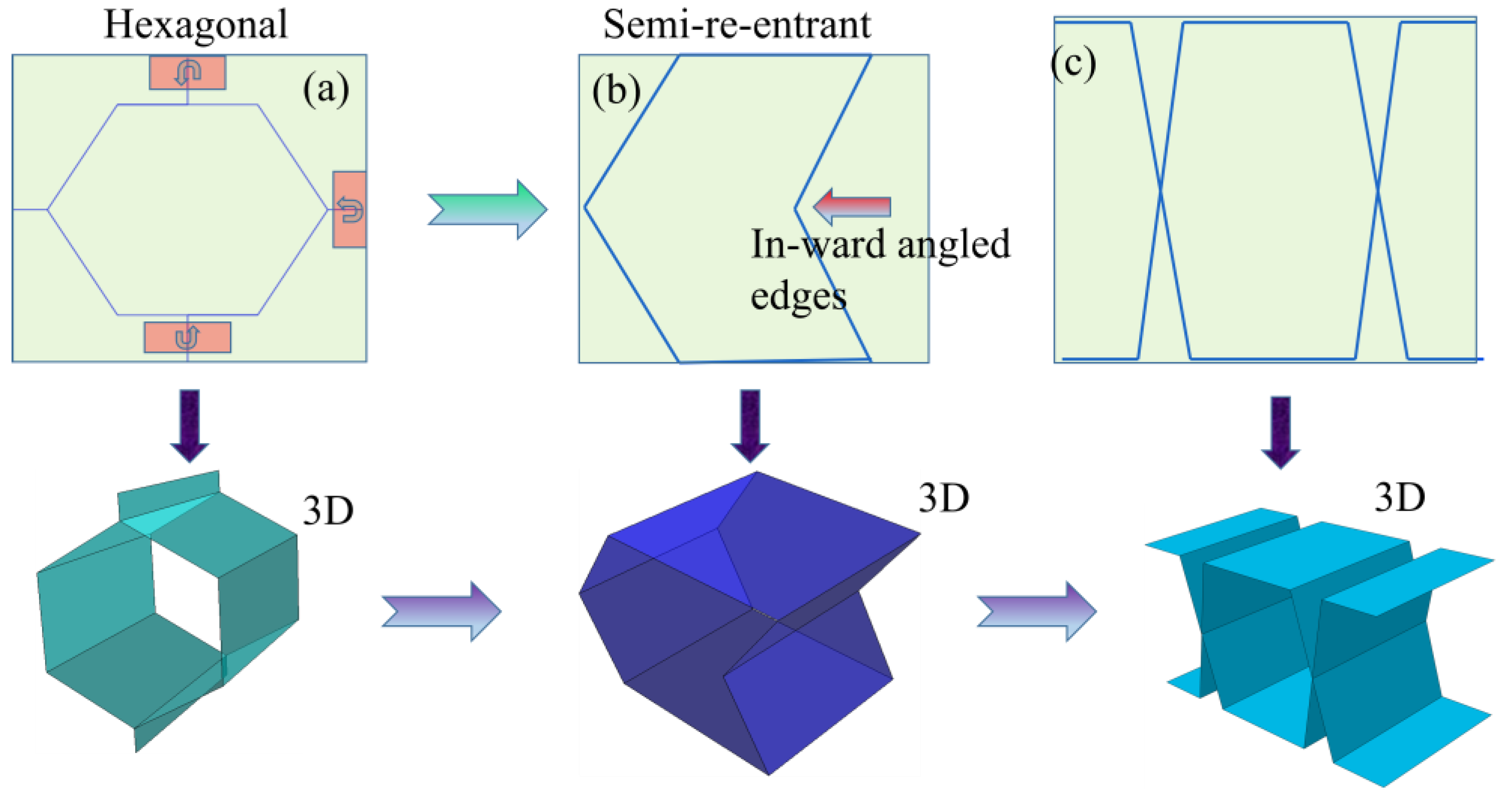
Figure 2.
Geometric representation: (a) hexagonal honeycomb and (b) semi-reentrant inspired miura, (c) trapezoidal, (d-f) unit cell with dimension, g) an architected sandwich structure with considered coordinate system, (i) 2D of the semi-reentrant configuration structure, (h & j) folding mechanism of 1D representation during deformation.
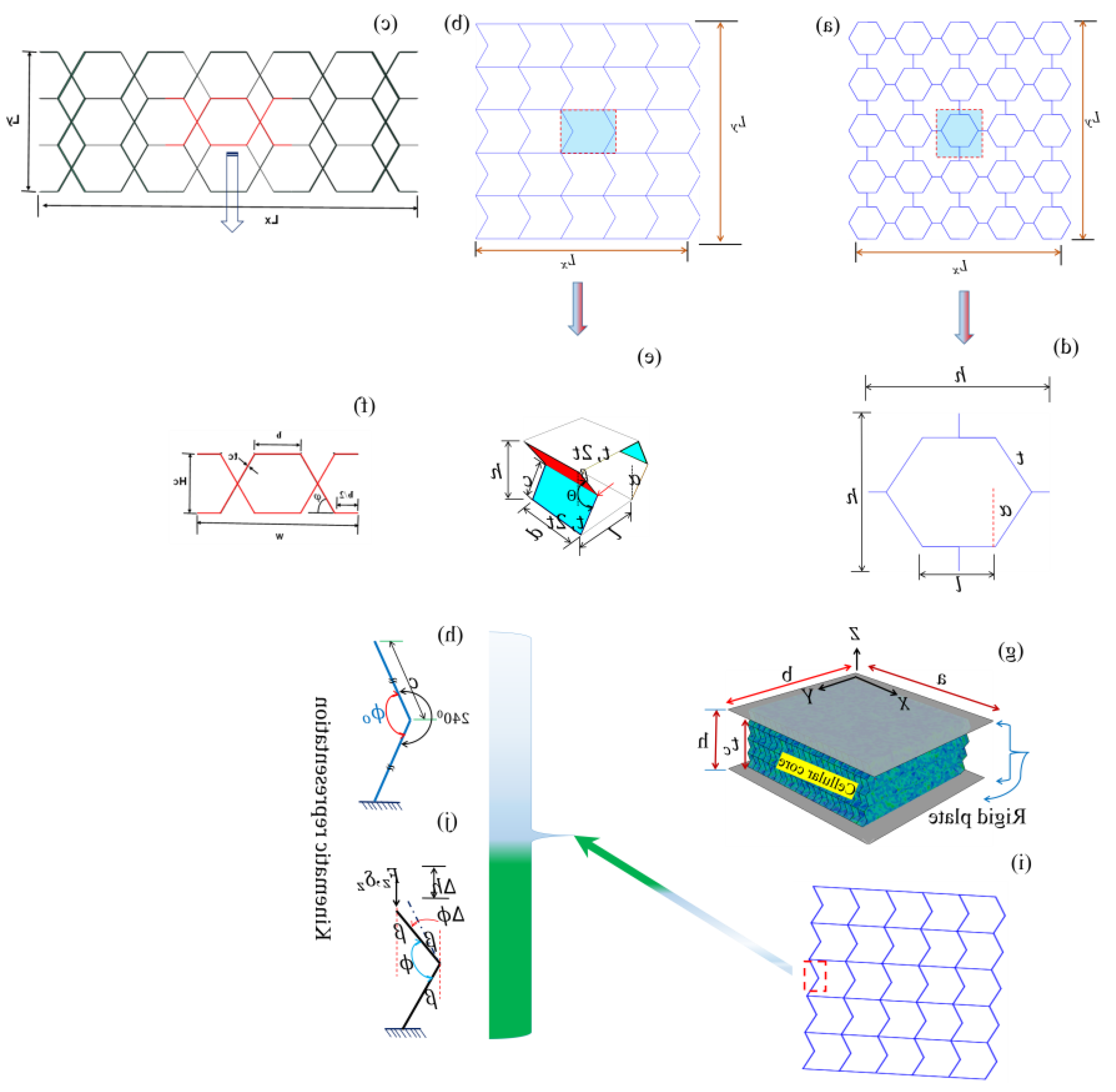
Figure 3.
Finite element compression model of: (a) semi-re-entrant Miura, (b) trapezoidal, and (c) hexagonal auxetic structure.
Figure 3.
Finite element compression model of: (a) semi-re-entrant Miura, (b) trapezoidal, and (c) hexagonal auxetic structure.
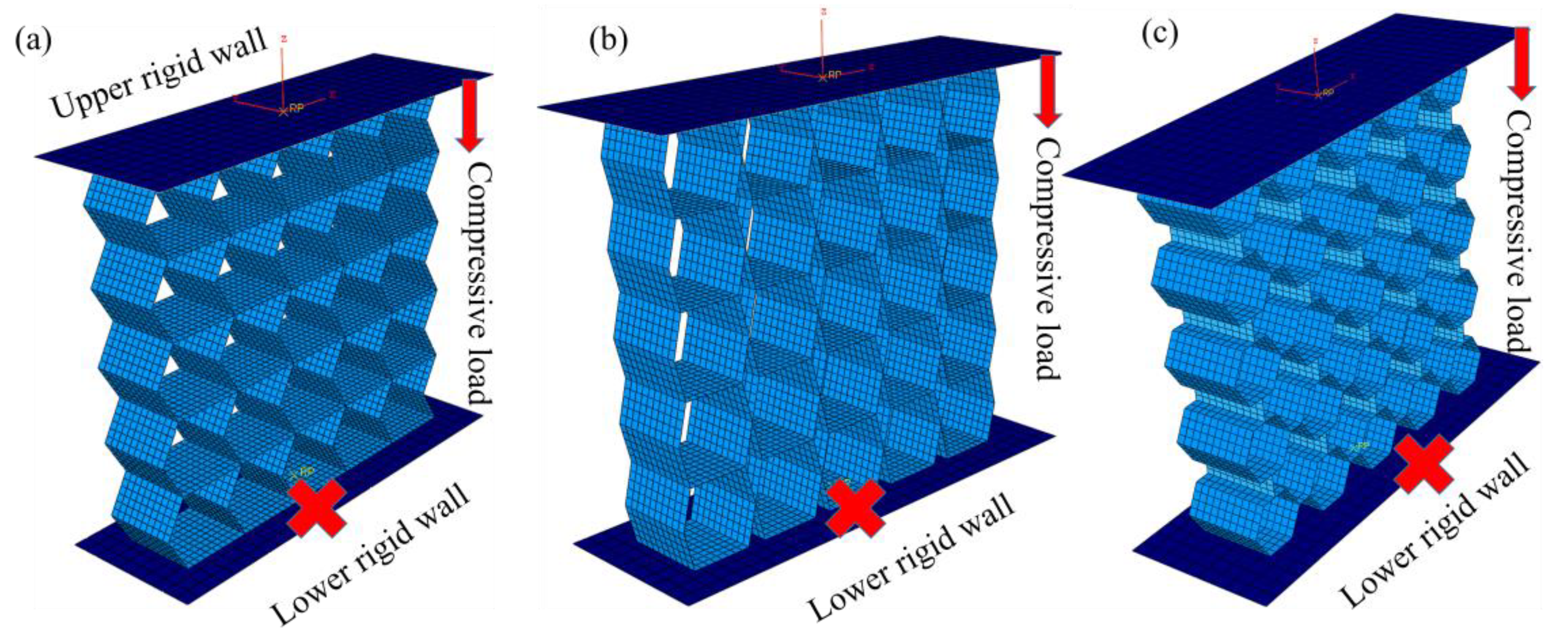
Figure 4.
(a) Comparison of force vs displacement curves for all unit cell configurations.
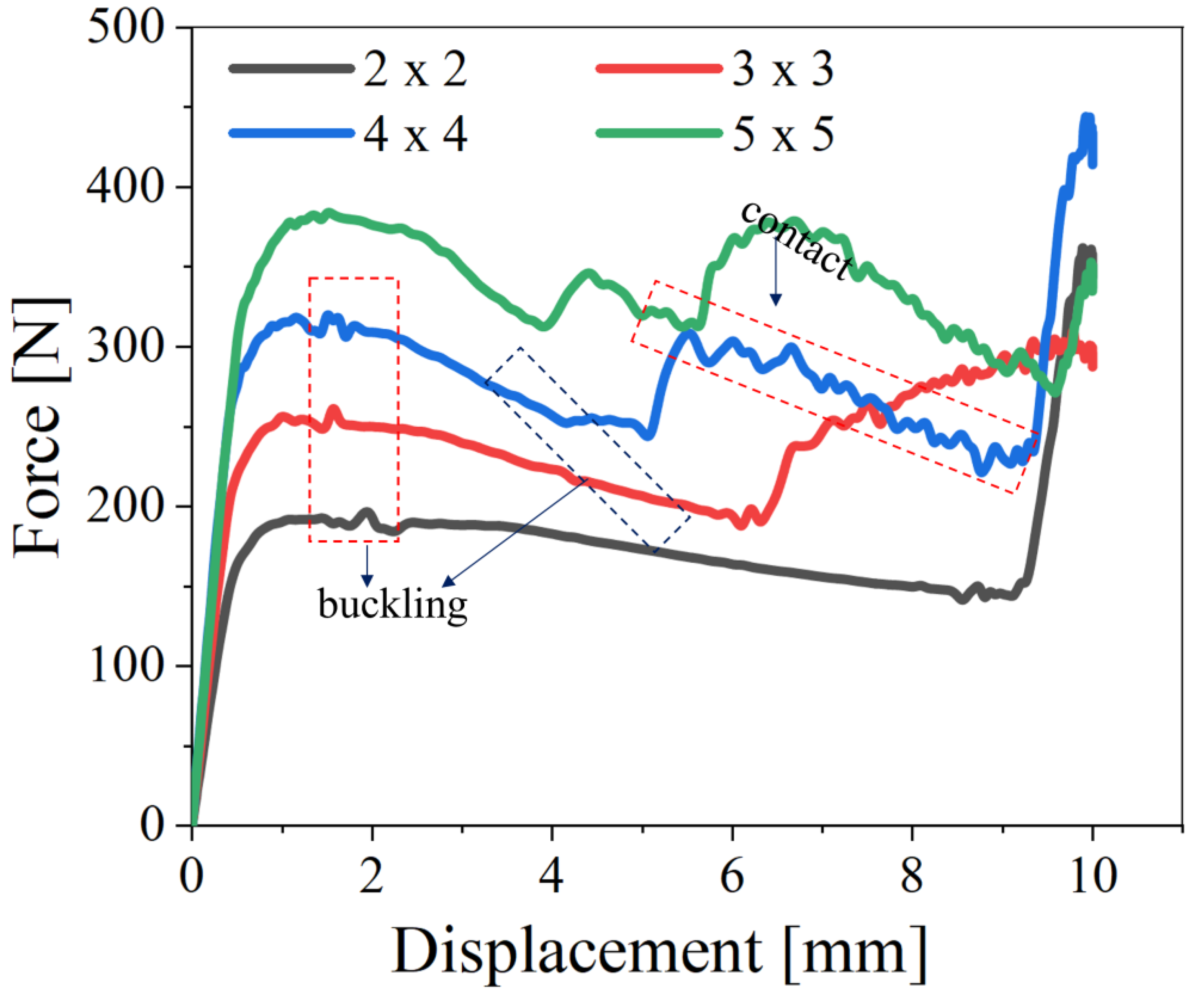
Figure 5.
Deformation of Miura origami at each unit cell.
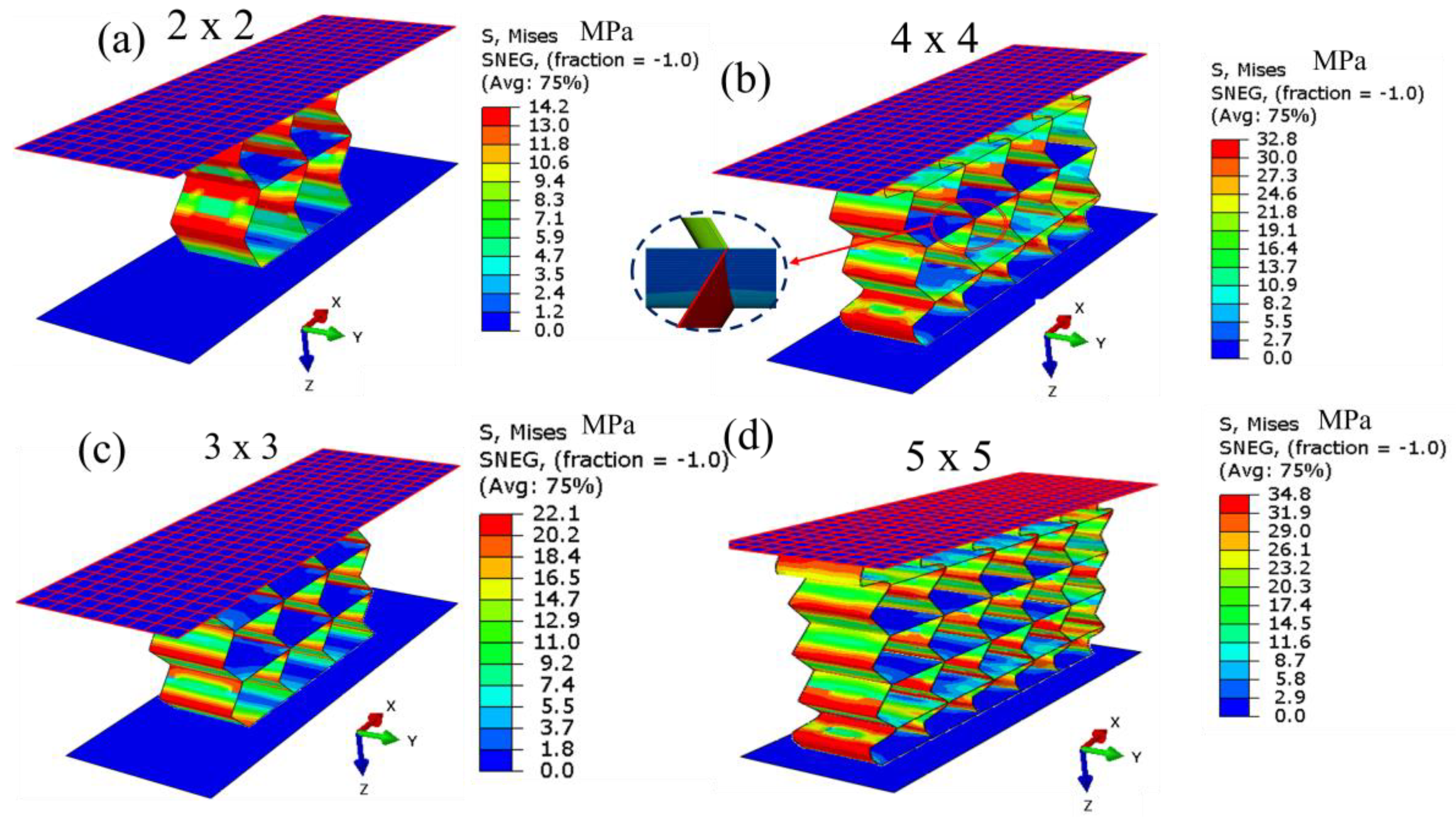
Figure 6.
FEM based simulated comparison of EA and SEA for: (a &b) 2 x 2, 3 x 3, 4 x 4, 5 x 5, (c & d) shows energy absorption and specific energy comparison using a bar graph with number of unit cell variation, f) plateau force vs miura-origami auxetic lattice configuration.
Figure 6.
FEM based simulated comparison of EA and SEA for: (a &b) 2 x 2, 3 x 3, 4 x 4, 5 x 5, (c & d) shows energy absorption and specific energy comparison using a bar graph with number of unit cell variation, f) plateau force vs miura-origami auxetic lattice configuration.
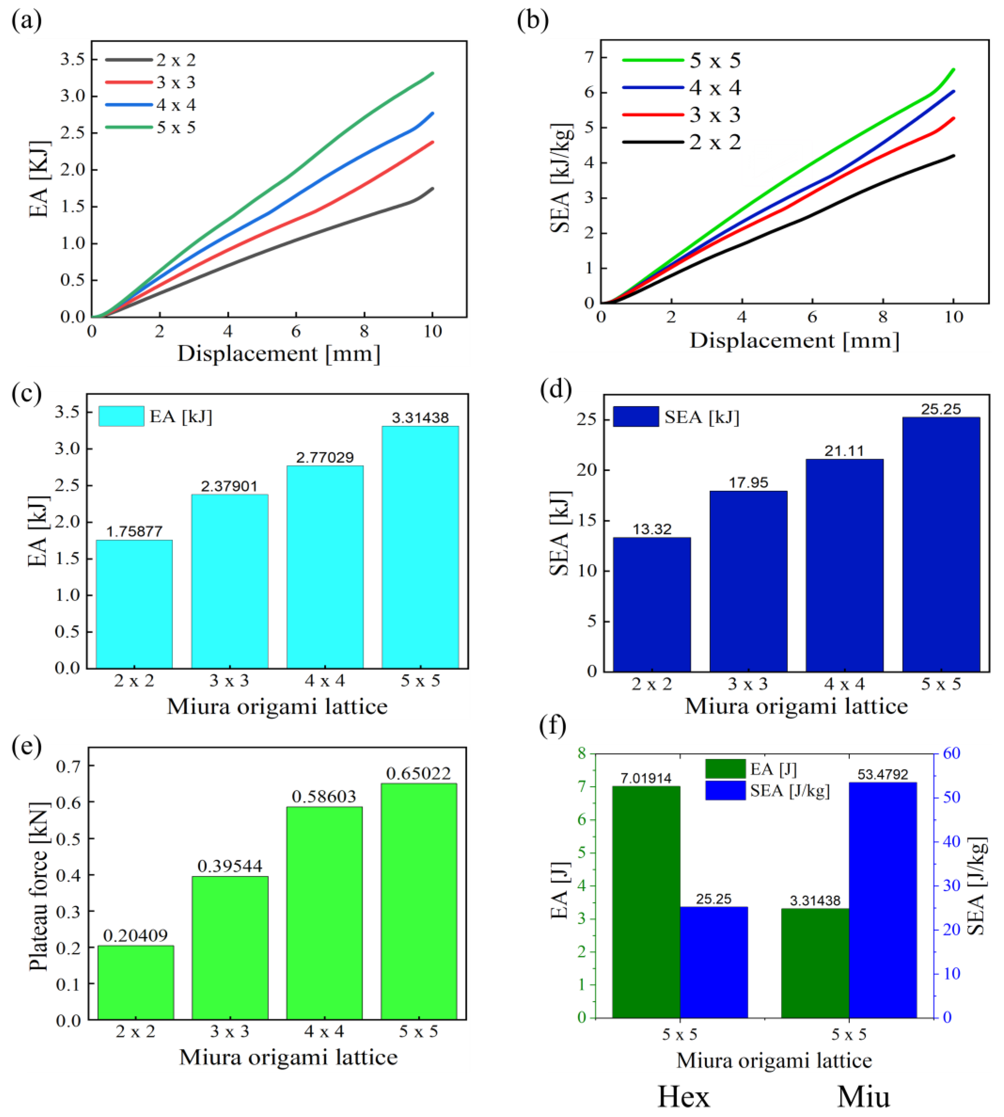
Figure 7.
Von Mises contours stress for: (a) semi-reentrant Miura-inspired auxetic, (b) Hexagonal and (c) Trapezoidal auxetic lattice.
Figure 7.
Von Mises contours stress for: (a) semi-reentrant Miura-inspired auxetic, (b) Hexagonal and (c) Trapezoidal auxetic lattice.
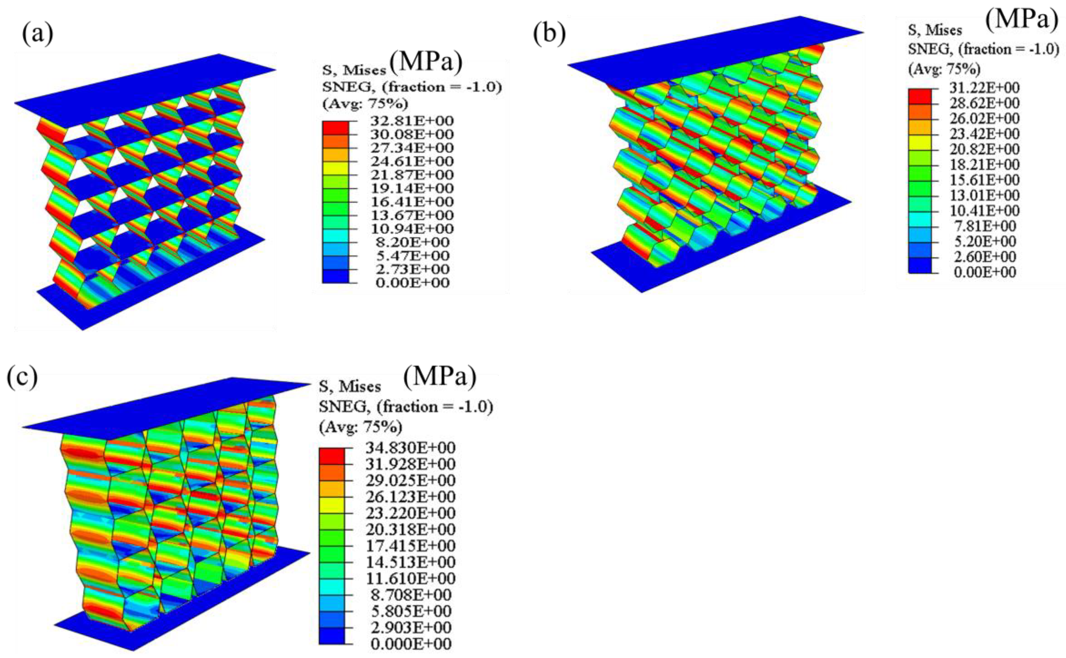
Figure 8.
Out-of-plane simulations of compressed Miura-Origami:(a & c) simulated model illustrating boundary conditions in the in-plane and the out-of-plane compression, capturing the effects of vertical deformation;(b & d) meshing using 0.8mm shell elements for the in-plane and out-of-plane compression, representing the structure’s discretization for accurate modelling of deformation.
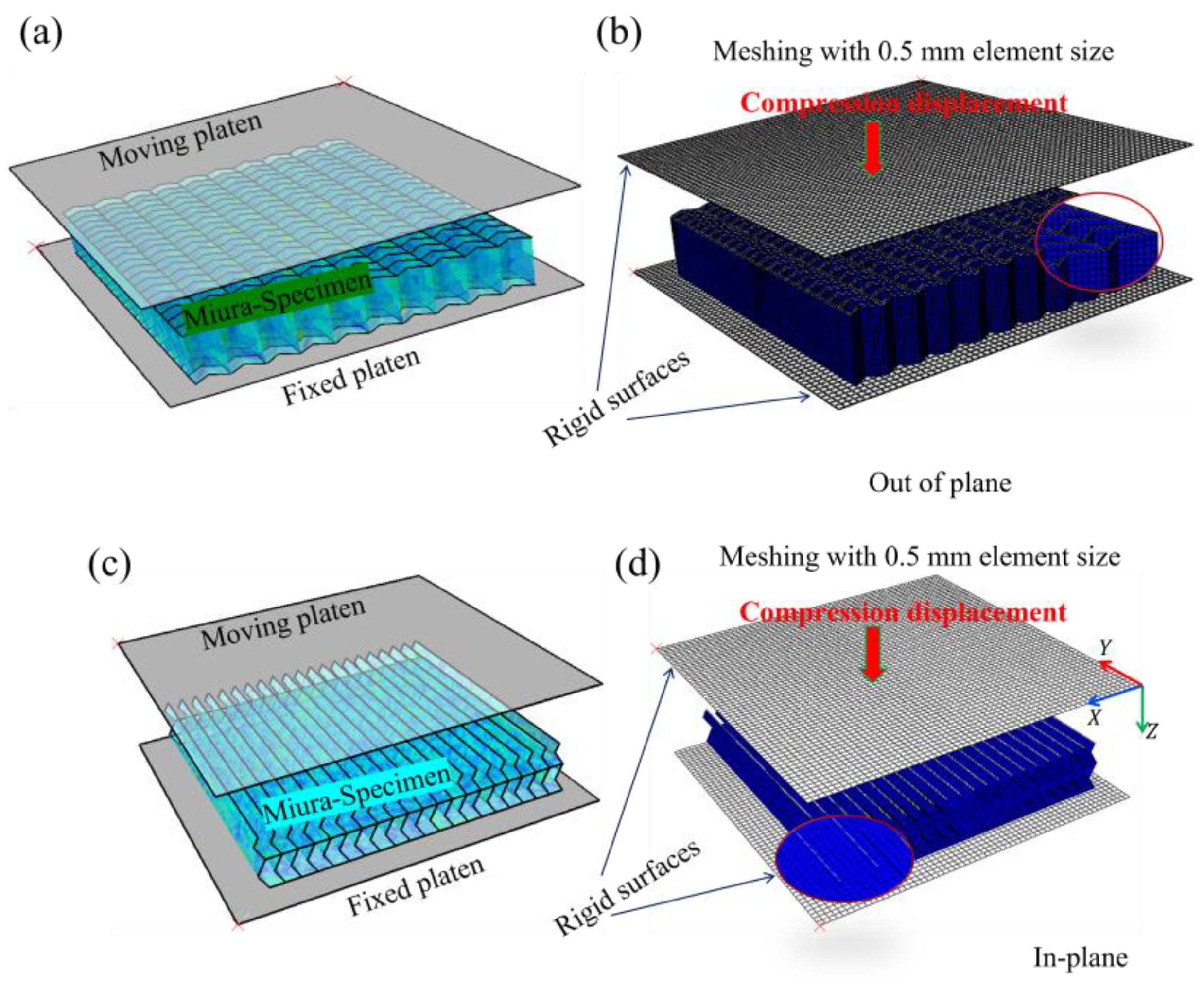
Figure 9.
The in-plane simulated deformation of the crushed Miura-origami specimen along the (Z) direction at 5.8 mm and 10.3 mm axial displacements: (a) and (b) Isometric view; (c) and (d) top view; and (e) and (f) show left and right-side (ZY) views. The contour is von Mises stress in MPa.
Figure 9.
The in-plane simulated deformation of the crushed Miura-origami specimen along the (Z) direction at 5.8 mm and 10.3 mm axial displacements: (a) and (b) Isometric view; (c) and (d) top view; and (e) and (f) show left and right-side (ZY) views. The contour is von Mises stress in MPa.
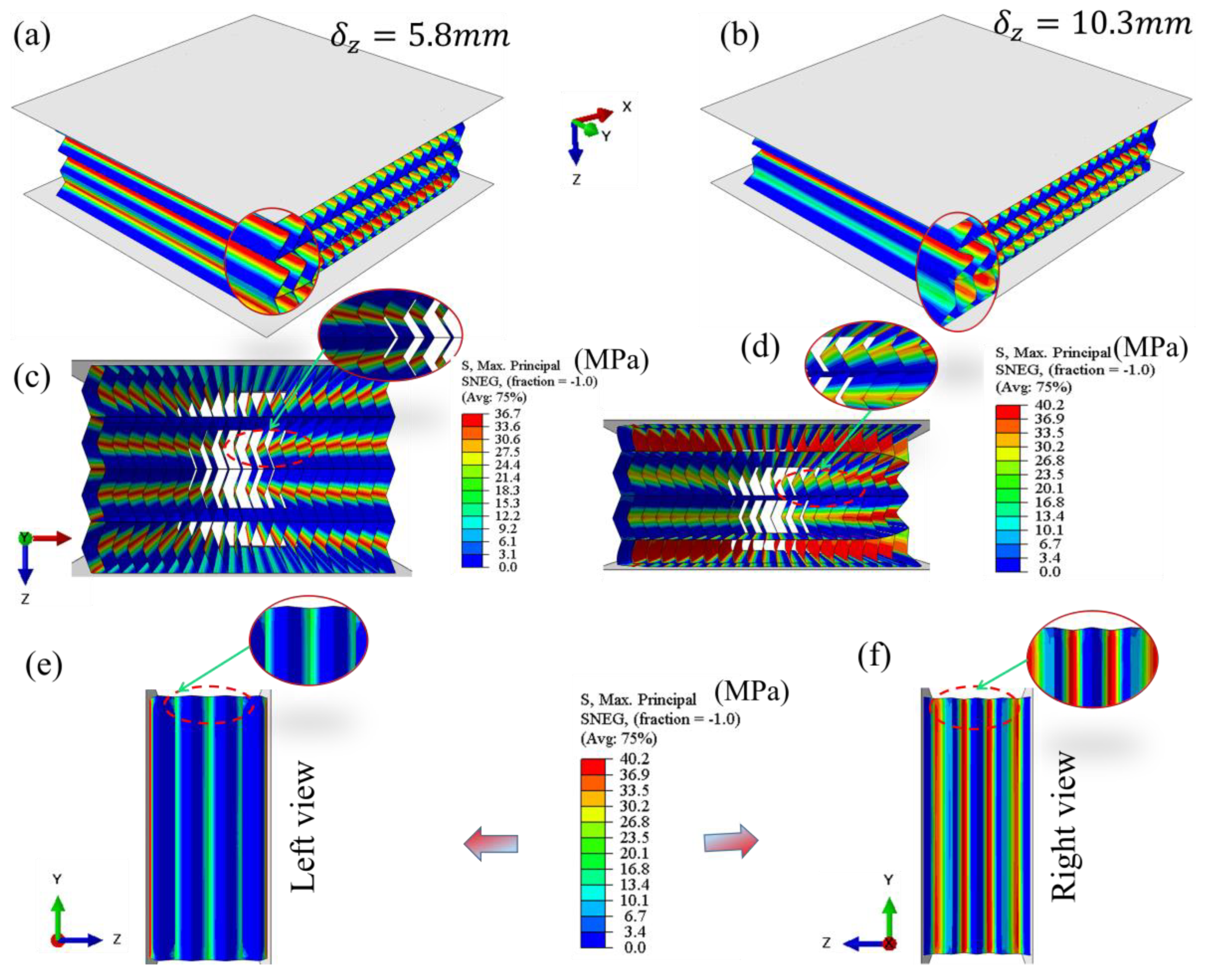
Figure 10.
The out-of-plane simulated deformation of the crushed semi-reentrant miura-origami specimen along the (Z) direction at 5.8 mm and 10.3 mm axial displacements: (a) and (b) Isometric view; (c) and (d) (XZ) view; and (e) and (f) show left and right-side (ZY) views. The contour is von Mises’s stress in MPa.
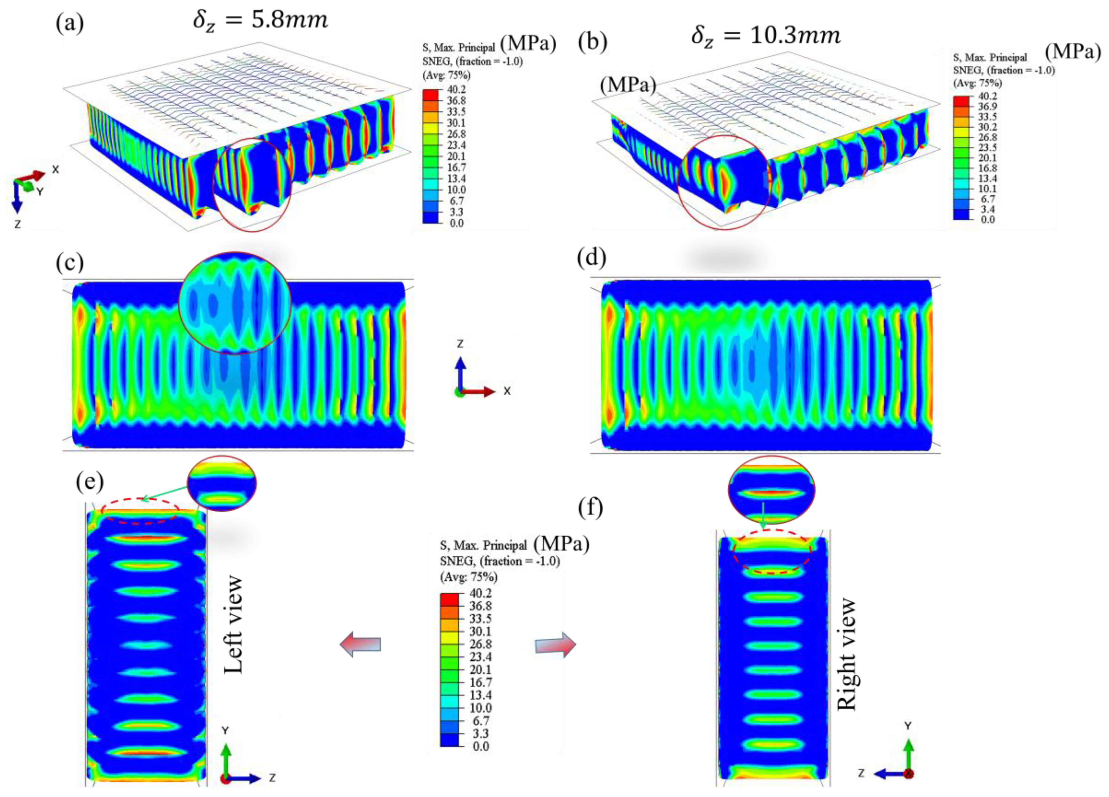
Figure 11.
The out-of-plane deformation of the crushed trapezoidal specimen along the (Z) direction at 5.8 mm and 10.3 mm axial displacements: (a) and (b) Isometric view; (c) and (d) (XZ) view; and (e) and (f) show left and right-side (ZY) views. The contour is von Mises stress in MPa.
Figure 11.
The out-of-plane deformation of the crushed trapezoidal specimen along the (Z) direction at 5.8 mm and 10.3 mm axial displacements: (a) and (b) Isometric view; (c) and (d) (XZ) view; and (e) and (f) show left and right-side (ZY) views. The contour is von Mises stress in MPa.
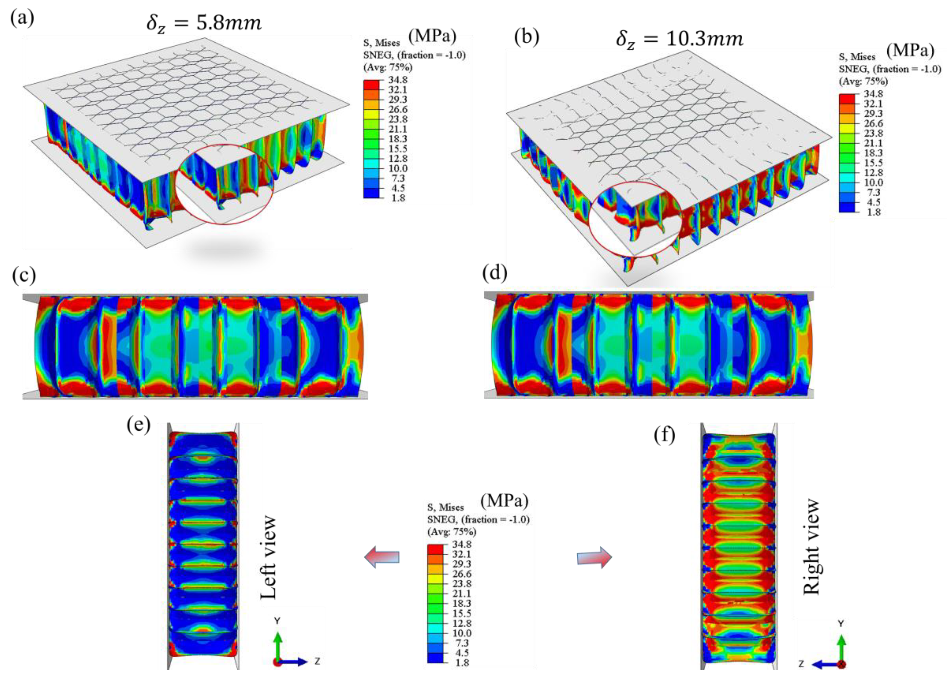
Figure 12.
The in-plane deformation of the crushed Miura-origami specimen along the (Z) direction at 5.8 mm and 10.3 mm axial displacements: (a) and (b) Isometric view; (c) and (d) top view; and (e) and (f) show left and right-side (ZY) views. The contour is von Mises stress in MPa.
Figure 12.
The in-plane deformation of the crushed Miura-origami specimen along the (Z) direction at 5.8 mm and 10.3 mm axial displacements: (a) and (b) Isometric view; (c) and (d) top view; and (e) and (f) show left and right-side (ZY) views. The contour is von Mises stress in MPa.
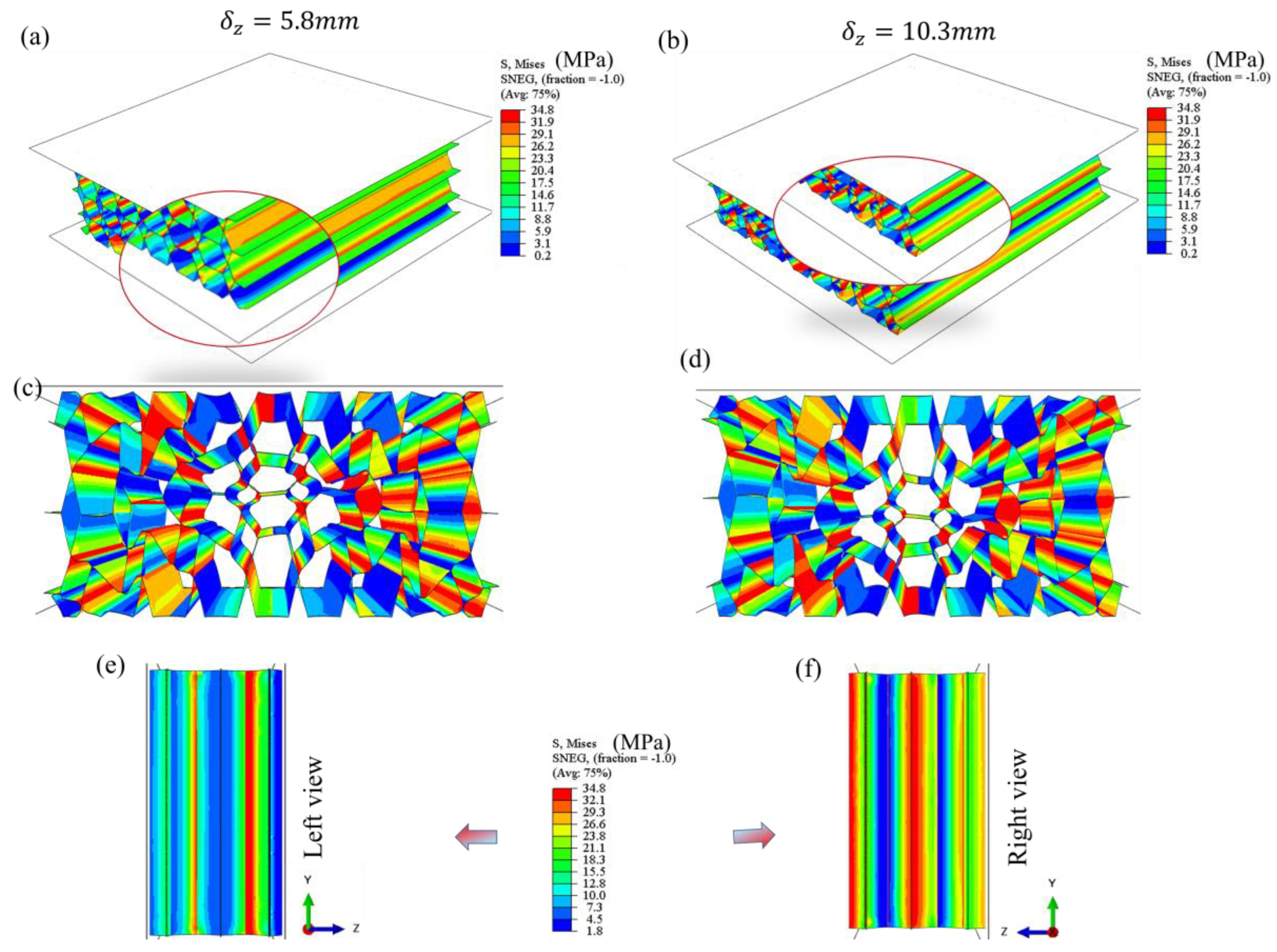
Figure 13.
Force vs displacement curve for semi-re-entrant inspired semi-re-entrant Miura-origami: (a) out-of-plane compression; and (b) In-plane compression loading.
Figure 13.
Force vs displacement curve for semi-re-entrant inspired semi-re-entrant Miura-origami: (a) out-of-plane compression; and (b) In-plane compression loading.
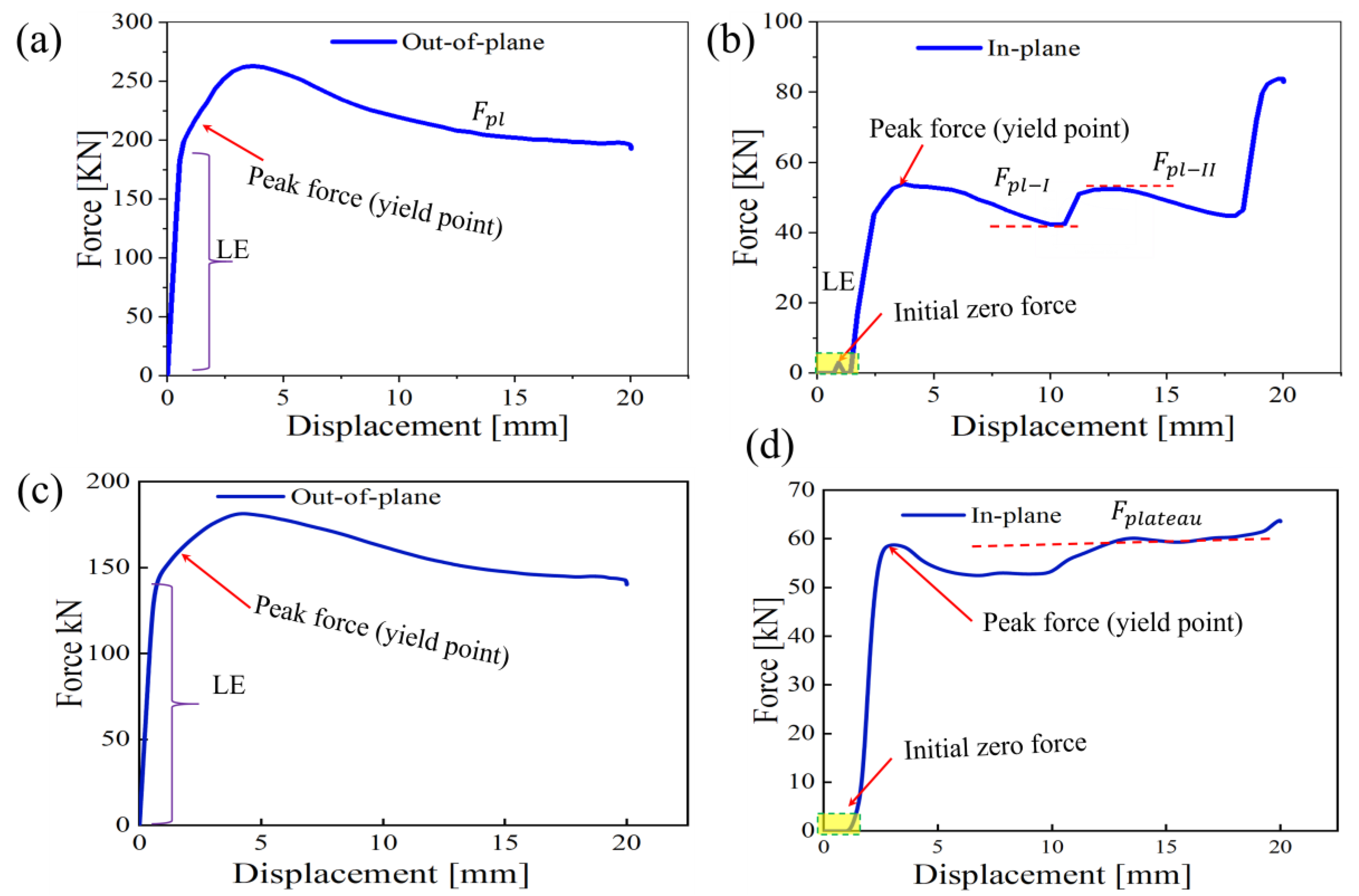
Figure 14.
Simulated out-of-plane deformation patterns of the sandwiched unit cells in the central region of the compressed specimens: (a-d) semi-re-entrant Miura origami structure at different displacement deformation stages; In-plane deformation patterns of the sandwich unit cells in the central region of the crushed specimens: (d-f) semi-reentrant Miura origami-inspired structure at different displacement deformation stages.
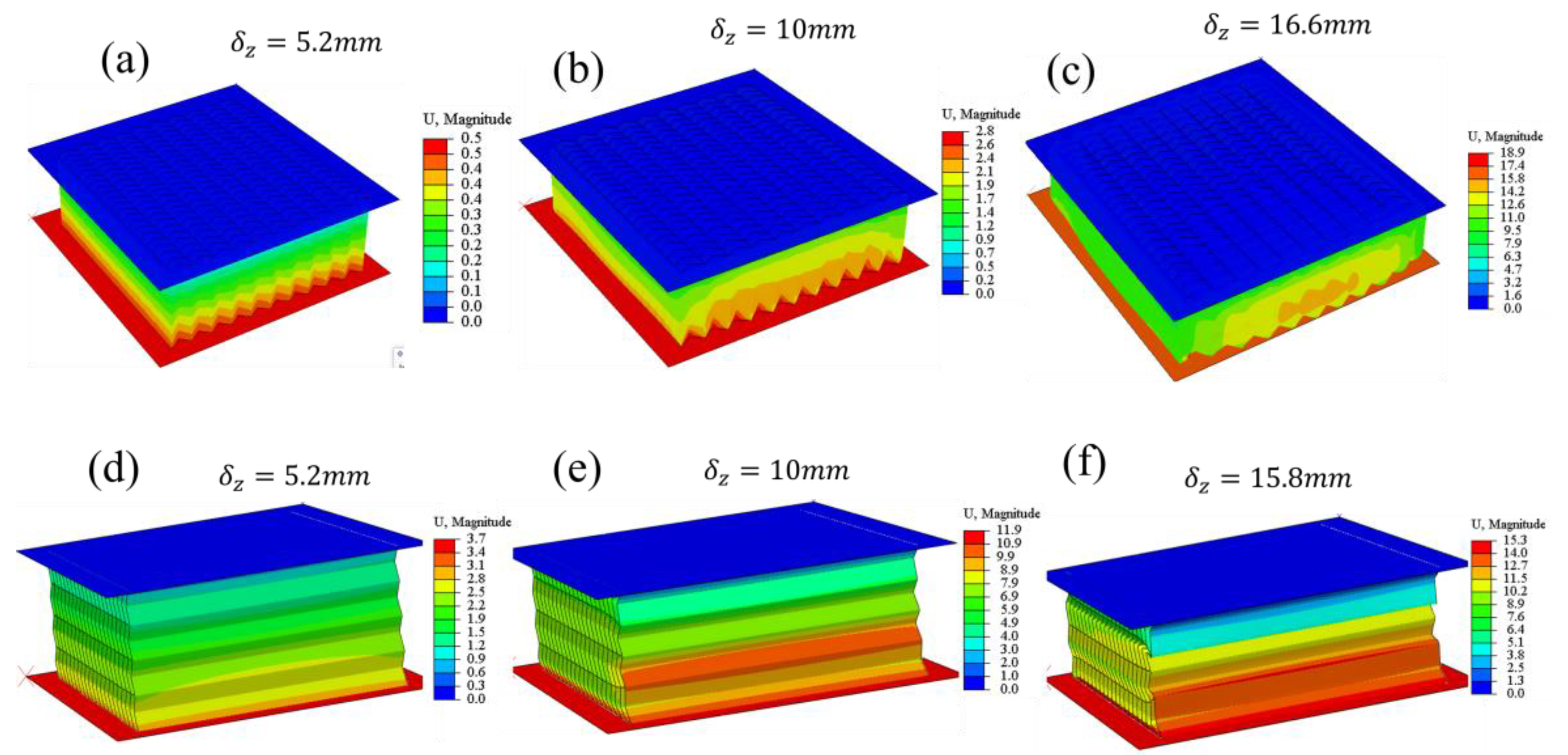
Figure 15.
Quasi-static bending test of sandwich structures with auxetic cores. (a) Comparison of EA vs displacement between in-plane and out-of-plane. (b) SEA of Miura Origami, (c) EA of Miura Origami, and (d) SEA vs displacement.
Figure 15.
Quasi-static bending test of sandwich structures with auxetic cores. (a) Comparison of EA vs displacement between in-plane and out-of-plane. (b) SEA of Miura Origami, (c) EA of Miura Origami, and (d) SEA vs displacement.
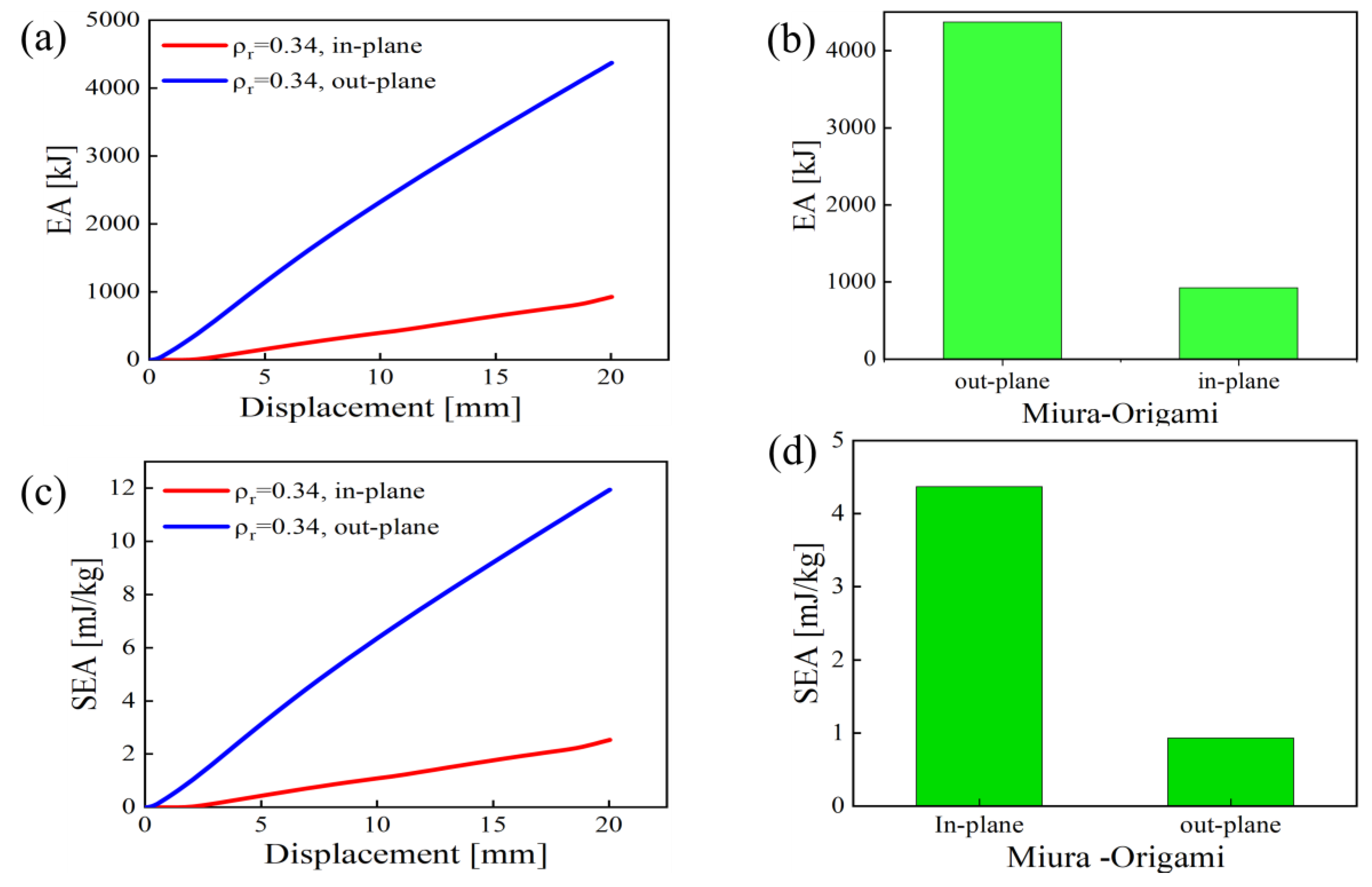
Figure 16.
Comparison of properties for out-of-plane and in-plane core cell types for sandwich structure.
Figure 16.
Comparison of properties for out-of-plane and in-plane core cell types for sandwich structure.
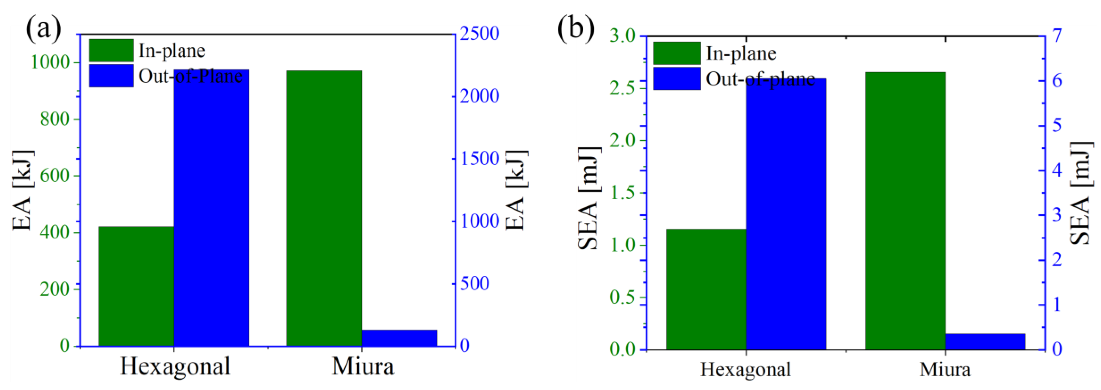
Figure 17.
Force vs displacement in-plane direction for the selected 5 x 5-unit cells: (a) Semi-re-entrant miura, (b) hexagonal lattice, and (c) trapezoidal cells.
Figure 17.
Force vs displacement in-plane direction for the selected 5 x 5-unit cells: (a) Semi-re-entrant miura, (b) hexagonal lattice, and (c) trapezoidal cells.
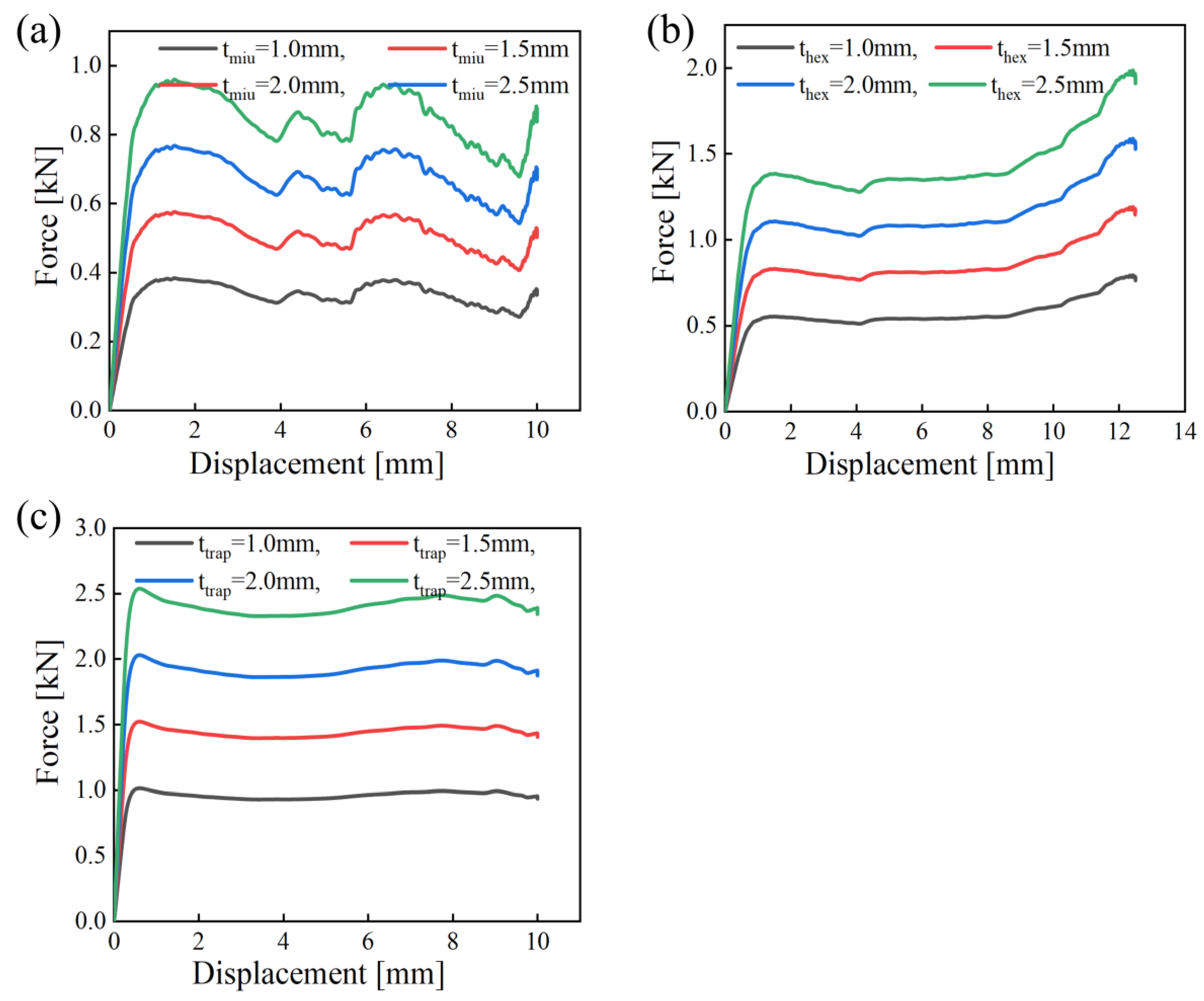
Figure 18.
The SEA and EA vs thickness variation for the selected 5 x 5-unit cells.
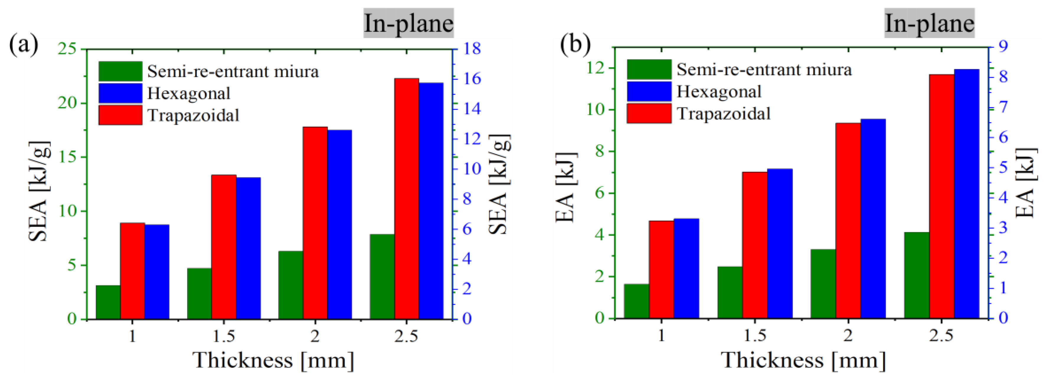
Figure 19.
Potential applications (a) Application in prosthetic structural column guards; (b) Application in multi-material approach helmet design, (c) aero plane nose design for impact resistance, (d) card dashboard for crash protection, (e ) fluttering mitigation (vibration control), and car seat cushion.
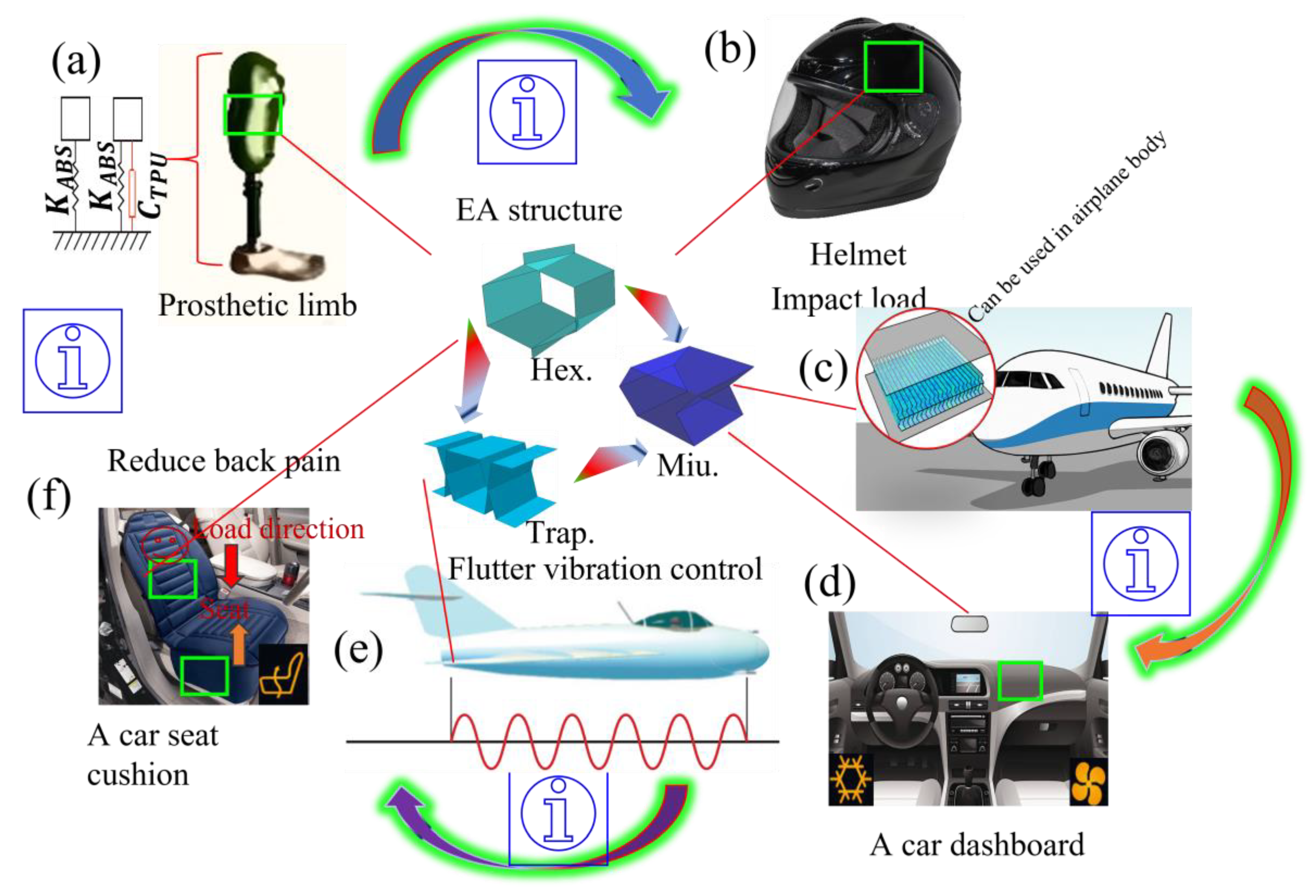
Table 2.
Material properties of ABS polymer (Etemadi et al., 2024).
| Material | Young’s Modulus E (GPa) | Yield stress (MPa) | Plastic strain | Poisons ratio (PR) | Density (g/cm3) |
| ABS Polymer | 2.2GPa | 31MPa | 0 | 1.05 | |
| 34.83 | 0.08 |
Table 3.
Energy absorption characteristics of the semi-reentrant Miura-origami inspired auxetic lattice. Note-worthy values are in bold.
Table 3.
Energy absorption characteristics of the semi-reentrant Miura-origami inspired auxetic lattice. Note-worthy values are in bold.
| Number of unit cells | Shell thickness (mm) | EA (kJ) | SEA (kJ/kg) | Mass (kg) | (mm) |
| Miu-2 x 2 | 1 | 1.75877 | 13.32 | 0.13125 | 4.1743 |
| Miu-3 x 3 | 1 | 2.37901 | 17.95 | 0.13125 | 2.892 |
| Miu-4 x 4 | 1 | 2.77029 | 21.11 | 0.13125 | 2.3315 |
| Miu-5 x 5 | 1 | 3.31438 | 25.25 | 0.13125 | 2.5405 |
| Miu-5 x 5 | 1 | 4.6764 | 8.91 | 0.13125 | 2.8512 |
| Miu-5 x 5 | 1 | 7.01914462 | 53.4792 | 0.13125 | 2.8405 |
Disclaimer/Publisher’s Note: The statements, opinions and data contained in all publications are solely those of the individual author(s) and contributor(s) and not of MDPI and/or the editor(s). MDPI and/or the editor(s) disclaim responsibility for any injury to people or property resulting from any ideas, methods, instructions or products referred to in the content. |
© 2025 by the authors. Licensee MDPI, Basel, Switzerland. This article is an open access article distributed under the terms and conditions of the Creative Commons Attribution (CC BY) license (http://creativecommons.org/licenses/by/4.0/).
Copyright: This open access article is published under a Creative Commons CC BY 4.0 license, which permit the free download, distribution, and reuse, provided that the author and preprint are cited in any reuse.


