
Submitted:
21 October 2025
Posted:
23 October 2025
You are already at the latest version
Abstract
This article addresses the problem of placing functional decomposition in Model Based Systems Engineering (MBSE) on a formal mathematical basis in order to support the development of effective mathematical models of digital twins. This has necessitated the re-examination of a number of concepts used within functional decomposition, in-cluding the representation of open systems, the specification of user requirements, the definition of inputs and outputs and the meaning of systems engineering “functions”. This resulted in the proposal to consider interactions of the system with its environ-ment rather than input/output requirements and to correctly identify the systems en-gineering concept of “function” with the mathematical concept of “functional”. By doing this we have developed a unified approach to modelling in MBSE that integrates a number of existing approaches, including Wymore’s, DEVS and Linear Systems Theory. This results in a mathematical formalism that results in a systems model that traceably satisfies the user requirements.
Keywords:
MBSE
; functional decomposition
; system modelling
; system design
; systems theory
; DEVS
; linear systems theory
1. Introduction
Model-Based Systems Engineering (MBSE) is a term coined by Wymore for the use of models to represent problems in Systems Engineering [1]. It promises to improve the application of Systems Engineering in several ways, for example [2]:
- Improved communications
- Increased ability to manage system complexity
- Improved product quality
- Enhanced knowledge capture
- Improved ability to teach and learn Systems Engineering fundamentals
Wymore’s work has not been widely adopted by the Systems Engineering community with the result that many Systems Engineering methods are still document-based and qualitative in nature, with a limited mathematical foundation. Salado has embarked on the development of a more rigorous basis for MBSE, starting from the work of Wymore and the DEVS model []. This paper re-examines some of the definitions used in the traditional approaches to system modelling leading to a unified mathematical approach that extends the work of Wymore to be applicable to the modern practice of Systems Engineering, in particular to the development of complete, traceable mathematical models (or “digital twins”) of systems under development.
2. Overview of the Functional method in System Design
System Design
We use system design to mean the activity of identifying a collection of components that can operate together to satisfy the user requirements. The components may be off-the-shelf or still to be developed. In the latter case, the activity should result in a sufficiently detailed specification to lead to system implementation.
The Functional Method
The Functional method – also called Function Based Systems Engineering [3] is one of the earliest methods for systems engineering and is widely used. In this method,the behaviour of the system, represented by the system function, is decomposed into a set of sub-behaviours, represented by subfunctions, suitably linked. These required sub-behaviours can then be used to select suitable components. The main steps are:
- Specification of user functional requirements
- Transformation of user functional requirements into system functional requirements
- The identification of the system function(s) from system functional requirements
- Decomposition of system functions
- Allocation of system subfunctions to components (off-the-shelf or bespoke).
3. The Specification of User Functional Requirements
The meaning of user, stakeholder and system requirements has been widely discussed in the literature, see for example [4]. In document-based systems engineering (DBSE), requirements are expressed in natural language, possibly subject to formal rules. In some texts there are different types of requirements known as Mission , Stakeholder or Operational requirements [3]. In general, these cover statements by the stakeholders in natural language about the purpose, performance and constraints of the system to be developed. We will summarise these as “User Requirements”, recognising that “User” may include a wide range of stakeholders - people and organisations affected by the system, and that the requirements may be of different levels of specificity.
User Functional Requirements express what the Users which to achieve by operating the system. Salado [4] describes the achievements as outcomes. They result from the changes that the system makes to its environment as a result of its interactions with the environment. For example an elevator changes the height of its contents. A water fountain changes the drinker of the water from being thirsty to being satisfied.
For this paper we use the definition of a system as a collection of parts that are related to each other, as in Bertallanfy’s definition of “a set of elements standing in interrelation”[5]. INCOSE has developed this to become “an arrangement of parts or elements that together exhibit behavior or meaning that the individual constituents do not”[2].
Let us explicitly represent those parts in the operational environment that have the system as a target as , and those that are targets of the system as . These parts may be systems, humans or may be passive objects. Call this the Context Set, .
The User Functional Requirement can then be framed as the requirements to cause specific changes to the resulting from the effects on the system of the In this paper, the changes are modelled as changes of state of the where state is used in a general sense. In a physical system, state could include measurable quantities such as
- Temperature
- Velocity or
- Height.
In a computer system state could refer to
- The value of a variable or
- An abstract state.
In the human context state can be interpreted as the state of a User’s knowledge, or thirsty/satisfied in the above example.
The User Functional Requirement is then expressed as the set of changes of state necessary to achieve the user’s needs, responding to a set of interactions impinging on the system from the environment.
Here the | symbol is used to mean “given” or “as a result of”.
In practice, the UFR this would be extracted from natural language statements of the user. For example, the primary functional need of an elevator would be “to move items between floors of a building”. In this case the are items to be moved (goods or people) and the changed state represents the people or goods on a different floor of the building. The represent any interactions that act on the system, for example the pressing of control buttons.
The performance requirements can also be interpreted in this way – the performance is measured by quantifying the change, in terms of extent, speed etc. In the elevator example we may add the requirements that the movement between floors is effected with a limit to the accelerations applied, for example.
The expression for given above does not fully describe the User Functional Requirement, since the time-dependence of the changes is not shown. This information is also needed and would need to be elicited from the User through the use of (for example) interaction diagrams. This is discussed later.
The Conversion of User Functional Requirements to System Functional Requirements
Having identified the User Functional Requirements as in the previous section, we now link these to the requirements on the system to cause the changes (and respond to the stimuli) that comprise the User Requirement.
Interactions of the System
We start from the IEEE statement [7] that the purpose of a system is “achieved by the interaction of the system with its operational environment”. The key element here is the word “interaction”. The nature of the interaction is essential to the further analysis of the system problem.
Following Lin [6] a system can be represented mathematically as a structure,
where is a set of parts and represents a set of relations between the parts. Parts may be systems. Parts may be any object in the domain in which the system is defined, for example in a physical system the parts are physical items; in a conceptual system the parts may be logical functions. In cyber-physical systems parts in the physical domain are physical items including the physical item hosting the computer processing. Within that processing part, the behaviour can be abstractly represented by a different type of part, for example, Unified Modelling Language (UML) objects.
A system designed with a purpose must interact with the environment to achieve that purpose, therefore it must be an open system. The previous representation (1) is of a closed system. A suitable representation of the required open system interacting with the environment is given by the structure:
where is the set of interactions between the elements of and the parts . is not necessarily a system of the form because the interactions between the elements of are not specified.
Let us represent an interaction of a system as
where is the source of a directed interaction and is the target - part of the environment. is the “nature” of the interaction, which represents the type and strength of the interaction. Interactions include the following types:
- The application of force
- A flow of energy or materials
- A flow of information or a signal in a cyber system
- Through a field (e.g. electric, magnetic, gravitational)
These can be quantified and assigned a numerical value called the strength of the interaction, for example a flow of electricity measured in Amperes.
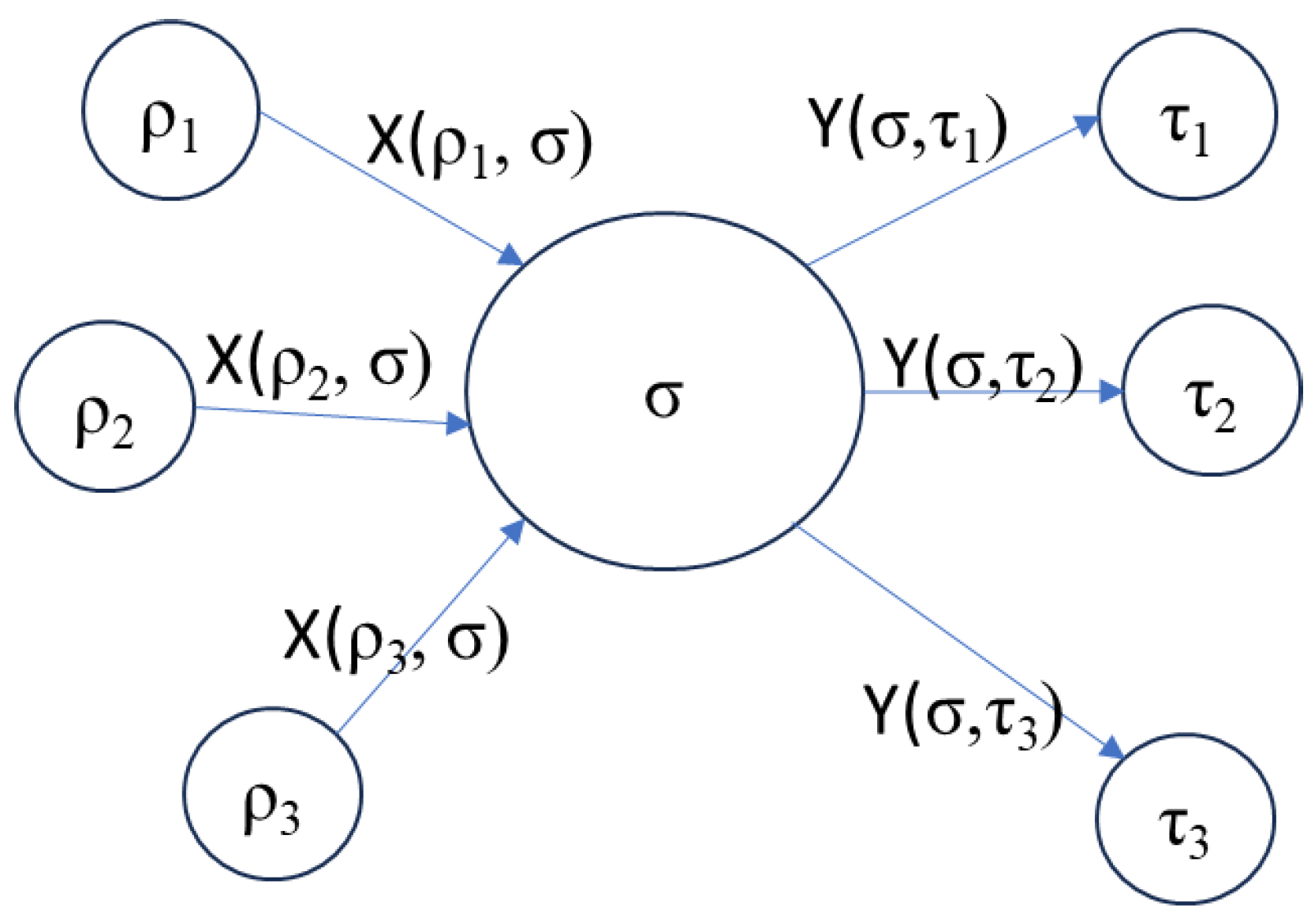
The structure, shown in Figure 1, including those entities that affects and those it responds to is:
The and represent the interactions of with the Context Set. The purpose of the system is achieved through these interactions. If the interactions with the Context Set are to have a measurable effect, they must cause changes to the state of elements of the Context Set:
In this expression, is viewed as an operation that changes the state of The combination of these effects cause the changes specified in the User Functional Requirement.
The nature of the interactions depend on the domain of the system under consideration. For a computer system, could represent something that updates the state of the operator’s knowledge, e.g. a value posted to a display. In a physical system, the interactions represent something that causes the required changes in the environment, by changing the physical states of elements of the Context Set. For example could represent an effect that changes the velocity of an object, and would be implemented through a force. In object-oriented computing, the are messages originated by that result in a change of state of In cyber-physical systems the interface between the physical and processing elements involves parts that are transducers – converting signals into physical actions and vice versa.
The System requirements for external interactions is then captured through
analogous to an input/output requirement. Note that this has been derived directly and unambiguously from the User Requirements, by identifying the interactions that can cause the required changes.
Figure 1.
Context diagram.
Comparison with Other Approaches
Buede and Miller [3] view the derivation of system requirements from user requirements as simply a restatement of the requirements from the system perspective. This suggests a form of semantic conversion that requires a degree of linguistic analysis and may be difficult to formalise.
Salado [4] draws the distinction that User Requirements (Stakeholder Needs) have solutions in a space of outcomes, while System Requirements have solutions in the space of functions. Salado views outcomes as changes of state within the set of parts . This is similar to the approach adopted here, except that we do not require to be a closed system.
In the traditional functional approach, the nature of the interaction is normally that the system produces outputs that affect the environment in such a way as to achieve the desired purpose and also responds to inputs in the desired way. The system problem is then simplified into the problem of supporting the required inputs and outputs [1,3]. This is an abstraction that considers the system only up to its boundary. Therefore, the use of the input/output view provides a convenient basis for “factorising away” the Context Set. This is not consistent with Salado’s definition of outcomes [4], since outcomes expressly involve the affected elements of the environment.
Here we suggest that the effects – changes of state - on and from the environment should be a primary consideration, with the inputs and outputs viewed solely as possible mechanisms for achieving those effects. The designer then has the latitude to select the optimum interaction that can achieve the desired change of state. This change of emphasis allows a more direct linkage of User and System requirements and also allows for a more general system solution, as will be demonstrated.
The removal of the Context Set limits the scope of the designer to develop alternative methods of causing the required changes, resulting in a lack of generality in the solution. For example, if the required outcome of an alarm system is to deter burglars, this could be achieved by an audible alarm or a flashing light. If the context of “burglars” is removed I may restrict myself unnecessarily to a system that only produces an audio alarm as an output. Another example is a system to heat water. The heating effect could be obtained by the conduction of heat into the water, or by the absorption of RF energy as in a microwave. Without knowing the purpose of the output we cannot optimise the delivery mechanism. If we select the conduction mechanism, this further informs us that the heat must be produced by a heating element that is designed for immersion in water.
This emphasises the importance of retaining references to the Context Set where possible, and using an effect-based rather than an output-based design strategy. The System Designer must then consider all possible outputs that create the required changes, and must optimise the delivery mechanism. At the design stage, a knowledge of the application of the system can provide important contextual information relating to the selection of suitable parts, and that the information on the elements of the Context Set can be generalised as necessary to avoid dependence of the solution on one particular example of the Context Set.
Functions
Traditional functional approach
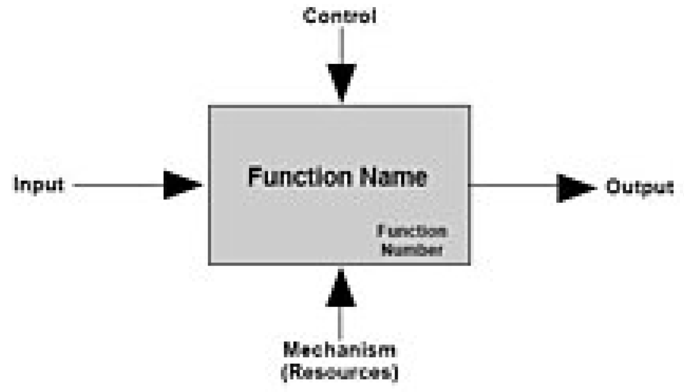
In traditional Systems Engineering, the strictly mathematical definition of a function as a mapping from elements of a domain to elements of a codomain is broadened to indicate an object that can transform inputs, represented by text descriptors, to outputs labelled in the same way [8]. The intended process is indicated by the name of the function – often a verb/noun pair, as in IDEF0 [9]. In this approach the inputs/outputs and purpose of the function are all implied by text labels, with the human designer required to provide the necessary interpretation in physical terms.
Figure 2.
IDEF0 Representation of a function.
Wymore provided a more precise mathematical definition of a logical function using a state machine approach, where the functional definition of a system is given by:
where IZ and OZ are sets of input and output states, SZ is the internal state of Z and NZ and RZ are parts of the state machine representing the behaviour of Z. The system relates the “Input trajectory” – the sequence of IZ elements presented to Z, to the output trajectory – the sequence of OZ.
Although a more mathematical formalism, it is sometimes difficult to relate to physical processes, since it relies on the tokenisation of physical items and the use of discrete events to represent the dynamics of the behaviour, which is often more naturally represented by continuous functions.
The mathematical theory presented by Wymore was chosen primarily for pedagogical reasons. According to Wymore’s autobiographical account, referenced by Estafan [10] “restrict[ing] all of MBSE to discrete time and that the basic set of system models would be the set of sequential machines with Moore readout functions. These decisions freed me from topological considerations occasioned by aspects of continuous time to allow me to concentrate on the mathematical structures of the objects of interest to systems engineers”.
In the interactional view presented in this paper, we use functions to represent the behaviours of systems or parts in terms of the conversion of interactions acting on the system or part into interactions originating from the system or part. This is different from the standard input/output approach as discussed in the following.
Inputs and Outputs
The previous examples use the standard concepts of input and output. These concepts are readily understood in the context of computing systems, where typically the inputs are the arguments of a function and the outputs are the returned values. However, when we try to apply this metaphor to interacting physical systems there are a several subtleties.
Consider the example of a kettle. The conventional statement of the kettle function is that it transforms cold water (the input) into boiling water (the output). The transformation happens as a result of the kettle acting on the cold water. In this paper, we focus on the interaction of the kettle system (an element of S) with the water (an element of C). Throughout the process, the water remains an element of the environment, C : input refers to the initial state of the water and output to the final state. The only sense in which the water “goes into” the system is that it is temporarily contained by the system, S : it is never part of the system. This also applies in the elevator example, where the passengers could be considered inputs and outputs of the operation of the system in the given environment, but in the model used in this paper they remain elements outside the system that are acted on by the system (see Figure 3).
An input continues to be part of the environment that temporarily interacts with the system. A way of describing this is that the input (target) is associated with the system until the interaction changes the state of the input to an output – a Transformative Function according to Kossiakoff et al. [11] We model the temporary association by a containment interaction that changes the state of the target from “free” to “contained”.
In some cases inputs and outputs are not evident. The Earth orbits the Sun in the Solar System by virtue of a gravitational interaction between them but there is no input and output in the conventional sense. Another semantic problem is the direction of flow suggested by the terms input and output. For example, the suction produced by a vacuum cleaner is a flow of air into the system, but since it performs the function of the system, it should perhaps be classed as an output. Similarly for the cooling effect of a refrigerator which actually represents a flow of heat from the content into the refrigerator system, so again should be classed as an input. In these cases we again propose that interaction is a more appropriate term.
The Identification of the System Function
In the interaction view of this paper, we use a function as an expression of the behaviour of a system that describes how the interactions originated by the system (actions) are generated, as a result of interactions originated by external parts acting on the system (reactions). We need to quantify the interactions to place them in a mathematical framework. We have established that the analogue of the system input/output requirement can be represented by
is interpreted as the strength of an interaction (e.g. the force applied, the field strength, the heat flow, a number). Let the set be organised as a vector with a time dependence .
In general, the actions at any time may depend on the sequence and history of the reactions. In this case we need to transform from entire history of the time-dependent incoming function into an outgoing function Mathematically this is a transform or functional – a type of function that takes the values of a function over time as its argument and produces a specific value at a given time.
This may include an integral transform of .
In the same way, the current state of the part described by the function can only depend on the history of the incoming interactions and the original state:
is a procedure for converting the evolving input stream into an output stream . This can be implemented in a number of ways:
When the system actions at time t depend only on the reactions at time t (i.e. with no history), we can write , where is a simple (mathematical) function. As an example, suppose is an electrical heating element with input current X(t) and output heat Y(t), we can write , where R is the resistance of the element.
Where the description of the system is event-based, for example in a cyber system, a Finite State Machine may be used to calculate and . This is the approach selected by Wymore for pedagogical purposes [1] and by Ziegler for the DEVS model [13], where the actions and reactions are treated as input and output events, for example a function is modelled as:
where are sets of input and output events and are the elements of the state machine. Given a sequence of input events , the state machine generates a sequence of output events .
The complete expression of the behaviour of , shown as is then given by:
This expression represents the functional requirements on the System . In addition to the actions, and reactions, , the functional describes how the actions depend on the stream of reactions through time. While the actions and reactions required can be deduced form the User Requirements for external changes of state, the requirement for results from the User’s Requirements for the sequencing and magnitude of the actions and reactions.
The Decomposition of the System Function
The aim of functional decomposition is to break the system into subfunctions that represent the behaviour of known parts that can then work together to achieve the required system behaviour. The required functional behaviour can be decomposed using a conceptual system for which the parts,, are functions that can ultimately be assigned to real components. In cyber systems designed using an object-oriented approach such as UML, it is more common to use a study of the requirements language within the domain to derive analysis classes directly, which can then be refined iteratively into design classes. In this cases the design classes or object instances form the parts in the system model.
Let the system function be decomposed into a further set of subfunctions, . These functions must together satisfy the system functional requirements. The functional model, including its interactions, is now shown by:
where is the set of interactions between subfunctions, and is the set of interactions with the environment. represent the internal links between the.
In this expression there must be a link for each to one of the new functions that replaces the link to the original system function. Similarly for each , replaces . This is a level-balancing or mereological law [14]. In addition, the behaviours of the subfunctions, must combine to produce the required behaviour of the system, . Proof of this typically requires detailed modelling, for example using the DEVS model [13], a consideration of the system homomorphisms [1] or analysis of the combination of transforms that arise, using (e.g.) Laplace transforms [15].
Figure 4.
Functional Decomposition.
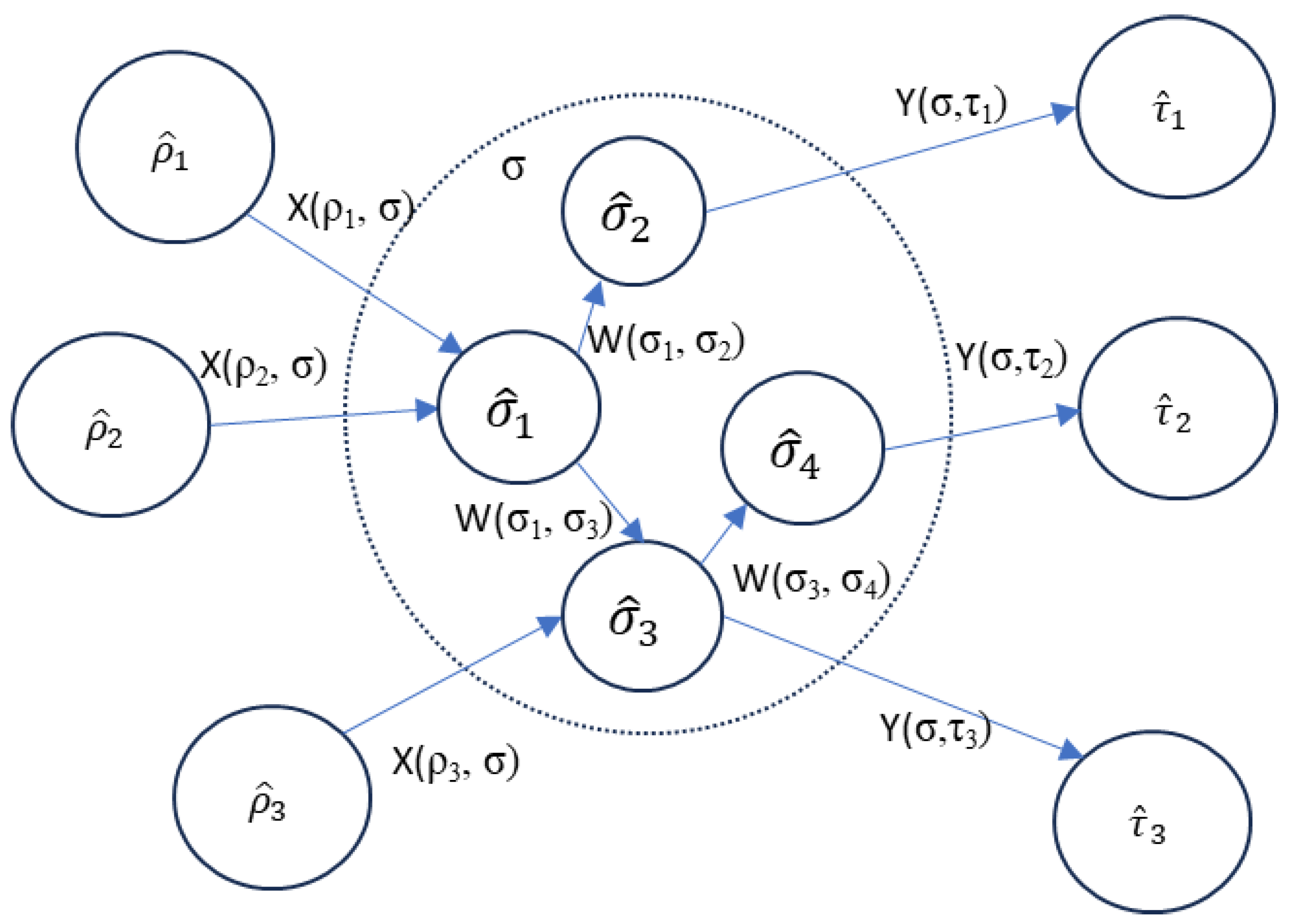
The original function is replaced entirely by the sub functions . and can now be disregarded. There must be no remaining links to or from the original function. The (inner) boundary functions and characterise the interactions with external parts. There should be no links from subfunctions to new elements outside : these would represent side-effects of the system . Equally, all incoming links must connect to a subfunction. This means that the interactions required of are produced by the boundary subfunctions. The benefit of the interaction approach is that we can use the knowledge of the required effects of the system to give insight into the type of boundary part that can most effectively provide the required interaction. If the SOI is an electric kettle, we know that a boundary function must provide heat to the water in the kettle. Knowing that the target is water, we must therefore find an immersible heating element. If we only know that the output is heat, any number of unsuitable parts could be considered.
Further decomposition of any of the resulting subfunctions is possible, and follows the same pattern as the decomposition of the system function, as discussed in [16] . This provides a scale-invariant approach since the Context Set for each subfunction is now the union of the remaining subfunctions and the functions from the original Context Set:
Further decomposition results in subfunctions of the form:
where
The end result of the decomposition process is a set of “leaf” subfunctions. The aim is to define “leaf” subfunctions that can be implemented through known physical parts or software components.
Salado [4] does not agree with this approach to decomposition: “The SOI is conceived as an open system that executes a function. Establishing stakeholder needs for the components (and, hence, a problem space of outcomes for the SOI) would require conceiving the SOI as a closed system, which is impossible to do without losing information (removing external inputs and outputs into/from the SOI). Therefore, the SOI’s function is decomposed into a set of functions (those to be executed by its components) that cannot be converted into outcomes.”
Our position is that the system plus its Context Set () - equivalent to the Context System for the SOI in Salado’s terminology - does not necessarily need to be conceived of as a closed system (or even a system), because elements of the Context Set may further interact with other elements that are outside C . In effect, the outcome required by the SOI Stakeholder may be an intermediate outcome. The change in state within C may result in a further interaction outside If I boil water in a “kettle SOI”, the resulting boiling water can further interact with (say) coffee in a “coffee-making SOI” to form brewed coffee. There are two (nested) outcomes – the water is boiled (1) and the coffee is made (2).
Further, we do not need to establish Stakeholder Needs (User Requirements) for each component, since we already know how the components will respond to and generate interactions with other components (from their specifications – see the next section). We do know that the boundary functions are subject to the User Functional Requirements since they are the functions that respond to and generate the interactions that satisfy the User Functional Requirements. The boundary functions must produce the outcomes required of the system.
Allocation of System Subfunctions to Components
The functional model developed up to this point is a conceptual or logical model of the required system, expressed as functions – the required behaviours of parts. Ideally we should be able to find or design parts that meet the functional requirements. However, it must be recognised that the functional decomposition cannot be completely arbitrary, it must be guided by the designers knowledge of feasible (buildable) parts. In Wymore’s tricotyledon theory [1], the system must be buildable from the set of available parts and must also meet the requirement of the functional model. We anticipate that there is a set of available parts with known functions. For automation of the design process, the functions of known parts could be catalogued to support a search function. Where no part exists with the required function, the function can be used as a basis for the specification of a new part, or potentially further decomposition into a set of new parts.
Assume we have a set of pre-defined parts with functions:
For each in the functional model we need to find such that:
and
In other words, the required part must provide at least the interactions in the functional model. In addition the behaviour of the part must be equivalent to the behaviour specified by the functional model.
In these expressions, and represent classes of parts with which has a known interaction. These are selected as representative of the modelled parts and For example, assuming the SOI is a hi-fi system, the functional analysis will result in something that amplifies the audio signal and something that converts the signal to sound energy. Amplifiers are specified according to their performance when paired with speakers of a particular impedance.
Where the part has additional (unwanted) interactions, it is necessary to find a way of either suppressing or absorbing them. For example, many electrical components generate unwanted heat, which make it necessary to provide cooling. Electrical components may also require electrical power as an input. The behaviour of the part must be such that the relationship between its interactions matches that required in the functional model to the extent that it is necessary to result in the same overall system behaviour.
Design Strategy
The observation that the boundary functions provide the behaviour required of the system can be used to support a composition approach to design where suitable parts are identified that produce the boundary interactions and the system is then constructed to link those parts together – this is known as functional composition.
Coffee Machine Example
The following provides a simple example of the application of this approach to the design of a coffee machine.
Specification of User Functional Requirements
Consider the example of a coffee machine. The User Requirement for changes to the environment can be expressed as:
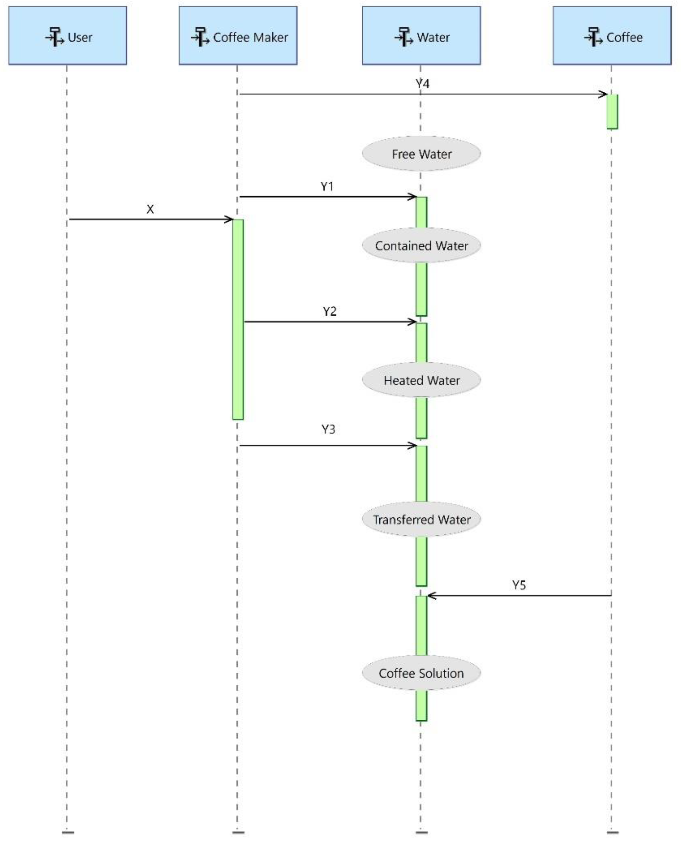
The user requirement can be refined at the user level by specifying individual steps in the process:
The Conversion of User Functional Requirements to System Functional Requirements
We therefore require that the system supports the actions that cause these changes of state. Specifically we require:
and has a reaction to
As illustrated in Figure 6:
The Identification of the System Function from the System Functional Requirements
This results in the system function , illustrated in Figure 6. Here is the functional describing how the actions depend on the reaction We do not have an explicit mathematical form for but we can deduce the sequencing from the User Requirements for the coffee-making process, and that the process should be initiated by the on/off switch.
Now we proceed to quantify the actions that the system must produce. From the User Requirement we can determine that the system must produce the action that changes the state of the Water from Free to Contained
This can trivially be modelled by a state machine defined by
as:
The system must also produce the interaction that causes the following change of state:
The water is modelled as a linear system = , with the state variable representing the temperature of the water. The water is when reaches a user-defined value. We now consider options for , an interaction that changes the temperature of the water. As previously discussed, this could be through microwave heating or a conduction or convection solution.
We find that if is a flow of heat that acts on the water then:
Where H is the heat capacity of the water. If we integrate this we find:
illustrating that indeed is a functional of . This allows us to quantify the required heat flow, based on the mass of water to be heated and the time required. We continue using a similar approach for and .
We now consider where coffee acts on the heated water coffee to dissolve in it. The water is now modelled as another linear system , where the state variable represents the concentration of the coffee.
C may be modelled as
So that
This allows us to quantify further the brewing time for the coffee.
Finally we consider the incoming interaction , where the user controls the operation of the coffee maker by pushing a button. We propose a simple state machine for this:
Decomposition of the System Function
We now require to decompose the system into parts, with the quantitative knowledge of the changes that the boundary parts are required to produce.
The functional requirements of the boundary parts are then:
- causes the water to be contained
- 2.
- —causes the water to be heated
- 3.
- —causes the water to be transferred (to mix with the coffee)
- 4.
- —causes the coffee to be contained
- 5.
- —causes the coffee machine to switch between active and inactive
An initial trial decomposition is shown in Figure 7, where each (boundary) interaction has been assigned to a different part.
Figure 7.
System Function for Coffee Maker.
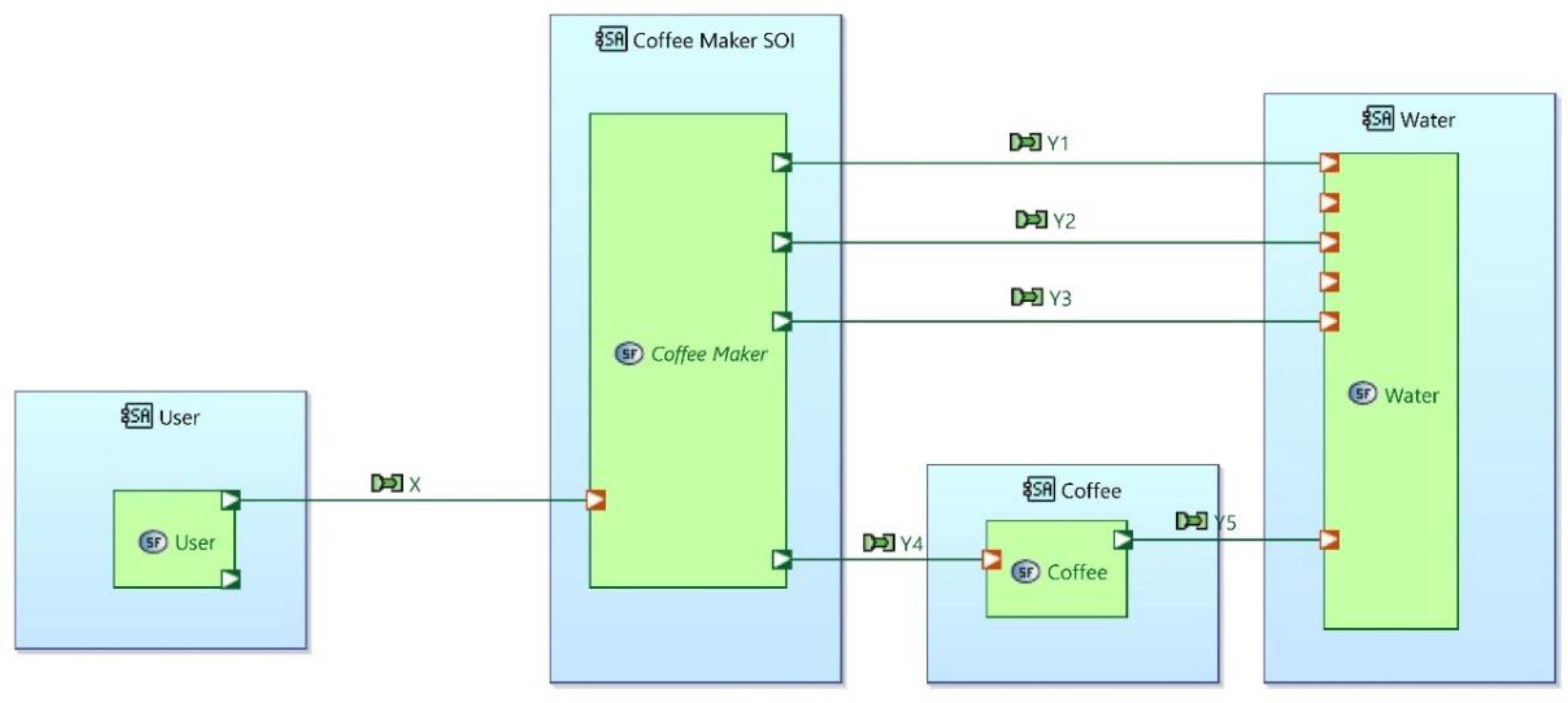
Figure 8.
Trial Decomposition.
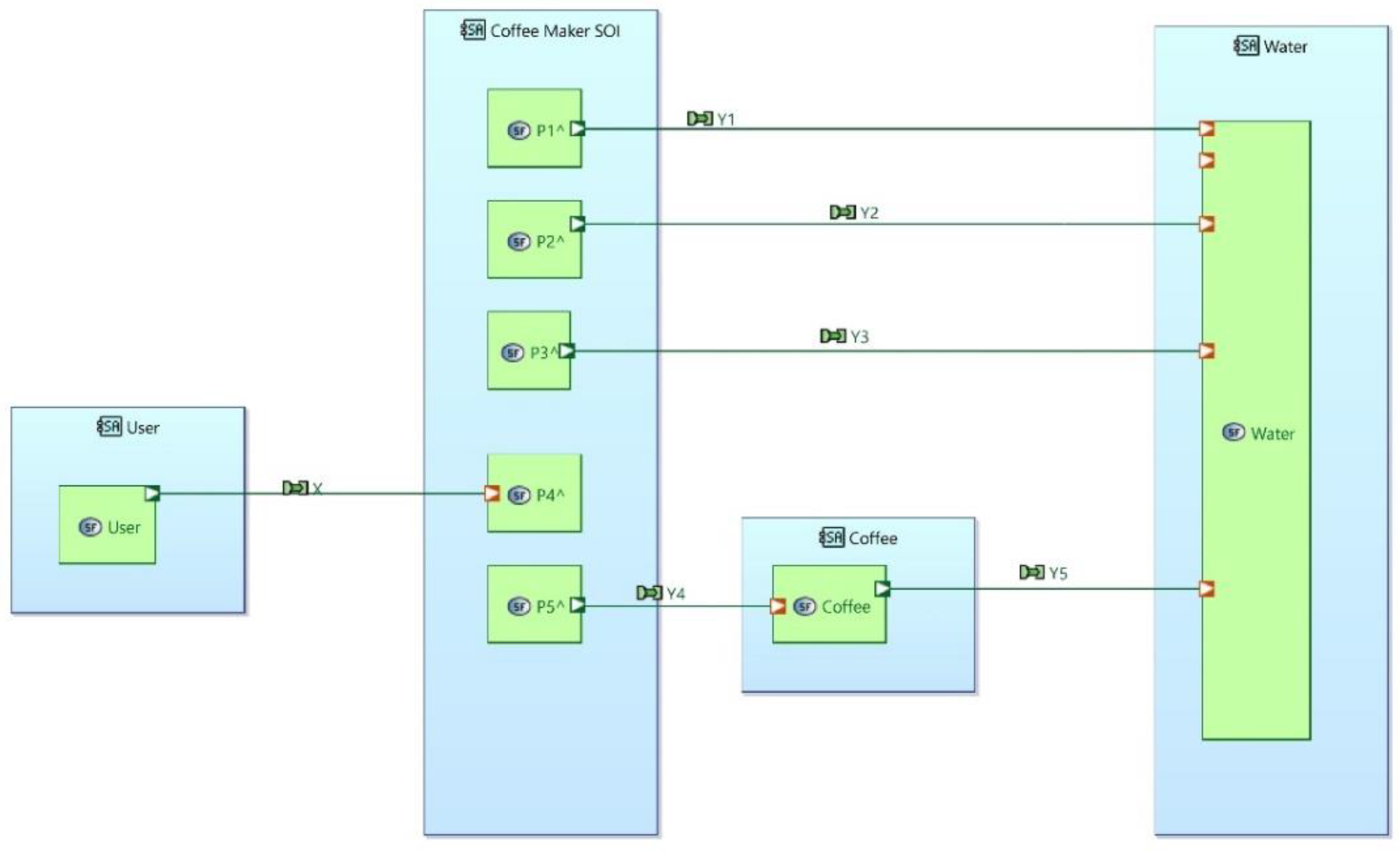
This results in the following subfunctions:
Here the are the previously quantified actions, is an unspecified action, is the specified reaction, the are unknown reactions.
Allocation of System Subfunctions to Components
We now attempt to find parts (components) with these functional behaviours:
supports an action to contain water. Any suitable container has this action. The size of the container can be determined by refining the user requirement to specify the quantity of coffee to be produced. is the reaction that supports this containment action – this is the force supporting the weight of the container provided by the surface it is resting on.
acts on the contained water through to heat it up. We consider possible off the shelf parts that provide the required interaction – i.e. that cause the water to be heated. Possible solutions include an electric heating coil, a gas heater or a microwave. For simplicity we select an electrical heating element. In this case we know that is a potential difference applied to the element and therefore that:
where is the resistance of the element.
produces an action on the water to transfer it to be in contact with the coffee. This can be achieved in several ways, for example by using steam pressure to move the water, or by just pouring the water, or perhaps the use of a pump.
reacts to a lever being pressed by making the coffee machine active. To embody this we need a component that takes as an input an electrical potential, and acts to provide a potential of when the lever is up and , when it is down.. When connected to this will cause the water to heat up. The obvious candidate is a simple switch.
is simply the behaviour of a container for the coffee.
This analysis outlines the proposed approach. Many details remain to be further analysed, such as the mechanism for controlling the temperature of the water used to brew the coffee. These fundamentals are illustrated:
- The statement of User Requirements in terms of changes to the environment that the system is required to accomplish,
- The identification of the interactions that are required to cause those changes, based on a quantitative analysis of the behaviour of the targets’ reaction to the system’s action.
- The identification of components able to provide the required actions and reactions
Discussion
In this paper, we re-evaluated a number of standard assumptions regarding the process of functional decomposition and have proposed a number of departures from the existing approach.
In particular, we have proposed to base the analysis on the changes to the environment that the system is required to make and the system interactions that cause those changes. This gives a more precise perspective than the simpler input/output view and allows us to accommodate interactions such as those involving fields that cannot be expressed in input/output terms.
Since the effects of the interactions apply to elements outside the system, we are proposing that the restriction of the analysis to the system boundary be reconsidered. We have given a number of examples where the reduction to a simple input/output view can force premature design decisions. The retention of information about the system’s immediate environment allows a better optimisation of the interaction between the system and the environment.
We also addressed the concept of function in Systems Engineering which at present is defined rather loosely. We have proposed a precise mathematical definition as a functional that relates the history of the reactions of the system to its actions. This unifies various existing approaches such as Wymore’s, DEVS and Linear Systems Theory. We have shown how Linear Systems Theory integrates naturally with our approach and have given examples of its application. We have found that the system’s external interactions take effect through boundary functions, and that the selection of parts to fulfil those functions is aided by a knowledge of the required effects of the actions on the environment resulting from the reactions to the environment.
Conclusion
We have developed a formal mathematical model of the process of functional decomposition for physical systems and have shown how it can provide a link between User Functional Requirements and the selection of parts which can form a system that satisfies the User Functional Requirements.
The model also shows how to incorporate DEVS modelling and Linear Systems Theory as a natural consequence of the analysis process. The design process follows a series of logical analytical steps and therefore should be straightforward to automate, resulting in a digital twin of the system to be constructed.
We conclude that the interaction view proposed by this paper serves to unify and formalise and extend a number of existing approaches to functional decomposition, leading eventually to the ability to fully automate the process of developing a digital twin of the required system and ultimately the construction of the system itself.
References
- W. Wymore, Model-Based Systems Engineering. 2018. [CrossRef]
- INCOSE, Systems Engineering Handbook, 4th ed. San Diego: Wiley, 2015.
- ‘Overview of the Systems Engineering Design Process’, in The Engineering Design of Systems, John Wiley & Sons, Ltd, 2009, ch. 2, pp. 49–72. [CrossRef]
- Salado, ‘A systems-theoretic articulation of stakeholder needs and system requirements’, Systems Engineering, vol. 24, no. 2, 2021. [CrossRef]
- L. von Bertallanfy, General system theory: Essays on its foundation and development. 1968.
- Y. Lin, General Systems Theory: A mathematical approach, vol. 12. Springer Science and Business Media, 2006.
- ISO, ‘ISO/IEC/IEEE International Standard - Systems and software engineering -- Life cycle processes -- Requirements engineering’, 2018.
- ‘Functional Architecture Development’, in The Engineering Design of Systems, John Wiley & Sons, Ltd, 2009, ch. 7, pp. 211–251. [CrossRef]
- ‘IDEFØ – Function Modeling Method – IDEF’. Accessed: Aug. 14, 2025. [Online]. Available: https://www.idef.com/idefo-function_modeling_method/.
- J. A. Estefan, ‘Survey of Model-Based Systems Engineering (MBSE) Methodologies’, 2008.
- Kossiakoff, W. N. Sweet, S. J. Seymour, and S. M. Biemer, Systems Engineering Principles and Practice: Second Edition. 2011. [CrossRef]
- R. L. Williams and D. A. Lawrence, ‘State-Space Fundamentals’, in Linear State-Space Control Systems, 2007, pp. 48–107. [CrossRef]
- P. Zeigler, ‘Hierarchical, Modular Discrete-Event Modelling in an Object-Oriented Environment’, Simulation, vol. 49, no. 5, 1987. [CrossRef]
- Yang and W. Marquardt, ‘An ontological conceptualization of multiscale models’, Comput Chem Eng, vol. 33, no. 4, 2009. [CrossRef]
- M. Chen, Z. Lin, and Y. Shamash, Linear Systems Theory: A Structural Decomposition Approach. 2004.
- J. Craig Wrigley, ‘Requirements Decomposition using a Graphical method’, in SOSE 2020 - IEEE 15th International Conference of System of Systems Engineering, Proceedings, 2020. [CrossRef]
- ‘Capella | Open Source MBSE Tool’. Accessed: Aug. 04, 2025. [Online]. Available: https://mbse-capella.org/.
| 1 | The possible time-dependence of is suppressed for clarity. |
Figure 3.
Input/Output vs Interaction.
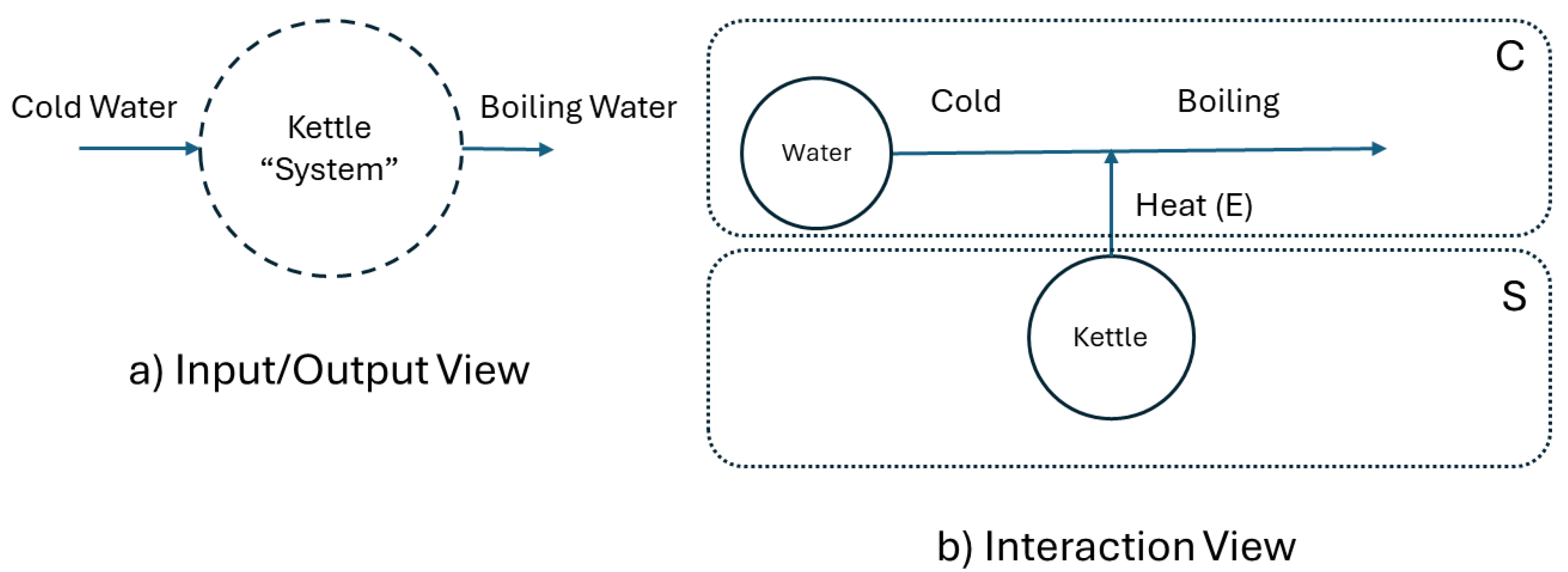
Figure 5.
User Requirements for Changes of State.
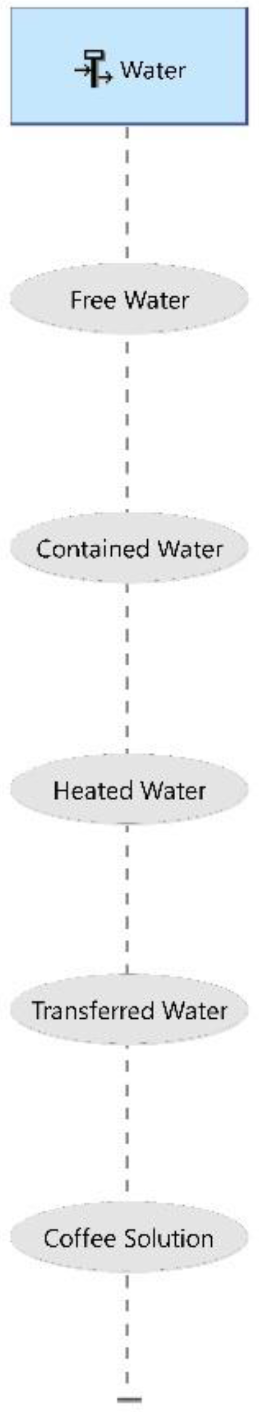
Figure 6.
Interactions of Coffee Maker.
Disclaimer/Publisher’s Note: The statements, opinions and data contained in all publications are solely those of the individual author(s) and contributor(s) and not of MDPI and/or the editor(s). MDPI and/or the editor(s) disclaim responsibility for any injury to people or property resulting from any ideas, methods, instructions or products referred to in the content. |
© 2025 by the authors. Licensee MDPI, Basel, Switzerland. This article is an open access article distributed under the terms and conditions of the Creative Commons Attribution (CC BY) license (http://creativecommons.org/licenses/by/4.0/).
Copyright: This open access article is published under a Creative Commons CC BY 4.0 license, which permit the free download, distribution, and reuse, provided that the author and preprint are cited in any reuse.


