
Submitted:
21 October 2025
Posted:
21 October 2025
You are already at the latest version
Abstract
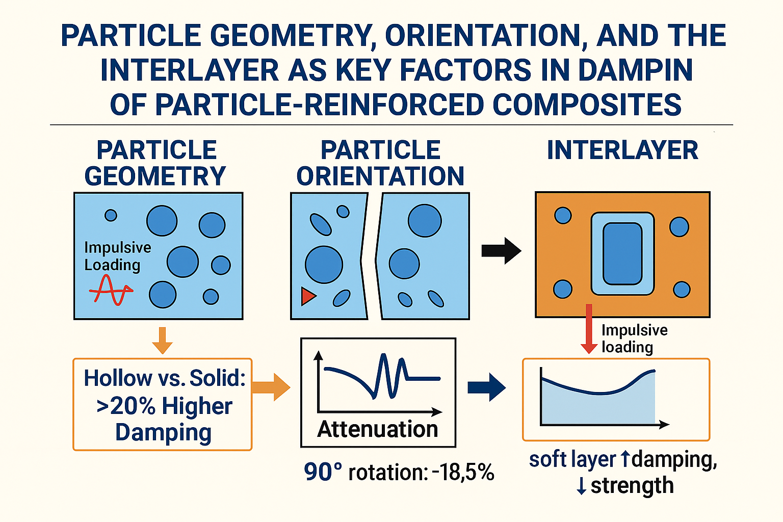
This study investigates, at the microscale, how particle geometry, orientation, and the interfacial layer affect stress-wave attenuation in particle-reinforced composites de-signed for dynamically loaded components. Representative unit cells with different particle shapes (circular, elliptical, rectangular, annular, and hollow) were modeled in ABAQUS using the explicit finite element analysis. The simulated impulse loading enabled the observation of stress-wave propagation and scattering within the polymer matrix. The results revealed that the presence of reinforcing particles—particularly their shape and the interfacial layer—has a significant influence on wave attenuation. Hollow particles consistently exhibited higher attenuation compared to solid ones. The hollow rectangular particles being the most effective, improving attenuation by more than 20 %. These findings highlight the critical role of microscale morphology in designing com-posite materials with optimized dynamic properties and provide recommendations for engineering applications requiring efficient vibration amplitude suppression.
Keywords:
particle-reinforced composites
; microscale
; stress-wave
; attenuation
; explicit fea
; impulsive loading
1. Introduction
In modern manufacturing and technological systems, mechanical components are increasingly designed to operate at higher speeds, power levels, and loading frequencies. This trend leads to elevated dynamic stresses in structures, often manifested in undesirable vibrations and increased deformability of mechanical systems. Excessive oscillations negatively affect the accuracy of manufacturing processes, the reliability of operation, and the service life of both individual components and entire devices. Reducing vibration amplitudes and efficiently dissipating mechanical energy represent key challenges in the design of advanced engineering systems. One promising strategy for mitigating dynamic effects is the use of composite materials, which exhibit a higher degree of intrinsic material damping compared to conventional materials. This property arises from the combined action of the elastic matrix, reinforcing particles or fibers, and interfacial interactions among the composite’s constituents.
Optimising the microstructure of a composite material can enhance its dynamic properties without significantly increasing weight or macro-structural complexity. The study presented in [1] stated that the optimal heterogeneous distribution of the core in a structural layered sandwich composite can nearly triple its stability compared to a homogeneous distribution. Thus, the optimised core, as a decisive factor of the sandwich microstructure, improved the static properties by up to 200 % under static loading.
However, damping is not solely an intrinsic property of the material; it also depends on several factors, such as temperature, dynamic loading frequency and amplitude, material anisotropy, and the physical characteristics of the individual components.
For the effective design of composite structures, it is essential to understand the mechanisms of vibration transmission and dissipation at the micro-level. In particle-reinforced composites, the geometric and distributional parameters of the reinforcing particles—such as their shape, size, spatial arrangement, and interaction with the matrix — play a crucial role. By altering the topology of the composite particles, it is possible to significantly influence the direction of stress-wave propagation and the rate of attenuation. For instance, hollow or annular particles provide additional interfaces where mechanical energy is scattered, thereby enhancing damping efficiency. This microscale structural variability enables designers to tailor composite materials with properties optimized for the specific dynamic requirements of their applications.
In recent years, it has become evident that traditional macroscopic approaches are insufficient to fully capture the phenomena associated with stress-wave propagation and damping in composite materials. Consequently, multi-scale modeling strategies, incorporating meso-, micro-, and nano-scale representations of the material structure, are increasingly employed. These approaches utilize numerical methods, primarily the finite element method (FEM), to simulate the dynamic behavior of composites. Explicit dynamic analyses, performed for example in the ABAQUS environment, enable a detailed examination of stress-wave propagation in representative unit cells with various reinforcing particle topologies. Such simulations provide valuable insights into the ability of specific microstructures to absorb and scatter mechanical energy, thereby contributing to the design of composites with optimized damping properties. An integrated numerical approach thus serves as an effective tool for identifying structures that exhibit reduced stress-wave amplitudes and enhanced energy dissipation.
The article analyzes stress-wave propagation in particle-reinforced composites at the microscale. Using explicit finite element analysis, various cross-sectional shapes of the reinforcing particles—circle, ellipse, rectangle, and their hollow counterparts (hollow circle, hollow ellipse, and hollow rectangle)—are modeled within a polymer matrix. Simulated impulsive compressive loading generates a stress wave, and its attenuation at the wavefront over time is monitored. Stress-wave attenuation can be considered a manifestation of the material’s intrinsic damping and of the composite topology’s ability to dissipate mechanical energy.
The primary objective of this study is to provide a detailed analysis of the influence of reinforcing particle geometry, their orientation relative to the prevailing load, and the effect of the interfacial layer on the vibrational and damping characteristics of particle-reinforced composites. Current research in the design of composite materials for dynamically loaded applications highlights the need for an integrated approach, encompassing the identification of vibration sources, quantification of material damping, and systematic investigation of the morphology of reinforcing components. The study presented in this article offers new insights and recommendations for the effective design of reinforcing particles, visualising the propagation of stress waves within the composite microstructure over time through detailed numerical model analyses. The proposed recommendations align with current trends and findings in the published literature, thereby significantly contributing to a deeper understanding of the relationship between the microstructure of composite materials and their macro-scale dynamic mechanical properties.
2. Theoretical Foundations of Vibrational Damping in Composite Materials
According to Bendat and Piersol [2], the primary macroscopic manifestation of damping in structural materials is the dissipation, or loss, of mechanical energy in vibrating elements of a mechanical system. The presence and intensity of damping can be quantified using a hysteresis loop (see Figure 1), which allows for the identification of the type of damping and the determination of the amount of mechanical energy lost from the system. This approach is typical for homogeneous viscoelastic or anelastic materials, where energy is converted into heat during cyclic loading.
In our numerical models, both the matrix and the particles were considered ideally elastic; therefore, the stress-wave attenuation observed in the simulations is caused solely by wave scattering and interference, representing an effective form of mechanical energy dissipation induced by microscale structural heterogeneity. The amount of mechanical energy lost from the system during a single loading cycle can generally be quantified via the area of the hysteresis loop. The area enclosed by the hysteresis loop in this work serves solely as an illustration of the general principle of damping. The energy loss coefficient, or the relative damping factor Ψ, is defined as the ratio of the area of the hysteresis loop (representing the energy loss ΔWd during one cycle) to the area under the loading curve and the x-axis, corresponding to the maximum strain energy W during one cycle.
The energy loss in a loaded material system during a single cycle can be expressed using a line integral:
where σ is the stress and ε represents the strain developed in the loaded system.
Internal (material) damping arises from the anelasticity of the material itself. Mechanical energy is converted into heat due to microplastic deformations and random microstructural defects, such as dislocations or microcracks. Energy loss is typically modeled using a hysteresis loop, where the damping force is proportional to the velocity and the natural frequency of vibration. It is commonly represented as:
Material behavior can also be expressed using a complex stiffness, which combines the elastic component of stiffness with an imaginary component representing damping:
where k is stiffness, η is material loss factor (damping factor), and x is displacement.
In composite materials, internal damping arises from their complex internal structure and the combination of constituent materials. In addition to conventional fiber- and particle-reinforced composites, there are structured composites such as laminates, sandwich panels, or hybrids. These materials are characterized by specific internal reinforcement arrangements (disposition and topology), which may include cellular structures, pores, or lattices. Parameters that significantly influence the mechanical and dynamic properties of a composite include layer orientation, fiber volume fraction, number and thickness of layers, layer sequence, and the composition of both fibers and matrix.
The damping mechanisms of polymer composites, however, are not limited solely to the viscoelasticity of the matrix; a significant contribution to energy dissipation also originates from the following phenomena:
- Internal damping through fillers – various types of particles or reinforcing fibers absorb mechanical energy through their own deformation or viscoelastic relaxation.
- Interfacial slip at the matrix–filler interface – interactions between the matrix and the filler allow microscopic slips that convert mechanical energy into heat. This effect is influenced by the type, size, shape, surface treatment, and volume fraction of the particles.
In addition to material parameters (stiffness, density, hardness), damping is largely determined by the geometric and topological characteristics of the reinforcement and their arrangement. Effective damping requires a proper combination of the matrix, the reinforcement, and their interface.
2.1. Multiscale Modeling – Hierarchical Arrangement
A detailed understanding of the dynamic behavior of composites requires the application of multiscale modeling.
Macroscale:
Macro-scale methods are based on phenomenological models and experimental data; they are capable of describing the overall behavior of the entire laminate but cannot capture local effects of reinforcement, such as fiber damage or stress-wave scattering. For this reason, three smaller scales—meso-, micro-, and nano-levels—have been introduced. These are often combined with the finite element method, enabling a link between structural parameters and resulting properties [4].
Mesoscale:
At the meso-scale, the composite is considered a two-phase system consisting of fiber bundles or clusters of particles embedded in the matrix. Structures at this scale are larger than microstructures but smaller than macrostructures (typically ranging from millimeters to centimeters). Mesoscale analysis is used to compare the behavior of different composite layers under dynamic loading, as each layer may have a distinct reinforcement orientation [5].
Microscale:
At the microscale, the focus is on the unit cell, the smallest repeating element of the composite that represents its microstructure. In terms of vibration damping, the interaction of propagating stress waves with the reinforcement is crucial: as the waves travel through the material, they encounter particles or fibers, and their scattering and interference cause attenuation. An important aspect is the accurate constitutive modeling of both the matrix and the reinforcement, as well as the consideration of the spatial arrangement of the reinforcement [6,7].
Nanoscale:
At the nanoscale, composites with nanoparticles, such as carbon nanotubes or nanofibers, are studied. Their high aspect ratio and large interfacial area enable intensive interfacial slip, which leads to effective frictional energy dissipation. As a result, nanocomposites exhibit exceptional damping capabilities, provided that the representative volume is properly defined and the orientation and volume fraction of the nano-reinforcement are carefully designed. Specialized methods, such as Dynamic Mechanical Thermal Analysis (DMTA) or resonance frequency analysis, are used for their characterization [8,9].
Figure 2 shows the hierarchical subdivision of multiscale analysis for a composite. The figure illustrates the transition from a macroscopic view of the entire laminate to microscopic and nanometric representations of the reinforcement, with each scale analyzing different characteristics of the structure and material behavior.
Effective vibration damping in composite structures thus depends on a complex combination of material composition, reinforcement topology, and the degree of interactions at the reinforcement–matrix interface. Internal damping is provided by the viscoelasticity of the polymer matrix as well as additional mechanisms, such as filler slip or interfacial sliding. To enable the design of composites with optimized damping performance, hierarchical multiscale methods are employed, linking macroscopic behavior with structural details at the meso-, micro-, and nano-scales. These tools allow for the prediction of dynamic response, identification of dominant damping mechanisms, and the design of suitable reinforcement topologies for specific applications.
3. Review of Published Works in the Field of the Studied Problem
In recent decades, research on composite materials with a focus on their dynamic behavior has expanded significantly, with particular attention given to the mechanisms of mechanical energy propagation and dissipation in heterogeneous structures. Several studies highlight the importance of microstructural parameters, such as the shape, size, orientation, and distribution of reinforcing particles, influencing the damping properties of composites. In the published work [11], the authors created 2D representative cells with circular, elliptical, and short-fiber particles, in which they simulated impulse wave propagation using the explicit finite element method. The stress-wave amplitude gradually decreased due to interactions with the microstructure, and attenuation was evaluated based on the reduction of von Mises stress. The study demonstrated that a 3.5 % fraction of circular particles increased wave attenuation to 40–43 % (the homogeneous matrix exhibited attenuation of ~12.5 %) and that the topology of the particle arrangement could further enhance attenuation by up to 15.3 %.
In the work [12], a mathematical model of damping in layered fiber-reinforced composites was developed and experimentally validated. The authors investigated the effects of fiber volume fraction, layer thickness, and reinforcement orientation on the damping ratio and dynamic response under sinusoidal excitation. Comparison of the calculated and measured time histories of the dynamic response showed that the proposed model accurately predicts the composite behavior. The study also demonstrates that increasing the reinforcement fraction and applying appropriate layer sequencing can effectively influence damping.
The work [13] addresses harmful torsional resonances in high-speed rotor bearings and proposes the use of composite inserts with carbon micro- and nanofibers shaped into honeycomb macrostructures. Resonance attenuation was achieved through the hierarchical microstructure and hollow cavities; at a frequency of approximately 2100 Hz, the average and maximum torsional amplitudes were reduced by 33 % and 43 %, respectively. The authors visualized the propagation of the stress wave at the micro-scale using explicit FE analysis, identifying wave dispersion along the fibers as the source of high damping.
The authors of work [14] describe the development of the explicit D-FE2 method, which enables simultaneous modeling of macro- and micro-scales in dynamic problems. The new algorithm is based on explicit integration within representative unit cells and was validated on examples including stress-wave propagation in porous materials, impact testing of honeycomb structures, and damage in fiber-reinforced composites. The results confirmed that the explicit D-FE2 method is effective for simulating transient dynamic phenomena and provides accurate solutions for problems involving large deformations.
The article [15] presents a comprehensive experimental investigation into the effectiveness of multi-unit particle dampers (MUPDs) applied to a cantilever structure subjected to harmonic and random dynamic excitation. The cantilever was selected as a model platform due to its significantly amplified response near resonance, particularly at the free end. Under extreme acceleration conditions, the maximum measured acceleration exceeded 50 times the gravitational acceleration. The study systematically examines key parameters influencing damping efficiency, including cavity geometry, orientation relative to the vibration direction, and the size and number of particles within the damper. Experimental results demonstrate that even with a minimal mass penalty—up to 8.8 % of the primary structure’s mass—the MUPD system can reduce resonance amplitude by more than 50 % under both sinusoidal and random excitation. Furthermore, optimization of cavity configuration and particle distribution significantly enhances the system’s capacity to absorb mechanical energy, especially in high-acceleration environments. These findings contribute to the advancement of passive damping technologies designed for extreme dynamic applications.
The work [16] numerically analyzes the propagation of a laser-induced pressure wave in three-dimensionally woven carbon composites using detailed and homogenized FE models. The authors investigated whether a detailed model could be replaced by a homogenized one. It was found that the geometric architecture significantly influences the rear-surface velocity profile and that homogenized models fail to accurately reproduce the pressure wave. Additionally, the detailed model predicted crack initiation in resin-rich regions, whereas the homogenized model could not capture fiber failure.
The study presented in work [17] investigates the dynamic response of multi-layer floors with a damping layer. The model is based on three-dimensional laminate theory and Chebyshev polynomials. The authors demonstrated that, under multi-source excitation, the dynamic response decreases with increasing thickness and elastic modulus of the damping layer, and that the position and trajectory of the moving load significantly affect the vibration amplitude.
Works [18,19,20,21] share a focus on reducing vibrations and improving the dynamic response of complex composite systems through appropriate modification of their internal structure. Research on 3D-printed composites showed that arranging Kevlar and glass fiber reinforcements at angles of 45°, 90°, and ±45° significantly enhances damping capacity, whereas the orientation of carbon fibers at 0° or 0°/90° reduces damping. Jalgarová et al. [19] demonstrated that epoxy–cement composites with an optimal amount of nano SiO₂ and graphene exhibit 92 % higher compressive strength and 38 % higher damping factor than conventional cement mixtures. Raza and co-authors [20] simulated and experimentally validated the vibration response of additively manufactured PLA composites with fiber reinforcement, finding that the 0°–0° orientation provides the highest natural frequencies and, when combined with MFC piezoelectric actuators, significantly enhances active damping. Murčinková et al. [21] showed that integrating composites filled with carbon powder, hollow glass microspheres, and sand into the bearing housings of high-speed rotating machinery can reduce the resonance peak by 30–70 %. All of these studies demonstrate that the appropriate combination of reinforcement materials, nanoparticles, and design modifications can effectively suppress resonances and ensure improved dynamic response in composite systems.
4. Methodology of Numerical Simulation of Composite Structures
The microscale analysis of particle-reinforced composites was conducted in ABAQUS/CAE. The matrix material, with a density of 1,200 kg·m⁻³ and a tensile modulus of 2.4 GPa, was reinforced with discrete particles of various shapes (circular, elliptical, rectangular). These particles were oriented either parallel or perpendicular to the direction of the impulse loading. The density and tensile modulus of the reinforcing particles were chosen to be twice that of the matrix. To analyze the dynamic response under impact loading, two-dimensional models of Representative Unit Cells (RUCs) were created to capture the repeating microgeometry of the composite. Using the explicit finite element analysis, the propagation of a stress wave induced by a unit impulse was simulated, and the time histories of Mises stress were evaluated at monitoring points. Attenuation was quantified based on the rate of amplitude decay of this stress wave—the greater the decay, the higher the damping.
The impulse load (see Figure 3a) was modeled as a pressure pulse acting perpendicular to the top edge of the model. The pressure increased linearly from 0 MPa to 10 MPa and then returned to zero over 2×10⁻⁷ s, creating a short but intense stress impulse.
After the impulse was applied, the stress wave began propagating from the impact location, i.e., the top edge. The degree of freedom in the Y-direction was fixed at the bottom edge, and symmetry boundary conditions were applied on both vertical edges (see Figure 3b). The simulation was performed in 100 steps, with the total time interval of 1×10⁻⁵ s evenly divided into increments of 1×10⁻⁷ s. Under this setup, the time increment was at the stability limit of the calculation, indicating high accuracy and the relevance of the obtained results.
Figure 4 shows the individual RUC variants with different shapes of the reinforcing material. Since the RUC is 2D, the circle, ellipse, and rectangle represent the cross-sections of particles or fibers. The hollow circle, hollow ellipse, and hollow rectangle correspond to their hollow variants. The rectangle can also represent the cross-section of a short fiber with its axis in the plane of the RUC. The RUC in Figure 4f represents a short tubular fiber.
The presented numerical models can be modified by introducing a transition zone as a thin interphase between the stiffer particle and the softer matrix, representing a RUC with interphase at circular particle (Figure 4h). All representative unit cells containing a particle were compared with a reference model without a particle (Figure 4a and Figure 5a), i.e., an empty homogeneous matrix. In all cases, the same matrix-to-particle area ratio (Am:Aₚ) was maintained to ensure consistency of geometric parameters across the different models.
The finite element mesh (Figure 5) for RUC0, RUCcircle, RUCellipse, RUCrectangle, RUChollow circle, and RUChollow rectangle was composed of 4-node bilinear quadrilateral plane stress elements with reduced integration (CPS4R). The mesh density was set to 0.55 mm with a minimum curvature factor of 0.1 (10 %), resulting in 1,178 elements.
The initial numerical model shows the monitoring points (Figure 6), through which the stress is captured over time as the impulse wave propagates through the computational model. These points are used to evaluate the stress wave attenuation along three vertical lines (1–4, 5–8, 9–12) for all particle composite model configurations.
As described, the impulse pressure load applied to the top edge of the model generated a stress wave that propagated through the composite structure. Based on the values at the wavefront, i.e., the first maximum amplitude of the Mises stress at the monitoring points, the stress wave attenuation was calculated along three lines of monitoring points: 1–4, 5–8, and 9–12. The overall attenuation was determined as the average of the attenuations along lines 1–4, 5–8, and 9–12. The stress attenuation along each line of points is determined as follows:
where σMi is the value of the Mises stress at the wavefront of the propagating stress wave at the i-th monitoring point.
5. Analysis of the Influence of Particle Geometry and Orientation on Stress Wave Attenuation
For comparison of the stress wave attenuation simulation, Figure 7 shows the stress wave propagation phases for the particle-free simulation model as well. Wave propagation in the particle-free model is not affected by any interaction with stiffer reinforcing material or interfaces. The stress wave remains homogeneous. The RUC0 without a particle exhibits an attenuation of 12.5 %.
5.1. Mechanisms of Stress Wave Propagation and Scattering in Particle-Reinforced Composites
The application of an impulse load to the top edge of the particle-reinforced composite initiates the propagation of a stress wave in the vertical direction across the entire width of the model (Figure 8a). In the initial phase, the wave propagates without interacting with the reinforcing elements until it first contacts a particle. As shown in Figure 8b, upon reaching a stiffer particle, an interaction occurs between the wave and the particle, leading to a gradual reduction in stress amplitude (Figure 8c). As the wave continues to propagate through other regions of the composite material, a significant attenuation of the Mises stress at the wavefront is observed, with substantially lower stress values recorded at the final monitoring points (Figure 8d).
Recall that the numerical model included reinforcing particles with a Young’s modulus twice that of the base material (matrix). Figure 8, Figure 9, Figure 10, Figure 11 and Figure 12 illustrate the various phases of stress wave propagation through the composite structure with different particle geometries.
The influence of the interlayer on stress wave propagation depends on its properties. The interlayer can be stiffer or softer than the matrix, with ratios of Em:Einterlayer=1:0.2, 1:0.5, and 1:1.5. The final propagation phase can be compared for all three cases (Figure 13). For a softer interlayer (Figure 13a,b), the stress wave exhibits significantly greater scattering with visible numerous interactions, whereas a stiffer interlayer than the matrix results in only minor scattering (Figure 13c).
6. Interpretation of Numerical Results and Implications for Composite Design
The results clearly demonstrate that the geometric shape of the reinforcing particles has a significant impact on the stress wave attenuation in particle-reinforced composites. RUC models with hollow particles consistently exhibited higher attenuation compared to their solid counterparts, which can be attributed to more effective mechanical energy scattering due to altered particle stiffness, internal structure, and increased interfacial areas.
The highest attenuation among the models with solid particles was observed for the RUCcircle, where the overall attenuation reached 24.7 % (Fig. 15). Compared to the reference model without particles, RUC0, the attenuation with solid particles was nearly twice as high. Models with hollow particles demonstrated that the achieved attenuation values exceeded those of the solid particle models. The hollow circular particle, RUChollow circle, exhibited 7.3 % higher attenuation than the solid circular particle, RUCcircle. The hollow elliptical particle, RUChollow ellipse, showed an 11.0 % increase in attenuation compared to the solid elliptical particle. The most notable improvement was observed for the hollow rectangular particle, RUChollow rectangle, which achieved 20.6 % higher attenuation than its solid equivalent, RUCrectangle. By comparing the attenuation of RUCs with solid and hollow particles, it is indicated that the hollow core leads to a more significant dispersion of stress waves. This finding aligns with the assumption that shape anisotropies and internal cavities enhance the interaction between the wave and the reinforcing element.
Figure 14.
Stress wave attenuation for different particle shapes along three lines of points (1–12).
Figure 14.
Stress wave attenuation for different particle shapes along three lines of points (1–12).

Based on the attenuation analysis for different particle shapes, a numerical simulation was also performed for the case of vertically oriented particles in the matrix, representing a change in orientation relative to the loading direction. The results of the overall stress-wave attenuation for particles rotated by 90° clearly show that particle orientation significantly affects the attenuation level (Figure 15). When the solid elliptical particle, RUCellipse, was rotated, the total attenuation decreased by 3.1 %, whereas for the hollow elliptical particle, RUChollow ellipse, it dropped by 8.7 %. For the solid rectangular particle, RUCrectangle, attenuation decreased by 2.9 %, and for the rectangular particle with a longitudinal cavity, RUChollow rectangle, the decrease reached 18.5 %.
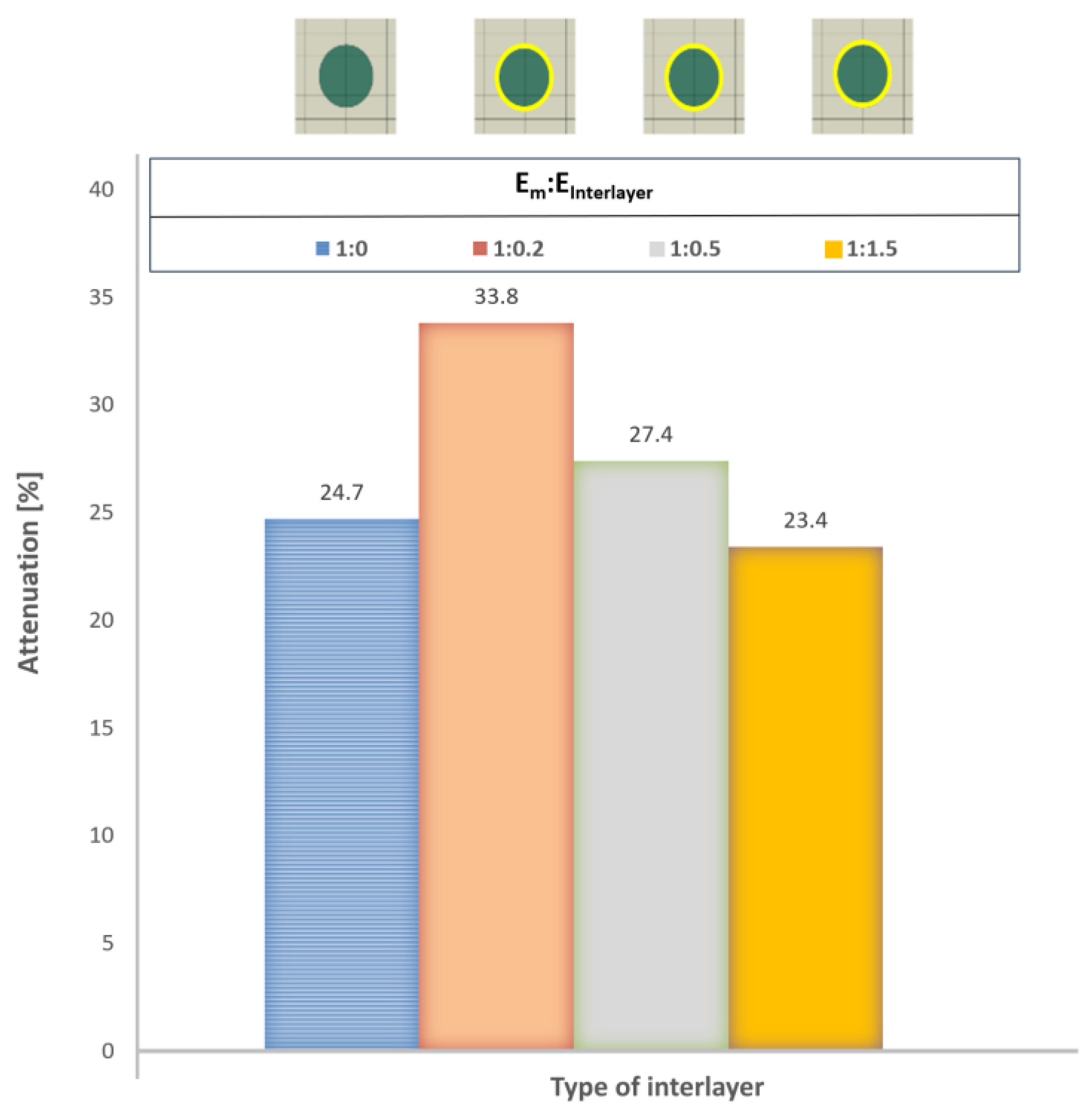
Although the interlayer is thin—on the order of micrometers to nanometers—it alters the mechanical properties and influences damping-related processes. A softer interlayer increases the amount of dissipated energy, resulting in an enhanced damping of approximately 10 % for the same interlayer thickness. It can be expected that a thicker, softer interlayer will further increase the damping (see Figure 16).
The numerical results presented in the previous sections clearly demonstrate that the geometric shape and orientation of reinforcing particles, as well as the presence of an interlayer, play a key role in the level of damping and the manner in which stress waves are scattered in particulate composites. This effect can be explained by a combination of mechanisms through which the stress wave, as a carrier of mechanical energy, propagates, changes direction, or is absorbed and dissipated:
- reflection, refraction, and scattering: When a stress wave reaches the particle–matrix interface, i.e. an interlayer during wave–particle or wave–interphase–particle interactions, part of its mechanical energy is dissipated, and the wave is redistributed in multiple directions across the composite’s material phases,
- wave interference: Partially reflected waves interact with one another, leading to mutual attenuation and a reduction in overall wave amplitude.
Hollow particles, as well as the presence of an interlayer, introduce multiple internal interfaces that markedly enhance the probability of interactions between the propagating stress wave and the internal topology of the composite.
The numerical simulations consistently revealed that hollow geometries exhibit superior damping performance compared to their solid equivalents. The most significant improvement was observed for the hollow rectangular particle, which demonstrated a 20.6 % higher attenuation than the solid rectangular configuration. These findings corroborate the hypothesis that the combined effect of particle geometry and internal cavities constitutes an effective design strategy for maximizing mechanical energy dissipation.
An important aspect is the orientation of the particles relative to the loading direction. A 90° rotation demonstrated that even for identical particle geometries, the attenuation can vary significantly (up to 18.5 % for the hollow rectangular particle). This finding highlights the necessity of controlled orientation of reinforcement elements during composite manufacturing, as random or unfavorable alignment may reduce the damping efficiency.
In addition, the presence of a compliant interlayer between the matrix and the particle further enhances damping. However, since a softer interlayer also decreases the overall strength of the composite, this approach to improving damping through soft interlayers is suitable only for components where structural strength is not critical and which are introduced primarily to serve as damping components in joints.
From the perspective of designing composites for dynamically loaded applications (e.g., rotating machinery subjected to non-harmonic excitations, load-bearing structures exposed to seismic effects, or components under impact loading), several recommendations can be drawn:
- Preference for hollow particles, which introduce multiple internal interfaces and enhance the scattering of mechanical energy.
- Optimization of particle orientation with respect to the dominant direction of stress wave propagation.
- Use of soft interlayers in components of minor structural significance, where strength is not critical and damping performance is prioritized.
The findings of this study carry broader implications for the design and optimization of advanced composites. They clearly demonstrate that the performance of a composite cannot be assessed solely on the basis of the volume fraction of its constituents; rather, the internal microscale structural topology plays a decisive role in controlling its dynamic response. This insight aligns with current directions in multiscale modeling, which highlight the governing influence of micro- and nanostructures on macroscopic behavior. Consequently, rational design strategies for dynamically loaded components should integrate not only material composition but also the tailored engineering of particle geometry, orientation, and interfacial architecture. Such an approach opens new opportunities for enhancing damping efficiency while preserving structural integrity in next-generation composite systems
It is important to emphasize the limitations of the performed simulations. The model was two-dimensional and assumed ideal adhesive bonding between the composite phases, which may not be fully satisfied under real conditions. Moreover, the simulations focused on impulse loading within a short time interval, whereas in practice, repeated dynamic excitations may occur. Future research in this field will be directed towards:
- 3D modeling with realistic interfacial conditions,
- experimental validation of the results through dynamic testing,
- analysis of frequency-dependent behavior and multi-cycle loading.
7. Conclusions
The presented study provides new insights into how the microscale structural arrangement of reinforcing particles influences the ability of particle-reinforced composites to dissipate mechanical energy. The analysis was based on numerical modeling and the results confirm that microstructural topology plays a crucial role in the design of materials intended for dynamic loading.
The most important contribution of this work lies in the methodological framework, which enables a systematic investigation of the effects of particle shape, orientation, and the presence of interlayers on the damping properties, without the need for demanding experiments in the early stages of material development. This approach establishes a foundation for the efficient optimization of composite design and reduces the risk of failure in practical applications
From a practical standpoint, the findings of this study provide valuable guidance for the design of lightweight structures with enhanced vibration resilience, a critical requirement in mechanical, automotive, and aerospace engineering, as well as in constructions subjected to seismic or impact loading. The numerical approach presented in this study also opens opportunities for investigating additional parameters, such as combined reinforcement geometries, various types of matrix materials, and particle–matrix interfacial interactions.
Overall, it can be concluded that appropriately selected geometry and orientation of the reinforcing particles and presence of an interlayer represent an effective means of enhancing the damping capacity of particle-reinforced composites without altering the material composition itself. This approach offers a promising pathway toward the design development of next-generation structural materials, capable of providing improved reliability, durability, and safety in dynamically loaded systems.
Author Contributions
Conceptualization, Z.M. and P.B.; methodology, D.S. and Z.M.; software, P.B.; validation, Z.M., D.S. and P.B.; formal analysis, Z.M. and D.S.; investigation, D.S.; resources, D.S.; data curation, Z.M and P.B.; writing—original draft preparation, Z.M. and D.S.; writing—review and editing, P.B.; visualization, P.B.; supervision, Z.M.; project administration, P.B.; funding acquisition, P.B. All authors have read and agreed to the published version of the manuscript.
Funding
The article was prepared thanks to the support of The Ministry of Education, Research, Development and Youth of the Slovak Republic through the grants KEGA number 052TUKE-4/2024 and KEGA number 009TUKE-4/2024 and the Slovak Research and Development Agency for supporting this research through grant number APVV-18-0316. The Article Processing Charge was funded by KEGA number 052TUKE-4/2024.
Data Availability Statement
The data presented in this study are available on request from the corresponding author. The data are not publicly available due to restrictions on funding sources.
Conflicts of Interest
The authors declare no conflicts of interest.
References
- Pozorski, Z.; Pozorska, J. Influence of the Heterogeneity of the Core Material on the Local Instability of a Sandwich Panel. Materials 2022, 15, 6687. [Google Scholar] [CrossRef] [PubMed]
- Bendat, J.S.; Piersol, A.G. Engineering Applications of Correlation and Spectral Analysis; Wiley: Hoboken, NJ, USA, 2013; ISBN 978-0-471-57055-4. [Google Scholar]
- Švinčák, J. Návrh zariadenia pre meranie tlmiacich vlastností konštrukčných materiálov. Diplomová práca, Slovenská technická univerzita v Bratislave – Materiálovotechnologická fakulta, Trnava, Slovensko, 2011.
- Chen, Y.; Zhang, J.; Li, Z.; et al. Intelligent Methods for Optimization Design of Lightweight Fiber-Reinforced Composite Structures: A Review and the State-of-the-Art. Sec. Polymeric and Composite Materials 2023, 10. [Google Scholar] [CrossRef]
- Drach, A.; Drach, B.; Tsukrov, I.; et al. Realistic FEA Modeling of 3D Woven Composites on Mesoscale. In Proceedings of the 19th International Conference on Composite Materials (ICCM19), 2013. Available online: https://www.researchgate.net/publication/267759044_Realistic_FEA_modeling_of_3D_woven_composites_on_mesoscale (accessed on day month year).
- Guo, Q.; Yao, W.; Li, W.; Gupta, N. Constitutive Models for the Structural Analysis of Composite Materials for the Finite Element Analysis: A Review of Recent Practices. Composite Structures 2021, 260, 113267. [Google Scholar] [CrossRef]
- Youchun, Z.; Chao, X.; Junhui, Y.; et al. Experimental and Modeling Studies of Stress Wave Propagation and Energy Dissipation Mechanism in Layered Composite Structures. Shock and Vibration 2021, 113, 13. [Google Scholar] [CrossRef]
- Jancar, J. Review of the Role of the Interphase in the Control of Composite Performance on Micro- and Nano-Length Scales. Journal of Materials Science 2008, 43, 6747–6757. [Google Scholar] [CrossRef]
- Latibari, S.T.; Mehrali, M.; Mottahedin, L.; et al. Investigation of Interfacial Damping Nanotube-Based Composite. Composite Part B: Engineering 2013, 50, 354–361. [Google Scholar] [CrossRef]
- Bostanabad, R.; Liang, B.; Gao, J.; et al. Uncertainty Quantification in Multiscale Simulation of Woven Fiber Composites. Comput. Methods Appl. Mech. Eng. 2018, 338, 506–532. [Google Scholar] [CrossRef]
- Sabol, D.; Murčinková, Z. Stress Wave Propagation and Decay Based on MicroScale Modelling in the Topology of Polymer Composite with Circular Particles. Polymers 2024, 16, 2189. [Google Scholar] [CrossRef] [PubMed]
- Cai, B.; Yao, Z.; Zhang, X.; Li, C.; Liu, X.; Zhang, C.; Wang, Z. Damping Model of Fiber Reinforced Composites and Factors Affecting Damping and Dynamic Response. Applied Composite Materials 2021, 28, 1451–1476. [Google Scholar] [CrossRef]
- Murčinková, Z.; Živčák, J.; Sabol, D. Torsional Vibrations in the Resonance of High-Speed Rotor Bearings Reduced by Dynamic Properties of Carbon Fiber Polymer Composites. Materials 2023, 16, 3324. [Google Scholar] [CrossRef] [PubMed]
- Liu, K.; Tian, L.; Gao, T.; Wang, Z.; Li, P. An Explicit DFE₂ Method for Transient Multiscale Analysis. International Journal of Mechanical Sciences 2025, 285, 109808. [Google Scholar] [CrossRef]
- Ye, H.; Wang, Y.; Liu, B.; Jiang, X. Experimental Study on the Damping Effect of Multi-Unit Particle Dampers Applied to Bracket Structure. Applied Sciences 2019, 9, 2912. [Google Scholar] [CrossRef]
- Tserpes, K.; Kormpos, P. Detailed Finite Element Models for the Simulation of the Laser Shock Wave Response of 3D Woven Composites. Journal of Composites Science 2024, 8, 83. [Google Scholar] [CrossRef]
- Sun, L.; Xu, T.; Tian, F.; Zhang, Y.; Zhao, H.; Mahmood, A.H. Study on Dynamic Response of Damping Type Composite Floor Slabs Considering Interlayer Interaction Influences. Journal of Composites Science 2025, 9, 57. [Google Scholar] [CrossRef]
- Michal, P.; Vaško, M.; Sapieta, M.; Majko, J.; Fiačan, J. The Impact of Internal Structure Changes on the Damping Properties of 3D-Printed Composite Material. Applied Sciences 2024, 14, 5701. [Google Scholar] [CrossRef]
- Jalgar, S.R.; Hunashyal, A.M.; Prabhu, U.S.; Gurumurthy, B.M.; Hiremath, P.; Naik, N. Dynamic Mechanical Analysis and Optimization of Vibration Damping in Epoxy-Based Nano Cement Composite Dampers for Sustainable Structures. Journal of Composites Science 2025, 9, 202. [Google Scholar] [CrossRef]
- Raza, A.; Mieloszyk, M.; Rimašauskienė, R.; Jūrėnas, V.; Maqsood, N.; Rimašauskas, M.; Kuncius, T. Dynamic Properties and Vibration Control of Additively Manufactured Carbon and Glass Fiber Reinforced Polymer Composites Using MFC: A Numerical Study with Experimental Validation. Journal of Manufacturing and Materials Processing 2025, 9, 235. [Google Scholar] [CrossRef]
- Murčinková, Z.; Adamčík, P.; Sabol, D. Dynamic Response of Components Containing Polymer Composites in the Resonance Region for Vibration Amplitudes up to 5 g. Polymers 2022, 14, 5051. [Google Scholar] [CrossRef] [PubMed]
Figure 1.
Material hysteresis loop under cyclic loading [3].
Figure 1.
Material hysteresis loop under cyclic loading [3].
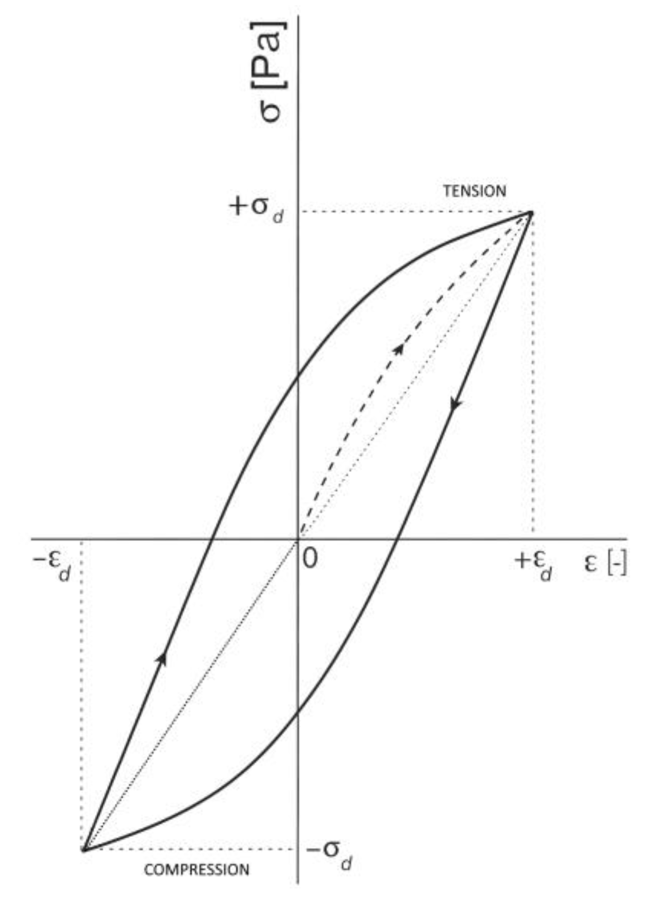
Figure 2.
Hierarchical subdivision of multiscale analysis for a composite [10].
Figure 2.
Hierarchical subdivision of multiscale analysis for a composite [10].
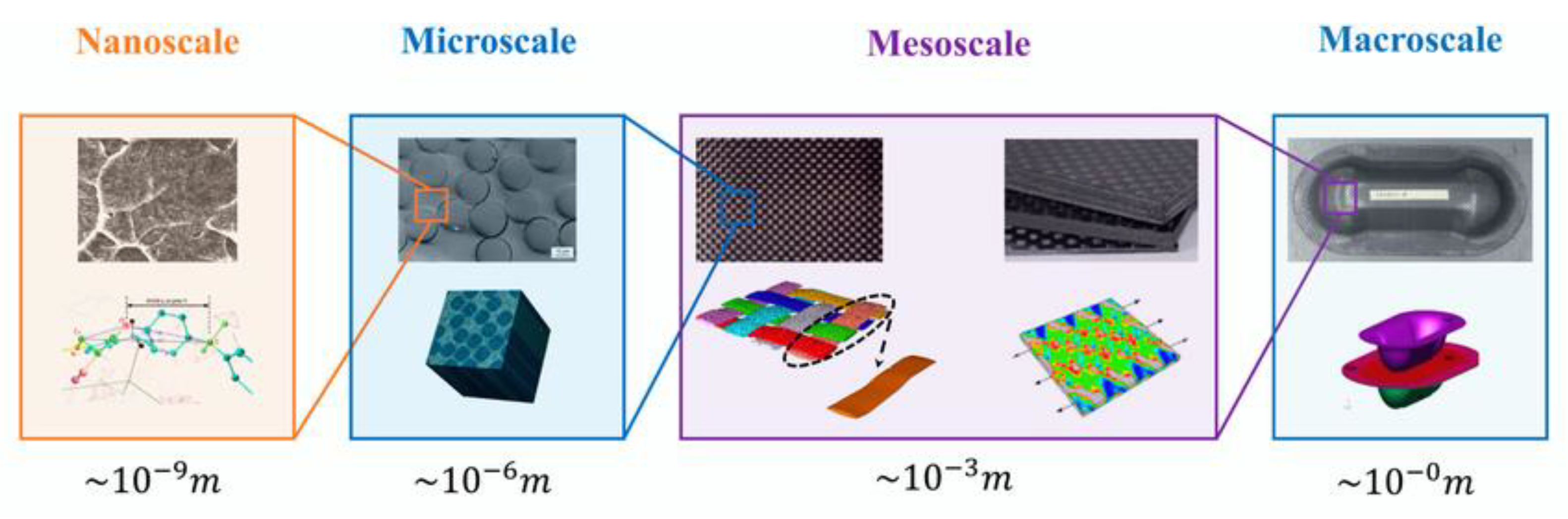
Figure 3.
(a) Impulse load, (b) Boundary conditions and model geometry.
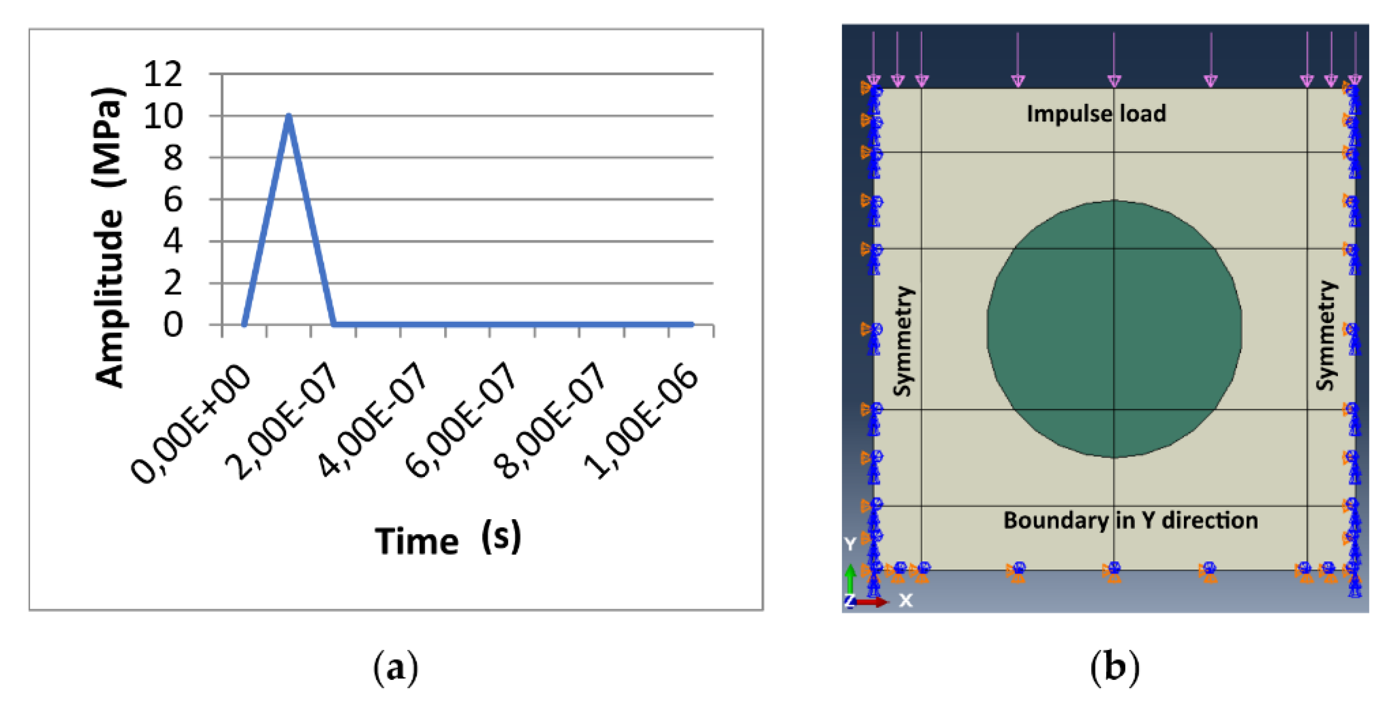
Figure 4.
RUCs with different particle shapes: (a) RUC0, i.e., particle-free model, (b) RUCcircle, (c) RUCellipse, (d) RUCrectangle, (e) RUChollow circle, (f) RUChollow rectangle, (g) RUChollow ellipse, (h) RUCinterlayer.
Figure 4.
RUCs with different particle shapes: (a) RUC0, i.e., particle-free model, (b) RUCcircle, (c) RUCellipse, (d) RUCrectangle, (e) RUChollow circle, (f) RUChollow rectangle, (g) RUChollow ellipse, (h) RUCinterlayer.
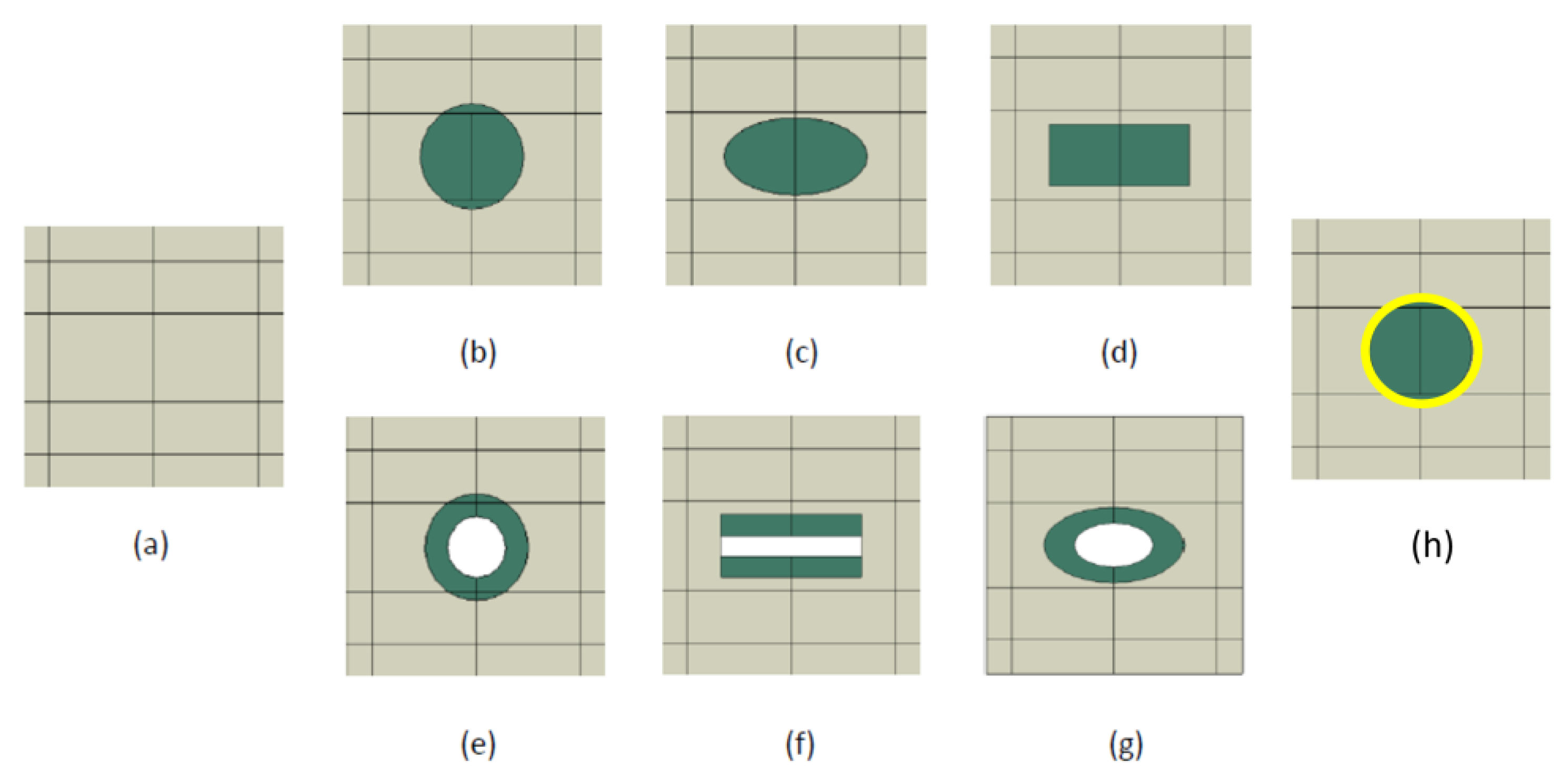
Figure 5.
Numerical models with finite element mesh (CPS4R): (a) RUC0, (b) RUCcircle, (c) RUCellipse, (d) RUCrectangle, (e) RUChollow circle, (f) RUChollow rectangle.
Figure 5.
Numerical models with finite element mesh (CPS4R): (a) RUC0, (b) RUCcircle, (c) RUCellipse, (d) RUCrectangle, (e) RUChollow circle, (f) RUChollow rectangle.
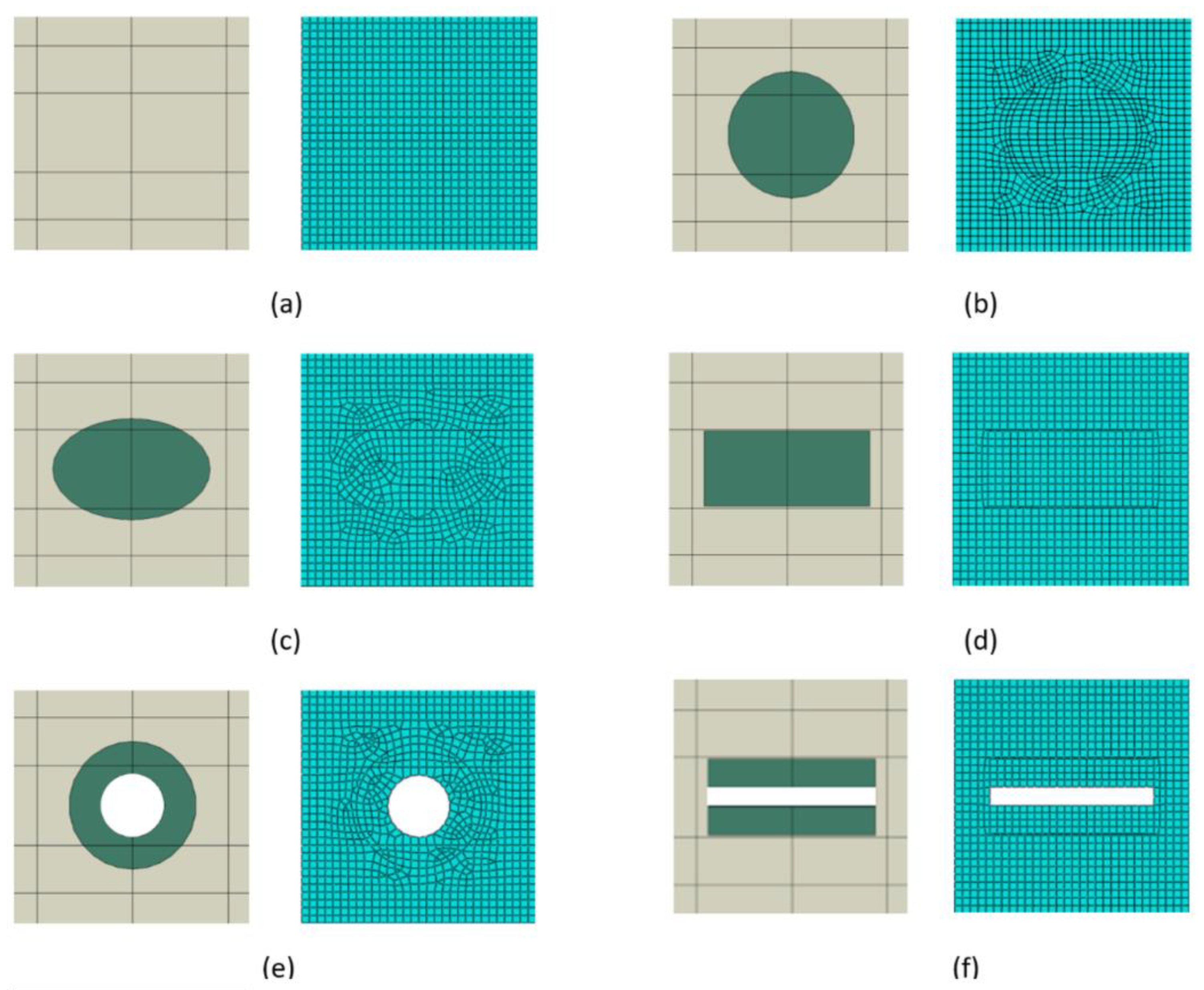
Figure 6.
Numerical model showing the location of monitoring points for stress wave attenuation evaluation.
Figure 6.
Numerical model showing the location of monitoring points for stress wave attenuation evaluation.
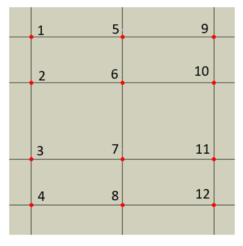
Figure 7.
Stress wave propagation phases in the particle-free model RUC0: (a) phase 1, (b) phase 2, (c) phase 3.
Figure 7.
Stress wave propagation phases in the particle-free model RUC0: (a) phase 1, (b) phase 2, (c) phase 3.
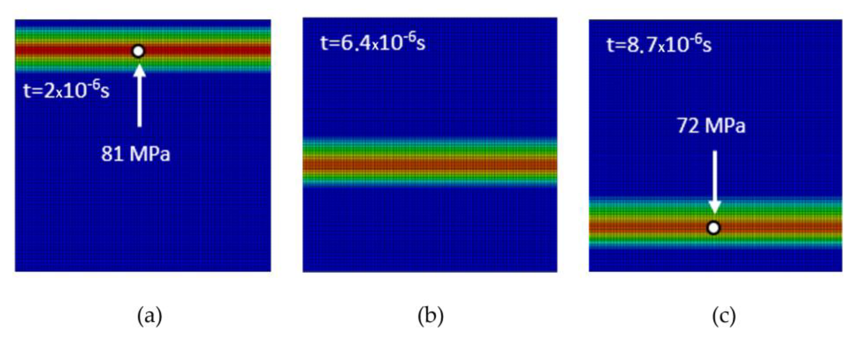
Figure 8.
Stress wave propagation phases for RUCrectangle: (a) phase 1, (b) phase 2, (c) phase 3, (d) phase 4.
Figure 8.
Stress wave propagation phases for RUCrectangle: (a) phase 1, (b) phase 2, (c) phase 3, (d) phase 4.
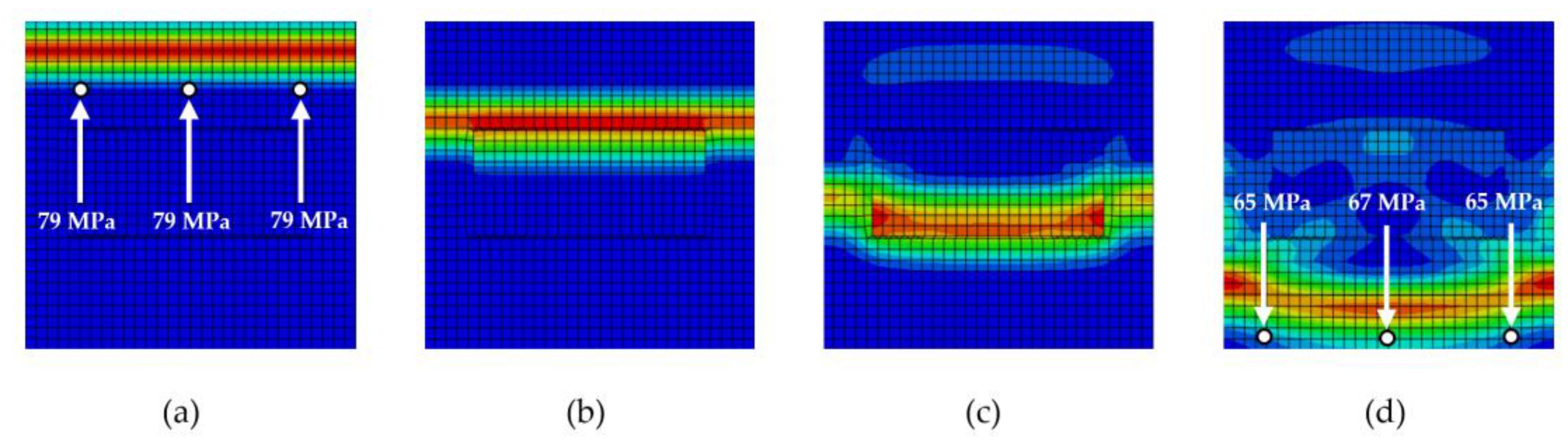
Figure 9.
Stress wave propagation phases for RUCellipse: (a) phase 1, (b) phase 2, (c) phase 3, (d) phase 4.
Figure 9.
Stress wave propagation phases for RUCellipse: (a) phase 1, (b) phase 2, (c) phase 3, (d) phase 4.
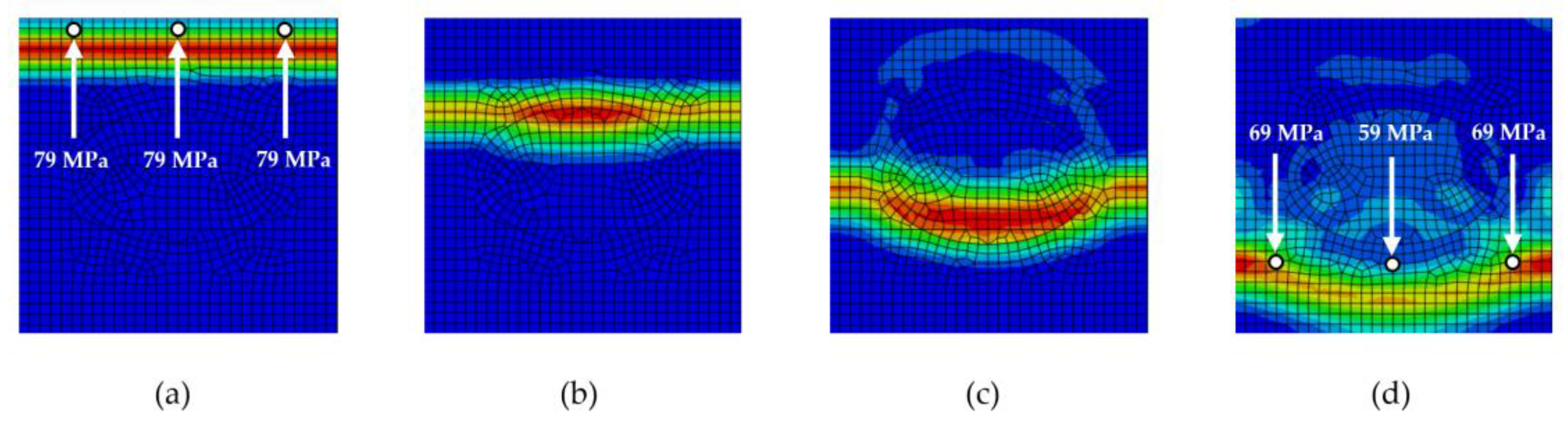
Figure 10.
Stress wave propagation phases for RUCcircle: (a) phase 1, (b) phase 2, (c) phase 3, (d) phase 4.
Figure 10.
Stress wave propagation phases for RUCcircle: (a) phase 1, (b) phase 2, (c) phase 3, (d) phase 4.
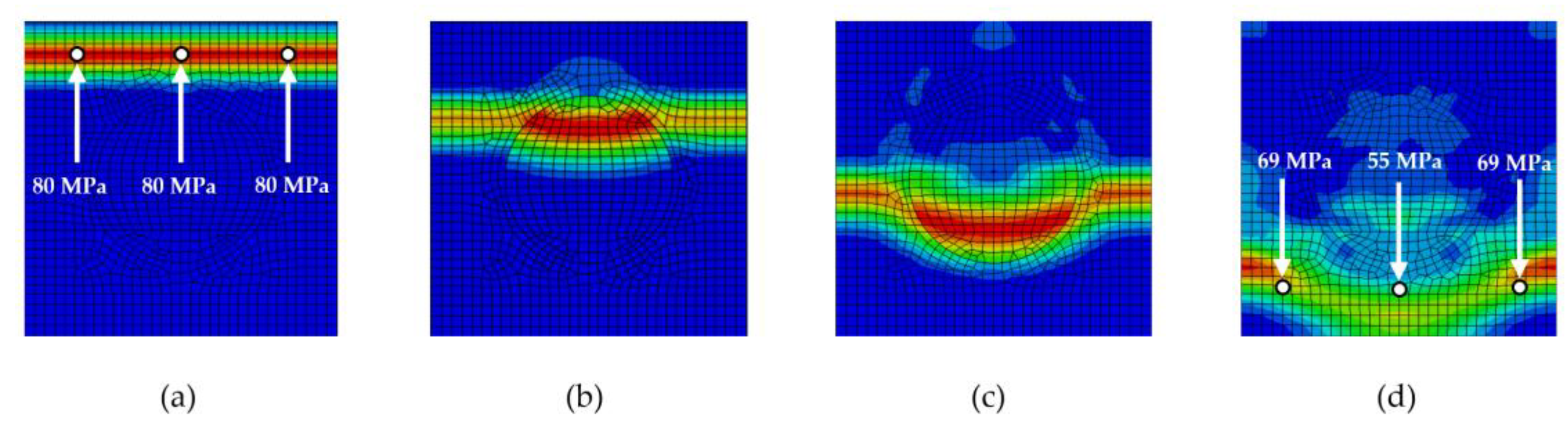
Figure 11.
Stress wave propagation phases for RUChollow circle: (a) phase 1, (b) phase 2, (c) phase 3, (d) phase 4.
Figure 11.
Stress wave propagation phases for RUChollow circle: (a) phase 1, (b) phase 2, (c) phase 3, (d) phase 4.
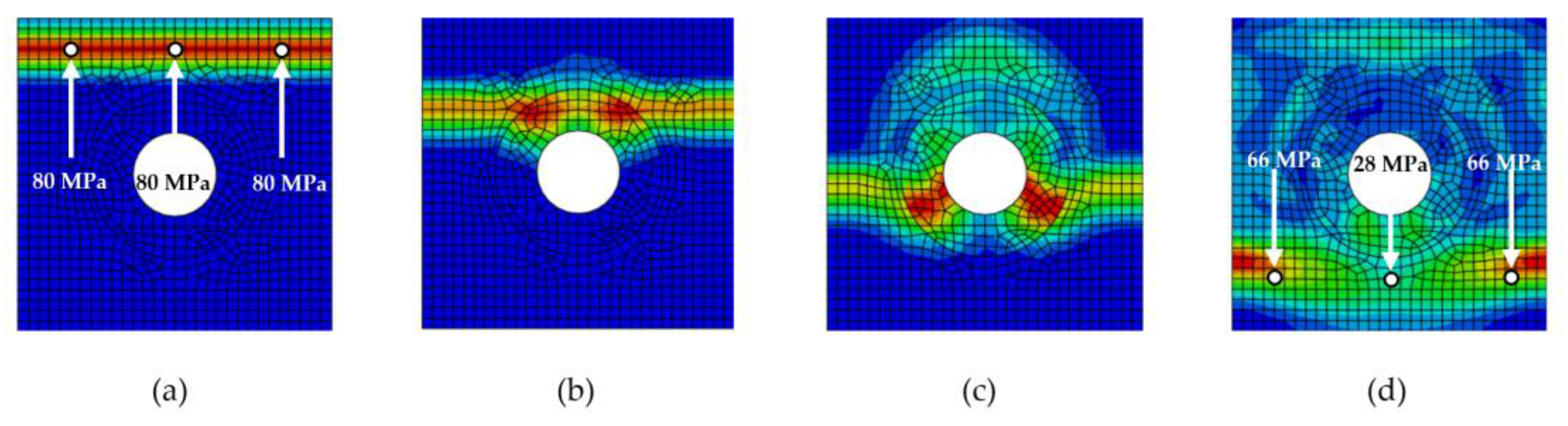
Figure 12.
Stress wave propagation phases for RUChollow rectangle: (a) phase 1, (b) phase 2, (c) phase 3, (d) phase 4.
Figure 12.
Stress wave propagation phases for RUChollow rectangle: (a) phase 1, (b) phase 2, (c) phase 3, (d) phase 4.
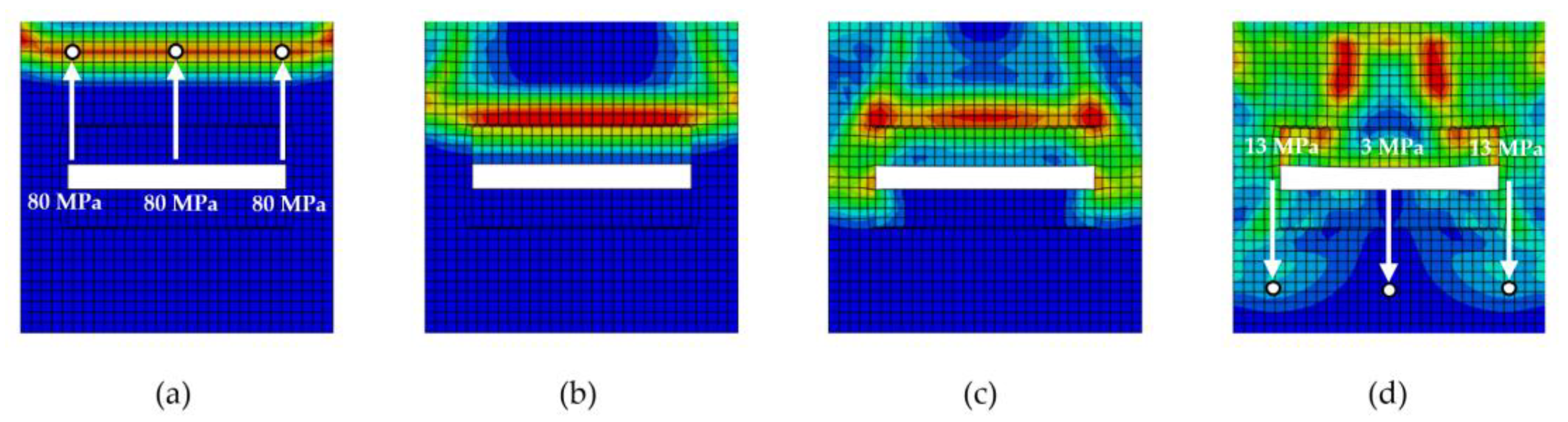
Figure 13.
Phase 4 for RUCinterlayer,(a) Em:Einterlayer = 1:0.2 (b) Em:Einterlayer = 1:0.5 (c) Em:Einterlayer = 1:1.5.
Figure 13.
Phase 4 for RUCinterlayer,(a) Em:Einterlayer = 1:0.2 (b) Em:Einterlayer = 1:0.5 (c) Em:Einterlayer = 1:1.5.
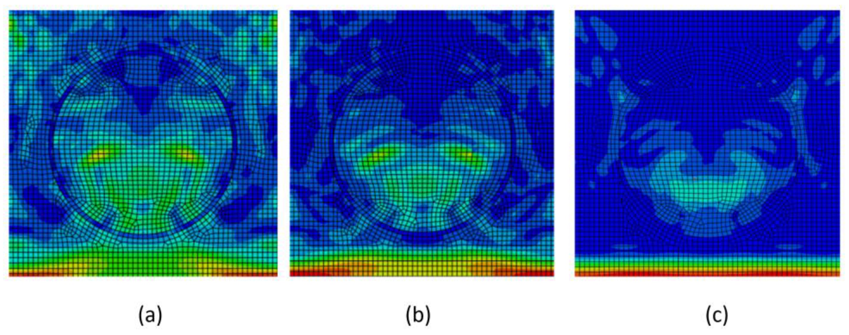
Figure 15.
Comparison of analyzed stress-wave attenuation values for different particle shapes rotated by 90°.
Figure 15.
Comparison of analyzed stress-wave attenuation values for different particle shapes rotated by 90°.
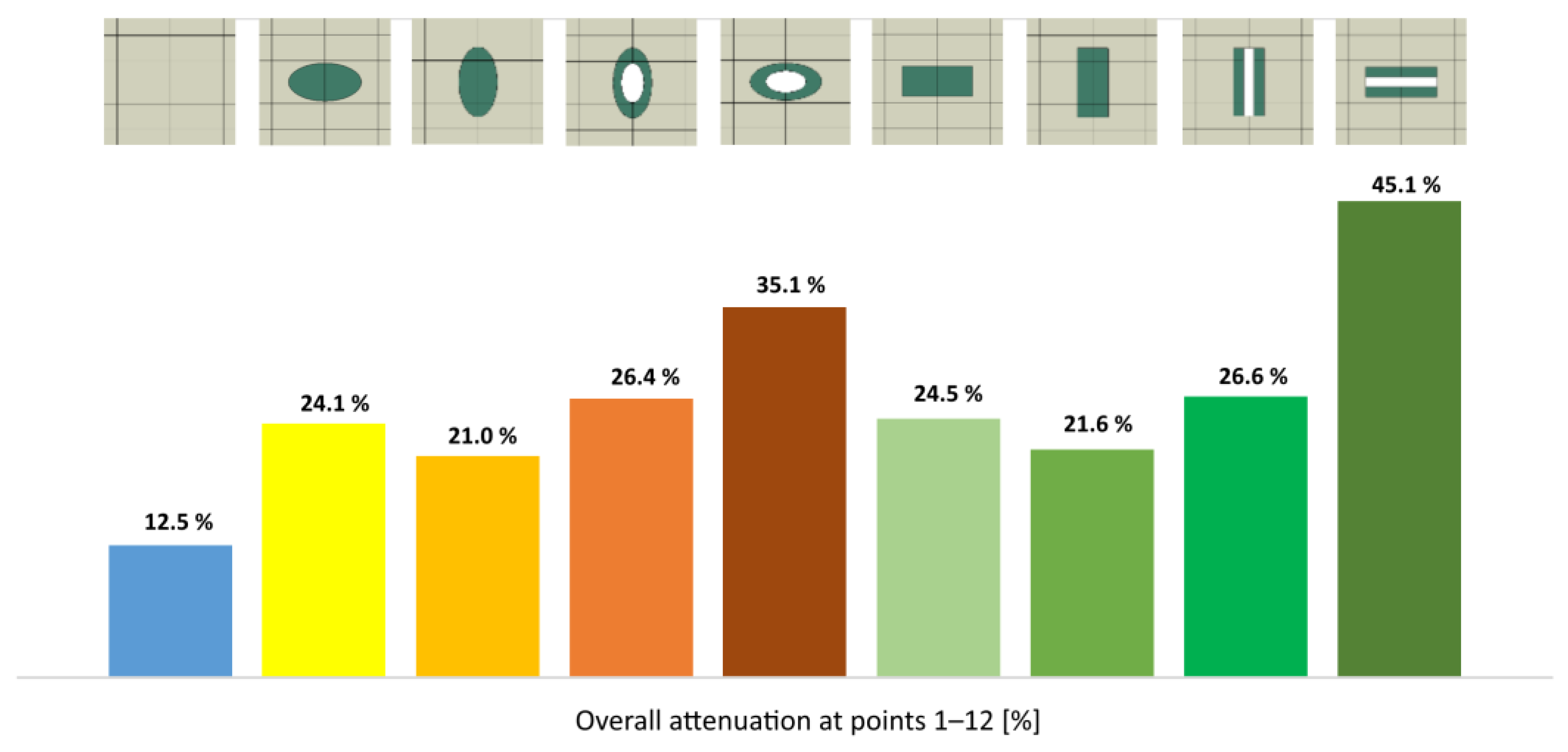
Figure 16.
Comparison of the interlayer effect on the level of damping.
Disclaimer/Publisher’s Note: The statements, opinions and data contained in all publications are solely those of the individual author(s) and contributor(s) and not of MDPI and/or the editor(s). MDPI and/or the editor(s) disclaim responsibility for any injury to people or property resulting from any ideas, methods, instructions or products referred to in the content. |
© 2025 by the authors. Licensee MDPI, Basel, Switzerland. This article is an open access article distributed under the terms and conditions of the Creative Commons Attribution (CC BY) license (http://creativecommons.org/licenses/by/4.0/).
Copyright: This open access article is published under a Creative Commons CC BY 4.0 license, which permit the free download, distribution, and reuse, provided that the author and preprint are cited in any reuse.


