
Submitted:
19 January 2026
Posted:
19 January 2026
You are already at the latest version
Abstract
Since approximately 2005, major processor manufacturers have shifted their architectural focus from instruction-level parallelism (ILP) toward multicore and manycore parallelism to achieve higher performance.Rather than relying on deeper pipelines and speculative execution, performance gains have increasingly been realized through thread-level parallelism (TLP).Consequently, the responsibility for efficiently utilizing processor resources has transitioned from hardware mechanisms to software implementations. This technical note examines design strategies for achieving deterministic, high-throughput packet processing on manycore architectures using the Data Plane Development Kit (DPDK).It presents a simplified Packet Gateway (PGW) pipeline implementation, analyzing cache-coherence effects, NUMA-local memory allocation, and multicore scheduling patterns critical to maintaining per-packet processing budgets under nanosecond-level constraints.
Keywords:
DPDK
; manycore
; cache coherence
1. Introduction
At modern data rates, the processing time available for a single packet is extremely limited. For instance, at 10 Gbps (14.88 Mpps), only 67.2 ns ( @ 3 GHz) are available to process each packet. Under such constraints, even a single CPU cache miss (32 ns) consumes nearly half of the per-packet processing budget. Two consecutive cache misses would exceed the allowable processing delay per packet (64 ns).
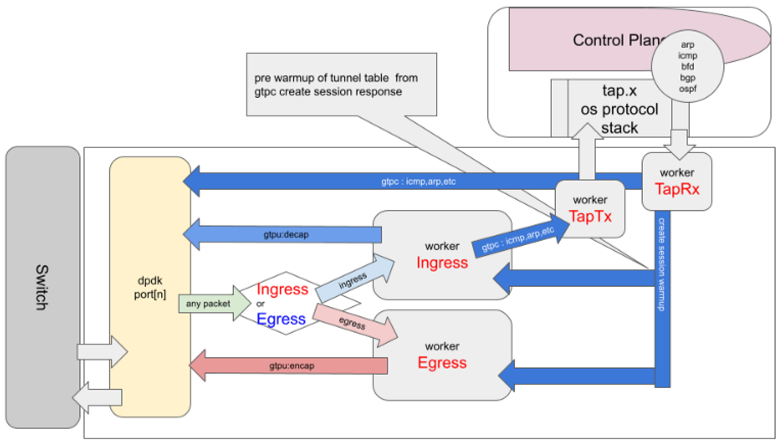
Figure 1.
PGW Overview.
In high-performance packet processing environments—such as those built using the Data Plane Development Kit (DPDK) [2]—the design must therefore minimize cache misses, system calls, and synchronization overheads.
On typical Intel Xeon architectures, socket buffers (s_buf) often reside in the L3 or L2 cache, and packet data can be placed directly into the cache through Data Direct I/O (DDIO) or Direct Cache Access (DCA) mechanisms.
Table 1 shows typical latency and synchronization costs observed on Intel Xeon systems [4]. In this paper, these values are used as a cost model that serves as the basis for design decisions. That is, they represent the constraints referenced during design, not actual measurements from mixi-PGW. For example, the difference between “L2 access 4.3 ns vs L3 access 7.9 ns” (approximately 3.6 ns) corresponds to about 5% overhead relative to the 67.2 ns per-packet processing budget, and the purpose of L2 boundary control is to prevent this difference from accumulating.
The programmer is provided with a synchronous access interface to the memory hierarchy, while the underlying hardware employs complex mechanisms and architectural designs to ensure that these accesses appear consistent and coherent across cores and threads. However, while such abstractions simplify programming, application designers still bear the responsibility to understand hardware-level coherence mechanisms—such as cache coherence protocols—and to design memory access patterns that align with them.
1.1. L2 Boundary
A group of CPU cores sharing the L2 cache is referred to as a boundary unit. In typical Intel Xeon architectures, SMT threads (hyper-threads) on the same physical core share the L2 cache. In mesh interconnect configurations, adjacent cores may also share L2. Data access within a boundary unit completes with L2 hit (approximately 4 ns, Table 1), while access crossing boundaries goes through L3 (approximately 8 ns) or NUMA crossing (tens of ns).
1.2. Limiting Data Crossing Boundaries
Data transferred across boundaries is limited to the following:
- Transferred: mbuf descriptors (pointers, 64 bytes or less)
- Not transferred: Packet payload body (processed by reference passing)
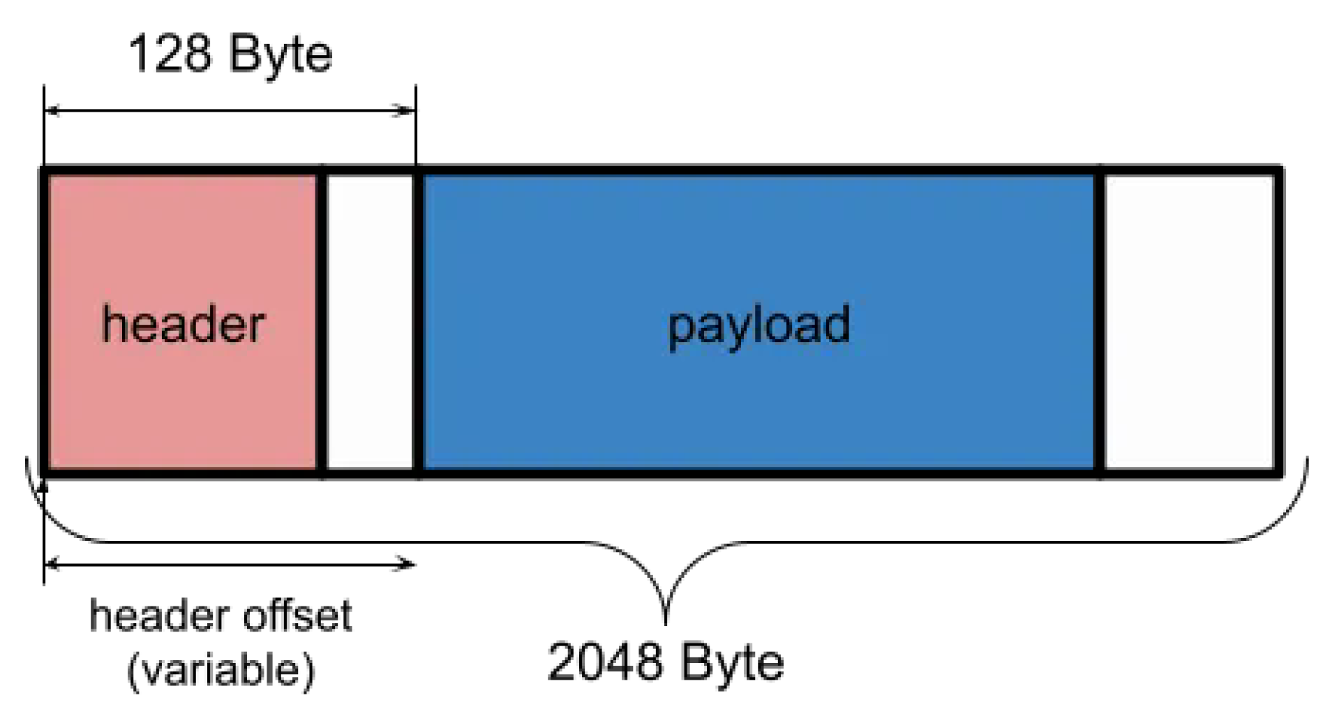
This minimizes cache line transfers across boundaries. The mbuf structure in Figure 7 is a design example that avoids payload copying through header offset manipulation.
- Core Placement: Pin RX/TX queues to cores within the same NUMA and L2 boundary (Figure 5)
- Pipeline Partitioning: Separate low-latency and high-latency processing into different core groups (Figure 6)
- Data Structures: Separate mbuf pools by NUMA node (Figure 4)
- Communication Patterns: Unify inter-core communication through burst transfers via SP/SC rings
The following sections of this paper explain the PGW pipeline design based on these definitions.
2. PGW
We implemented a Packet Gateway (PGW) system, 1 referred to as mixi-PGW, using the Data Plane Development Kit (DPDK) framework. The objective of this paper is to present and analyze several simplified pipeline scenarios of the PGW module built with DPDK, in order to illustrate key design considerations and performance characteristics of multicore packet-processing architectures.
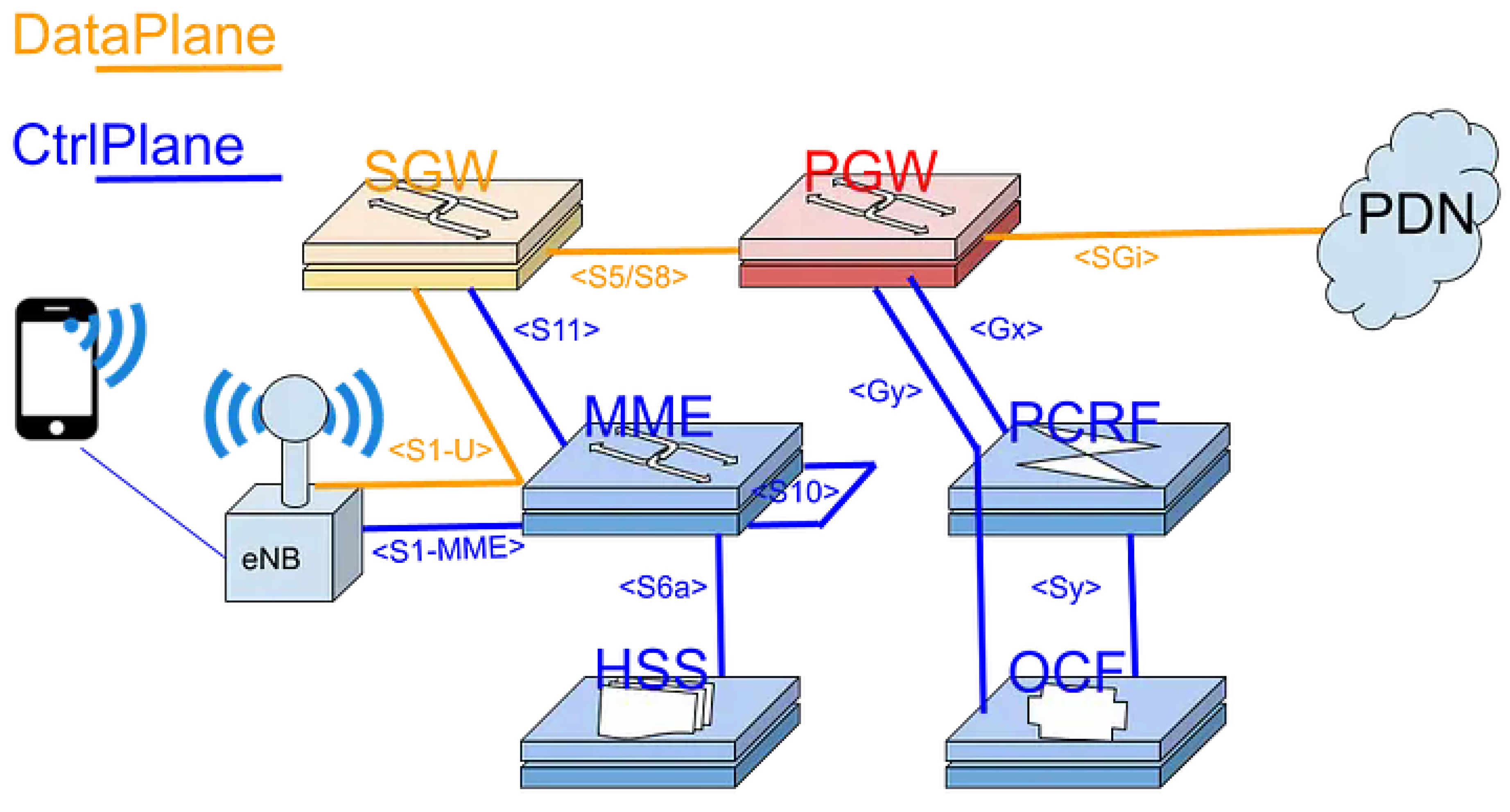
Figure 2.
pgw placed in mobile-network.
2.1. PipeLine Stage
To efficiently handle a large number of sessions within a single PGW data plane, it is essential to design a processing pipeline that achieves a well-balanced functional partitioning across CPU cores while maintaining low-latency operation Figure 3.
2.2. mbuf Pools
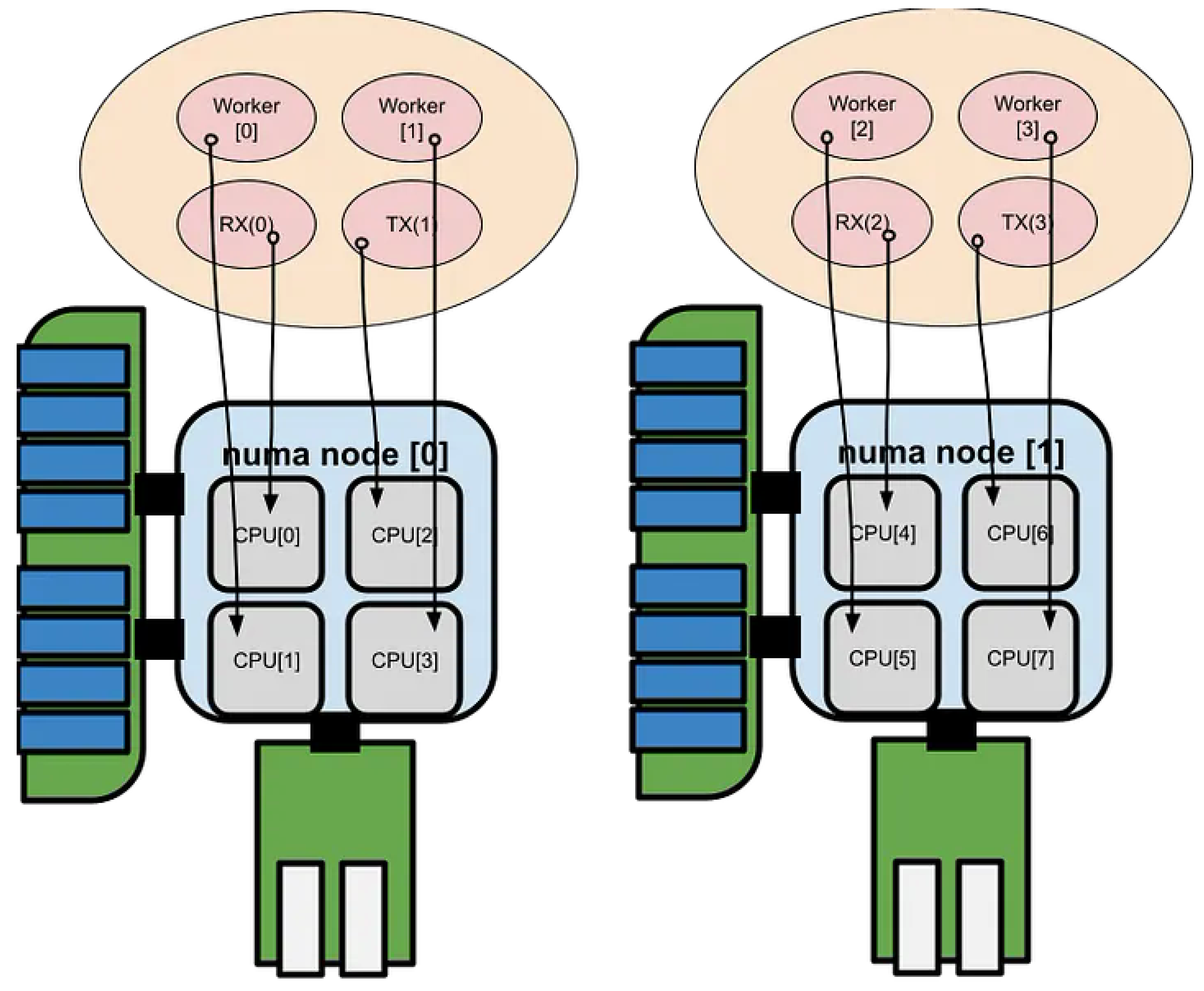
The receive (RX) functions cannot be invoked in parallel across multiple CPU cores, as packet reception for a given queue must remain serialized to preserve order and consistency. To achieve efficient utilization of the L3/L2 cache hierarchy, buffer pools are allocated on a per-NUMA-node and per-CPU-core basis, as illustrated below Figure 4.
2.3. Pool Mode Driver
Assign packet reception and Poll Mode Driver (PMD) processing to each NUMA node (or CPU-core group) to ensure locality of reference and minimize cross-node memory access latency.
Figure 5.
Pool Mode Driver.
2.4. Mixed Latency Path
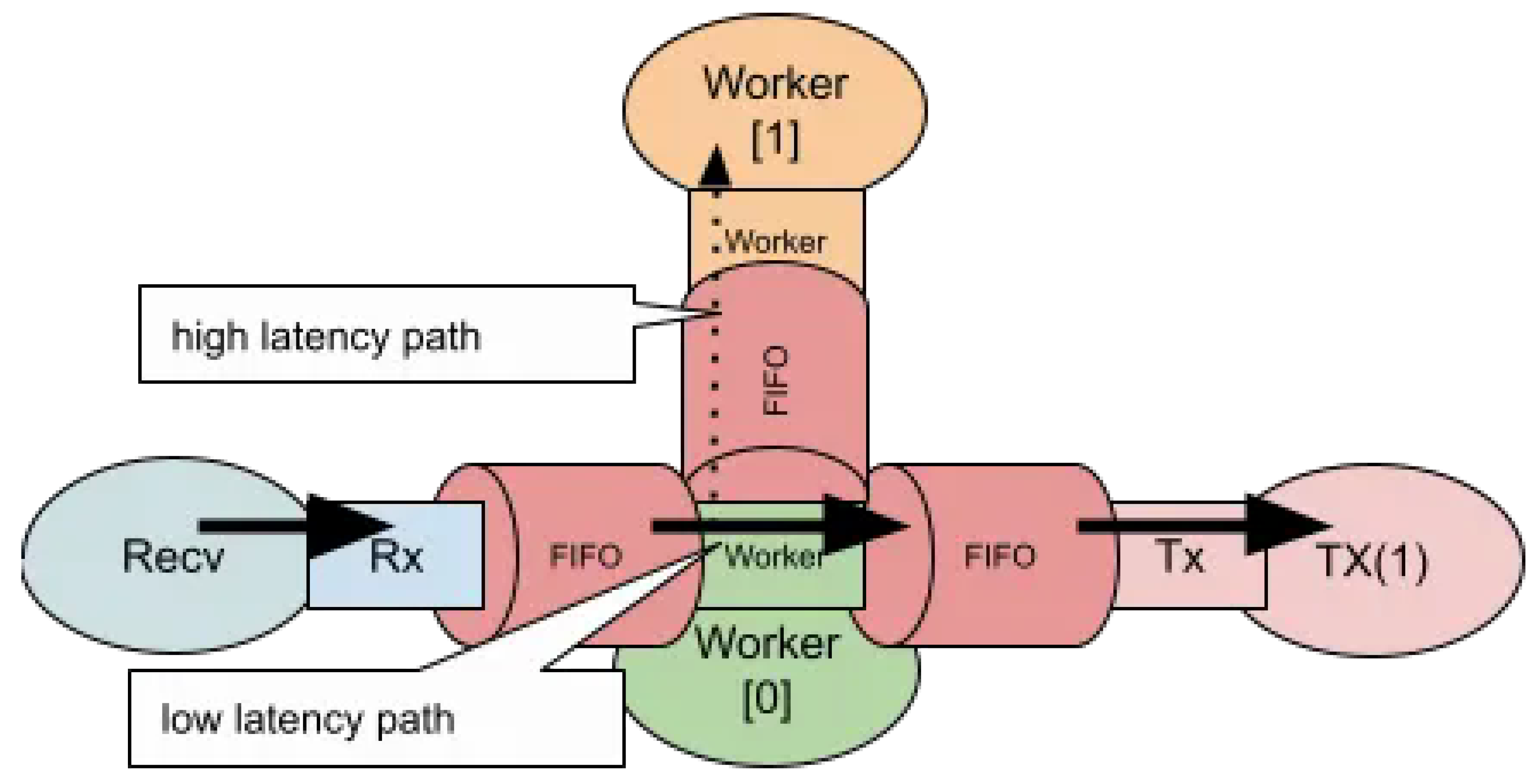
For scenarios that involve both low-latency and high-latency processing paths, a software ring is used to interconnect CPU cores, as illustrated below.
Figure 6.
Mixed Latency Path.
2.5. mbuf Structure
A variable header start position offset enables encapsulation and decapsulation processing to be implemented with minimal memory copy overhead.
Figure 7.
mbuf Strcture.
We applied ManyCore - pipeline design to PGW encap/decap processing as follows. Figure 1
The mixi-PGW source code is released under the MIT License. Users should be aware of and comply with the respective licenses of any linked dependency libraries. It is our hope that this article serves as a practical reference for implementing custom user logic with DPDK, and provides insight into the architectural design and optimization of high-performance packet processing systems.
2.6. PGW-Dataplane
Figure 8: Distributor Ingress/Egress Architecture — Each circled number represents a logical CPU core. The Distributor dynamically assigns ingress/egress workers to handle 0.5–1.0 million user sessions, maintaining NUMA locality and cache affinity through lockless rings between threads.
2.7. User Fairness
Figure 9 illustrates the User Fairness Control mechanism implemented in the PGW dataplane. Each user session is measured by a two-bucket policer consisting of a Committed Burst Size (CBS) and an Excess Burst Size (EBS). The policer follows the Single Rate Three Color Marker (SRTCM) algorithm defined in RFC 2697 [1], classifying packets into green, yellow, and red states based on whether they conform to or exceed the committed rate.
Packets marked as exceeding the Committed Information Rate (CIR) are re-marked by adjusting the DSCP field in the IP header according to the Differentiated Services framework defined in RFC 2474 and RFC 2475. This allows higher-layer schedulers or routers to enforce per-hop behaviors (PHBs) such as AF (RFC 2597) or EF (RFC 3246), ensuring fair bandwidth allocation across 0.5–1.0 million concurrent user sessions.
By implementing this fairness mechanism entirely in user space through DPDK, the system maintains deterministic per-session control without relying on kernel-level QoS subsystems, preserving NUMA locality and cache efficiency within the manycore architecture.
3. Packet Processing
Figure 10 and Figure 11 show the processing flow for GTP-U packet encapsulation and decapsulation, which are the main operations in the PGW data plane. In this design, CPU core is assigned to Ingress processing (decapsulation), CPU core is assigned to Egress processing (encapsulation), and each core independently references the session table (see Figure 8).
The critical path for packet processing in PGW is the session table lookup operation using the destination IP address (ip.dst) as the key. Specifically, the destination address is extracted from the inner IP header following the GTP-U header, and this is used as the search key to retrieve session information. Therefore, the number of sessions that can be accommodated in a single data plane is constrained by both (1) the capacity of the session table, and (2) the throughput of the lookup operation. In this design, these constraints were quantitatively evaluated to calculate the target session count per data plane.
Regarding the access pattern to the session table, a lock-free design was adopted that exploits the asymmetry between READ and WRITE operations. The data plane processing cores execute only READ operations on the session table, while WRITE operations from the control plane are processed asynchronously on a separate core. With this design, even in environments where L3 cache access across CPU cores occurs, we observed that lock-free data structures can improve throughput compared to exclusive control using DPDK standard rte_spinlock. As a result, this contributed to maximizing the number of sessions that can be accommodated in a single PGW.
4. Accelerated Network Application
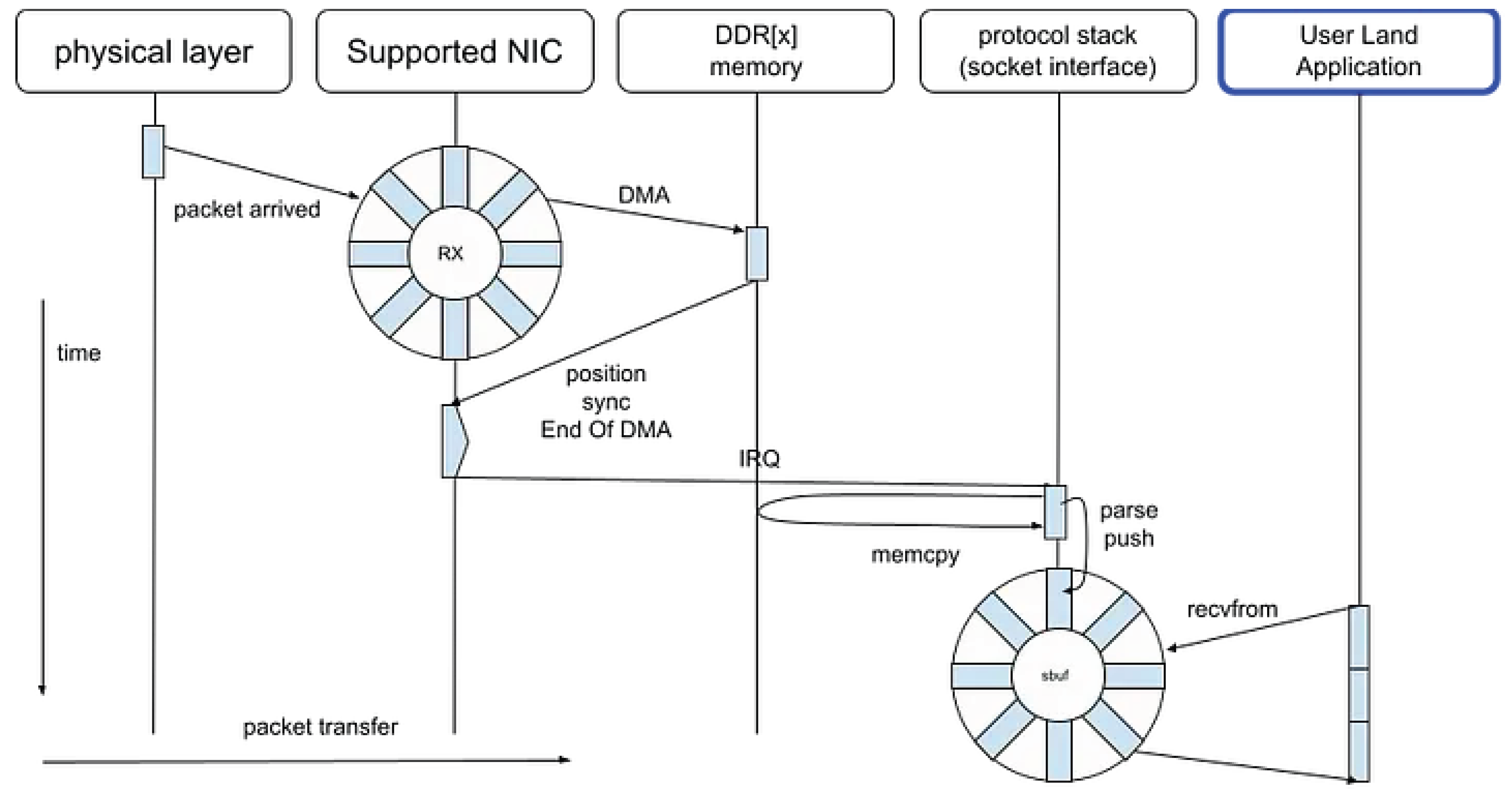
4.1. Legacy Socket
Typical BSD-Socket packet sequence in network application can be visualized as follows, with time on the Y axis and packet data on the X axis.
Figure 13.
Legacy Socket.
Even when abstracted through interfaces such as socket APIs, IOCP mechanisms, or various high-level frameworks, the underlying I/O mechanisms remain fundamentally identical. These abstractions differ primarily in their interface design, level of indirection, and implementation efficiency, but they ultimately rely on the same kernel-level primitives for asynchronous or event-driven communication.
For instance, the following libraries and functions represent conceptually equivalent approaches to I/O handling, despite variations in abstraction depth and runtime environment.
In essence, these systems are different manifestations of a common architectural principle: the delegation of I/O events to an event loop or completion mechanism that bridges user-space abstractions and kernel-level event notification.
4.2. DPDK PMD
As illustrated in Figure 14, traditional socket-based applications suffer from increased memory access latency due to cache coherency protocols operating across multiple cores. These coherency mechanisms, while essential for maintaining consistency, introduce additional synchronization and invalidation traffic within the shared memory hierarchy.
In contrast, the use of Poll Mode Drivers (PMDs) and Hugepages mitigates such overhead by improving both spatial and temporal locality of reference. PMDs eliminate interrupt-driven I/O overhead by continuously polling network interfaces, thereby reducing context-switching latency. Hugepages, on the other hand, enlarge memory page sizes to minimize Translation Lookaside Buffer (TLB) misses and enhance cache line utilization.
Figure 15.
DPDK(PMD) strategy.
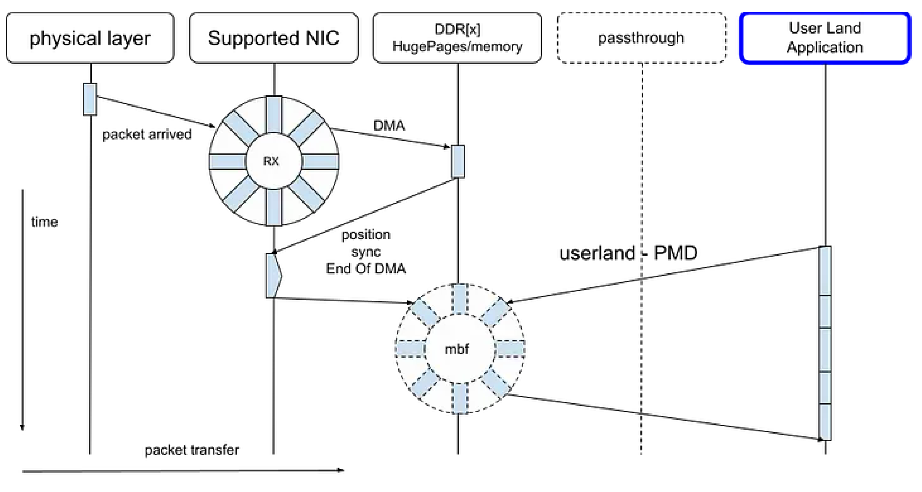
Consequently, the improved cache locality not only benefits the PMD-based packet processing pipeline but also reduces the adverse effects of coherency protocols, leading to higher throughput and lower latency in data plane operations.
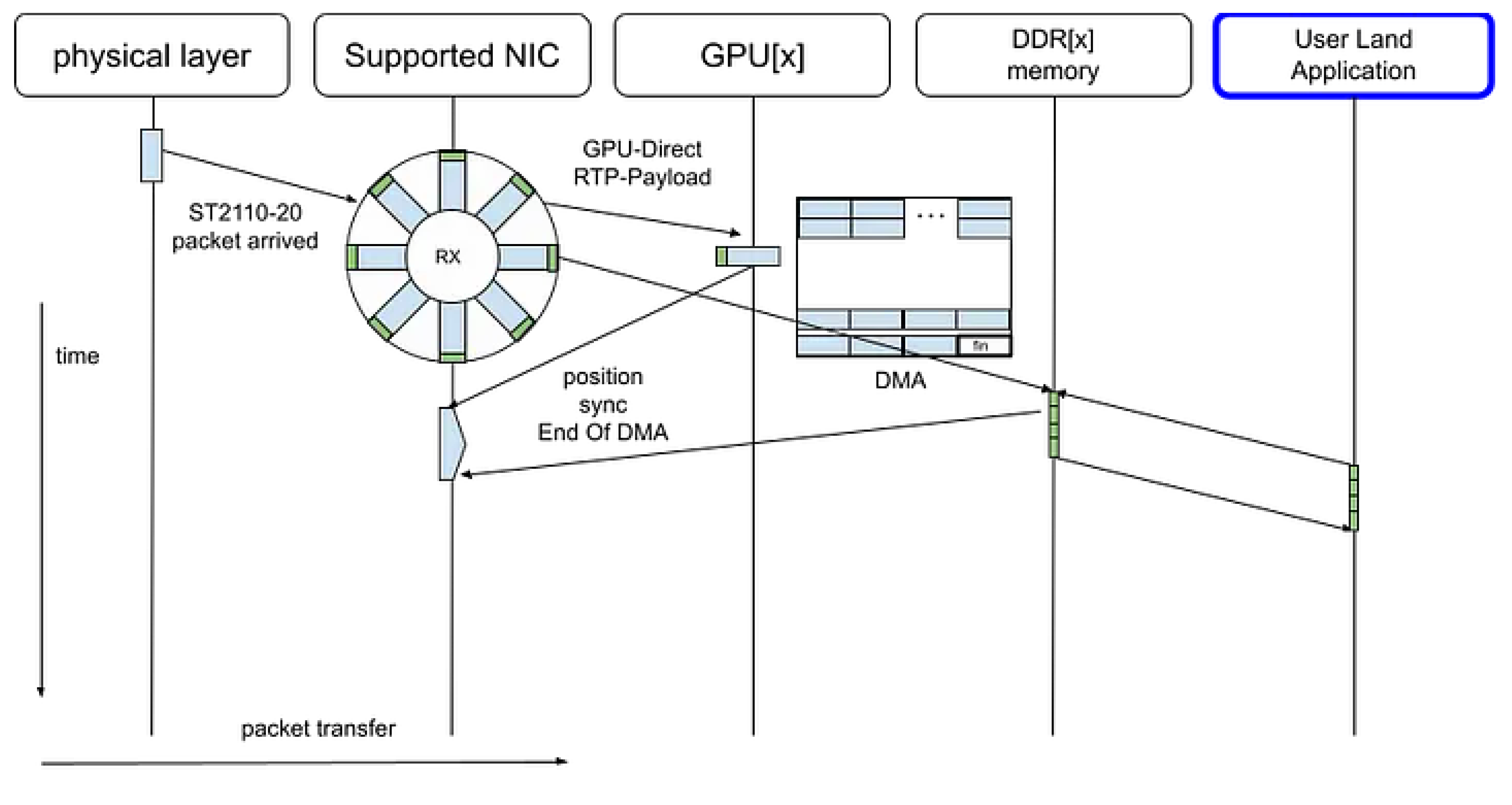
4.3. ConnectX GPU Direct
With the introduction of ConnectX GPU Direct and the Rivermax SDK, uncompressed ST 2110–20 video streams can be transferred directly from the network interface to the GPU via Direct Memory Access (DMA), completely bypassing the CPU memory subsystem [8].
In this configuration, the CPU is only responsible for lightweight control-plane operations, such as parsing the RTP headers to determine frame boundaries and initiating subsequent GPU-based processing tasks. These tasks include video composition, color space conversion, and format transformation.
Figure 16.
ConnectX GPU Direct.
By eliminating intermediate memcpy operations and avoiding CPU–GPU context switches, this approach minimizes latency and maximizes throughput, enabling real-time video pipeline execution with deterministic performance characteristics.
It should be noted that this method was employed solely for the purpose of data-path comparison with the DPDK PMD, and is not appropriate for application to general-purpose packet processing such as the packet gateway presented in this paper. ConnectX GPU Direct is particularly well-suited for applications characterized by high-bandwidth and regular data flows, such as uncompressed video streams conforming to ST 2110–20.
5. Related Work
5.1. Netmap
Netmap [3] is a high-performance packet IO framework that extends the traditional kernel network stack by providing a shared memory interface between user space and the NIC driver. It enables applications to exchange packets through preallocated ring buffers with minimal system call overhead. However, its operation fundamentally depends on kernel-level support: the host system must include a netmap-enabled network driver. This dependency limits its portability and restricts fine-grained control over the IO path, particularly in environments where the kernel is not easily modified or where kernel-bypass is preferred.
In our early prototype, we initially employed a PMD (Poll Mode Driver) design built upon netmap, leveraging its low-latency buffer exchange to achieve zero-copy packet transfer. While this approach simplified kernel interaction, it constrained the implementation when scaling beyond a few cores, as the netmap kernel module imposed synchronization and buffer management overheads not easily optimized from user space.
In contrast, our current design adopts DPDK’s fully user-space PMD architecture, which detaches the IO datapath from the kernel entirely. DPDK allows explicit mapping of RXTX queues to dedicated logical cores, NUMA-local memory pools, and lockless rings between worker threads. This model enables deterministic control over cache locality, prefetch timing, and flow-to-core affinity. These capabilities are essential for sustaining wire-speed throughput in a ManyCore environment where the processing budget per packet is limited to a few hundred CPU cycles.
Therefore, while netmap provides a pragmatic kernel-extended path suitable for prototyping or controlled environments, our DPDK-based design was selected to realize a fully kernel-independent data plane optimized for ManyCore scalability, NUMA locality, and fine-grained scheduling.
5.2. fd.io/VPP (Vector Packet Processing)
The PGW pipeline presented in this study adopts a design in which memory copies across the L2 cache boundary are explicitly controlled by an application-level FIFO. This enables deterministic management of inter-thread data movement and cache locality. In contrast, VPP employs a highly abstracted graph-node model [5], where the data paths and cache behaviors between nodes are encapsulated within the framework. As a result, it provides limited visibility and control over low-level optimizations.
Therefore, while FD.io/VPP offers a versatile and high-throughput packet-processing infrastructure, its abstraction layer makes it less compatible with multi-core pipeline designs—such as the PGW presented here—that rely on explicit data transfers and cache-level optimization at the L2 granularity.
5.3. NetVM
NetVM [6] proposed a high-performance and flexible framework that bridges user-space packet processing with virtualization by leveraging huge-page sharing between the hypervisor and guest VMs. It enables true zero-copy packet transfer and in-hypervisor switching, allowing flows to be dynamically steered between network functions with minimal overhead. Specifically, NetVM achieves this through
- DMA from the NIC into shared huge pages
- lightweight descriptor rings between the hypervisor and each VM
- shared page references across trusted VMs
This design yields throughput improvements of up to 2.5× over SR-IOV, sustaining near line-rate performance for 64B packets on 10 GbE links (see Figure 10 Forwarding rate as a function of input rate for NetVM,... in the original NetVM paper). The framework also introduces NUMA-aware thread assignment and adaptive VM load balancing.
While NetVM focuses primarily on service chaining across virtual machines, this work targets a fundamentally different design point: intra-application manycore and NUMA optimization for DPDK-based data-plane processing. Using a PGW (GTP-U encapsulation/decapsulation) pipeline as a case study, our design explicitly quantifies per-packet processing budgets (67.2 ns at 10 Gbps, 14.88 Mpps) and decomposes latency into cache, memory, and synchronization costs (Table 3). We then propose strategies that avoid virtualization-induced overheads entirely—such as NUMA-local mbuf pool allocation, fixed RX/TX queue–core mapping, explicit L2 boundary control, and hybrid low- and high-latency worker pipelines (Figure 4, Figure 5, Figure 6 and Figure 7).
Key Differences
- System boundaries: NetVM optimizes inter-VM communication through shared huge pages and hypervisor switching. Our work instead optimizes a single-process, multi-threaded data path, eliminating context-switch and IOTLB overheads entirely.
- NUMA granularity: Although NetVM considers NUMA locality, our design formalizes it at the mbuf pool and core level, detailing explicit placement and synchronization strategies for deterministic latency.
- Pipeline composition: NetVM supports flexible VM service chaining; our pipeline focuses on mixed-latency flow handling, offset-variable header processing, and copy-minimized encapsulation paths.
- Target domain: NetVM is suitable for NFV and multi-tenant environments, while our system addresses deterministic, carrier-grade data-plane workloads (e.g., PGW) where predictable per-packet latency is paramount.
Why This Work Still Matters Since NetVM, user-space I/O frameworks such as DPDK have become widespread. However, in environments operating at 100 GbE or with multi-level tunneling, the dominant bottlenecks have shifted: from inter-VM data transfer to cache hierarchy latency, NUMA cross-access, and synchronization contention within a single process. Our work complements NetVM by providing quantitative insights (ns-level cost models) and implementation patterns for such modern data-plane bottlenecks, offering a platform-agnostic foundation for deterministic performance on manycore systems.
5.4. Barrelfish Operating System
Barrelfish [7], developed by ETH Zürich and Microsoft Research, proposed a multikernel operating system architecture designed to scale across manycore processors. Its fundamental principle was to eliminate shared kernel state and instead let each CPU core run an independent kernel instance, communicating explicitly via message passing. This design sought to treat the hardware as a distributed system, rather than as a uniformly shared-memory machine, thereby improving scalability and predictability as core counts increased.
Our proposed PGW system can be regarded as a user-space realization and evolution of this concept. Specifically, the PGW architecture expresses the Barrelfish multikernel philosophy at the application level, forming a distributed multi-user-kernel architecture within the cloud environment. Each processing element (DPDK worker, NUMA-local pipeline, or virtual node) functions as an autonomous execution domain, coordinating through explicit, protocol-defined communication rather than shared kernel state. In this sense, our implementation demonstrates that the multikernel design principles of Barrelfish can be achieved and verified in user space, without requiring OS-level modification.
Furthermore, whereas Barrelfish validated its model within experimental kernel infrastructure, our PGW system adopts the same distributed coordination and cache-local design philosophy to practical packet data planes running atop existing Linux environments. Thus, it provides empirical evidence that Barrelfish’s scalability-oriented architecture can be extended beyond kernel research into operational, cloud-native network functions.
5.5. DPDK: eventdev, rte_graph
In recent DPDK (Data Plane Development Kit), the graph execution model rte_graph was introduced around 2020-05 (DPDK 20.05) 2, and since 2023, acceleration through vectorization such as rte_node_enqueue_x4 has progressed 3. In 2025-07 (25.07), feature arcs 4 and in 2024-11 (24.11), management APIs such as node xstats were established 5, systematizing the graph model as a framework.
Chronological Relationship between mixi-PGW and rte_graph: At the time we designed and implemented mixi-PGW in 2017, rte_graph was in the conceptual stage and was not implemented as a standard DPDK interface. Therefore, in mixi-PGW, we had to design and implement independently the graph-based pipeline execution functionality that is now provided by rte_graph, rte_node_enqueue_x4, etc.
Specifically, the distributor (Figure 8), inter-core communication via SP/SC lockless rings (Listing 2), and L2 boundary-aware core placement design presented in this paper are prior implementations that solved design challenges equivalent to those of the rte_graph framework, which later became a DPDK standard, as of 2017.
With the systematization of rte_graph as a DPDK standard since 2020, the option to adopt rte_graph for new development has emerged. However, the principles of L2 boundary control defined in this paper (boundary definition, limiting crossing data, control methods) remain valid as lower-layer design knowledge that should be referenced for node placement and mbuf pool design even when using rte_graph. Furthermore, similar cache locality design is required in the latest hardware environments such as GPU-Direct and Accelerated NICs.
6. Conclusions
6.1. Contributions
This paper reported design principles for manycore packet processing using the Data Plane Development Kit (DPDK), based on the implementation experience of a Packet Gateway (PGW). The contributions of this paper are the following three points:
- Formalization of L2 Boundary Control: We defined a design pattern consisting of three elements: “L2 boundary,” “limiting crossing data,” and “control methods,” and presented it as a reusable guideline applicable to other DPDK applications.
- Explicit Design Rationale Based on Cost Model: We explicitly presented the constraints such as L2/L3 access costs and lock costs against the processing budget of 67.2 ns per packet (at 10 Gbps), and quantitatively demonstrated the rationale for design decisions.
- Recording of Prior Implementation Before rte_graph: We recorded the experience of independently designing and implementing functionality provided by the rte_graph framework, which became a DPDK standard in 2020, as of 2017.
6.2. Significance of Re-Presenting 2017 Results
The implementation presented in this paper is based on mixi-PGW 6, which was designed and implemented by the authors in fiscal year 2017 and later released under the MIT License. Although the original MVNO project was subsequently discontinued, the significance of re-presenting it in this paper lies in the following points:
- From the current perspective where rte_graph has been standardized, the positioning as a prior implementation was clarified
- It was demonstrated that similar cache locality design is required even in the latest technologies such as GPU-Direct and Accelerated NICs
6.3. Limitations and Future Work
In this paper, we presented a performance comparison between locked and lock-free approaches for the main processing of PGW, session table lookup (Figure 12). However, the operational environment at that time no longer exists, and reproduction of end-to-end measurements under actual traffic is difficult. As future work, re-verification of the principles of L2 boundary control in the latest DPDK (rte_graph) environment is mentioned.
Please refer to the mixi-PGW source code for implementation examples of the design principles described in this paper. The source code is released under the MIT License on GitHub.
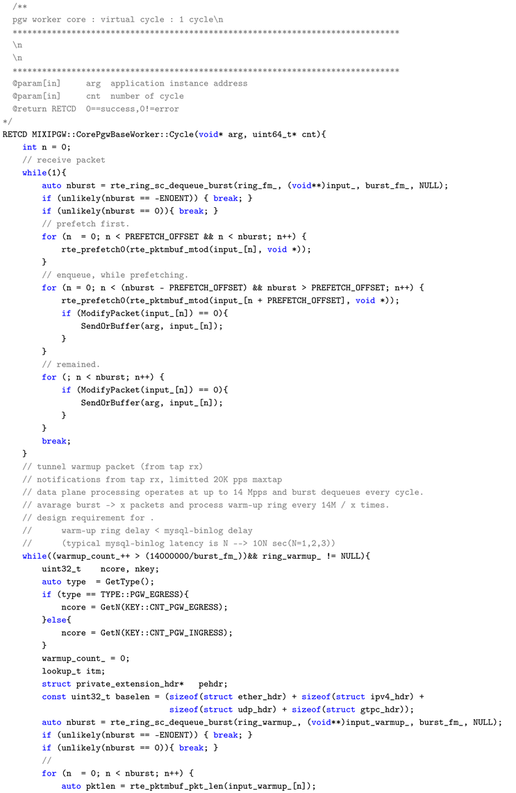
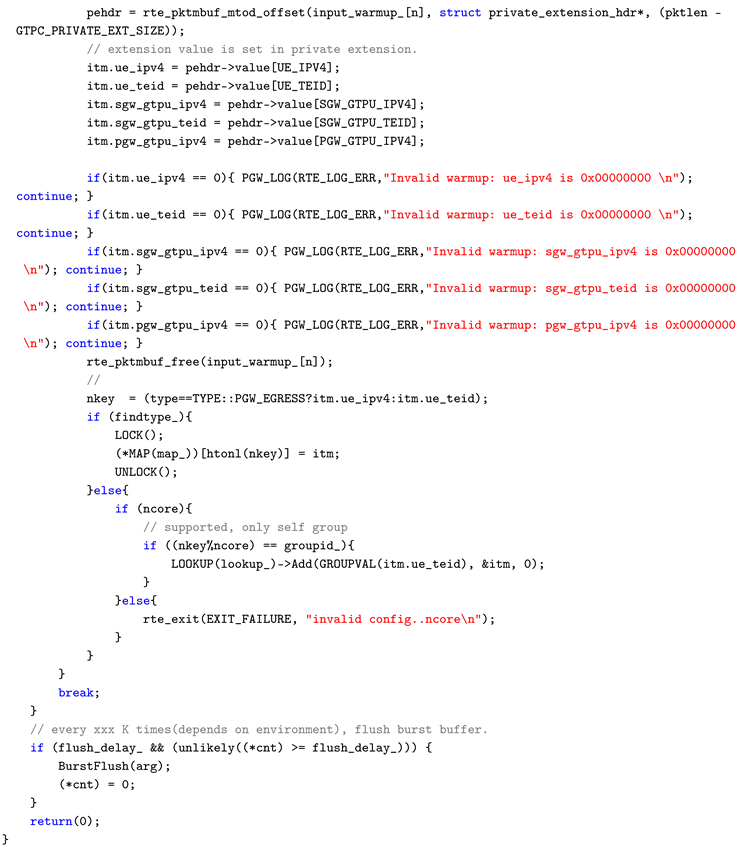
Appendix A. Main Cycle Processing (Cycle Function)
dataplane/src/core/core_pgw_base_worker.cc
Appendix A.1. Overview
The CorePgwBaseWorker::Cycle() function constitutes the main loop of the PGW worker core. It executes a single cycle from packet retrieval to transfer to the next phase, under an environment assuming short-packet line-rate traffic at 10 Gbps / 14.88 Mpps.
Appendix A.2. L2 Boundary Control Implementation Points
- SC (Single Consumer) Dequeue: Packets are burst-retrieved in a lockless manner using rte_ring_sc_dequeue_burst(). By using SC mode, contention between multiple consumers is eliminated, guaranteeing processing within the L2 boundary.
- Cache Optimization through Prefetching: Using rte_prefetch0(), the mbuf PREFETCH_OFFSET packets ahead of the processing target is preloaded into the L2 cache. This allows L2 hits to be expected during actual processing, avoiding latency increase due to cache misses.
- Burst Processing: Rather than processing packets one by one, dequeue, processing, and enqueue are performed in burst units. This reduces loop overhead and enables effective utilization of cache lines.
This function is a concrete example showing how the three elements of L2 boundary control (boundary unit, limiting crossing data, control methods) defined in this paper are realized in actual code. In particular, the combination of prefetching and burst processing has reference value as a practical technique for absorbing the L2/L3 access cost difference shown in Table 3.7
| Listing 1: core_pgw_base_worker.cc |
|
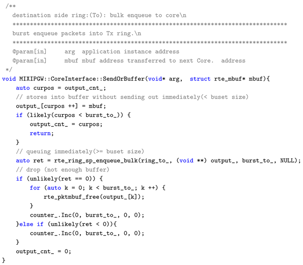
Appendix B. Burst Transfer Processing (SendOrBuffer Function)
dataplane/src/core/cores.cc
Appendix B.1. Overview
The CoreInterface::SendOrBuffer() function transfers processed packets to the next-stage core. Rather than sending immediately, it buffers until the burst size is reached, then enqueues in bulk.
Appendix B.2. L2 Boundary Control Implementation Points
- SP (Single Producer) Enqueue: Bulk transfer is performed in a lockless manner using rte_ring_sp_enqueue_bulk(). SP mode eliminates contention on the producer side.
- Bursting through Buffering: Rather than enqueueing immediately each time a packet arrives, packets are accumulated in a local buffer until reaching burst_to_ count. This reduces the frequency of ring access and improves cache line efficiency.
- Explicit Release on Drop: When the ring is full, rte_pktmbuf_free() immediately releases references to unused areas in HugePages. In high-speed processing systems without GC, immediate release of resource ownership contributes to overall system resource optimization.
This function is the concrete implementation of “burst transfer” in Table A1. It has reference value as a design pattern for reducing transfer frequency while maintaining throughput in inter-core communication crossing L2 boundaries.

Table A1.
Components and Implementation of L2 Boundary Control.
| Control Method | Effect | Implementation |
|---|---|---|
| NUMA-local mbuf pool | Avoid NUMA crossing | Figure 4 |
| SP/SC lockless ring | Avoid lock contention | rte_ring_sc_dequeue |
| Burst transfer | Cache line efficiency | Listing 2 |
| Listing 2: cores.cc |
 |
References
- J. Heinanen and R. Guerin, "A Single Rate Three Color Marker (SRTCM)," RFC 2697, IETF Network Working Group, September 1999. Available at: https://datatracker.ietf.org/doc/html/rfc2697.
- Intel Corporation. DPDK: Data Plane Development Kit Programmers Guide. Intel Corporation, latest edition. https://www.dpdk.org/.
- Rizzo, L., Netmap: A Novel Framework for Fast Packet I/O. In USENIX Annual Technical Conference (USENIX ATC 2012), 2012. https://www.usenix.org/conference/atc12/technical-sessions/presentation/rizzo.
- Jesper Dangaard Brouer, “Network Stack Challenges at Increasing Speeds: The 100 Gbit/s Challenge,” LinuxCon North America, August 2015. Available at: http://events17.linuxfoundation.org/sites/events/files/slides/net_stack_challenges_100G_1.pdf.
- Cisco Systems, “FD.io / VPP (Vector Packet Processing),” 2016. Available: https://fd.io/.
- J. Hwang, K. K. Ramakrishnan, and T. Wood, “NetVM: High Performance and Flexible Networking Using Virtualization on Commodity Platforms,” in Proc. USENIX NSDI, 2014. https://www.usenix.org/system/files/conference/nsdi14/nsdi14-paper-hwang.pdf.
- “Barrelfish: Exploring a Multicore OS,” Microsoft Research Blog, July 7, 2011.URL: https://www.microsoft.com/en-us/research/blog/barrelfish-exploring-multicore-os/.
- NVIDIA Corporation, NVIDIA Rivermax SDK Documentation, Available: https://developer.nvidia.com/networking/rivermax.
| 1 | |
| 2 | |
| 3 | |
| 4 | |
| 5 | |
| 6 | |
| 7 |
Figure 3.
Overview of balanced pipeline stage.
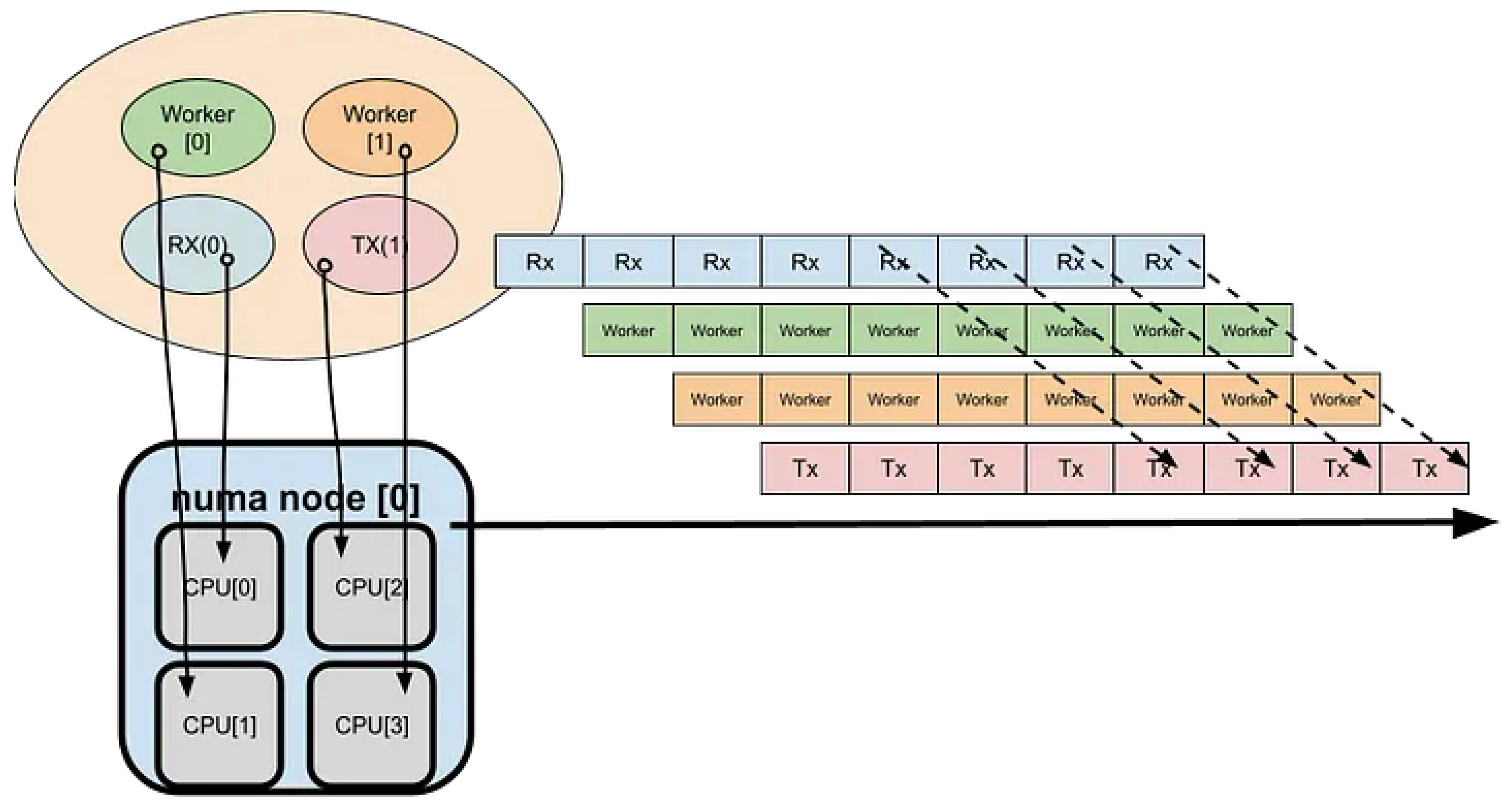
Figure 4.
mbuf pools.
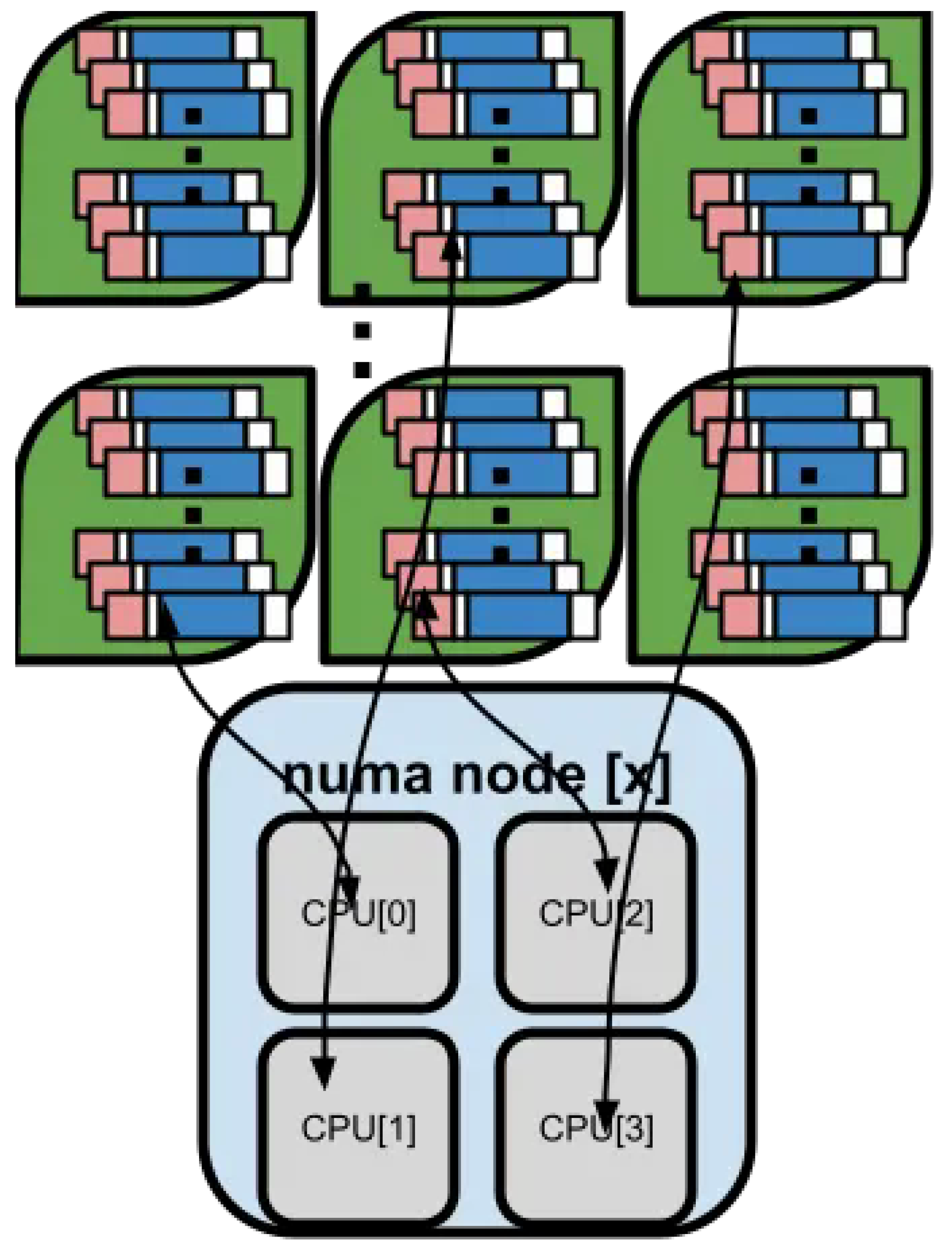
Figure 8.
Distributor Ingress/Egress.
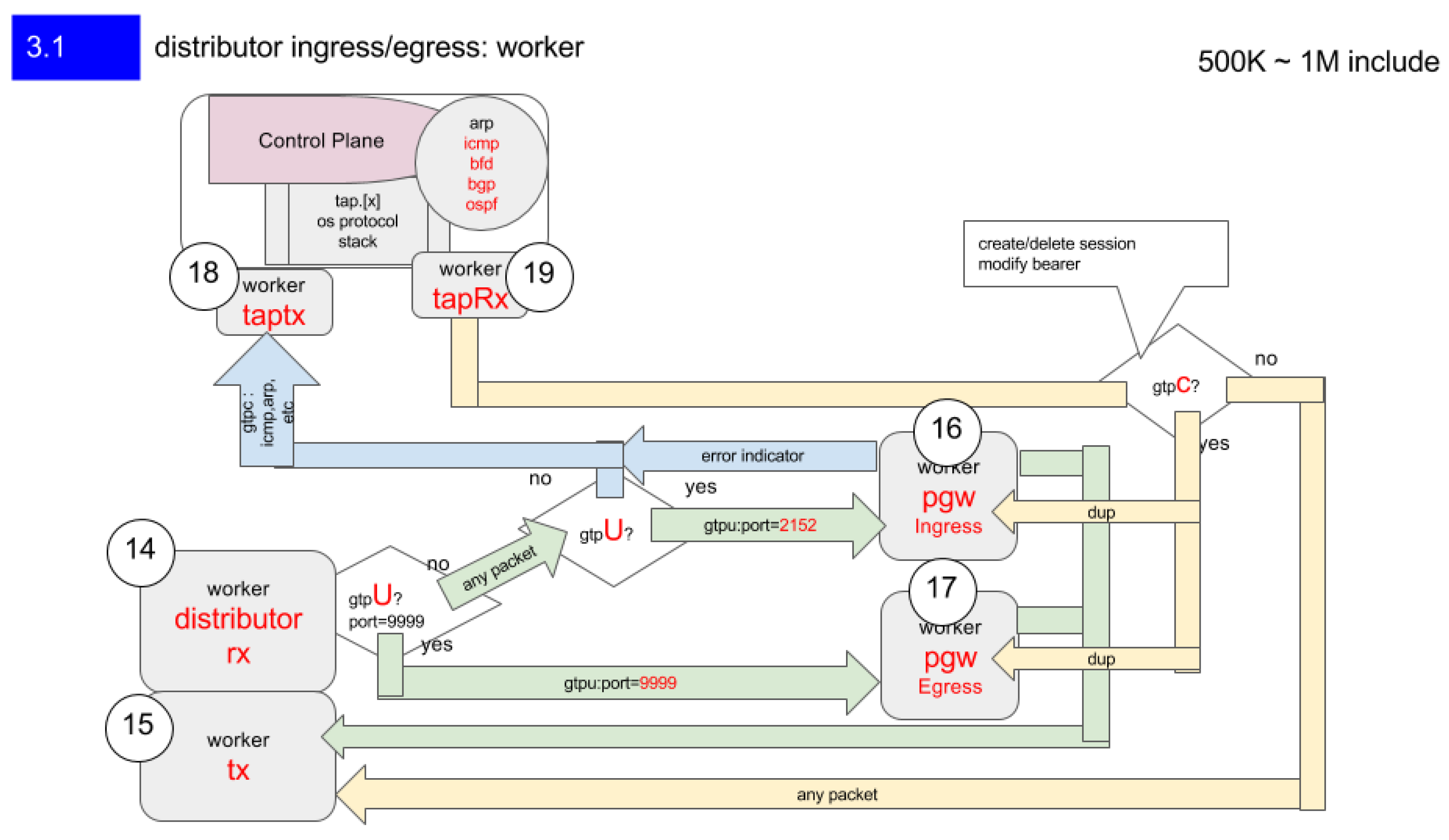
Figure 9.
User Fairness Control.
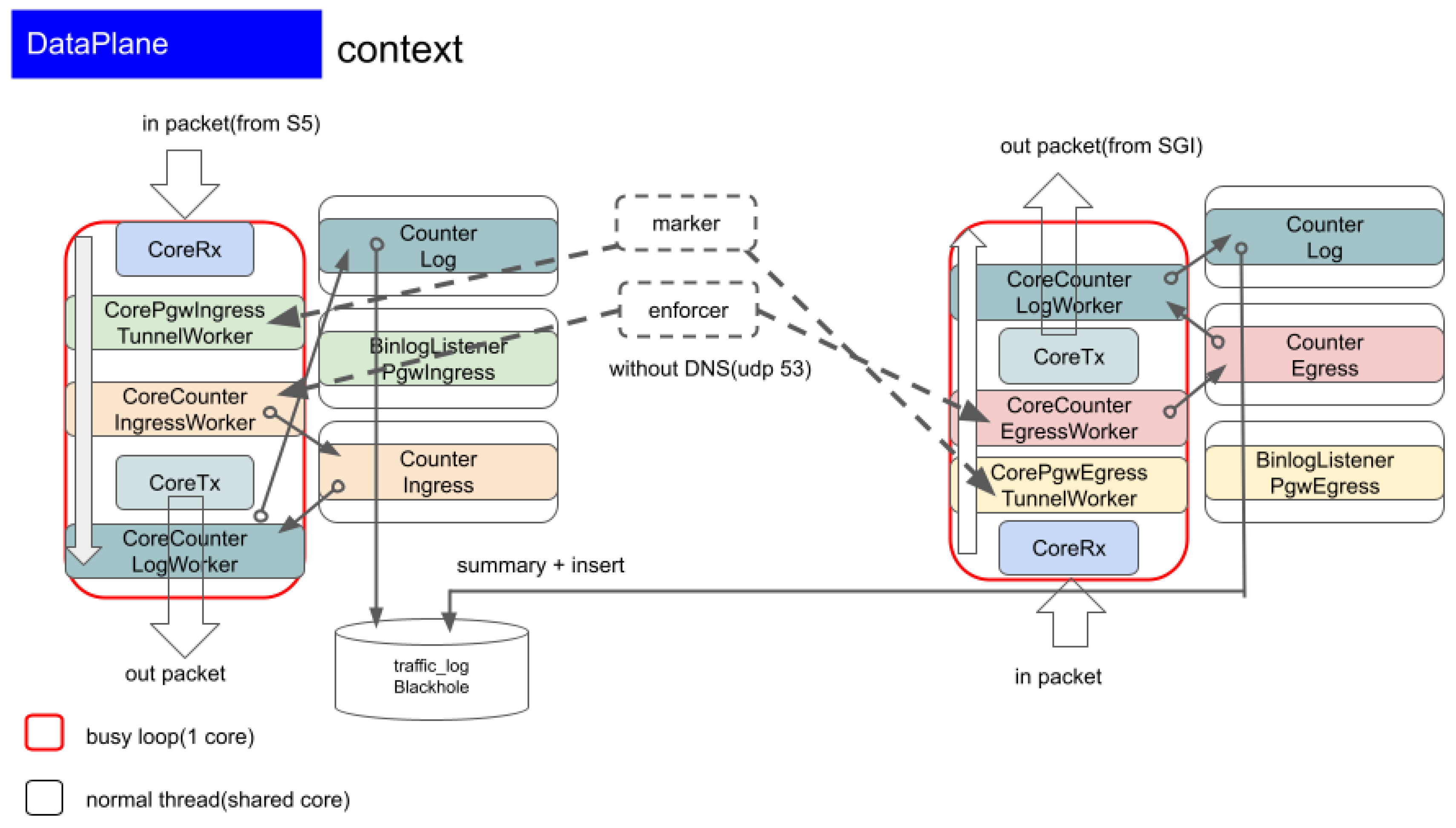
Figure 10.
Ingress Processing.
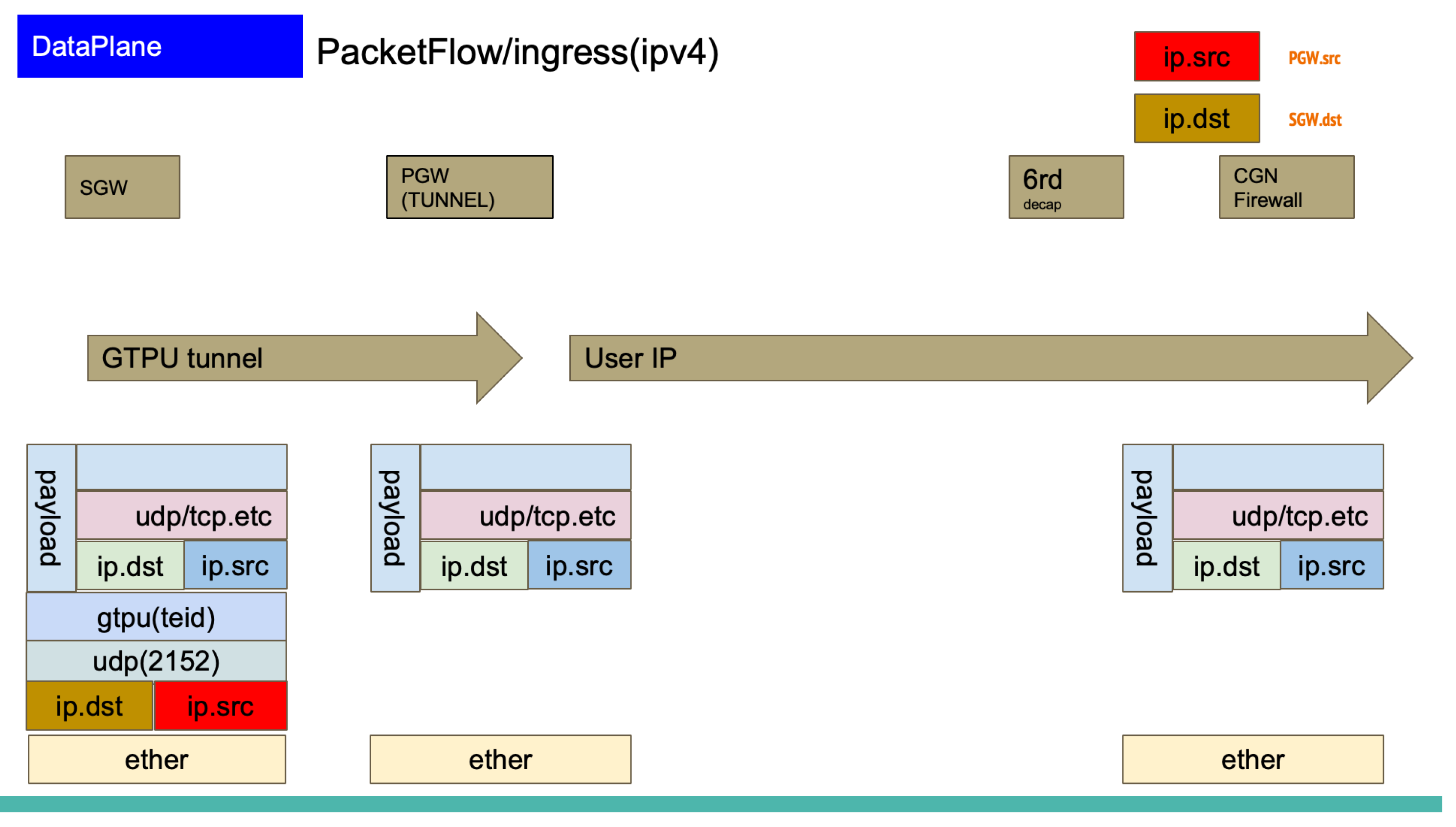
Figure 11.
Egress Processing.
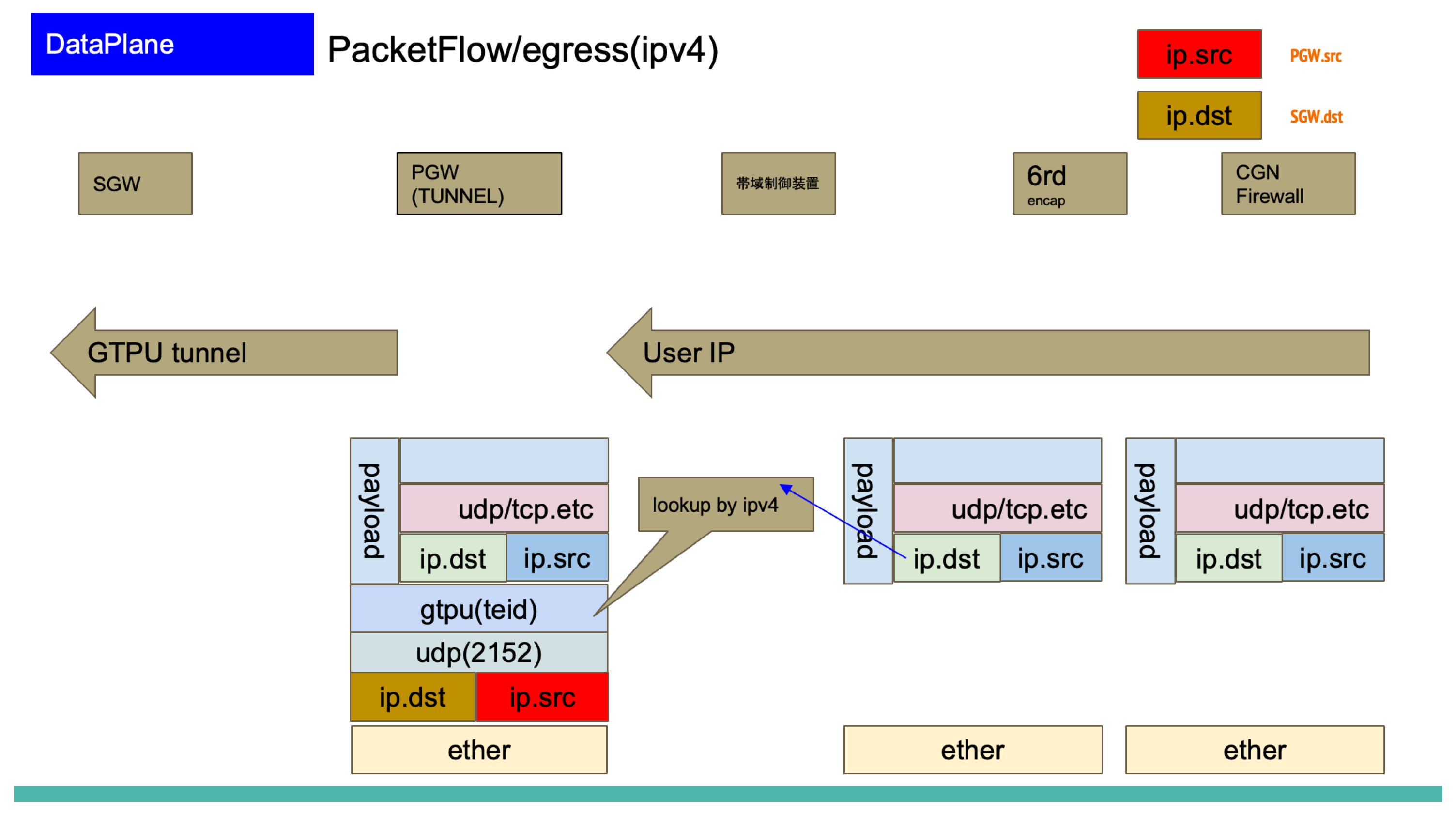
Figure 12.
PGW Main Packet Processing Cost.
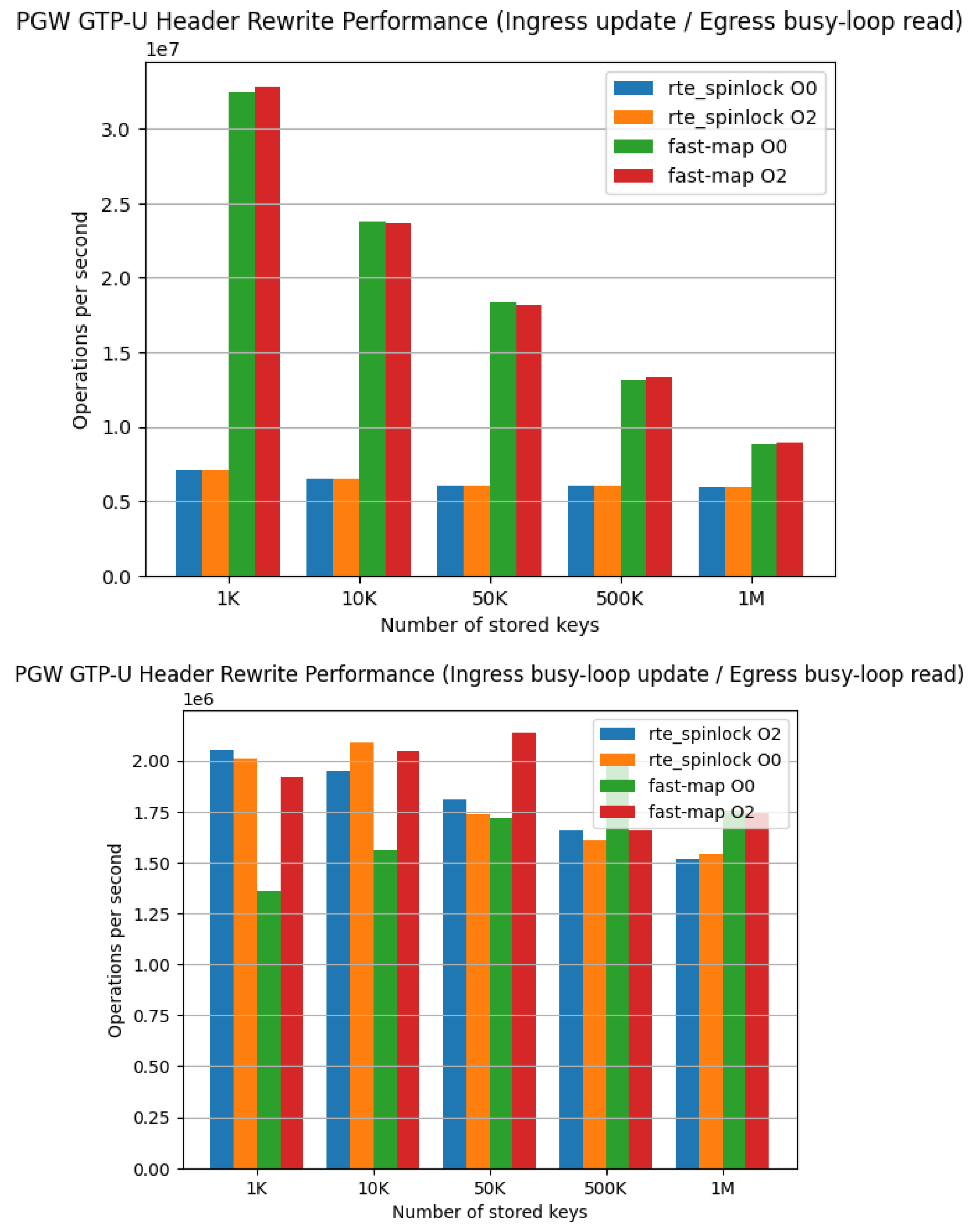
Figure 14.
Coherency Architecture.
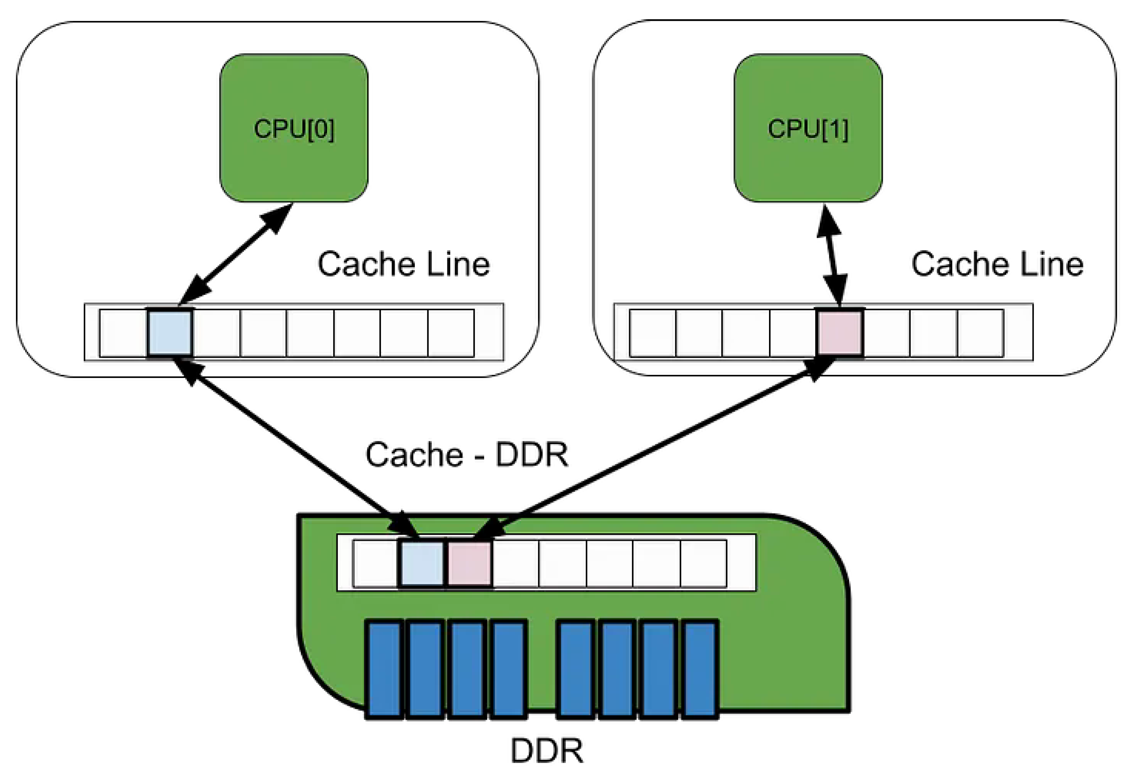
Table 1.
Internal Performance [4].
Table 1.
Internal Performance [4].
| Key | Value | Note |
|---|---|---|
| 67.2 ns | 201 cycles @3GHz |
at 10Gbps / 14.8Mpps, time available for processing a single packet |
| CPU cache miss | 32 ns | CPU cache miss time |
| CPU cache miss x 2 | 64 ns | Running out of available delay per packet |
| socket buffer: s_buf | fast | Hits L3/L2 cache in most cases |
| placed to L3 cache directly | packet cache |
at Intel E5-xx, Data Direct I/O (DDIO) or DCA |
| L2 access cost | 4.3 ns | lat_mem_rd 1024 128 |
| L3 access cost | 7.9 ns | lat_mem_rd 1024 128 |
| atomic lock | 8.2 ns | 17–19 cycles |
| optimized spin lock | 16.1 ns | 34–39 cycles |
| system call overhead | too big | a few system call invocations consume over 67.2 ns |
| synchronized cost | ||
| spin_ [lock/unlock] | 34 cycles 13.943 ns |
simple |
| local_BH_ [disable/enable] | 18 cycles 7.410 ns |
SW interrupt |
| local_IRQ_ [disable/enable] | 7 cycles 2.860 ns |
HW interrupt |
| local_IRQ_ [save/restore] | 37 cycles 14.837 ns |
HW interrupt + status |
Table 2.
Performance Measurement Environment.
| Item | Configuration |
|---|---|
| CPU | Intel Xeon E5 (Sandy Bridge-EP) |
| Sockets | 2 |
| NUMA Configuration | 2 nodes (memory controller × 2) |
| L3 Cache | Shared on die |
| Memory Latency | L1: 4 cycles |
| L2: 26–31 cycles | |
| Local Memory: 190 cycles | |
| Remote Memory: 310 cycles |
Table 3.
Representative abstractions of I/O mechanisms across different environments.
| Name | Description |
|---|---|
| libevent | Event-driven I/O abstraction based on callback-oriented socket operations. |
| socket(2) + select(2) | Legacy synchronous socket API using select(2) for multiplexing. |
| fread(3) | Buffered binary stream I/O abstraction layered on top of system calls. |
| FUdpSocket Receiver |
UDP socket wrapper within Unreal Engine 4’s networking subsystem. |
| IOCP | Windows-specific asynchronous I/O mechanism based on I/O Completion Ports. |
| Any runtime socket wrapper | Language-level abstractions of socket primitives (e.g., Python, Go, Rust). |
| Netty | High-performance asynchronous network framework for the Java runtime. |
Disclaimer/Publisher’s Note: The statements, opinions and data contained in all publications are solely those of the individual author(s) and contributor(s) and not of MDPI and/or the editor(s). MDPI and/or the editor(s) disclaim responsibility for any injury to people or property resulting from any ideas, methods, instructions or products referred to in the content. |
© 2026 by the author. Licensee MDPI, Basel, Switzerland. This article is an open access article distributed under the terms and conditions of the Creative Commons Attribution (CC BY) license (http://creativecommons.org/licenses/by/4.0/).
Copyright: This open access article is published under a Creative Commons CC BY 4.0 license, which permit the free download, distribution, and reuse, provided that the author and preprint are cited in any reuse.


