Submitted:
20 October 2025
Posted:
21 October 2025
You are already at the latest version
Abstract
This paper portrays an experimental study to understand the compressive performance of FRP-confined concrete-filled steel tube (FCCFST). Columns CFST columns have large strength and good deformability characteristics which make it precious structural members. The large lateral stiffness and strength, as well as the large load-carrying capacity that is obtained by a steel tube and concrete interaction, are sufficiently procured in the CFST columns. Concrete-filled steel tube columns are promoted for superior performance due to the composite action between the concrete core and the steel tube. However, the full potential of this composite action is often not realized because of the differing dilation properties between the materials, which could lead to debonding at the interface. To address this issue, external confinement using FRP is proposed to enhance the bonding between the concrete and steel tube. In this study, seventy-two columns were verified to examine the effects of various factors, including the number of carbon fiber reinforced polymer (CFRP) layers, steel tube thickness, and infilled concrete properties (with and without silica slurry and polypropylene fiber) on the columns' load capacity and axial deformation capacity. The experimental load-carrying capacity of the columns was also compared with those obtained from existing formulations proposed by some researchers. It is observed that the external CFRP wrap helps constrain the steel tube's outward local buckling deformation and enhances the concrete core's confinement. The results also demonstrate that CFRP confinement significantly improves the load capacity and axial distortion capacity of the CFST columns. The prediction performance of existing formulations was varied, however, one of the proposed ones estimates the experimental values with reasonable accuracy.
Keywords:
carbon fiber reinforced polymer
; concrete-filled steel tube columns
; confinement
; strengthening
; ultimate loads
1. Introduction
Concrete-filled steel tube (CFST) columns emerged as a viable structural element in civil engineering owing to their superior strength, flexibility, and fire resistance. These columns consist of a steel tube encasing concrete. The steel imparts significant tensile strength to the concrete, maintaining its position, while the concrete core sustains compressive loads and prevents local buckling of the steel tube. This synergy improves structural efficiency, especially in compression members, making CFST columns increasingly used in high-rise buildings, bridges, and various infrastructure projects.
Contemporary structural systems frequently utilize CFST columns. The concrete core prevents the steel tube from buckling inward; outward inelastic local buckling may compromise the steel's confinement, strength, and flexibility [1,2,3] offered supplementary transverse confinement external to the steel tube to mitigate its outward buckling. This alteration, referred to as a confined concrete-filled steel tube column, has garnered interest, especially in using fiber composite materials. These materials are recognized for their superior strength-to-weight ratio, corrosion resistance, and flexibility, rendering them optimal for improving the performance of CFST columns. They conducted experiments to observe the effects of variations in unconfined compressive strength [4,5], corner radius, aspect ratio, and the quantity of fiber-reinforced polymer (FRP) utilized to bond the concrete prisms. Their findings indicated that plastic strain diminished with increased unconfined concrete strength. [6] conducted experiments on twenty-six circular double-skin steel tubular short columns filled with polymer concrete and subjected to axial compression. Investigating concerns of local instability and fortification enhancement. The research indicated that the columns demonstrated ultimate axial strengths 10-30% greater than the aggregate strengths of the individual components. The confinement effect enhanced both strength and ductility.
The volumetric strain can be reduced by encasing specimens in FRP. This prevents the specimens from expanding during axial compression tests.[7] developed a formula that precisely predicted the stress-strain behavior of FRP-confined concrete cylinders for samples from the same research region. This study employed several materials and configurations to verify the load capacity of circular FRP-confined CFST columns. Nevertheless, it failed to consider these columns' dynamic or seismic responses. Structural design and safety evaluations must comprehend the nonlinear behavior of FRP-confined CFST columns. This differs from steel confinement, which sustains steady pressure post-yielding. The FRP material enhances confining pressure as the concrete core expands under load [8]. The uniaxial compressive strength and strain of FRP-confined concrete are markedly superior to those of unconfined concrete. The stress-strain curve for FRP-wrapped concrete generally exhibits a bi-linear pattern, with the ultimate compressive strength and the associated strain improved with adequate application of FRP. Insufficient FRP may lead to a declining post-peak curve [7].
Additional investigations on FRP-confined CFST columns have been undertaken to assess correlations, including axial load and axial shortening. These connections encompass axial load-axial strain and axial load-hoop strain. Research has investigated the influence of these characteristics on ultimate load and axial shortening capacity. The study additionally examines the efficacy of FRP wraps and the characteristics of restricted concrete. The steel casing of CFST columns functions as both longitudinal and transverse reinforcement. Applying restricting pressure on the concrete to avert inward buckling. This reinforcement enhances the stability and strength of the column as a system. The ultimate strength of CFST columns is affected by material characteristics, including concrete compressive strength and steel yield strength. Furthermore, geometric characteristics, including the cross-sectional shape, significantly influence the width-to-thickness ratio. Furthermore, consider the spacing and diameter of the reinforcing ties.[9,10] Noted that optimal confinement is achieved when the fibers are oriented in the direction of hoop stresses. This approach enhances two critical aspects of CFST performance: the wrap's confinement significantly strengthens the concrete core, and it prevents the steel tube from bowing outward. This method prolongs the linear segment of the load-deformation curve. Their findings demonstrated substantial enhancements in ultimate compressive strength and failure strain.[11] examined the behavior of fiber-composite-restricted concrete-filled steel tube columns with circular and square cross-sections under compression. It was observed that in circular columns, the load capacity was augmented with an increase in the number of carbon fiber-reinforced polymer layers despite a reduction in ductility. To address this issue in the study, we utilized silica fume (SF) and polypropylene fibers (PP) to enhance the ductility of concrete.
Concrete with silica fume is recognized for its superior strength and durability [12]. The specific surface area of silica fume (SF) affects the workability of concrete. Research demonstrates that augmenting silica fume (SF) diminishes the slump of concrete, with a reduction from 85 mm to 65 mm noted as SF content escalates from 0% to 6% [13]. The particle size distribution of SF substantially influences workability [14,15,16] investigated the tensile strength of steel-fiber-reinforced concrete and determined that the incorporation of fibers markedly improved the concrete's tensile strength. The utilization of SF diminishes permeability, water absorption, voids, long-term cracking, freeze-thaw cycles, and temperature fluctuations while enhancing durability, strength, stiffness, flexibility, and tensile strength. The incorporation of SF and high-performance fibrillated polypropylene fibers into concrete may alter its viscosity, eccentricity, dilation angle, and (k) factor, all of which are indicators of the concrete's flexibility. Polypropylene fibers enhance the toughness and ductility of concrete, enabling greater deformation before fracture. Generally, the incorporation of steel fibers and polypropylene fibers enhances the mechanical qualities of concrete, including its compressive strength and ductility. [17] investigated the influence of SF concentration on concrete absorption at 28 and 180 days. A marginal decrease in absorption was observed with the rise in SF content. They also discovered that SF significantly influenced the porosity of concrete [18]. In conclusion, employing SF with reduced particle sizes may minimize concrete absorption and improve durability. The carbon fiber-reinforced polymer jacketing, the thickness of the steel tubes, and the strength of the concrete are related to the ultimate load and ductility of the CFST short columns. It also contrasts the ductility of steel tube columns filled with plain concrete against those filled with concrete with silica fumes and polypropylene fibers. The experimental and analytical results on the load-bearing capacity of the composite columns were assessed. The study's findings were presented and discussed in a comparative manner. This paper presents an experimental study aimed at gaining a further understanding of the compressive behavior of FRP-confined concrete-filled steel tube columns.
2. Methodology
2.1. Test Specimens
Seventy-two specimens were subjected to axial loading tests. The assembly comprised eighteen CFST columns and fifty-four CFRP-CFST columns constructed from carbon fiber-reinforced polymer-confined concrete-filled steel tubes. In the investigation, the number of FRP layers (nf) was established at 0, 1, 2, and 3; the thickness of the steel tubes was determined to be 1.8, 2.8, and 3.8 mm; and the nominal compressive strength of the concrete was designated as 20, 30, and 40 MPa. Every specimen exhibited a length-to-diameter ratio (L/D) of 2. The characteristics of the columns are detailed in Table 1, Table 2 and Table 3. The designation of the specimen is provided in the first column of the tables. The abbreviation "CF" denotes CFST specimens, which are succeeded by several FRP layers. The letter "t" and the subsequent numeral indicate the steel tube and its thickness in millimeters. The designations "C" and "CF" represent infilled concrete with and without silica slurry and polypropylene fibers, respectively, while the subsequent number indicates the nominal concrete strength in MPa. CF0t1.8C20 denotes CFST columns constructed from 1.8 mm steel tubes and concrete with a nominal strength of 20 MPa. CF1t1.8CFS20 denotes CFST columns composed of silica fume and polypropylene fiber in concrete with a nominal strength of 20 MPa.
2.2. Material Properties
The columns were cast using three different concrete mixtures as given in Table 1. The nominal concrete compressive strength was shown in Table 1 as 20, 30, and 40 MPa. The columns were constructed using six concrete combinations, both with and without polypropylene fiber and silica slurry. The specified nominal concrete compressive strengths were 20, 30, and 40 MPa. For each mixture, three concrete cylinder specimens were evaluated to ascertain the actual compressive strength of the concrete. The average compressive strength (fc) of the concrete for different column specimens is displayed in Table 2, Table 3 and Table 4. This study utilized well-graded crushed coarse aggregates. The highest particle size was 25 mm, and the fineness modulus was 4.93. The fine aggregate utilized in this investigation was river sand, with a maximum particle size of 4.75 mm and a fineness modulus of 3.46. The cement utilized is Ordinary Portland Cement (OPC CEM/I 42.5R). A specific type of polypropylene fiber was utilized. The material possesses a specific gravity of 0.9, a tensile strength ranging from 137 to 689 MPa, and a Young's modulus between 3.4 and 4.8 GPa. The dark gray silica fume slurry utilized had a density of 1.30 gm/m³ and a solid concentration of 50%.
Seamless steel tubes were used in this study as the steel formwork for all the columns. Different diameter-to-thickness ratios were obtained using steel tubes of 1.8, 2.8, and 3.8 mm in thickness. The original 3.8 mm seamless steel tube was machined to create the 1.8 mm and 2.8 mm tubes. Coupon testing was used to evaluate the steel tube's properties. The steel tube's yield strength (fy) and elastic modulus (Es) were found to be 307 MPa and 230 GPa, respectively. The columns were reinforced with carbon fiber. To ascertain the tensile characteristics of carbon fiber,[19] performed tensile tests on flat coupons. Elastic modulus (Ef) was 230 GPa, the ultimate strain (εfu) was 2.1%, the tensile strength (ft) was 4900 MPa, and nominal thickness (tf) was 0.34 mm. The epoxy resin used in this investigation came from a solvent-free, two-component composition. Components A (resin) and B (hardener) have a 4:1 weight ratio. According to the manufacturer, the epoxy resins elastic modulus, tensile strength, and shear strength were 15 GPa, 35 MPa, and 13 MPa, respectively.
2.3. Preparation of Specimens
To get the desired length, the round steel tubes were carefully chopped and machined. To get rid of any remaining oil and grease, the tubes' interior surfaces were wire-brushed. Each steel tube had a robust end cap attached to the base that was 10 mm thick. A poker vibrator was used to consolidate the layers of concrete that had been placed. Before the CFRP wrapping was applied, the samples were left in the lab for 28 days to cure. Fibers were orientated in the direction of the hoop when the FRP wrap was placed using the wet lay-up process. After first cleaning the steel tube's surface with alcohol, a single continuous fiber sheet was applied and wrapped around the tube to produce the required number of piles. The fiber sheet's terminal end was 150 mm longer than its initial end. To provide uniform bond thickness and remove air bubbles, a paddler roller was used. Before testing, a wire brush was used to abrade the top surface of the concrete core. The prepared surface was then covered with a thin layer of high-strength cement. The goal of this strategy was to lessen the effects of concrete shrinkage. allowing the concrete core and steel tube to be loaded simultaneously during testing.
2.4. Test Setup and Instrumentation
The tests were conducted using a global testing apparatus with a 4000 kN capability. The test setup for the specimens is shown in Figure 1. Until the maximum load was reached, the load progressively increased at 50-kN intervals, with each interval lasting two to three minutes. To investigate the post-peak behavior of the columns, the load was applied gradually up to and beyond the maximum load. A dial gauge was used to measure displacement and axial shortening. To guarantee uniformity of compression, preliminary tests were carried out within the elastic range. Dial gauges on the testing apparatus were used to carefully calibrate the specimen's position to obtain measurements.
3. Results and Discussion
3.1. General Studies
In addition to the localized outward buckling of the steel tube at its ends, the CFST specimen showed continuous expansion in the mid-height region. CFST specimens are shown in Figure 2. As seen in Figure 3a, the specimen showed notable axial shortenings. All the FRP-CFST specimens failed because the lateral expansion of the concrete caused the FRP wrap to burst in the mid-height area. Figure 3b shows the distinct failure modes of the FRP-CFST specimens. Compared to the CFST specimens, the FRP-CFST specimens showed reduced localized buckling of the steel tube and volumetric expansion of the concrete.
The results indicated that steel tube columns filled with a blend of polypropylene fiber and silica slurry outperformed those filled with standard concrete. These steel tube columns demonstrated performance comparable to those with increased steel tube thickness. Achieving ductile behavior requires a tube with either high strength or a low diameter-to-thickness ratio, hence escalating building costs. Enhancing the performance of the concrete core offers a cost-effective method for improving the behavior of concrete-filled steel tube columns. The use of fibers in conventional concrete has proven effective in diminishing its inherent brittleness.
Integrating fibers into concrete columns improves their performance more cost-effectively than addressing local buckling in the steel tubes of CFST columns. This outcome is logical as the concrete core substantially enhances the load-bearing capacity of CFST columns, particularly those with slender tubes. The experiments revealed the advantageous impacts of improved tensile and flexural strengths, together with increased stiffness, relative to conventional concrete. Columns in high-rise structures with a low story height typically have a diminished length-to-diameter ratio, and those made with high-strength concrete are more liable to brittle shear failure under axial load [20]. Experiments were performed to assess the influence of fiber-reinforced polymer (FRP) on short steel tube columns filled with concrete.
Seventy-two specimens underwent axial loading tests. The test included eighteen specimens with steel tubes and fifty-four specimens with FRP-CFST. This study explores the impact of concrete strength, steel tube thickness, and fiber-reinforced polymer confinement on the ultimate load capacity and ductility of FRP-CFST columns. Additionally, it compares the ductility of steel tube columns filled with plain concrete to those filled with fiber-reinforced polymer concrete.
3.2. Axial Load-Axial Shortening Behavior
The link between axial stress and axial shortening till the specimens reach their ultimate state is displayed and examined. For FRP-CFST specimens, the ultimate load is the peak load. The ultimate condition for the CFST specimens was specified as the moment at which the load reached its maximum. The integration of FRP confinement resulted in improved load-bearing and axial deformation capacity, as anticipated. Figure 4 illustrates the axial performance of the FRP-CFST specimens relative to the related CFST specimens. The CFST and FRP-CFST specimens behaved similarly until the steel tube collapsed. Following the deformation of the steel tube, the FRP-CFST's axial load increased linearly. This is ascribed to the FRP wrap, which provided containment for both the steel tube and the concrete, delaying the reduction in the rigidity of the CFST columns after yielding. The experiments depicted in Figure 4 exhibited the ultimate loads of failure modes, and the correlations among axial load, axial shortening, and restricted concrete strength were established from empirical findings.
3.2.1. Effect of Fiber-Reinforced Polymer (FRP) Confinement
The difference in axial strength between FRP-CFST specimens and CFST specimens of the same dimensions is shown in Figure 4 and Table 4. When the steel tube reached its yield strength, the CFST and FRP-CFST specimens behaved similarly. However, the steel tube's behavior changed once it reached full yield strength. The FRP-CFST specimens showed a linear increase in axial load. The FRP wrap, which provides containment to the steel tube and concrete post-yielding, is responsible for this behavior. Consequently, the CFST columns' reduction in stiffness was delayed. As a result, the overall axial load-bearing capability was increased. Despite showing similar axial shortening at the yielding load, the FRP-CFST specimens showed a higher yielding load. For the FRP-CFST specimens, axial shortening increased in phase with the number of FRP layers.
3.2.2. Effect of the Thickness of the Steel Tube
Figure 4 and Table 4 show how different steel tube thicknesses affect the performance of axially loaded FRP-CFST specimens. The ultimate load capacity of the steel tube grew proportionally with its thickness. However, the thickness of the steel tube had no effect on the axial shortening at the ultimate stress. During the early ascent phase, columns made from thicker steel tubes demonstrated a steeper gradient on their load-displacement curve, signifying more stiffness. In the subsequent ascending phase, the directions of all columns aligned parallelly. The increase in axial load mostly resulted from the FRP wrap's ability to preserve structural integrity following the failure of the steel tube, owing to its linear elastic characteristics. Currently, the confinement offered by the FRP wrap mostly governs the column's performance. The thickness of the steel tube affects its stiffness, which escalates with an increase in thickness. Under the same longitudinal strain, specimens with thick steel tubes have a higher load capacity than those with thin steel tubes.
3.2.3. Effect of Concrete Strength
The effect of concrete strength on the compressive performance of the FRP-CFST specimens is shown in Figure 4 and Table 4. The increase in concrete strength caused a slight increase in axial shortening at the ultimate load as well as an increase in the ultimate load. Concrete's strength has a significant impact on its stiffness, flexibility, failure characteristics, and load-bearing capability in nonlinear analysis. This is particularly pertinent to steel tube columns that are FRP-confined and filled with concrete. The interplay between stressed concrete and the FRP jacket markedly affects the column's behavior. Assessing the strength of concrete is essential for accurate modeling and performance prediction. The ultimate state of both stress and axial strain can be markedly improved with FRP confinement.
3.2.4. Effect of FRP Layer
The ultimate loads and the axial shortening at the ultimate load improved as the number of FRP layers increased, as demonstrated in Figure 5 and Figure 6. The ultimate load and axial shortening were both improved by the supplementary CFRP confinement at the ultimate load. The quantity of FRP layers in a CFST column is pivotal in augmenting its strength, stiffness, and ductility. Incorporating additional layers strengthens confinement, augments axial load capacity, improves energy dissipation, and elevates overall performance. Nonetheless, the advantages reach a saturation point, and practical factors like cost and material economy must inform the design process. Conducting precise nonlinear analysis is essential to evaluate the influence of the FRP layers on the column's response and failure mechanisms. The extent of enhancement escalated with the quantity of FRP layers for both FRP-CFST specimens.
3.3. Prediction of Load-Carrying Capacity
The equations presented by [21] and [22] were utilized to compare the projected axial load-carrying capacity (Nu, pre) of FRP-CFST columns with the experimental values obtained in this work (Nu,exp). Table 5 presents a summary of the formulations provided by [21] and [22]. [21] formulated the model. The composite activity of FRP-confined CFST is primarily examined. [22] present two models: The first adheres to the guidelines of ACI 440 and [23], while the second is based on a simplified restricted concrete model proposed by [24].and [25].
Table 6 illustrates the ratio of the axial load-carrying capacity forecasted by several models to the actual values obtained from the testing. The predictive performance of current models was inconsistent. The ratio for the Wei et al. model ranged from 1.5 to 3.4, but the ratios for the Park et al. model-1 and model-2 varied from 1.4 to 2.9 and 0.7 to 1.5, respectively. The relative mean values were calculated as 2.4, 2.1, and 1.1. The standard deviation of the Wei et al. model was around 0.56, whereas the standard deviation of the Park et al. models 1 and 2 were approximately 0.42 and 0.19, respectively. The coefficient of variation was determined to be 0.24, 0.21, and 0.18 for the models proposed by [21] and [22]. Statistical metrics unequivocally demonstrated that Park et al.'s Model-2 forecasted experimental results with superior accuracy compared to the other models. Conversely, the model developed by Wei et al. produced the most diverse outcomes in predicting the axial load capacity of FRP-CFST columns.

Table 6.
The formulations suggested by the researchers.
| Source | Proposed model |
| Wei et al. 2014 |
where |
| Park et al. 2011 |
where |
|
where |
Note: Nu : Axial load-carrying capacity; fcsf : Nominal compressive strength; Acsf : Total cross-sectional area of the FRP-confined CFST column; : Compressive strength of standard concrete cylinders (Φ150x300 mm); : Confinement factor of CFST; : Confinement factor of FRP jacket; As: Cross-sectional area of steel; fy: Yield strength of steel; Ac: Cross-sectional area of concrete; : Compressive strength of the confined concrete; fl : Lateral confinement pressure of FRP reinforced CFST column; k: Confinement effectiveness coefficient.
Table 7.
Prediction performance of existing models against experimental results.
| Specimens | Wei et al. model | Park et al. model-1 | Park et al. model-2 |
| Nu,pre/Nu,exp | |||
| CF1t1.8C20 | 1.96 | 1.85 | 1.23 |
| CF2t1.8C20 | 2.66 | 2.39 | 0.96 |
| CF3t1.8C20 | 3.30 | 2.88 | 0.70 |
| CF1t2.8C20 | 1.74 | 1.66 | 1.04 |
| CF2t2.8C20 | 2.64 | 2.34 | 0.92 |
| CF3t2.8C20 | 3.20 | 2.73 | 0.66 |
| CF1t3.8C20 | 1.93 | 1.81 | 1.09 |
| CF2t3.8C20 | 2.75 | 2.38 | 0.91 |
| CF3t3.8C20 | 3.41 | 2.82 | 0.68 |
| CF1t1.8CFS20 | 1.89 | 1.78 | 1.27 |
| CF2t1.8CFS20 | 2.57 | 2.30 | 1.04 |
| CF3t1.8CFS20 | 3.19 | 2.78 | 0.81 |
| CF1t2.8CFS20 | 1.74 | 1.64 | 1.12 |
| CF2t2.8CFS20 | 2.56 | 2.26 | 1.00 |
| CF3t2.8CFS20 | 3.07 | 2.62 | 0.76 |
| CF1t3.8CFS20 | 1.86 | 1.74 | 1.12 |
| CF2t3.8CFS20 | 2.70 | 2.33 | 1.00 |
| CF3t3.8CFS20 | 3.31 | 2.73 | 0.78 |
| CF1t1.8C30 | 1.67 | 1.56 | 1.24 |
| CF2t1.8C30 | 2.30 | 2.05 | 1.09 |
| CF3t1.8C30 | 2.99 | 2.60 | 0.96 |
| CF1t2.8C30 | 1.71 | 1.61 | 1.21 |
| CF2t2.8C30 | 2.19 | 1.93 | 0.99 |
| CF3t2.8C30 | 2.88 | 2.44 | 0.88 |
| CF1t3.8C30 | 1.74 | 1.62 | 1.16 |
| CF2t3.8C30 | 2.39 | 2.05 | 1.02 |
| CF3t3.8C30 | 2.83 | 2.34 | 0.82 |
| CF1t1.8CFS30 | 1.63 | 1.52 | 1.28 |
| CF2t1.8CFS30 | 2.22 | 1.97 | 1.15 |
| CF3t1.8CFS30 | 2.88 | 2.50 | 1.04 |
| CF1t2.8CFS30 | 1.52 | 1.42 | 1.13 |
| CF2t2.8CFS30 | 2.13 | 1.87 | 1.05 |
| CF3t2.8CFS30 | 2.78 | 2.36 | 0.96 |
| CF1t3.8CFS30 | 1.73 | 1.60 | 1.21 |
| CF2t3.8CFS30 | 2.34 | 2.00 | 1.08 |
| CF3t3.8CFS30 | 2.80 | 2.30 | 0.90 |
| CF1t1.8C40 | 1.72 | 1.59 | 1.44 |
| CF2t1.8C40 | 2.32 | 2.06 | 1.34 |
| CF3t1.8C40 | 3.02 | 2.62 | 1.27 |
| CF1t2.8C40 | 1.72 | 1.59 | 1.37 |
| CF2t2.8C40 | 2.21 | 1.93 | 1.22 |
| CF3t2.8C40 | 2.90 | 2.46 | 1.16 |
| CF1t3.8C40 | 1.51 | 1.39 | 1.14 |
| CF2t3.8C40 | 2.18 | 1.87 | 1.13 |
| CF3t3.8C40 | 2.74 | 2.25 | 1.03 |
| CF1t1.8CFS40 | 1.68 | 1.55 | 1.47 |
| CF2t1.8CFS40 | 2.27 | 2.01 | 1.40 |
| CF3t1.8CFS40 | 2.92 | 2.53 | 1.34 |
| CF1t2.8CFS40 | 1.55 | 1.43 | 1.29 |
| CF2t2.8CFS40 | 2.15 | 1.88 | 1.27 |
| CF3t2.8CFS40 | 2.79 | 2.36 | 1.22 |
| CF1t3.8CFS40 | 1.51 | 1.38 | 1.18 |
| CF2t3.8CFS40 | 2.15 | 1.83 | 1.19 |
| CF3t3.8CFS40 | 2.69 | 2.21 | 1.10 |
4. Conclusions
Based on the experimental findings, the following key conclusions were drawn:
Applying an FRP wrap to a CFST column significantly enhances its load-bearing capacity and axial deformation characteristics. All specimens ultimately succumb to explosive rupture of the FRP in the mid-height region. The lateral expansion of the concrete precipitates this catastrophe.
The confined column exhibits reduced axial deformation relative to the unconfined column when subjected to an equivalent load.
The collapse of the restricted columns triggers deformation in the steel sheet at both the upper and lower sections of the column. Upon the application of the ultimate load, deformation commences in the central region.
Wrapping concrete-filled steel tube columns in FRP enhances their strength and capacity to withstand both load and axial deformation. Due to the lateral expansion of the concrete, the FRP in the mid-height region exploded, causing all specimens to fail.
The efficiency of CFRP rises with an increase in the number of CFRP layers but diminishes with an increase in concrete strength.
The FRP wrap in the CFST column mitigates the outward buckling of the steel tube and inhibits lateral expansion of concrete. The increased confinement provided by the FRP wrap improves the strength and strain capacity of the concrete.
Incorporating polypropylene fibers into the concrete core hardly affects the failure mechanisms of CFST columns, although it significantly mitigates local buckling. The shear-frictional resistance of the fibers facilitates the transfer of shear pressures across the fractured planes, resulting in this delay.
Polypropylene fiber-reinforced CFST columns demonstrate marginally superior ultimate load capabilities relative to their plain concrete-filled equivalents. The incorporation of fiber develops the composite interaction between the steel tube and the concrete core.
This results in a substantial enhancement of the concrete's strength. FRP confinement markedly elevates the axial load-bearing capability of the columns. The integration of concrete cores, steel tubes, and FRP confinement enhances the column's strength and flexibility.
A principal advantage of FRP confinement is the enhancement of column ductility. The FRP coverings safeguard the concrete core against premature failure. This enables the column to sustain more deformations while maintaining its load-bearing capacity. This enhances energy dissipation and increases the columns' resistance to seismic forces and dynamic loads.
The material qualities of the FRP, including tensile strength, stiffness, and strain capacity, are pivotal to the performance of the restricted column. Higher-strength FRP materials generally lead to a more significant improvement in the strength and ductility of the column. The quantity of FRP layers and the specific type of FRP material (e.g., carbon, glass, or aramid) considerably influence the total performance.
The failure mechanisms of FRP-CFST columns are affected by multiple aspects. The criteria encompass the loading type, confinement level, and material interaction. Failure generally transpires when the FRP wraps fracture, the concrete core suffers crushing, or the steel tube undergoes plastic buckling.
Among the current equations for forecasting the load-bearing capacity of FRP-CFST, Park et al.'s Model-2 demonstrated significantly superior accuracy in predicting experimental outcomes, whereas Wei et al.'s model produced the most disparate findings.
Availability of data and materials
All data are provided in the manuscript.
Compliance with Ethical Standards
The contents of this manuscript are not now under consideration for publication elsewhere. • The contents of this manuscript have not been copyrighted or published previously. • The contents of this manuscript will not be copyrighted. submitted or published elsewhere. while acceptance by the Journal is under consideration.
Consent to Participate
Not applicable.
Consent for Publication
Not applicable.
Funding
This research received no funding.
Conflicts of Interest
The author has no conflicts of interest relevant to this article's content.
References
- Fam, A.; Qie, F.; Rizkalla, S. Concrete-filled steel tubes subjected to axial compression and lateral cyclic loads, J. Struct. Eng. 2004, 130, 631–640. [Google Scholar] [CrossRef]
- O’Shea, M.D.; Bridge, R.Q. Design of circular thin-walled concrete-filled steel tubes, J. Struct. Eng. 2000, 126, 1295–1303. [Google Scholar] [CrossRef]
- Xiao, Y. Applications of FRP Composites in Concrete Columns. Adv. Struct. Eng. 2004, 7, 335–343. [Google Scholar] [CrossRef]
- Abbasnia, R.; Ahmadi, R.; Ziaadiny, H. Effect of confinement level, aspect ratio and concrete strength on the cyclic stress–strain behavior of FRP-confined concrete prisms. Compos. Part B: Eng. 2012, 43, 825–831. [Google Scholar] [CrossRef]
- Abbasnia, R. . Hosseinpour, F.. Rostamian, M.. and Ziaadiny, H. (2012b). “Effect of corner radius on stress-strain behavior of FRP confined prisms under axial cyclic compression.” Eng. Struct. 40.
- Wei, S. Mau ST. Vipulanandan C. Mantrala SK. Performance of new sandwich tube under axial loading: Experiment. Journal of Structural Engineering. ASCE, 1806. [Google Scholar]
- Lam, L. Teng JG. Design-oriented stress–strain model for FRP-confined concrete. Construction and Building Materials.
- Spoelstra, M.R.; Monti, G. FRP-Confined Concrete Model, J. Compos. Constr. 1999, 3, 143–150. [Google Scholar] [CrossRef]
- Hu, H.-T.; Huang, C.-S.; Wu, M.-H.; Wu, Y.-M. Nonlinear Analysis of Axially Loaded Concrete-Filled Tube Columns with Confinement Effect, J. Struct. Eng. 2003, 129, 1322–1329. [Google Scholar] [CrossRef]
- Abdalla, S. Abed F. AlHamaydeh M. Behavior of CFSTs and CCFSTs under quasistatic axial compression. 2: J Constr Steel Res 2013; 90, 2013; 44. [Google Scholar]
- Tao, Z. Han LH. and Zhuang JP. Axial loading behavior of CFRP strengthened concrete-filled steel tubular STUB columns. Adv Struct Eng, 46.
- Jiao, C. Ta J. Niu Y. Meng S. Chen X-F. He S. et al. Analysis of the flexural properties of ultra-high-performance concrete consisting of hybrid straight steel fibers. Case Stud Constr Mater, 0115. [Google Scholar]
- Yaseri, S. Hajiaghaei G. Mohammadi F. Mahdikhani M. Farokhzad R. The role of synthesis parameters on the workability. setting and strength properties of binary binder based geopolymer paste. Construction Build Mater, e45.
- Habibi, A. Ramezanianpour AM. Mahdikhani M. Bamshad O. RSM-based evaluation of mechanical and durability properties of recycled aggregate concrete containing GGBFS and silica fumes. Construction Build Mater, 1214; :31. [Google Scholar]
- Mehdipour, I. Khayat KH. Understanding the role of particle packing characteristics in rheo-physical properties of cementitious suspensions: a literature review. Construction Build Mater, e53.
- Koksal, F. Altun F. Yi_git _I. S‚ ahin Y. Combined effect of silica fume and steel fiber on the mechanical properties of high strength concretes. Construct Build Mater, 1874; e80. [Google Scholar]
- Khodabakhshian, A. Ghalehnovi M. De Brito J. Shamsabadi EA. Durability performance of structural concrete containing silica fume and marble industry waste powder. J Clean Prod, e60.
- Shi, C. Wang D. Wu L. Wu Z. The hydration and microstructure of ultra-high-strength concrete with cementesilica fumeeslag binder. Cement Concr Compos, e52.
- Standard Test Method for Tensile Properties of Polymer Matrix Composite Material; ASTM D3039/D3039M-08; American Society for Testing and Materials (ASTM). West Conshohocken. West Conshohocken. PA. USA. 2006.
- Lu. Yiyan. Na Li. Shan Li. and Hongjun Liang. "Behavior of steel fiber reinforced concrete-filled steel tube columns under axial compression. 7: Construction and Building Materials 95 (2015), 2015; -85.
- Wei, Y.; Wu, G.; Li, G. Performance of circular concrete-filled fiber-reinforced polymer-steel composite tube columns under axial compression, J. Reinf. Plast. Compos. 2014, 33, 1911–1928. [Google Scholar] [CrossRef]
- Park, J.; Hong, Y.; Hong, G.; Kim, J.; Choi, S. Design Formulas of Concrete Filled Circular Steel Tubes Reinforced by Carbon Fiber Reinforced Plastic Sheets. Procedia Eng. 2011, 14, 2916–2922. [Google Scholar] [CrossRef]
- Mander, J.B.; Priestley, M.J.N.; Park, R. Theoretical Stress-Strain Model for Confined Concrete, J. Struct. Eng. 1988, 114, 1804–1826. [Google Scholar] [CrossRef]
- Richart FE, Brandzaeg A, Brown RL. A study of the failure of concrete under combined compressive stresses. U: Illinois, USA, 1928.
- Lam L, Teng G. Strength models for fiber-reinforced plastic-confined concrete. 6: J Struct Eng, ASCE 2002;128(5), 2002; 23.
Figure 1.
Schematic view of the experimental test instrument.
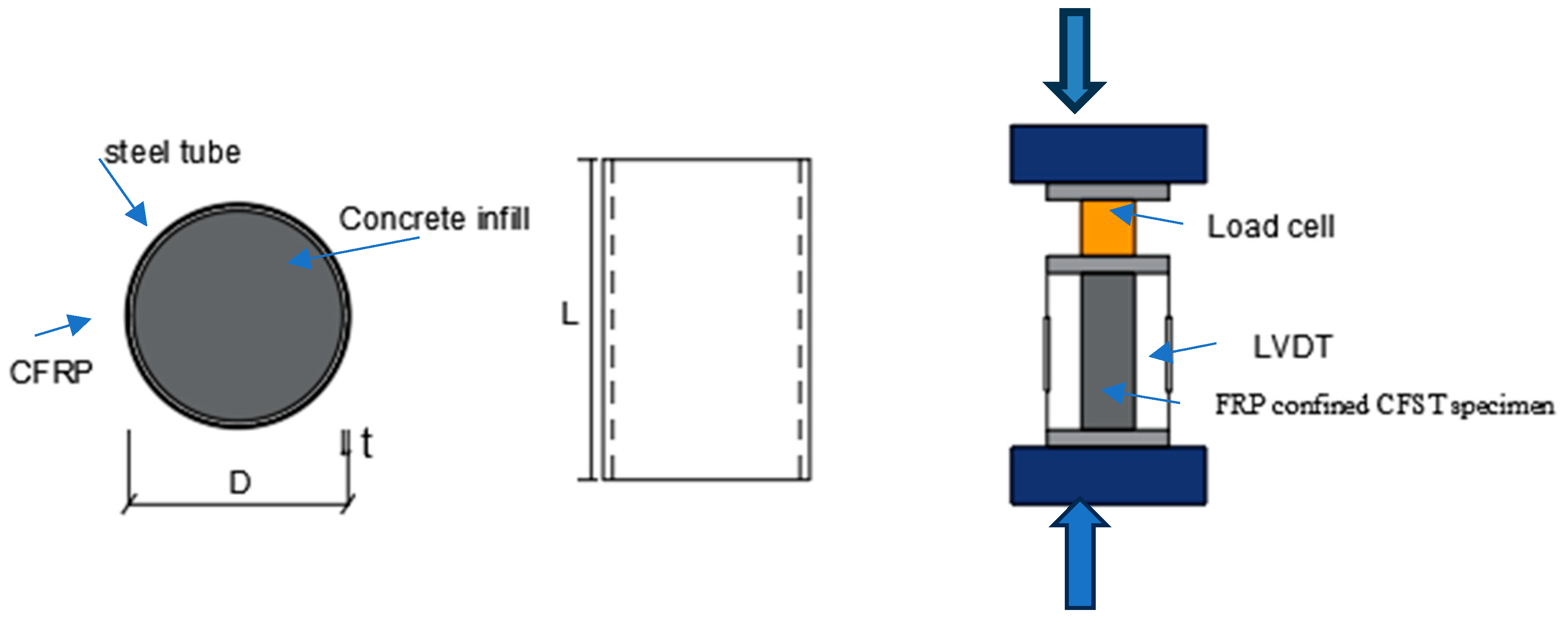
Figure 2.
Concrete-filled steel tube (CFST) specimens tested.
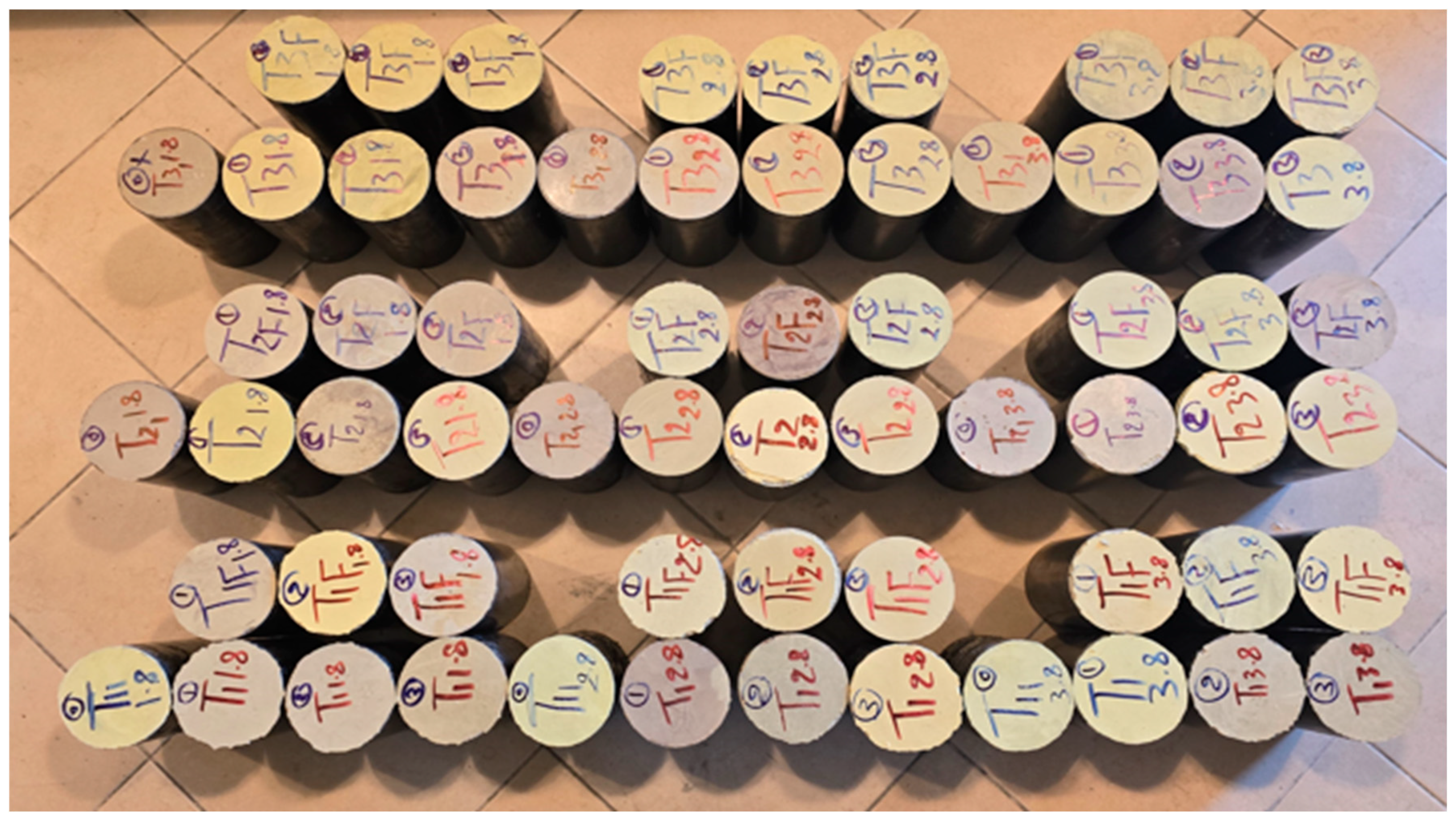
Figure 3.
Typical failure modes of the specimens.
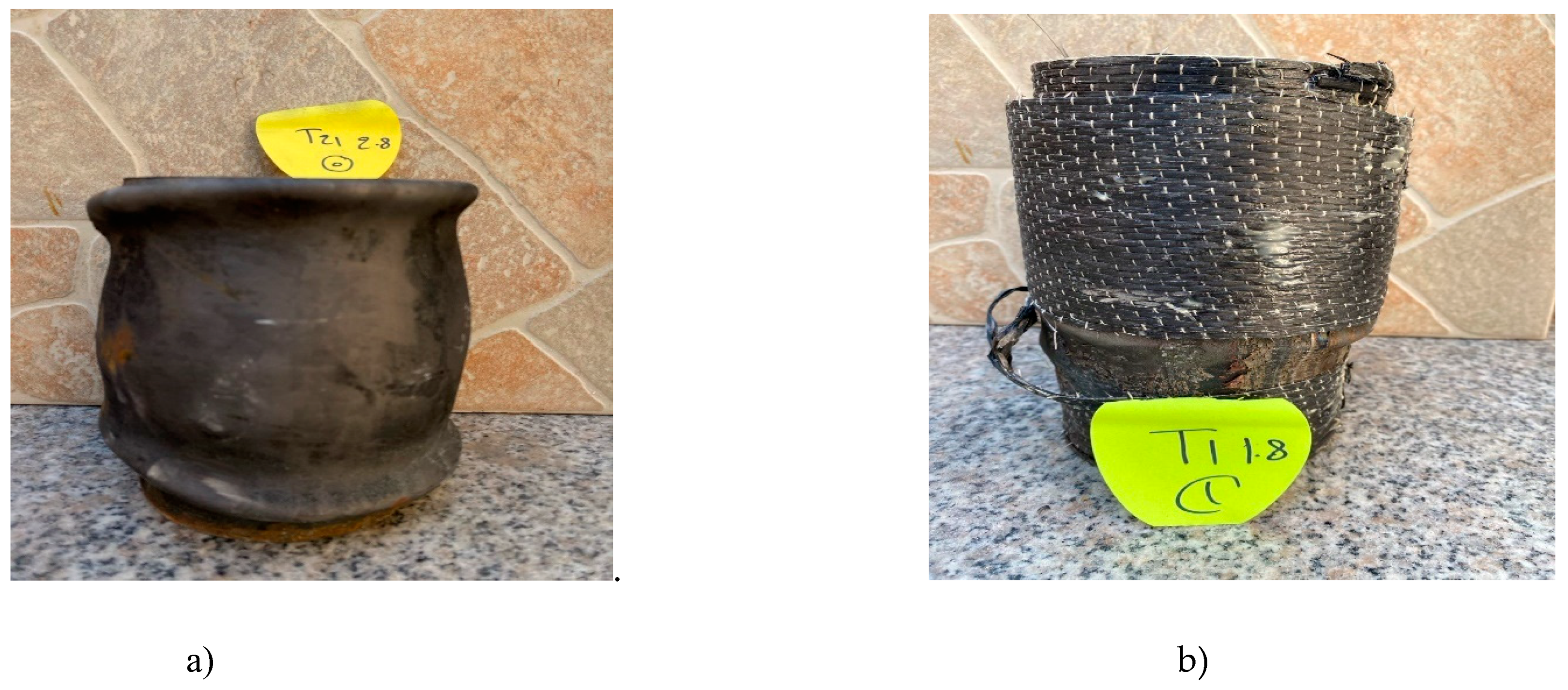
Figure 4.
Examples of axial load vs. axial shortening curves for CFST specimens having different FRP layers (tube thickness of 3.8 mm and infill concrete strength of a) 30 MPa and b) 40 MPa).
Figure 4.
Examples of axial load vs. axial shortening curves for CFST specimens having different FRP layers (tube thickness of 3.8 mm and infill concrete strength of a) 30 MPa and b) 40 MPa).
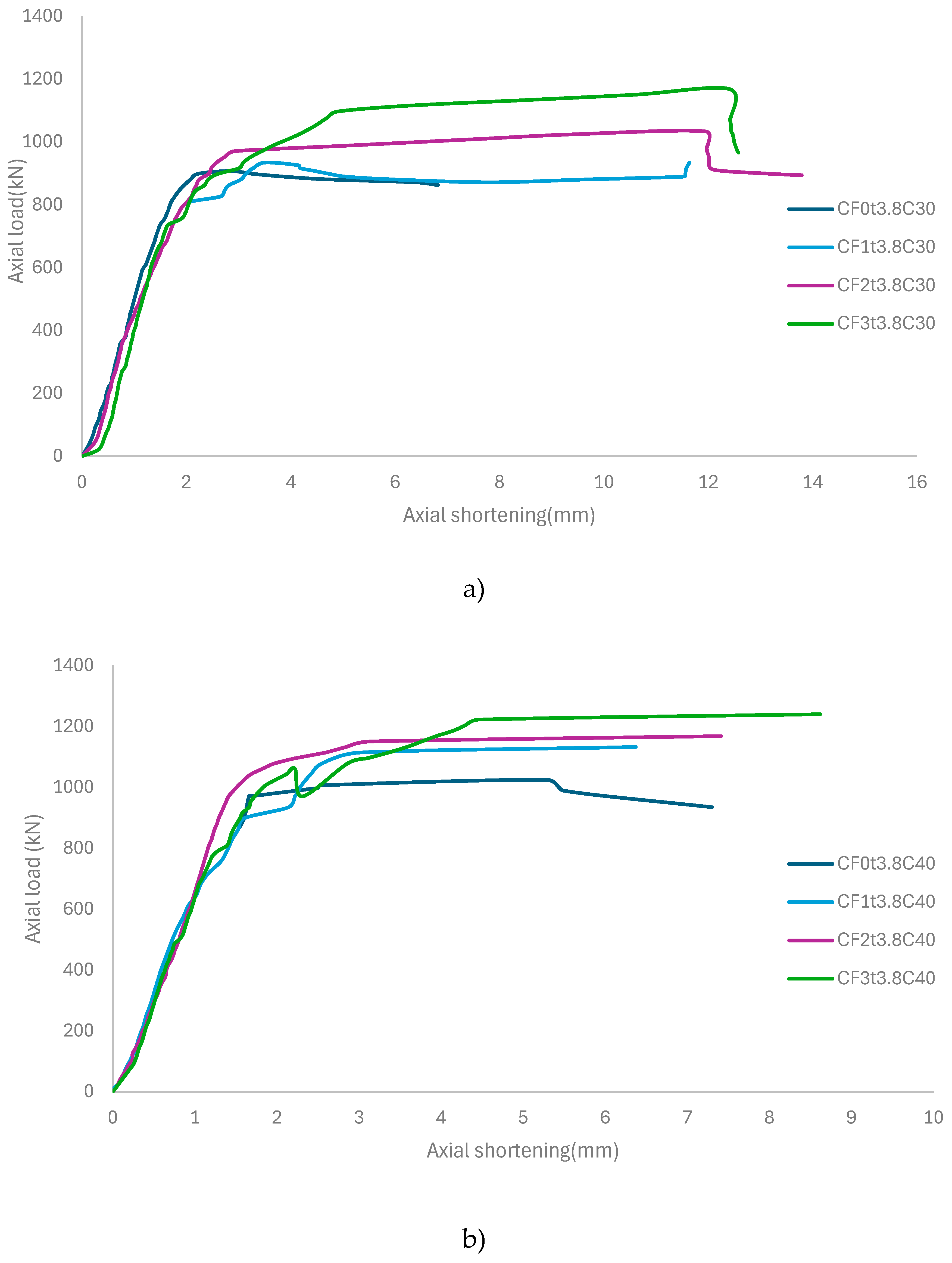
Figure 5.
Effect of the number of FRP layers on the maximum axial load capacity of CFST having different steel tube thickness and concrete strength (without silica slurry and polypropylene fiber).
Figure 5.
Effect of the number of FRP layers on the maximum axial load capacity of CFST having different steel tube thickness and concrete strength (without silica slurry and polypropylene fiber).
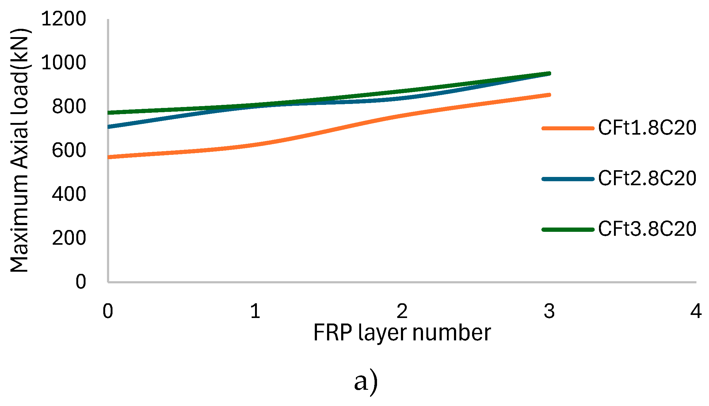
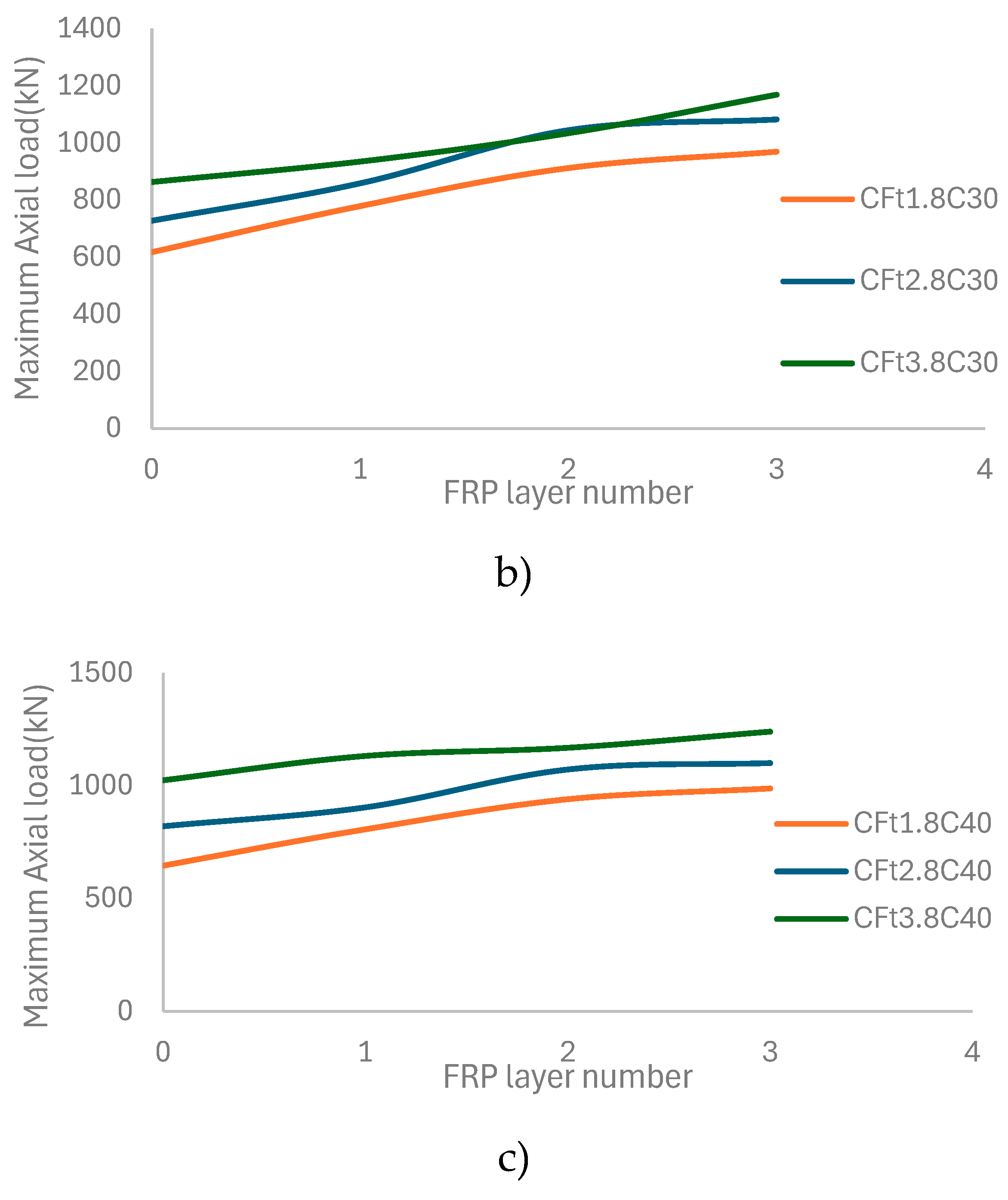
Figure 6.
Effect of the number of FRP layers on the maximum axial load capacity of CFST having different steel tube thickness and concrete strength (with silica slurry and polypropylene fiber).
Figure 6.
Effect of the number of FRP layers on the maximum axial load capacity of CFST having different steel tube thickness and concrete strength (with silica slurry and polypropylene fiber).
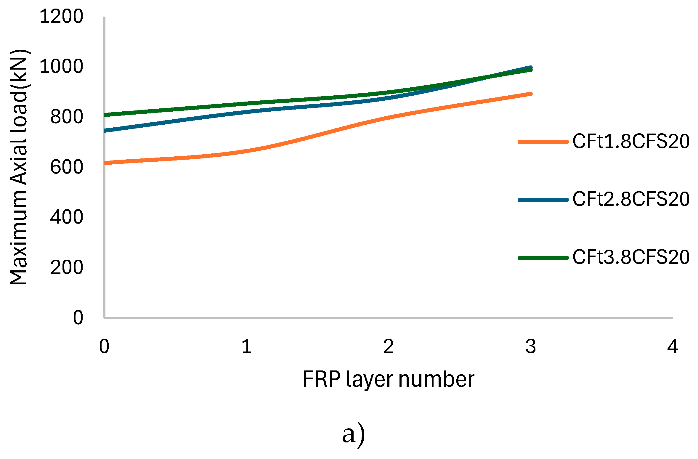
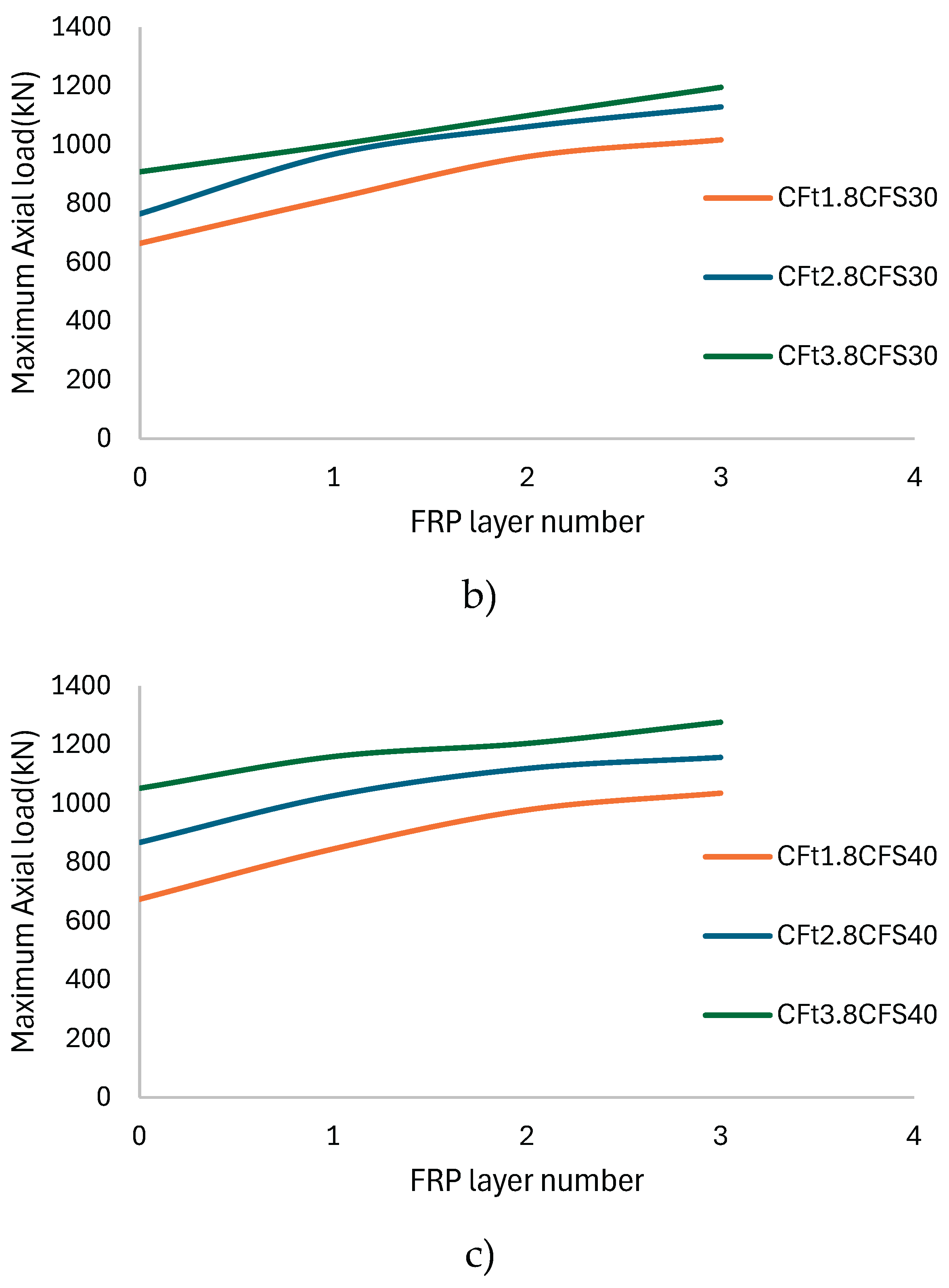
Table 1.
Mix proportions of concrete mixes.
| Mix proportion (kg/m3). | |||||||||
| Gravel (kg/m3) | Sand (kg/m3) | Fine sand (kg/m3) | Cement (kg/m3) | Admixture superplasticizer (SP)%1cement | polypropylene PP Fiber (kg/m3) | Silica fume (kg/m3) | Water (kg/m3) |
w/c Ratio | Concrete class |
| 545.88 | 227.45 | 1197.91 | 272.02 | 2.72024 | 0 | 0 | 114.24 | 0.42 | C20 |
| 545.88 | 232.50 | 1142.31 | 332.67 | 3.32678 | 0 | 0 | 106.45 | 0.32 | C30 |
| 551.40 | 242.61 | 1093.61 | 389.65 | 3.89656 | 0 | 0 | 105.20 | 0.27 | C40 |
| 545.88 | 227.45 | 1197.91 | 272.02 | 2.72024 | 3.0327 | 3.03 | 114.24 | 0.42 | CF20 |
| 545.88 | 232.50 | 1142.31 | 332.67 | 3.32678 | 3.0327 | 3.03 | 106.45 | 0.32 | CF30 |
| 551.40 | 242.61 | 1093.61 | 389.65 | 3.89656 | 3.0327 | 3.03 | 105.20 | 0.27 | CF40 |
Table 2.
Details of the specimen’s group 1.
| Specimens | L (mm) | D (mm) | FRP | nf | ts (mm) |
tf (mm) |
fy (MPa) |
fc (MPa) |
| CF0t1.8C20 | 220 | 110 | CFRP | 0 | 1.8 | 0 | 307 | 19.3 |
| CF1t1.8C20 | 220 | 110 | CFRP | 1 | 1.8 | 0.34 | 307 | 19.3 |
| CF2t1.8C20 | 220 | 110 | CFRP | 2 | 1.8 | 0.34 | 307 | 19.3 |
| CF3t1.8C20 | 220 | 110 | CFRP | 3 | 1.8 | 0.34 | 307 | 19.3 |
| CF0t2.8C20 | 218 | 109 | CFRP | 0 | 2.8 | 0 | 307 | 19.3 |
| CF1t2.8C20 | 218 | 109 | CFRP | 1 | 2.8 | 0.34 | 307 | 19.3 |
| CF2t2.8C20 | 218 | 109 | CFRP | 2 | 2.8 | 0.34 | 307 | 19.3 |
| CF3t2.8C20 | 218 | 109 | CFRP | 3 | 2.8 | 0.34 | 307 | 19.3 |
| CF0t3.8C20 | 214 | 107 | CFRP | 0 | 3.8 | 0 | 307 | 19.3 |
| CF1t3.8C20 | 214 | 107 | CFRP | 1 | 3.8 | 0.34 | 307 | 19.3 |
| CF2t3.8C20 | 214 | 107 | CFRP | 2 | 3.8 | 0.34 | 307 | 19.3 |
| CF3t3.8C20 | 214 | 107 | CFRP | 3 | 3.8 | 0.34 | 307 | 19.3 |
| CF0t1.8CFS20 | 220 | 110 | CFRP | 0 | 1.8 | 0 | 307 | 22.1 |
| CF1t1.8CFS20 | 220 | 110 | CFRP | 1 | 1.8 | 0.34 | 307 | 22.1 |
| CF2t1.8CFS20 | 220 | 110 | CFRP | 2 | 1.8 | 0.34 | 307 | 22.1 |
| CF3t1.8CFS20 | 220 | 110 | CFRP | 3 | 1.8 | 0.34 | 307 | 22.1 |
| CF0t2.8CFS20 | 218 | 109 | CFRP | 0 | 2.8 | 0 | 307 | 22.1 |
| CF1t2.8CFS20 | 218 | 109 | CFRP | 1 | 2.8 | 0.34 | 307 | 22.1 |
| CF2t2.8CFS20 | 218 | 109 | CFRP | 2 | 2.8 | 0.34 | 307 | 22.1 |
| CF3t2.8CFS20 | 218 | 109 | CFRP | 3 | 2.8 | 0.34 | 307 | 22.1 |
| CF0t3.8CFS20 | 214 | 107 | CFRP | 0 | 3.8 | 0 | 307 | 22.1 |
| CF1t3.8CFS20 | 214 | 107 | CFRP | 1 | 3.8 | 0.34 | 307 | 22.1 |
| CF2t3.8CFS20 | 214 | 107 | CFRP | 2 | 3.8 | 0.34 | 307 | 22.1 |
| CF3t3.8CFS20 | 214 | 107 | CFRP | 3 | 3.8 | 0.34 | 307 | 22.1 |
Table 3.
Details of the specimen’s group 2.
| Specimens | L (mm) | D (mm) | FRP | nf | ts (mm) |
tf (mm) |
fy (MPa) |
fc (MPa) |
| CF0t1.8C30 | 220 | 110 | CFRP | 0 | 1.8 | 0 | 307 | 26.8 |
| CF1t1.8C30 | 220 | 110 | CFRP | 1 | 1.8 | 0.34 | 307 | 26.8 |
| CF2t1.8C30 | 220 | 110 | CFRP | 2 | 1.8 | 0.34 | 307 | 26.8 |
| CF3t1.8C30 | 220 | 110 | CFRP | 3 | 1.8 | 0.34 | 307 | 26.8 |
| CF0t2.8C30 | 218 | 109 | CFRP | 0 | 2.8 | 0 | 307 | 26.8 |
| CF1t2.8C30 | 218 | 109 | CFRP | 1 | 2.8 | 0.34 | 307 | 26.8 |
| CF2t2.8C30 | 218 | 109 | CFRP | 2 | 2.8 | 0.34 | 307 | 26.8 |
| CF3t2.8C30 | 218 | 109 | CFRP | 3 | 2.8 | 0.34 | 307 | 26.8 |
| CF0t3.8C30 | 214 | 107 | CFRP | 0 | 3.8 | 0 | 307 | 26.8 |
| CF1t3.8C30 | 214 | 107 | CFRP | 1 | 3.8 | 0.34 | 307 | 26.8 |
| CF2t3.8C30 | 214 | 107 | CFRP | 2 | 3.8 | 0.34 | 307 | 26.8 |
| CF3t3.8C30 | 214 | 107 | CFRP | 3 | 3.8 | 0.34 | 307 | 26.8 |
| CF0t1.8CFS30 | 220 | 110 | CFRP | 0 | 1.8 | 0 | 307 | 30.1 |
| CF1t1.8CFS30 | 220 | 110 | CFRP | 1 | 1.8 | 0.34 | 307 | 30.1 |
| CF2t1.8CFS30 | 220 | 110 | CFRP | 2 | 1.8 | 0.34 | 307 | 30.1 |
| CF3t1.8CFS30 | 220 | 110 | CFRP | 3 | 1.8 | 0.34 | 307 | 30.1 |
| CF0t2.8CFS30 | 218 | 109 | CFRP | 0 | 2.8 | 0 | 307 | 30.1 |
| CF1t2.8CFS30 | 218 | 109 | CFRP | 1 | 2.8 | 0.34 | 307 | 30.1 |
| CF2t2.8CFS30 | 218 | 109 | CFRP | 2 | 2.8 | 0.34 | 307 | 30.1 |
| CF3t2.8CFS30 | 218 | 109 | CFRP | 3 | 2.8 | 0.34 | 307 | 30.1 |
| CF0t3.8CFS30 | 214 | 107 | CFRP | 0 | 3.8 | 0 | 307 | 30.1 |
| CF1t3.8CFS30 | 214 | 107 | CFRP | 1 | 3.8 | 0.34 | 307 | 30.1 |
| CF2t3.8CFS30 | 214 | 107 | CFRP | 2 | 3.8 | 0.34 | 307 | 30.1 |
| CF3t3.8CFS30 | 214 | 107 | CFRP | 3 | 3.8 | 0.34 | 307 | 30.1 |
Table 4.
Details of the specimen’s group 3.
| Specimens | L (mm) | D (mm) | FRP | nf | ts (mm) |
tf (mm) |
fy (MPa) |
fc (MPa) |
| CF0t1.8C40 | 220 | 110 | CFRP | 0 | 1.8 | 0 | 307 | 35.8 |
| CF1t1.8C40 | 220 | 110 | CFRP | 1 | 1.8 | 0.34 | 307 | 35.8 |
| CF2t1.8C40 | 220 | 110 | CFRP | 2 | 1.8 | 0.34 | 307 | 35.8 |
| CF3t1.8C40 | 220 | 110 | CFRP | 3 | 1.8 | 0.34 | 307 | 35.8 |
| CF0t2.8C40 | 218 | 109 | CFRP | 0 | 2.8 | 0 | 307 | 35.8 |
| CF1t2.8C40 | 218 | 109 | CFRP | 1 | 2.8 | 0.34 | 307 | 35.8 |
| CF2t2.8C40 | 218 | 109 | CFRP | 2 | 2.8 | 0.34 | 307 | 35.8 |
| CF3t2.8C40 | 218 | 109 | CFRP | 3 | 2.8 | 0.34 | 307 | 35.8 |
| CF0t3.8C40 | 214 | 107 | CFRP | 0 | 3.8 | 0 | 307 | 35.8 |
| CF1t3.8C40 | 214 | 107 | CFRP | 1 | 3.8 | 0.34 | 307 | 35.8 |
| CF2t3.8C40 | 214 | 107 | CFRP | 2 | 3.8 | 0.34 | 307 | 35.8 |
| CF3t3.8C40 | 214 | 107 | CFRP | 3 | 3.8 | 0.34 | 307 | 35.8 |
| CF0t1.8CFS40 | 220 | 110 | CFRP | 0 | 1.8 | 0 | 307 | 39.8 |
| CF1t1.8CFS40 | 220 | 110 | CFRP | 1 | 1.8 | 0.34 | 307 | 39.8 |
| CF2t1.8CFS40 | 220 | 110 | CFRP | 2 | 1.8 | 0.34 | 307 | 39.8 |
| CF3t1.8CFS40 | 220 | 110 | CFRP | 3 | 1.8 | 0.34 | 307 | 39.8 |
| CF0t2.8CFS40 | 218 | 109 | CFRP | 0 | 2.8 | 0 | 307 | 39.8 |
| CF1t2.8CFS40 | 218 | 109 | CFRP | 1 | 2.8 | 0.34 | 307 | 39.8 |
| CF2t2.8CFS40 | 218 | 109 | CFRP | 2 | 2.8 | 0.34 | 307 | 39.8 |
| CF3t2.8CFS40 | 218 | 109 | CFRP | 3 | 2.8 | 0.34 | 307 | 39.8 |
| CF0t3.8CFS40 | 214 | 107 | CFRP | 0 | 3.8 | 0 | 307 | 39.8 |
| CF1t3.8CFS40 | 214 | 107 | CFRP | 1 | 3.8 | 0.34 | 307 | 39.8 |
| CF2t3.8CFS40 | 214 | 107 | CFRP | 2 | 3.8 | 0.34 | 307 | 39.8 |
| CF3t3.8CFS40 | 214 | 107 | CFRP | 3 | 3.8 | 0.34 | 307 | 39.8 |
Table 5.
Ultimate axial load of CFST columns.
| Specimens | Nu (kN) | Specimens | Nu (kN) | Specimens | Nu (kN) |
| CF0t1.8C20 | 570 | CF0t1.8C30 | 617 | CF0t1.8C40 | 646 |
| CF1t1.8C20 | 627 | CF1t1.8C30 | 779 | CF1t1.8C40 | 807 |
| CF2t1.8C20 | 760 | CF2t1.8C30 | 912 | CF2t1.8C40 | 940 |
| CF3t1.8C20 | 855 | CF3t1.8C30 | 969 | CF3t1.8C40 | 988 |
| CF0t2.8C20 | 709 | CF0t2.8C30 | 728 | CF0t2.8C40 | 821 |
| CF1t2.8C20 | 802 | CF1t2.8C30 | 858 | CF1t2.8C40 | 905 |
| CF2t2.8C20 | 839 | CF2t2.8C30 | 1045 | CF2t2.8C40 | 1073 |
| CF3t2.8C20 | 951 | CF3t2.8C30 | 1082 | CF3t2.8C40 | 1101 |
| CF0t3.8C20 | 773 | CF0t3.8C30 | 863 | CF0t3.8C40 | 1025 |
| CF1t3.8C20 | 809 | CF1t3.8C30 | 935 | CF1t3.8C40 | 1132 |
| CF2t3.8C20 | 872 | CF2t3.8C30 | 1034 | CF2t3.8C40 | 1168 |
| CF3t3.8C20 | 953 | CF3t3.8C30 | 1169 | CF3t3.8C40 | 1240 |
| CF0t1.8CFS20 | 617 | CF0t1.8CFS30 | 665 | CF0t1.8CFS40 | 674 |
| CF1t1.8CFS20 | 665 | CF1t1.8CFS30 | 817 | CF1t1.8CFS40 | 845 |
| CF2t1.8CFS20 | 798 | CF2t1.8CFS30 | 959 | CF2t1.8CFS40 | 978 |
| CF3t1.8CFS20 | 893 | CF3t1.8CFS30 | 1016 | CF3t1.8CFS40 | 1035 |
| CF0t2.8CFS20 | 746 | CF0t2.8CFS30 | 765 | CF0t2.8CFS40 | 867 |
| CF1t2.8CFS20 | 821 | CF1t2.8CFS30 | 989 | CF1t2.8CFS40 | 1026 |
| CF2t2.8CFS20 | 877 | CF2t2.8CFS30 | 1091 | CF2t2.8CFS40 | 1119 |
| CF3t2.8CFS20 | 998 | CF3t2.8CFS30 | 1129 | CF3t2.8CFS40 | 1157 |
| CF0t3.8CFS20 | 809 | CF0t3.8CFS30 | 908 | CF0t3.8CFS40 | 1052 |
| CF1t3.8CFS20 | 854 | CF1t3.8CFS30 | 962 | CF1t3.8CFS40 | 1159 |
| CF2t3.8CFS20 | 899 | CF2t3.8CFS30 | 1070 | CF2t3.8CFS40 | 1204 |
| CF3t3.8CFS20 | 989 | CF3t3.8CFS30 | 1195 | CF3t3.8CFS40 | 1276 |
Disclaimer/Publisher’s Note: The statements, opinions and data contained in all publications are solely those of the individual author(s) and contributor(s) and not of MDPI and/or the editor(s). MDPI and/or the editor(s) disclaim responsibility for any injury to people or property resulting from any ideas, methods, instructions or products referred to in the content. |
© 2025 by the authors. Licensee MDPI, Basel, Switzerland. This article is an open access article distributed under the terms and conditions of the Creative Commons Attribution (CC BY) license (https://creativecommons.org/licenses/by/4.0/).
Copyright: This open access article is published under a Creative Commons CC BY 4.0 license, which permit the free download, distribution, and reuse, provided that the author and preprint are cited in any reuse.


