
Submitted:
20 October 2025
Posted:
21 October 2025
You are already at the latest version
Abstract
Stroke rehabilitation exoskeletons require joint mechanisms capable of replicating physiological stiffness modulation to adapt to accommodate varying gait phases. This paper presents a novel compact variable stiffness mechanism (VSM) for knee exoskel-etons, based on a simplified three-bar linkage topology. The proposed design achieves a tunable quasi-stiffness range of 0.15–2.0 NM/deg. Static characterization under a 2kg load demonstrated up to 23.0N of collision force attenuation in softening regimes (λ< 2.3)through passive viscoelastic dissipation, whereas hardening behavior (λ≥2.3) pre-served precise torque-angle characteristics scalable to physiological loading. Parametric analysis showed an 89% correlation between theoretical and scaled experimental stiff-ness profiles for values from 0.5 to 2.5. The proposed architecture enables decoupled optimization of impact safety and positional precision, offering a clinically adaptable solution for hemiparetic gait assistance.
Keywords:
variable stiffness mechanism
; knee exoskeleton
; exoskeleton design
; hemiparetic gait rehabilitation
1. Introduction
Accelerated population aging and urbanization have precipitated a discernible escalation in the prevalence of stroke risk factors, concomitantly led to a marked increase burden of stroke-related disability, particularly in China [1]. Post-stroke hemiplegia and gait abnormalities constitute primary motor dysfunctions among stroke survivors, representing predominant determinants adversely impacting activities of daily living and quality of life [2,3]. Post-stroke rehabilitation is a progressive, dynamic process aimed at restoring physical, cognitive, motional, communicative, and social functions. Substantial clinical evidence demonstrates that integrating physical rehabilitation with task-oriented functional training can greatly enhance potentiates post stroke functional recovery [4]. For non-ambulatory patients, robotic-assisted gait training combined with physical therapy has been shown to enhance the probability of regaining independent ambulation [5].
Over the past decade, numerous robotic systems and control strategies for gait rehabilitation have been developed [6]. In clinical rehabilitation setting, treadmill-based exoskeletons -such as PMA [7], ALEX [8], LOPES [9], and C-Mill [10] systems enable repetitive, task-specific locomotor training during the early recovery phase. For community-based or home rehabilitation, wearable exoskeletons must be lightweight, safe, and easy to don and doff while providing effective overground gait assistance.
Many portable lower-limb have been proposed [11,12,13,14,15]. However, most employ fixed-stiffness joints, which limit adaptability due to inter-subject variability in gait speed and joint stiffness [16,17]. This limitation highlights the importance of implementing variable stiffness mechanisms (VSMs), which allow mechanical adaptation to different gait phases. In general, VSMs achieve stiffness modulation by altering the characteristics of springs—such as effective length or pretension force [18]. Bio-inspiration underpins designs emulating the antagonistic action of musculoskeletal systems, incorporating spring pretension adjustment to modify stiffness settings [19]. T. Noda [20] devised an upper-limb exoskeleton employing dual pneumatic artificial muscles generating antagonistic contractile forces to actuate joints. Subsequent scholars achieved concurrent joint positioning and stiffness modulation via independent motors, thereby reducing actuator footprint and mass. Notable implementations include the MACCEPA [21], MACCEPA 2.0 [22], VS-joint [23], FSJ [24], SJM I [25], and SJM II [26] architectures. Recently, Li et al [27] introduced a modular, reconfigurable VSMs based on a four- bar linkage, and Bowden-cable actuation, enabling stiffness adjustment through changes the spring preload. Building upon this foundation, this study proposes a compact VSM specifically optimized for knee exoskeleton applications. Based on a three-bar linkage mechanism, it employs the ratio of output to input link lengths as the key kinematic variable for stiffness adjustment. By modulating this link ratio parameter, the mechanism can switch between softening and stiffening behavior modes, enabling phase-adaptive impedance matching with biological knee dynamics throughout the gait cycle. Compared to fixed-stiffness actuators, this approach offers significant advantages: the softening mode enhances shock absorption during external impacts, improving safety in human-machine interactions, while the stiffening mode increases gait cycle stability and reduces metabolic expenditure. Furthermore, the lever ratio-based control scheme decouples stiffness adjustment from position control, simplifying stiffness variation implementation while maintaining mechanical simplicity. Key contributions of this study include: (i) a novel mechanical design tailored to joint dimensions and biomechanical constraints; (ii) a mathematical model defining input-output lever ratio constraints and stiffness boundaries; (iii) static and dynamic characterization of the VSM prototype; (iv) modularization of the VSM for seamless integration into knee exoskeleton systems for gait rehabilitation in hemiplegic patients.
The remainder of the paper is organized as follows. Section II reviews relevant literature and introduces the link length ratio parameter in the proposed mechanism. Section III presents the mechanical design, modeling, and prototype implementation. Section IV reports experimental results from static testing. Section V discusses the findings and Section VI concludes the paper.
2. Mechanical Design of VSM
2.1. Basic Principles of Stiffness Variation
The variable stiffness mechanism (VSM) proposed in this paper builds on the linkage concept of Li and Bai [27]. In this study, the completeness of this concept is briefly reiterated and the parameters are optimized for subsequent mechanical design. The mechanism is simplified from a four-bar linkage to a compact three-link architecture tailored for knee-exoskeleton integration, as illustrated in Figure 1(a)-(b), rod-1 (input-link) and rod-3 (output-link) are mounted to the base via revolute joints, while the elastic rod-2 (a spring-coupled element) connects the distal ends of rod-1 and rod-3. The spring-coupled unit provides a tunable viscoelastic path between the two links, enabling stiffness modulation without adding bulk actuators to the joint. The torque generated at the output link of arises from the elastic force in the spring-coupled unit transmitted through the linkage Jacobian :
With
The Jacobian characterizes the instantaneous rate of change of the spring length with respect to the angular displacement between links and . Here, denotes the position vector from the pivot point to the spring attachment point (with magnitude ), and represents the unit direction vector along the spring axis. The term corresponds to the differential change in spring length due to angular variation . Furthermore, the Jacobian can be expressed in the following form:
is provided by the spring-coupled element, satisfying Hooke’s law:
where is the original length of when the angle between and is 0, is the spring change amount, and is the pretension of elastic element when .
Joint stiffness is related to , which is derived from the differential of (1):
Substituting (4) into (5) and rearranging it, we can obtain the equivalent stiffness related to and the spring preload :
We can observe that the equivalent stiffness in (6) is mathematically partitioned into two distinct components, which is caused by the spring coupling mechanism and the preload force provided by the spring.
For convenience of study, we introduce the ratio of input-rod length to output-rod length and specify that is adjustable, then , and rearrange (3) to obtain:
and the differentiation of with respect to yields:
When the angle between and is 0, the initial length of the spring coupling unit is:
Note that ,
2.2. Analysis of the Proposed VSM
Parametric optimization of the variable stiffness actuator (VSA) requires a comprehensive analysis of its characteristics to establish design constraints. By strategically simplifying the equations under specific kinematic conditions—specifically, an initial inter-link angle of and the length configuration where —the equivalent stiffness in (6) becomes analytically decoupled from the spring preload force :
This essential simplification occurs because the configuration negates the effects of spring deformation, thereby eliminating terms dependent on in the stiffness expression.
When , in order to keep the preload , we do not consider the contribution of the compression spring in the spring coupling unit, Figure 2 shows and initial angle is not 0:
where .Here, denotes the initial angle between link and , and represents the relative angular displacement induced during the actuation of . The angle can be derived as follows:
Conversely, when , a non-zero preload force is applied, initial angle for and , stiffness same as (6).
Critically, equation (11) demonstrates that the equivalent stiffness is exclusively determined by the parameters and . This section systematically investigates how these parameters shape the stiffness characteristics. As illustrated in Figure 3(a), the output torque of the VSM increases monotonically with rising values of as well as . Figure 3(b) further partitions the domain into three distinct regimes, corresponding to hardening behavior, softening behavior, and negative stiffness. Specifically, joint stiffening refers to the enhancement of equivalent stiffness under deformation, whereas softening denotes a reduction in stiffness responsiveness.
Parametric analysis indicates that serves as the principal regulator of joint stiffness properties. By strategically tuning , a variety of stiffness regimes can be engineered. For our analysis, —which has an initial value of 2.3 and is tunable up to 2.5—serves as the principal parameter for regulating joint stiffness. A reduced compresses the range of softening behavior but simultaneously elevates at low .When the condition is satisfied, the system stiffness formulation additionally incorporates a preload force, as reflected in (6). Notably, Figure 3 shows a pronounced increase in both joint torque and stiffness once .
Moreover, the configuration induces a spring-dominant mode of stiffness modulation, as formalized in (12) and (13). Figure 4 provides a quantitative depiction of the coupled evolution of torque and stiffness with respect to and . As illustrated in Figure 4, the system torque exhibits a pronounced positive correlation with both the angle and the spring constant . Furthermore, the rates of change of both the output torque and the system stiffness increase significantly with higher values of , indicating enhanced sensitivity of the system’s stiffness response under greater spring constants.
and different Rod length ratio on VSM output-torque . (b) Stiffness performance affected by and with , .
and different stiffness on VSM output-torque and (b) Stiffness performance affected by and with , .
2.3. Structure Design and Prototype
The physical prototype, shown in Figure 6, integrates three primary subsystems: a drive module, the variable stiffness mechanism, and an output measurement module.
As illustrated in Figure 5(a), when , a zero-preload initial angle is established between the input and output rods, yielding a zero-preload condition within the spring unit—consistent with the analytical formulation in (13). Under conditions which or , the three-bar linkage assumes a collinear configuration, with a preload force being introduced exclusively when . Figure 5(b) further illustrates the operational states of the VSM under varying deflection angles for and , where spring elongation progressively generates output torque.
The drive module consists of a position-controlled servo motor, which is realized as an integrated electromechanical assembly combining a brushless DC motor, a harmonic reducer, an optical encoder, and dedicated servo drive electronics. The actuator is mounted onto the experimental platform via precision-machined brackets, providing controlled torque and positional input to the VSM. Command signals are regulated through a host computer, while rigid coupling interfaces at both termini ensure precise kinematic alignment among all subsystems.
Leveraging the previously established principle of variable stiffness modulation, a reconfigurable VSM was developed comprising three functional stages. As shown in the enlarged view in Figure 6, the input stage employs planetary reduction gearing with three radially arranged linkages serving as input rods. The spring-coupling stage directly connects the input and output shafts, while the output stage incorporates an adjustable T-nut that enables manual modulation of link length. Spring characteristics can be further tailored either by substituting elastic elements of varying stiffness or by reducing the number of parallel springs coupled between the shafts. Through Manual adjustment of the T-nut pivot enables operational mode transitions between softening stiffness regimes () and stiffening regimes (). The principal design parameters of the prototype are summarized in Table 1.
An experimental platform was constructed to evaluate the VSM’s performance in terms of stiffness identification, collision safety assessment, and trajectory tracking validation. The testbed configuration is depicted in Figure 7. A linearized automatic control scheme was implemented to regulate motor rotation angles, serving as a biomechanically validated alternative to conventional manual leg oscillation protocols. The VSM prototype’s input shaft is driven by a 57-mm frame brushless DC motor (Dinotec DT57BL70-230) through a Joyland PLF60 proportional planetary gearbox (20:1 reduction ratio). A reaction pendulum, mechanically linked to the output shaft via an HLT-151 torque transducer ( Nm accuracy), enables controlled torque measurement. Angular displacement is measured with resolution using an Oid-Encoder OID-R3806D absolute encoder mounted on the pendulum axis. All actuators and sensors are interfaced with a host computer through shielded communication cables, allowing centralized monitoring and control via an integrated human-machine interface (HMI).
Through systematic parameter optimization on the developed platform, the spring configuration cataloged in Table 2 was selected.
3. Experimental Evaluation
To experimentally validate these findings, quasi-static experiments were conducted to characterize the torque-deflection behavior of the mechanism prototype. Five experimental cases were considered, as illustrated in Figure 5(a). Physical implementation of each case can be achieved by manually adjusting the T-nut on output rod . Three cases were primarily discussed: Cases 1, 2, and 3 correspond to scenarios, while Cases 4 and 5 correspond to collinear configurations of , , and . Specifically, Case 4 satisfies , whereas Case 5 satisfies , resulting in a preload condition within the spring. For each trial, torque was applied either by offsetting the output shaft of the pendulum prototype or by direct actuation from the input motor. The torque and deflection data were simultaneously acquired through integrated sensors.
The experimental results are comprehensively summarized in the accompanying figures. Figure 8(a) illustrates the torque reflection relationship for a configuration with and = 2.5N/mm across different rod length ratios. Similarly, Figure 8(b) depicts the corresponding torque reflection curves under altered parameters (,= 4.3N/mm), further validating the reliability of the proposed mechanism. Comparative analyses between theoretical stiffness predictions and experimentally derived stiffness values, the latter obtained via post-processing of measured data, are presented in Figure 9. Finally, oscillation tests were performed by applying precisely controlled torques to the oscillating components; representative results from these tests are shown in Figure 10.
4. Discussion
The experimental characterization of the VSM successfully validated its core mechanical principles and performance. The close agreement between theoretical predictions and measured torque-displacement data (Figure 8), with a maximum error of N ·mm, confirms the accuracy of the established mathematical model for the three-link, lever-based design.
Parametric analysis revealed that the rod-length ratio () is the dominant factor in shaping the mechanism’s stiffness behavior. Specifically:
- Low regimes () produced a softening stiffness profile, characterized by high positional accuracy (error under loads 5 Nm). This regime also demonstrated effective passive energy dissipation, absorbing up to 0.8 J during impact events, which is a critical feature for operational safety.
- High regimes () induced a pronounced hardening stiffness behavior, where joint stiffness increased monotonically with deflection. This design enables the joint to provide substantial mechanical resistance under high loads.
The mechanism’s dynamic performance was further quantified through swing testing. As shown in Figure 10, experimental hysteresis loops closely conformed to theoretical predictions, despite peak deviations of N · mm caused by backlash in the planetary gearset. The tests confirmed that increasing the spring preload force (F₀) effectively amplifies the intensity of the hardening behavior, generating high stiffness gradients up to .
Despite the strong overall performance, the analysis identified two key mechanical limitations:
- Transient Torque Oscillations: At the initial 5° of angular displacement, peak errors reached 11%, primarily attributed to static friction breakaway at the shaft-housing interface. First item;
- Sustained Motion Error: Beyond the initial transient, a smaller sustained error (~8%) persisted, largely caused by stick-slip vibrations during continuous motion.
Beyond these mechanical limitations, this study is situated within a specific development phase, which presents broader scope limitations. Most notably, the current work has not yet incorporated automation in the testing procedure, lacks full system integration with a human-in-the-loop controller, and has not been validated through large-scale clinical trials. To address these aspects, our immediate research roadmap will focus on:
(1) developing an automated testing framework to enhance protocol consistency and efficiency;
(2) implementing and validating a robust control system that integrates real-time human input;
(3) initiating pilot clinical studies to benchmark performance against established physiological benchmarks.
In summary, this investigation presents a novel structural design for a compact, variable-stiffness exoskeletal joint. Its principal contribution lies in a compliant joint architecture that enables significant stiffness modulation through straightforward manual reconfiguration of the rod-length ratio () and spring constant (). The ability to switch among softening, linear, and stiffening regimes makes the mechanism highly adaptable for a wide range of operational requirements in robotic systems. Future work will focus on implementing automated parameter adjustment and mitigating transient friction effects through optimized surface coatings and bearing selections.
5. Conclusions
This study established a biomimetic variable stiffness joint (VSM) paradigm derived from a simplified three-bar mechanism with tunable rod length ratio . Experimental and theoretical analyses confirmed that the proposed structure enables distinct softening and stiffening behaviors, thereby validating its feasibility as a variable stiffness actuator. The novel VSM functions effectively either as a passive actuator or a flexible drive unit when coupled with electric motors, making it directly applicable to rehabilitation and assistive robotics, particularly for knee orthoses. Beyond validating stiffness modulation performance, the results highlight the potential of the VSM to enhance joint stability, collision safety, and energy efficiency in human–robot interaction. Future work will focus on case studies for modular robotic joints, targeting quantitative knee stiffness requirements during ambulation and emphasizing phase-dependent stiffness adaptation across gait cycle transitions.
Author Contributions
Conceptualization, G.S; methodology, G.S. and Z.G.; software, Z.Z.; validation, Z.G.; formal analysis, G.S.; investigation, G.S., Z.G. and Z.Z.; resources, G.S.; data curation, Z.G.; writing—original draft preparation, Z.G.; writing—review and editing, G.S. and Z.Z.; supervision, G.S.; project administration, G.S. All authors have read and agreed to the published version of the manuscript.
Funding
This research received no external funding
Data Availability Statement
The data presented in this study are available on request from the corresponding author. The data are not publicly available due to privacy restrictions.
Acknowledgments
The authors would like to thank Prof. Xuping Zhang from Aarhus University for his valuable discussions and technical suggestions.
Conflicts of Interest
The authors declare no conflicts of interest.
Abbreviations
The following abbreviations are used in this manuscript:
VSM variable stiffness mechanism
HMI human-machine interface
References
- W. J. Tu, L. D. Wang, and on behalf of the Special Writing Group of China Stroke Surveillance Report, “China stroke surveillance report 2021,” Military Med. Res., vol. 10, p. 33, 2023. [CrossRef]
- C. Liang, C. Wan, J. Yang, et al., “Effect of the Kickstart exoskeleton lower extremity walking system on improving lower extremity walking ability in subacute stroke patients: A randomized controlled trial,” J. NeuroEng. Rehabil., vol. 22, p. 155, 2025. [CrossRef]
- B. T. Cleland, M. Kim, and S. Madhavan, “The relation between hemiparetic gait patterns and walking function after stroke, as measured with wearable sensors,” Ann. Biomed. Eng., vol. 53, pp. 1890–1902, 2025. [CrossRef]
- G. J. Hankey, “Stroke,” Lancet, vol. 389, no. 10069, pp. 641–654, Feb. 2017. [CrossRef]
- A. Barrera Sánchez, et al., “State of the art review of active and passive knee orthoses,” *Machines*, vol. 10, no. 10, p. 865, Oct. 2022. [CrossRef]
- J. Cao, S. Q. Xie, R. Das, and G. L. Zhu, “Control strategies for effective robot assisted gait rehabilitation: The state of art and future prospects,” Med. Eng. Phys., vol. 36, no. 12, pp. 1555–1566, Dec. 2014. [CrossRef]
- S. Hussain, S. Q. Xie, P. K. Jamwal, and J. Parsons, “An intrinsically compliant robotic orthosis for treadmill training,” Med. Eng. Phys., vol. 34, no. 10, pp. 1448–1453, Dec. 2012. [CrossRef]
- S. K. Banala, S. H. Kim, S. K. Agrawal, and J. P. Scholz, “Robot assisted gait training with active leg exoskeleton (ALEX),” IEEE Trans. Neural Syst. Rehabil. Eng., vol. 17, no. 1, pp. 2–8, Feb. 2009. [CrossRef]
- E. H. van Asseldonk and H. van der Kooij, “Robot-aided gait training with LOPES,” in Neurorehabilitation Technology, 2nd ed. London, U.K.: Springer, 2016, pp. 461–481. [CrossRef]
- G. J. Androwis, A. Gaite, A. Engler, G. H. Yue, and J. DeLuca, “The effects of robotic exoskeleton gait training on improving walking adaptability in persons with MS,” in Proc. 2024 46th Annu. Int. Conf. IEEE Eng. Med. Biol. Soc. (EMBC), Orlando, FL, USA, 2024, pp. 1-4. [CrossRef]
- B. Hu, et al., “Stiffness optimal modulation of a variable stiffness energy storage hip exoskeleton and experiments on its assistance effect,” IEEE Trans. Neural Syst. Rehabil. Eng., vol. 31, pp. 1045–1055, 2023. [CrossRef]
- M. Talaty, A. Esquenazi, and J. E. Briceno, “Differentiating ability in users of the ReWalk™ powered exoskeleton: An analysis of walking kinematics,” in Proc. IEEE 13th Int. Conf. Rehabil. Robot., Seattle, WA, USA, Jun. 2013, pp. 1–5. [CrossRef]
- H. Yu, et al., “A new single-leg lower-limb rehabilitation robot: Design, analysis and experimental evaluation,” Machines, vol. 11, no. 4, p. 447, Apr. 2023. [CrossRef]
- B. Sarani and H. Ahmadi, “Mechanical design and control of a novel variable impedance actuator (VIA) for knee joint of a rehabilitation exoskeleton,” *J. Braz. Soc. Mech. Sci. Eng.*, vol. 44, no. 3, p. 81, Mar. 2022. [CrossRef]
- J. Tabucol, et al., “The MyFlex-ζ foot: A variable stiffness ESR ankle-foot prosthesis,” IEEE Trans. Neural Syst. Rehabil. Eng., vol. 33, pp. 653–663, Feb. 2025. [CrossRef]
- A. R. Akl, A. Baca, J. Richards, and F. Conceição, “Leg and lower limb dynamic joint stiffness during different walking speeds in healthy adults,” Gait Posture, vol. 82, pp. 294–300, Oct. 2020. [CrossRef]
- K. Wang, et al., “The fundamental property of human leg during walking: Linearity and nonlinearity,” IEEE Trans. Neural Syst. Rehabil. Eng., vol. 31, pp. 4871–4881, 2023. [CrossRef]
- L. Liu, S. Leonhardt, C. Ngo, and B. J. Misgeld, “Impedance-controlled variable stiffness actuator for lower limb robot applications,” IEEE Trans. Autom. Sci. Eng., vol. 17, no. 2, pp. 991–1004, Apr. 2020. [CrossRef]
- S. A. Migliore, E. A. Brown, and S. P. DeWeerth, “Biologically inspired joint stiffness control,” in Proc. IEEE Int. Conf. Robot. Autom., Barcelona, Spain, Apr. 2005, pp. 4508–4513. [CrossRef]
- T. Noda, T. Teramae, B. Ugurlu, and J. Morimoto, “Development of an upper limb exoskeleton powered via pneumatic electric hybrid actuators with Bowden cable,” in Proc. IEEE/RSJ Int. Conf. Intell. Robots Syst., Chicago, IL, USA, Sep. 2014, pp. 3573–3578. [CrossRef]
- R. Van Ham, et al., “MACCEPA, the mechanically adjustable compliance and controllable equilibrium position actuator: Design and implementation in a biped robot,” Robot. Auton. Syst., vol. 55, no. 10, pp. 761–768, Oct. 2007. [CrossRef]
- B. Vanderborght, et al., “MACCEPA 2.0: Adjustable compliant actuator with stiffening characteristic for energy efficient hopping,” in Proc. IEEE Int. Conf. Robot. Autom., Kobe, Japan, May 2009, pp. 544–549. [CrossRef]
- S. Wolf and G. Hirzinger, “A new variable stiffness design: Matching requirements of the next robot generation,” in Proc. IEEE Int. Conf. Robot. Autom., Pasadena, CA, USA, May 2008, pp. 1741–1746. [CrossRef]
- S. Wolf, O. Eiberger, and G. Hirzinger, “The DLR FSJ: Energy based design of a variable stiffness joint,” in Proc. IEEE Int. Conf. Robot. Autom., Shanghai, China, May 2011, pp. 5082–5089. [CrossRef]
- J. J. Park, H. S. Kim, and J. B. Song, “Safe robot arm with safe joint mechanism using nonlinear spring system for collision safety,” in Proc. IEEE Int. Conf. Robot. Autom., Kobe, Japan, 2009, pp. 3371-3376. [CrossRef]
- D. Hyun, et al., “Variable stiffness mechanism for human-friendly robots,” Mech. Mach. Theory, vol. 45, no. 6, pp. 880–897, Jun. 2010. [CrossRef]
- Z. Li, et al., “Design, modeling and testing of a compact variable stiffness mechanism for exoskeletons,” Mech. Mach. Theory, vol. 151, p. 103905, Sep. 2020. [CrossRef]
Figure 1.
Working principle of the VSM. (a) prototype of four-bar linkage. (b) Simplify the initial state and stretched state of the three-link mechanism.
Figure 1.
Working principle of the VSM. (a) prototype of four-bar linkage. (b) Simplify the initial state and stretched state of the three-link mechanism.
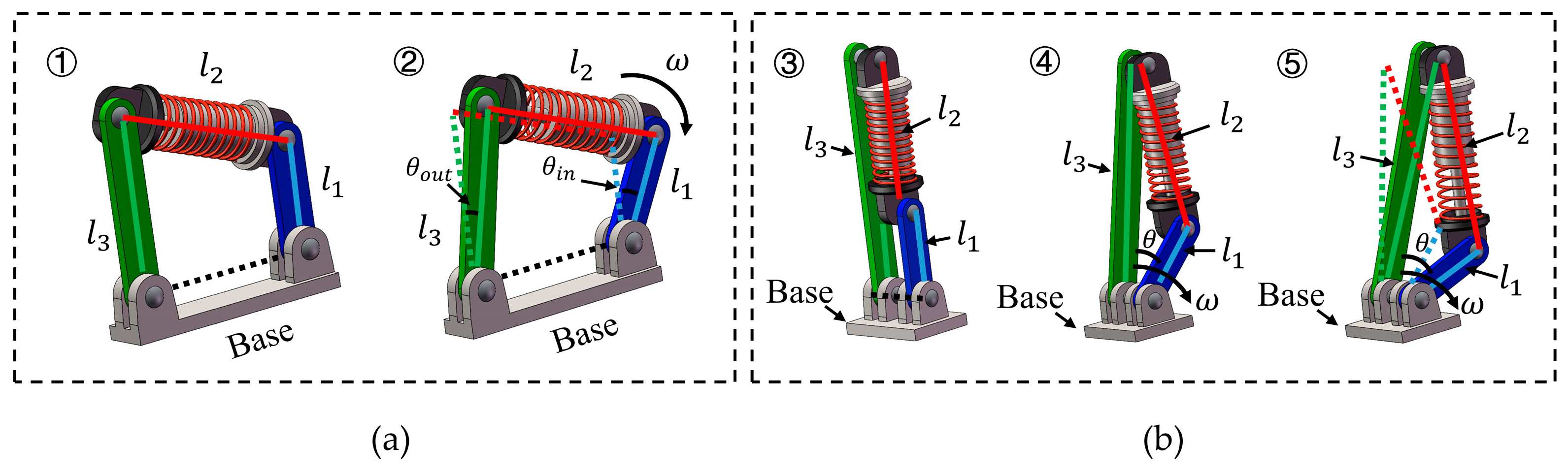
Figure 2.
Construction of adjustable VSM and VSA. (a) Compliant mechanism of nonlinear stiffness behavior with different rod length ratios. (b) Adjustable nonlinear stiffness behavior actuator corresponding to VSM.
Figure 2.
Construction of adjustable VSM and VSA. (a) Compliant mechanism of nonlinear stiffness behavior with different rod length ratios. (b) Adjustable nonlinear stiffness behavior actuator corresponding to VSM.
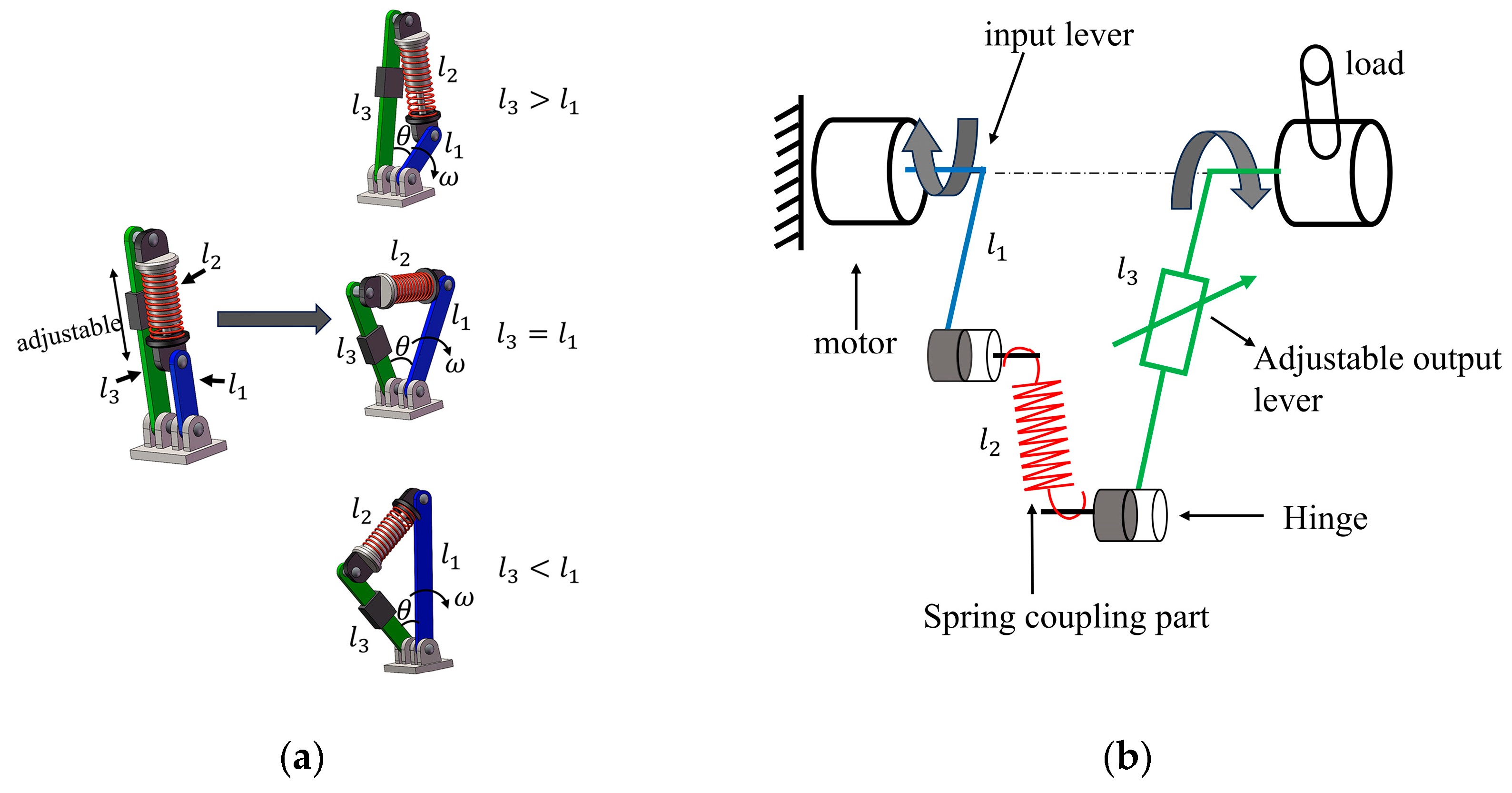
Figure 3.
(a) Influence of deflection angle
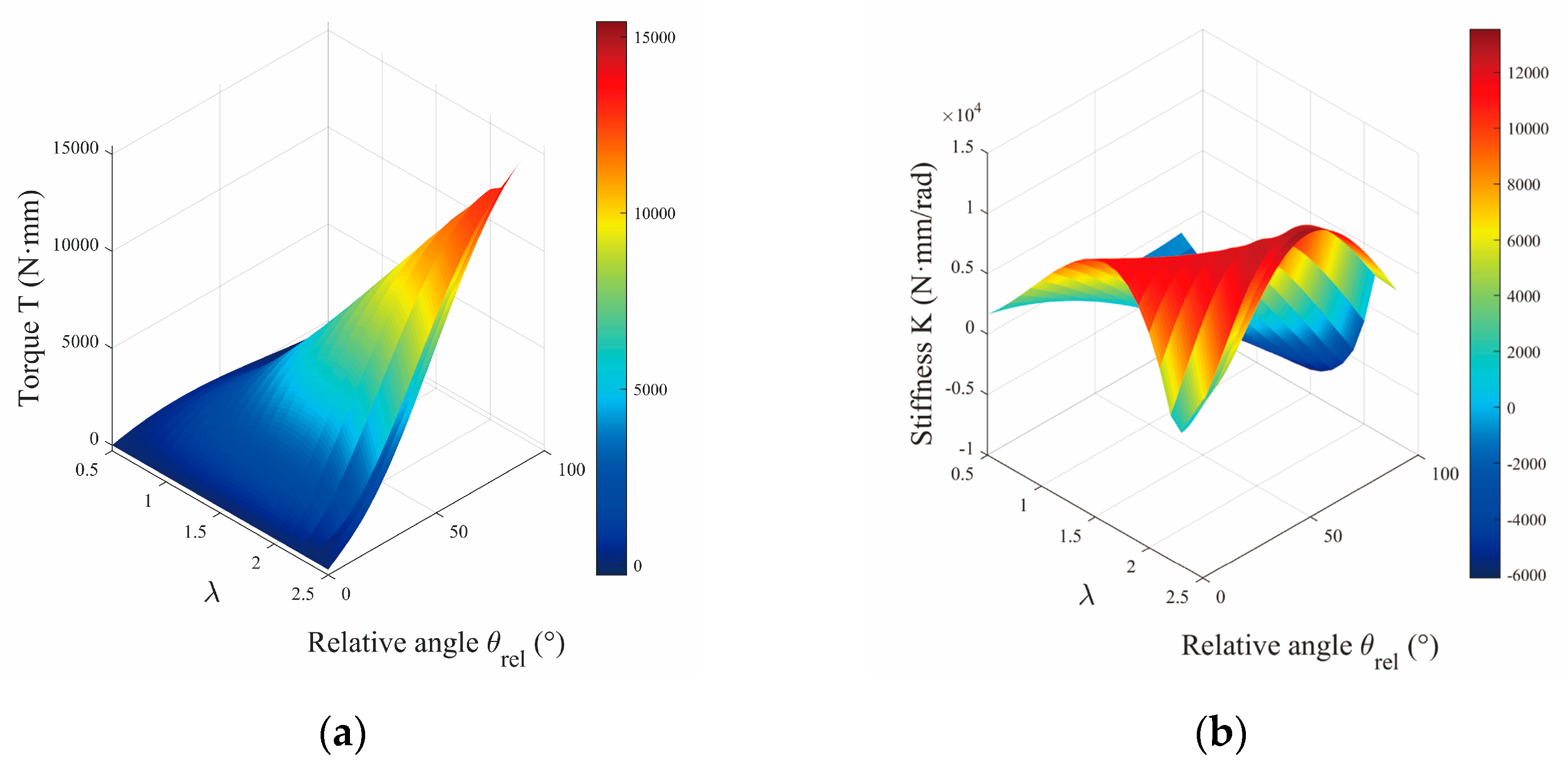
Figure 4.
(a) Influence of deflection angle
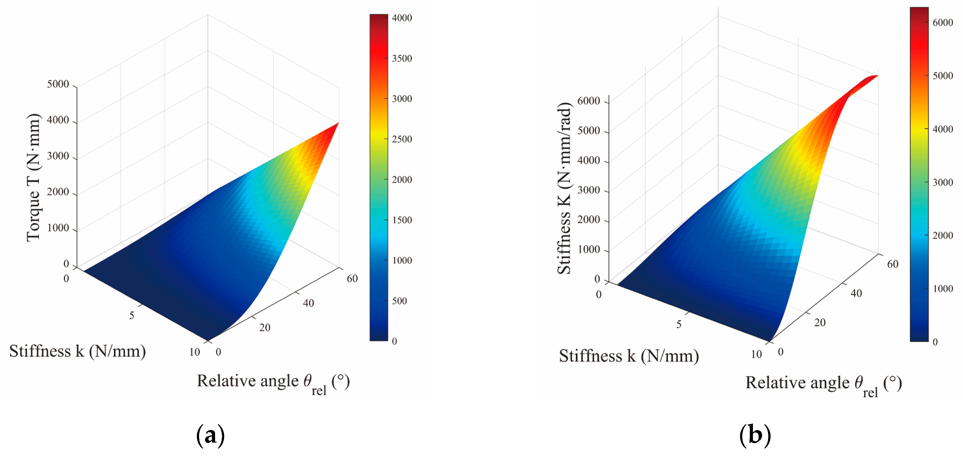
Figure 5.
(a) Initial state diagram of the proposed VSM under different rod length ratios , and (b) state diagram of VSM driven by different deflections when and .
Figure 5.
(a) Initial state diagram of the proposed VSM under different rod length ratios , and (b) state diagram of VSM driven by different deflections when and .
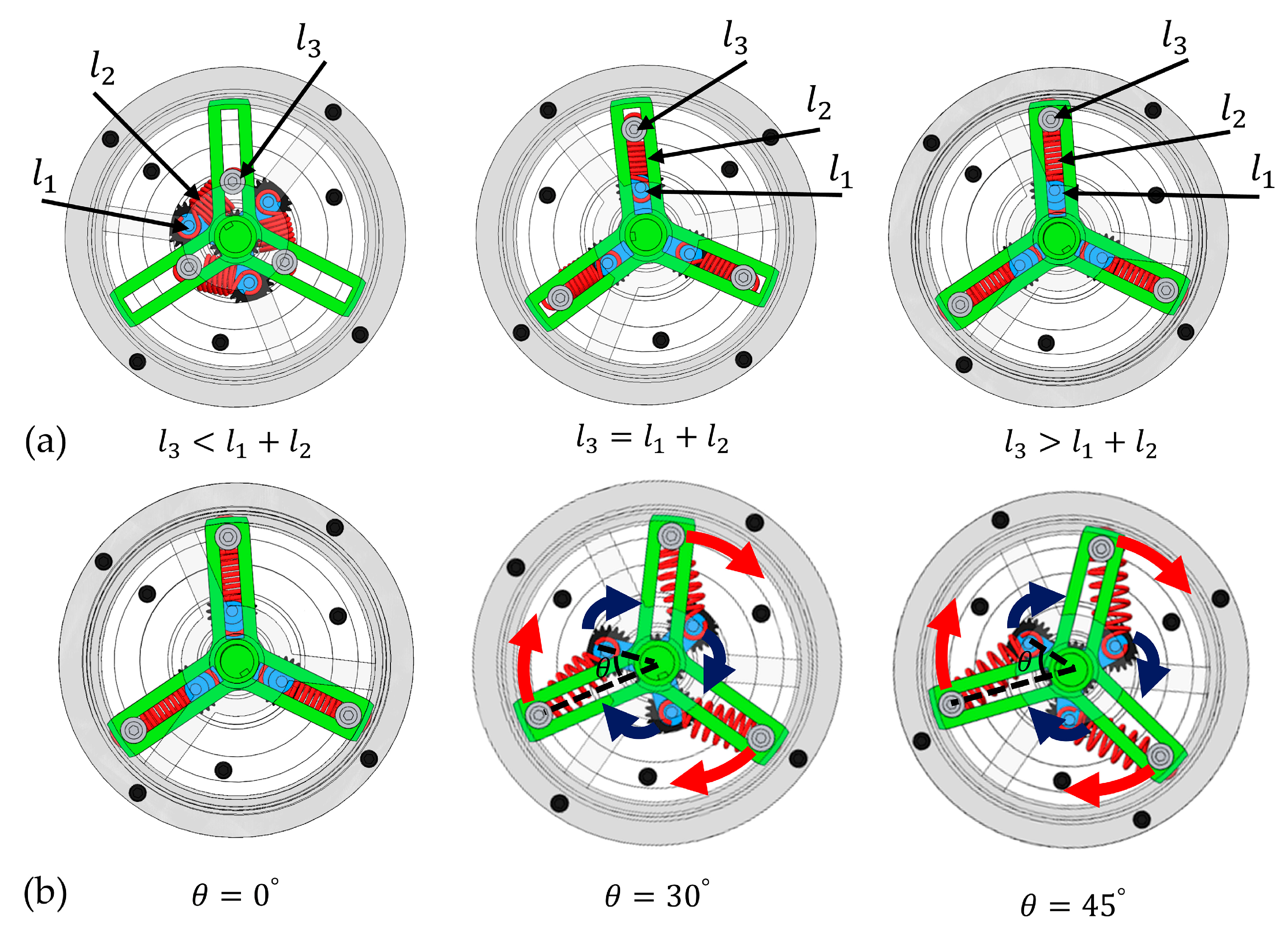
Figure 6.
CAD model of the compliant actuator designed with the VSM.
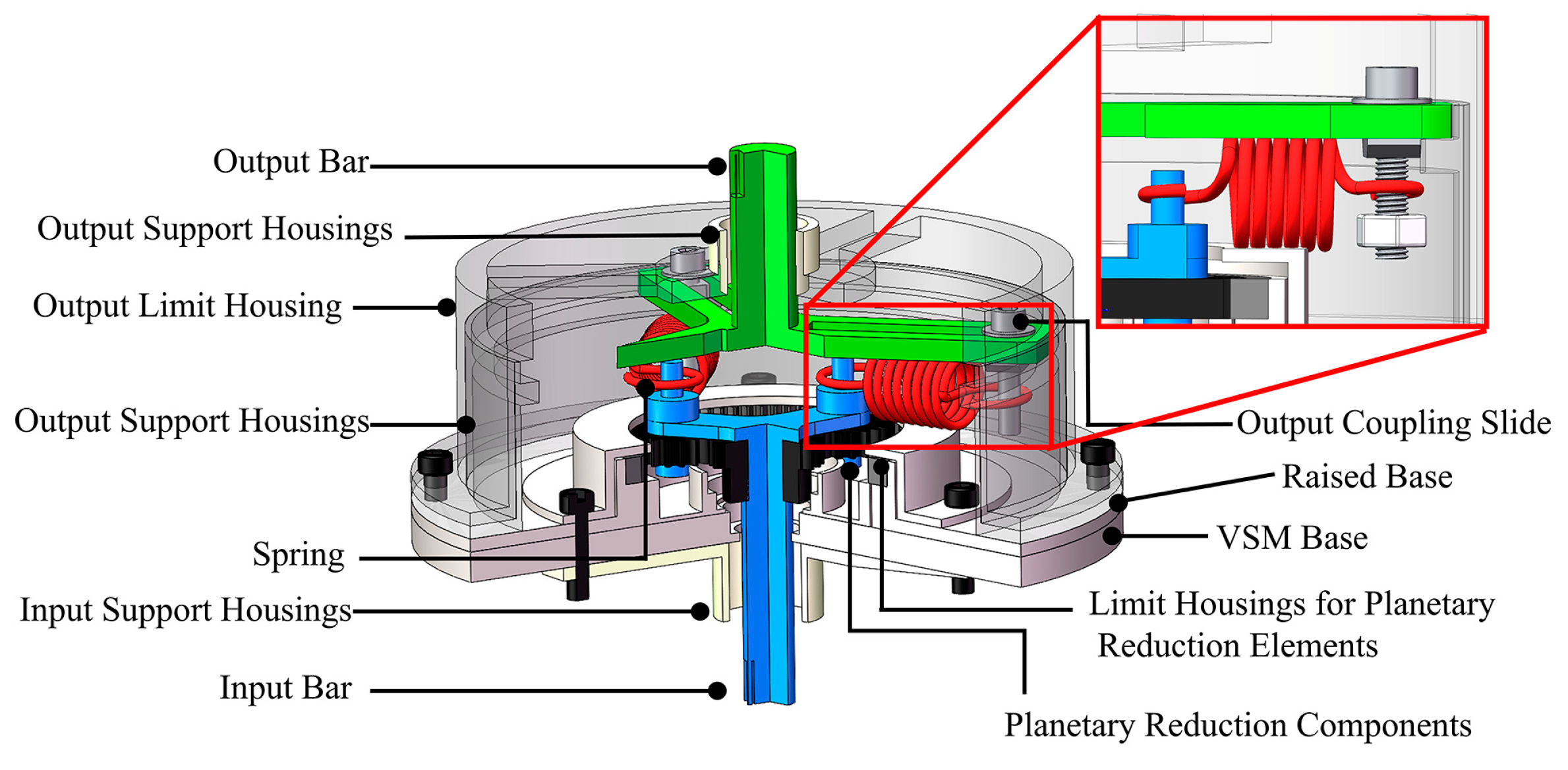
Figure 7.
VSM test rig constructed with (1) power supply unit, (2) motor-gearbox, (3) VSM, (4) torque sensor, (5) encoder, (6) load cell (7) PC.
Figure 7.
VSM test rig constructed with (1) power supply unit, (2) motor-gearbox, (3) VSM, (4) torque sensor, (5) encoder, (6) load cell (7) PC.
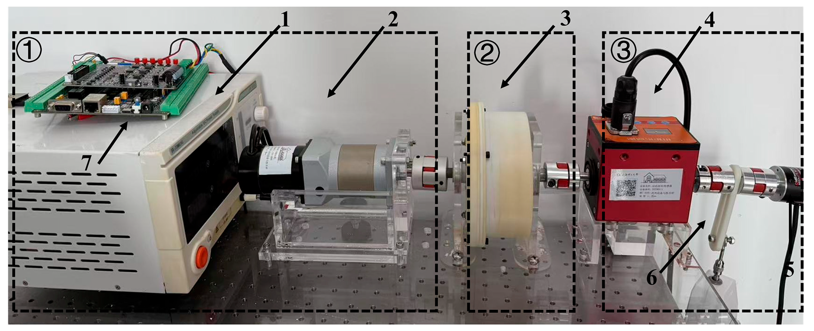
Figure 8.
(a)Quasi-static torque–deflection characteristics with and = 2.5N/mm. Solid curves denote theoretical predictions and symbols denote measurements for = {0.7,1.0,1.5,2.3,2.5}. Larger yields a steeper torque–angle slope. (b)Same protocol with a stiffer spring (= 4.3N/mm). Relative to (a), both the torque level and the local slope increase across all , reflecting the effect of spring stiffness; agreement between theory and experiment is maintained.
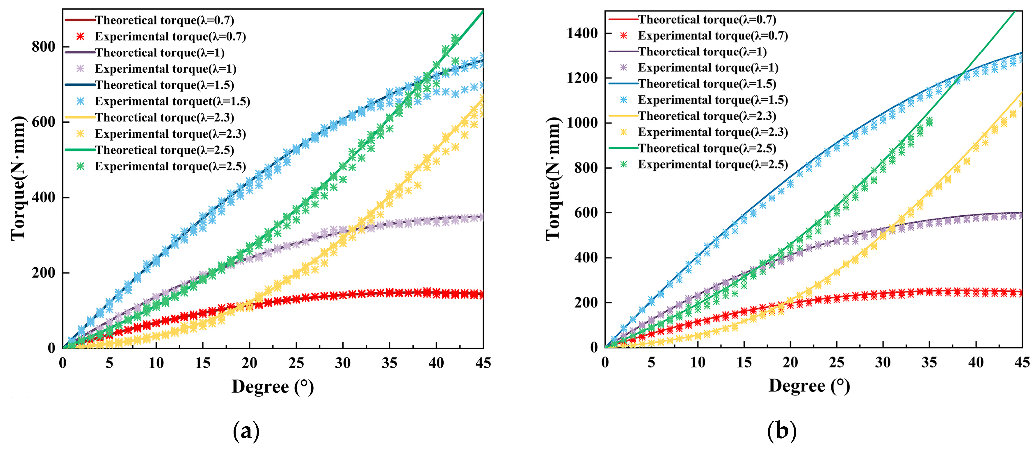
Figure 9.
(a)Comparison of theoretical stiffness and experimentally characterized stiffness as a function of deflection angle , corresponding to different rod length ratios , where and = 2.5N/mm, with the points representing the experimental average results and the solid line representing the theoretical stiffness. (b)Same protocol with a stiffer spring (= 4.3 N/mm). Relative to (a), both the stiffness level and its variation with increase across all , while agreement between theory and experiment is preserved.

Figure 10.
(a) Pendulum swing experiment corresponds to = 2.3 and = 2.5, each executed for at least six oscillation cycles between to to with and = 2.5N/mm. (b)With a stiffer spring ( and = 4.3N/mm). The motion profile is identical to (a) (6 cycles between and ). The torque–angle curves exhibit a steeper slope, and the = 2.5 setting yields consistently higher torque than = 2.3.
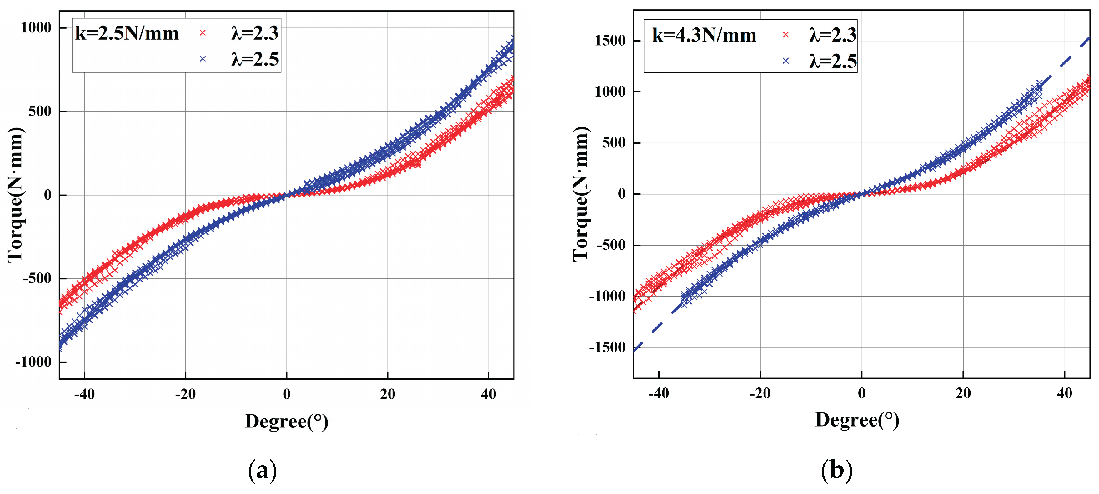

Table 1.
Key Dynamic Parameters of the Proposed VSA.
| Parmeter | Value | Unit |
| Size(length×width×height) | mm | |
| Weight | 0.8 | kg |
| Number of spring () | Up to 3 | pair |
| Stiffness of spring () | 2.5/4.3 | N/mm |
| Length of spring () | 30 | mm |
| Length of input rod () | 24 | mm |
| Length of output rod () | 12 to 60 | mm |
Table 2.
Spring Parameters.
| Design parameters | Spring selected | ||||||||
| Spring | Type | Stiffness | Initial Tension | Permissible load duration | Model | ||||
| Spring 1 | Linear spring | 2.5N/mm | 5.1 N | mm | MiSuMiC-AWT5-25 | ||||
| Spring 2 | Linear spring | 4.3N/mm | 9.81N | kg | MiSuMiC-AWT10-3 | ||||
Disclaimer/Publisher’s Note: The statements, opinions and data contained in all publications are solely those of the individual author(s) and contributor(s) and not of MDPI and/or the editor(s). MDPI and/or the editor(s) disclaim responsibility for any injury to people or property resulting from any ideas, methods, instructions or products referred to in the content. |
© 2025 by the authors. Licensee MDPI, Basel, Switzerland. This article is an open access article distributed under the terms and conditions of the Creative Commons Attribution (CC BY) license (http://creativecommons.org/licenses/by/4.0/).
Copyright: This open access article is published under a Creative Commons CC BY 4.0 license, which permit the free download, distribution, and reuse, provided that the author and preprint are cited in any reuse.


