
Submitted:
25 July 2025
Posted:
29 July 2025
You are already at the latest version
Abstract
: The need to improve gait emulation in patients with transfemoral amputation has led to the development of customized prosthetic mechanisms. This study focuses on the design and validation of an external knee joint prosthesis mechanism, based on the trajectory of the Instantaneous Center of Rotation (ICR) of a healthy knee. The goal is to design a mechanism that closely follows the evolution of the ICR path, improving stability and reducing the user's muscle effort. An exploratory methodology was applied, using computer-aided design (CAD), kinematic simulations, and rapid prototyping with 3D printing. Several four-bar and six-bar mechanism configurations were evaluated by determining their ICR trajectories and comparing them to a reference model obtained in the lab from a specific patient, using MATLAB and Fréchet distance as the error metric. The results showed that the optimized four-bar mechanism, with the addition of gears, achieved the highest accuracy in matching the ICR trajectory, with a minimum error of 5 mm. Functional tests confirmed the effectiveness of the design in terms of stability and voluntary control during walking. It is concluded that optimizing the mechanism design based on the ICR significantly improves functionality and supports its clinical implementation and impact on users’ quality of life.
Keywords:
Instantaneous Center of Rotation
; knee prosthesis
; gait emulation
; four-bar mechanism
; rapid prototyping
1. Introduction
The loss of a lower limb, particularly at the transfemoral level, presents a major challenge for patients’ mobility and quality of life [1]. The biomechanics of the knee is essential for stable and efficient walking, and replacing its function with an external prosthesis remains both a technological and clinical challenge [2,3]. Currently, most commercially available knee prostheses have limitations in replicating natural gait, as they rely on standard mechanisms that do not adapt to the anatomical and kinematic differences of each user [4,5,6,7].
The use of standard devices such as knee prostheses, exoskeletons, and rehabilitation systems introduces additional challenges when they are not accurately aligned with the individual biomechanics of each patient [8]. Most of these devices are designed using generic measurements, forcing users to adapt their walking patterns and muscle effort to the mechanics imposed by the system, rather than having the device adapt to their needs [8,9,10,11,12,13]. This lack of personalization can lead to postural compensations, excessive muscle fatigue, instability, and a higher risk of secondary injuries to the spine, hip, and residual limb [8,14]. Furthermore, the mismatch between the natural knee kinematics and the motion path of standard prosthetic mechanisms can result in asymmetric gait patterns, reducing energy efficiency during walking and diminishing overall comfort for the user [15].
In an ideal approach, devices should be designed to match the user’s biomechanical structure, optimizing gait kinematics and reducing the effort required for adaptation. This would improve mobility, stability, and overall quality of life, while minimizing the mechanical compensations that often result from using standard technologies.
Designing mechanisms based on the Instantaneous Center of Rotation (ICR) has proven to be a promising strategy to improve the functionality of knee prostheses, as it allows for more natural movement and reduces the patient’s muscular effort [8,16,17,18]. However, accurately replicating the ICR remains a challenge due to limitations in current kinematic models and the complexity of adjusting the structural parameters of the mechanism [19].
Rapid prototyping using 3D printing has emerged as a key tool in the optimization of medical devices, especially in the design of prostheses, exoskeletons, and rehabilitation systems [20]. 3D printing makes it possible to manufacture highly customized components that match each user’s morphology and biomechanics, overcoming the limitations of standard devices [4,21]. This technology enables quick iterations between different designs, testing of structural and functional variations, and optimization of the mechanism’s kinematics before final production. It not only speeds up the development process but also reduces costs and improves the accuracy of natural movement emulation [8,17]. In the case of knee prostheses, rapid prototyping allows for evaluating and adjusting the ICR trajectory, ensuring that the mechanism adapts to the user’s gait rather than imposing artificial mechanics that compromise mobility [19].
The combination of computer modeling, simulations, and additive manufacturing makes it easier to create innovative solutions that improve the integration between the user and the device, promoting greater functionality, comfort, and energy efficiency during walking.
This study aims to develop and optimize a knee prosthetic mechanism based on the trajectory of the ICR, using a personalized design approach through computer modeling and rapid prototyping. An optimized four-bar mechanism with gears is proposed to improve stability and alignment with the natural kinematics of the human knee.
The results show that the designed mechanism achieves a significant reduction in error when replicating the ICR, improving gait efficiency and user stability. It is concluded that customizing prosthesis design based on the ICR represents a key advancement in developing more functional assistive devices, with the potential to improve the quality of life for patients with transfemoral amputation.
2. Materials and Methods
2.1. Diseño del Estudio
This study an experimental and qualitative approach for the design, prototyping, and validation of a knee prosthesis mechanism base don the ICR. And explorotory investigation using the trial-and-error method was applied, enablinng iterative adjustments to optimize the desing. The proceduce is structured into four main phases.
Figure 1.
Structure of the study.
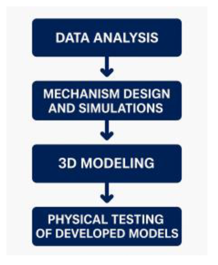
2.1.1. Preliminary Data Analysis
In the laboratory gait trial involving a patient with no lower limb pathology, walking motion is recorded on a treadmill for at least eight continues gait cycles. The data are then processed to obtain the ICR of the knee joint in the sagittal plane, as illustrated in Figure 2. Additionally, the mean of the data is calculated to identify the behavioral trend of the trajectories, allowing for the selection of a reference curve for the present study.
Cycles 6, 7 and 8 were selected due to the continuity of their trajectories. After analyzing their behavior, the trajectory of cycle 6 was chosen as shown in Figure 2, because it best matched the overall data trend and closely resembled the characteristic “J” shape of the estimated ICR trajectory.
Out of 70 functions evaluated, the one that provided the best fit with the lowest standard error was the Rational Regression Model, with a standard error of 2.2367. This function, expressed in Eq. (1), includes the following constants:
a = 2.6863
b = -1.1046
c= -2.8495
r= 3.1302
y = a + b*r ^x + c*x
Once the motion coordinates were obtained, the trajectory was projected in CAD software by placing dimensioned points corresponding to the coordinates of the target curve derived from the mathematical model. Additionally, angle values were indicated as a reference for the knee joint flexion angle, as detailed in Figure 3.
2.1.2. Mechanism Design: CAD Modeling and Computational Simulations
Four-bar and six-bar mechanisms are among the most used. The four-bar mechanism is favored for its ease in applying the trial-and-error method when modifying link dimensions. In contrast, the six-bar mechanism allows for a more accurate adaptation of motion to the required trajectory.
To properly align the reference curve of the Instantaneous Center of Rotation (ICR) with the links of the mechanism to be designed, it is essential to define a set of quantitative design parameters.
2.1.3. 3D Modeling
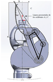
The links of the four-bar mechanism are shown alongside the reference ICR curve, positioned according to the specifications provided in Table 1 and Table 2. Link B is fixed, and the projection of links A and C generates the Instantaneous Center of Rotation (ICR) during gait.
The ICR origin is positioned approximately 100 mm from the anatomical center of the knee and 6 mm posterior to the leg’s reference axis. To verify stability, load lines corresponding to heel contact and toe-off are drawn. As shown in Figure 3, the ICR origin lies within the stability zone, thereby meeting the specifications of a voluntary control mechanism.
Once the mechanism is positioned and aligned with the leg, the iteration process continues with different link sizes until the desired trajectory is closely matched. The three most relevant models are presented below.
Model 1
The dimensions of the four links were adjusted until a configuration was achieved that generates a trajectory like the target ICR curve. Additionally, the angle between link B and the horizontal axis was modified. The corresponding dimensions are provided in Table 3 and Figure 4.
The ICR trajectory in Model 1 shows a certain similarity to the behavior of the target trajectory, although a greater overall length is observed. Additionally, when analyzing the correlation between the angle indicated in the target ICR curve and the angle generated between the coupler and the anatomical axis of the leg, a 50-degree difference in flexion is identified.
Model 2
To adjust the generated ICR curve trajectory, several modifications are made to the four-bar mechanism regarding the position of the ICR origin and the stability zone, as shown in Figure 5.
To ensure that the mechanism remains within the stability zone and that the curve aligns with the reference size, the vertical distance between the anatomical center of the knee and the ICR origin is reduced to 75.424 mm, while the horizontal distance is maintained at 6 mm relative to the anatomical axis, as shown in Figure 5. Another important detail is the position of link B, located 35.5 mm from the anatomical axis of the leg and at an angle of 34° with respect to the horizontal line, as illustrated in Figure 6. Additionally, the model dimensions are detailed in Table 4.
Model 3
This model represents an optimized version that maintains both the link dimensions and the angles between them, differing by the incorporation of gears with a transmission ratio of Rt = 0.93 and an improved aesthetic design.
A gear train is implemented, with one gear per shaft, configured so that the direction of rotation corresponds to the flexion movement of the leg. Additionally, an idler gear is included, which does not affect the transmission ratio Rt. The gear specifications are detailed in Table 5 and Table 6 and Figure 7
Mechanical motion constraints were added to Model 3 to prevent hyperextension in extension, as well as to limit flexion, with a maximum flexion angle of 60 degrees, as shown in Figure 8
This model also includes a flexible and replaceable component, designed to fit into the coupler, which helps absorb impact during the stance phase of gait, as shown in Figure 8 (blue-colored element).
2.1.4. Functionality Tests
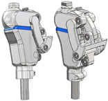
For the development of the prototypes and the functionality tests, 3D printing using fused deposition modeling (FDM) with PET-G material was employed for most components, using 100% infill during slicing. Additionally, standard elements such as 5 mm diameter bearings, shafts, and retaining rings were selected to complete the assembly. Figure 9 shows the prototypes ready to be tested with the same subject from whom the ICR trajectory was obtained.
Functionality tests were conducted on Models 1 and 3 presented in this study. For this purpose, an adapted socket was used to allow testing with the same subject from whom the target ICR was obtained. Controlled trials were carried out at the facilities of Fundación Prótesis Imbabura, with the support of specialized physiotherapy personnel.
Model 1, shown in Figure 9a, enables functional walking, although not fully efficient. High energy expenditure was observed during gait, and certain limitations were identified. Due to the absence of a compression spring, greater effort is required to return the foot after the swing phase. Additionally, the coupler, located 66 mm posterior to the leg’s load line, compromises the user’s balance.
Model 3, shown in Figure 9b, successfully emulates the subject’s natural gait without limitations, restrictions, or difficulties. Its mechanism enables safe walking, maintaining balance and voluntary control of movement. There is no gear interference, and the compression spring enhances comfort by automatically returning the foot after the swing phase. Additionally, the flexible damping component reduces load and impact on the residual limb during the return to the stance phase, improving movement efficiency and smoothness.
To verify the ICR trajectories of the main models, it can be observed that Model 3 presents the greatest similarity to the reference curve, as shown in Figure 10.
One way to measure the similarity between trajectories is by using the Discrete Fréchet Distance, which allows us to quantify it based on the values shown in Table 7. Model 5 stands out with a value of 5.33 mm, demonstrating that it is an acceptable approximation, as confirmed by the physical tests.
3. Knee Joint Flexion During Gait
The flexion movement of the leg during gait is vital for maintaining cadence, balance, and proper posture, and it also serves to evaluate Model 3. As shown in Figure 11, the flexion angles during the gait cycle of Model 3 are obtained, and as illustrated in Figure 12, they resemble the movement cycles of a healthy leg, demonstrating proper functionality.
4. Discussion
This study focused on the design and optimization of a mechanism for an external knee prosthesis based on the trajectory of the Instantaneous Center of Rotation (ICR), aiming to improve the emulation of human gait in transfemoral amputee patients. The results show that the optimized four-bar mechanism with gears provides the best approximation to the ICR trajectory, with a minimal error of 5 mm compared to the reference model.
The main contribution of this work lies in the application of a personalized design approach based on the user’s individual biomechanics. In contrast to standard commercial prostheses, which impose a predefined kinematic pattern that can lead to postural compensations and increased muscular effort, the developed mechanism enables a more accurate adaptation to the user’s gait. This results in a significant improvement in stability and a reduction in the load on the residual limb—both critical factors for user comfort and efficiency.
From a methodological standpoint, the integration of computational tools such as MATLAB and CAD, along with the use of 3D printing for rapid prototyping, enabled an iterative optimization process in which different four-bar and six-bar mechanism configurations were compared. The four-bar mechanism with gears demonstrated the best balance between trajectory accuracy and structural stability. Additionally, the incorporation of a compression spring and a flexible damping component enhanced user comfort and reduced impact during the stance phase of gait.
Compared to previous studies on knee prosthesis design based on the ICR, this research achieved a lower Fréchet distance in the emulation of the ICR trajectory, indicating greater fidelity in reproducing natural knee movement. Likewise, the functional results obtained from experimental testing with the user validated the effectiveness of the design, demonstrating a more natural gait and reduced muscular effort.
However, there are certain limitations in this study that should be considered in future research. First, the mechanism was validated using a single test subject, so it would be necessary to expand the sample to assess its applicability to a more diverse population. Additionally, the evaluation focused on the kinematic analysis of movement; therefore, future studies could incorporate measurements of energy consumption and muscle fatigue for a more comprehensive assessment of prosthesis performance.
5. Conclusions
In conclusion, this study demonstrates that optimizing knee prosthesis design based on the ICR is a viable strategy to improve the functionality and comfort of prosthetic devices. The implementation of advanced modeling and prototyping technologies enables more precise customization, offering significant benefits for users’ quality of life. It is recommended to continue developing new iterations of the mechanism, incorporating broader clinical trials to validate its impact across different patient profiles.
Abbreviations
The following abbreviations are used in this manuscript:
| ICR | Instant Center of Rotation |
| CAD | Computer Aided Design |
References
- Dadkhan B, Valizadeh S, Mohammadi E, Hasssankhani H. Psychosocial adjustment to Lower-limb amputation. HealthMED [Internet]. 2013 [cited 2025 Feb 27];7. Available from: https://www.researchgate.net/profile/Ivan-Merdzhanov-2/publication/272419418_An_electronic_learning_tool_to_improve_language_related_communication_skills_in_healthcare_settings/links/54e3d2cd0cf282dbed6daefb/An-electronic-learning-tool-to-improve-language-related-communication-skills-in-healthcare-settings.pdf#page=159.
- Andriacchi TP, Stanwyck TS, Galante JO. Knee Biomechanics and Total Knee Replacement.
- Andriacchi TP, Stanwyck TS, Galante JO. Knee Biomechanics and Total Knee Replacement.
- Grodzka K, Sajewicz E, Dziemianowicz Marcin. Chapter 5 Kinematic analysis of instantaneous centre of rotation of prosthetic knee mechanisms. 2023 Jan 5; Available from: https://www.researchgate.net/publication/366878422.
- Barbu, DM. A total knee prosthesis CAD design. 2017 E-Health Bioeng Conf EHB 2017. 2017;511–4.
- Sánchez J, Hernández RJ, Torres JE. The mechanical design of a transfemoral prosthesis using computational tools and design methodology. Ing e Investig. 2012;32(3):14–8.
- Andrysek J, Michelini A, Eshraghi A, Kheng S, Heang T, Thor P. Gait Performance of Friction-Based Prosthetic Knee Joint Swing-Phase Controllers in Under-Resourced Settings. Prosthesis. 2022 Mar 15;4(1):125–35. [CrossRef]
- Murabayashi M, Mitani T, Inoue K. Development and Evaluation of a Passive Mechanism for a Transfemoral Prosthetic Knee That Prevents Falls during Running Stance. Prosthesis. 2022;4(2):172–83. [CrossRef]
- Li Z, Han Y, Liu C, Xiu H, Wei G, Ren L. Design_Manufacture_and_Experimental_Validation_of_a_Hydraulic_Semi_Active_Knee_Prosthesis. IEEE Trans NEURAL Syst Rehabil Eng. 2023;31:1394–404.
- Minnoye ALM, Plettenburg DH. Design, fabrication, and preliminary results of a novel below knee prosthesis for snowboarding: A case report. Procedia Eng [Internet]. 2010;2(2):3133–41. Available from. [CrossRef]
- Zhang Y, Cao W, Yu H, Meng Q, Lv J. A four-bar knee joint measurement walking system for prosthesis design. Technol Heal Care. 2021;29(4):823–8. [CrossRef]
- Zhang Y, Wang E, Wang M, Liu S, Ge W. biomimetics Design and Experimental Research of Knee l Joint Prosthesis Based on Gait Acquisition Technology. 2021; Available from. [CrossRef]
- Salas P, Vergara ;, Mary, Provenzano ;, Sebastian. Prótesis de rodilla: Fundamentos teóricos y técnicas computacionales para su diseño Knee Prosthesis: theoretical foundations and computational techniques applied to its design. Vol. 42, Revista Ciencia e Ingeniería. 2021.
- Hagberg K, Brånemark R. Consequences of non-vascular trans-femoral amputation: a survey of quality of life, prosthetic use and problems. Vol. 25, Prosthetics and Orthotics International. 2001.
- Wang, S. Biomechanical Analysis of the Human Knee Joint. J Healthc Eng. 2022;2022.
- Claessens, T. Finding the location of the instantaneous center of rotation using a particle image velocimetry algorithm. Am J Phys. 2017 Mar;85(3):185–92. [CrossRef]
- Sajewicz, E. Chapter 5 Kinematic analysis of instantaneous centre of rotation of prosthetic knee mechanisms. 2023;(January).
- Koo S, Andriacchi TP. The knee joint center of rotation is predominantly on the lateral side during normal walking. J Biomech. 2008;41(6):1269–73. [CrossRef]
- Wang, S. Biomechanical Analysis of the Human Knee Joint. Vol. 2022, Journal of Healthcare Engineering. Hindawi Limited; 2022.
- Ahrendt D, Romero Karam A. Development of a computer-aided engineering–supported process for the manufacturing of customized orthopaedic devices by three-dimensional printing onto textile surfaces. J Eng Fiber Fabr. 2020;15. [CrossRef]
- Alkhatib F, Cabibihan JJ, Mahdi E. Data for benchmarking low-cost, 3D printed prosthetic hands. Data Br [Internet]. 2019;25:104163. Available from. [CrossRef]
Figure 2.
Trajectories of the Instantaneous Center of Rotation of the knee joint in the sagittal plane across gait cycles.
Figure 2.
Trajectories of the Instantaneous Center of Rotation of the knee joint in the sagittal plane across gait cycles.
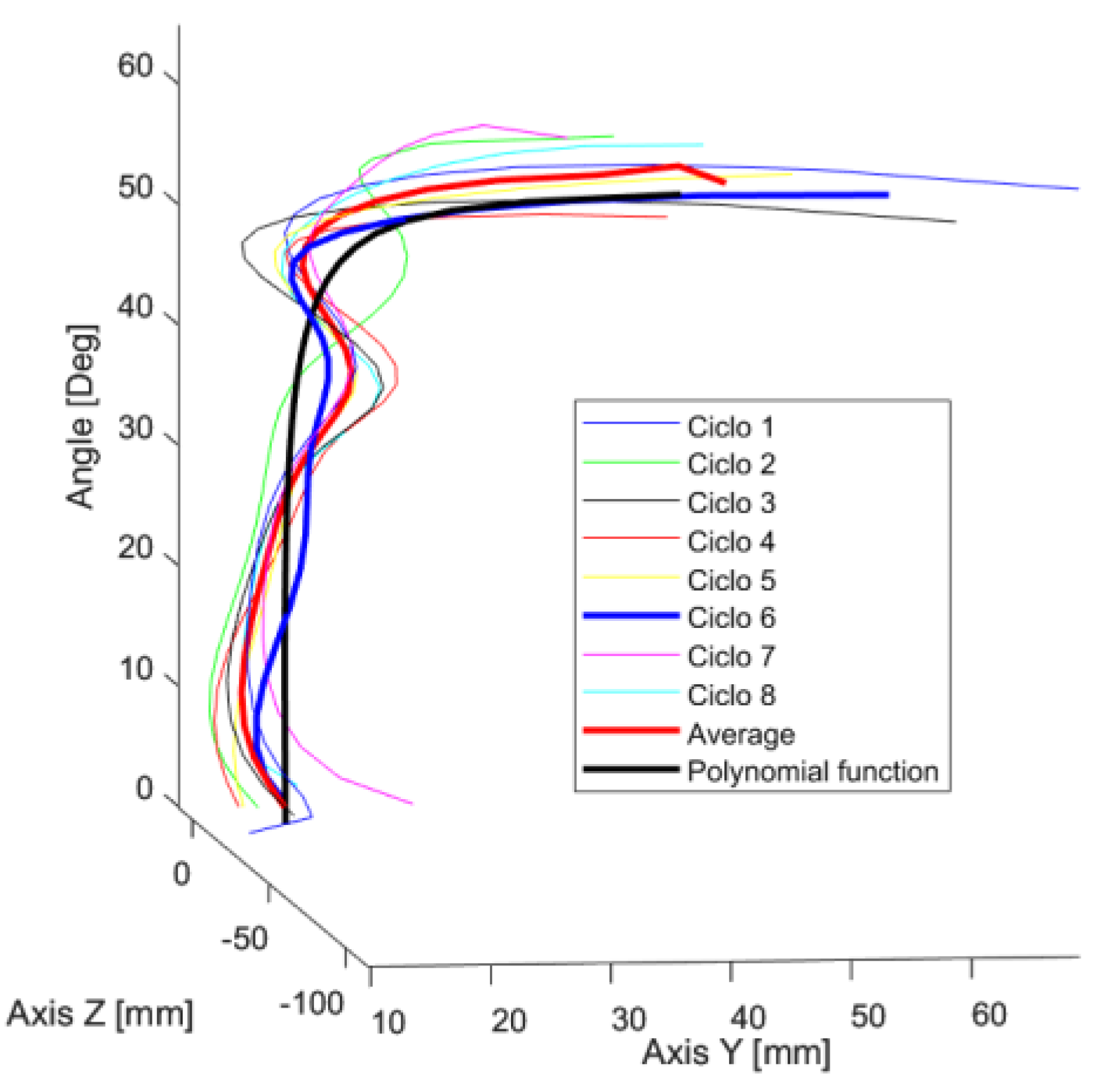
Figure 3.
Positioning of the target ICR curve and the four-bar mechanism: (a) Anatomical placement of the mechanism, (b) Voluntary control zone.
Figure 3.
Positioning of the target ICR curve and the four-bar mechanism: (a) Anatomical placement of the mechanism, (b) Voluntary control zone.
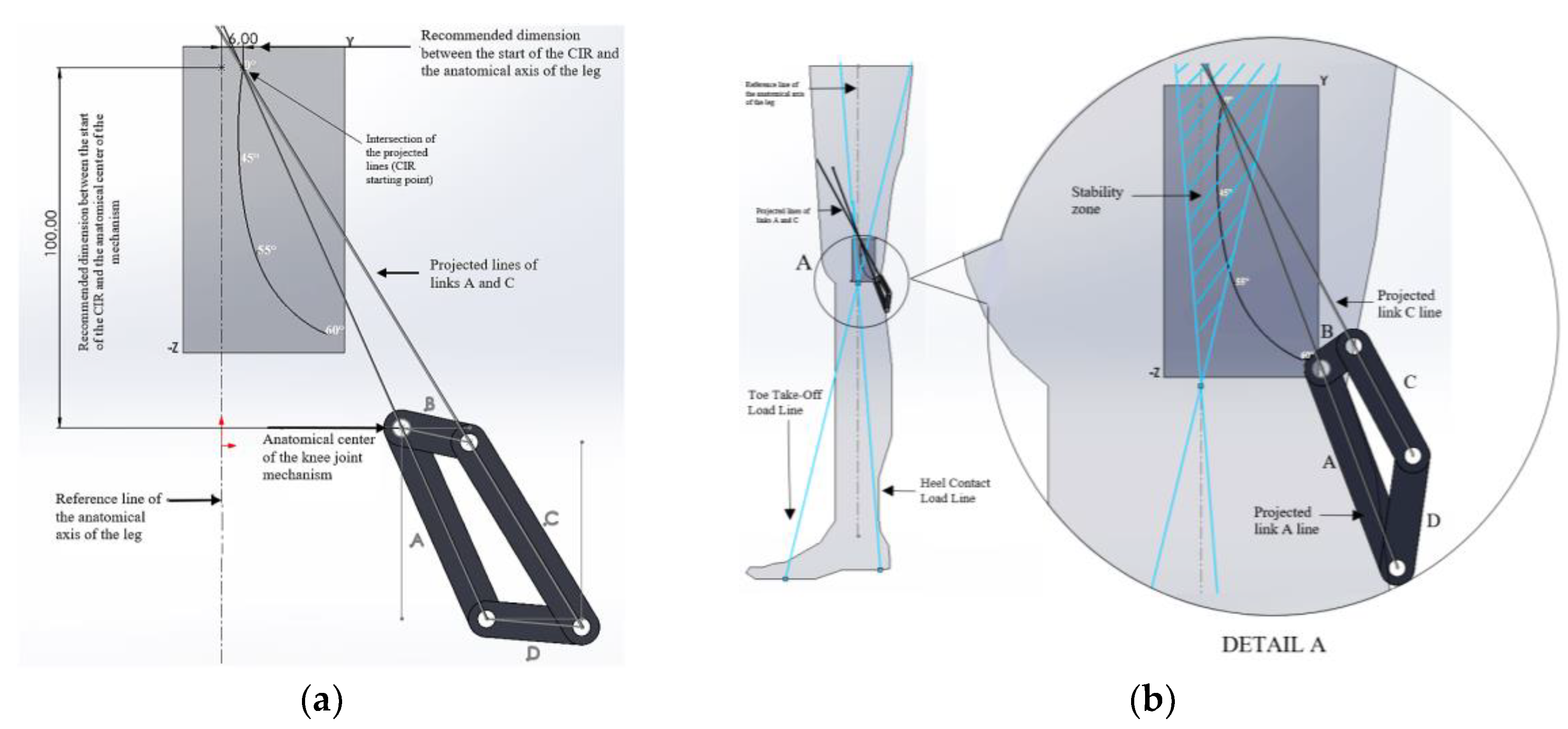
Figure 4.
Link B is positioned as fixed at an angle of 33.2 degrees relative to the horizontal line.
Figure 4.
Link B is positioned as fixed at an angle of 33.2 degrees relative to the horizontal line.
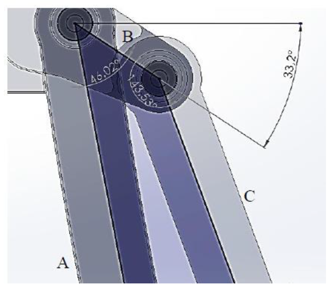
Figure 5.
Mechanism positioning: (a) ICR origin, (b) Voluntary control adjustment.
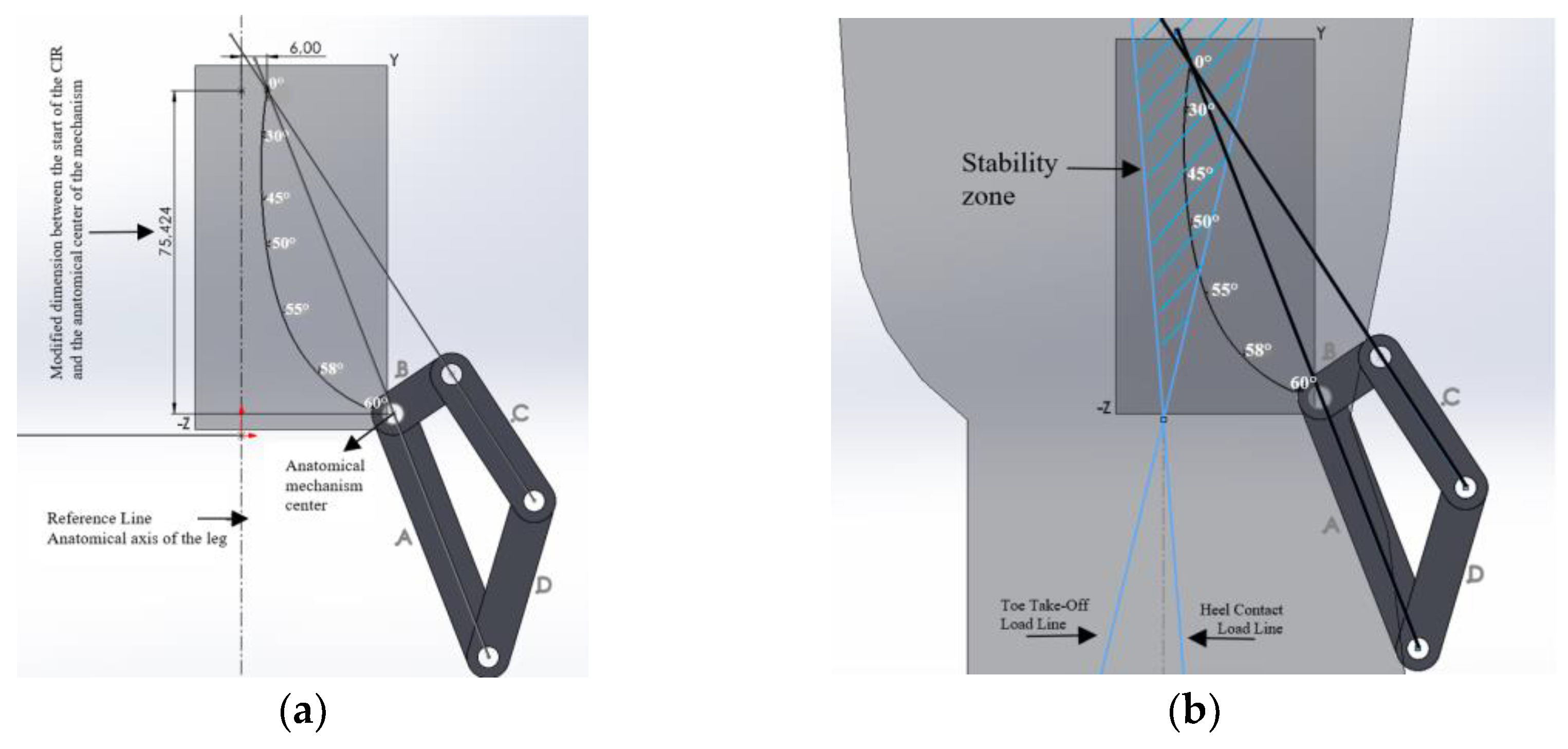
Figure 6.
Position of link B.
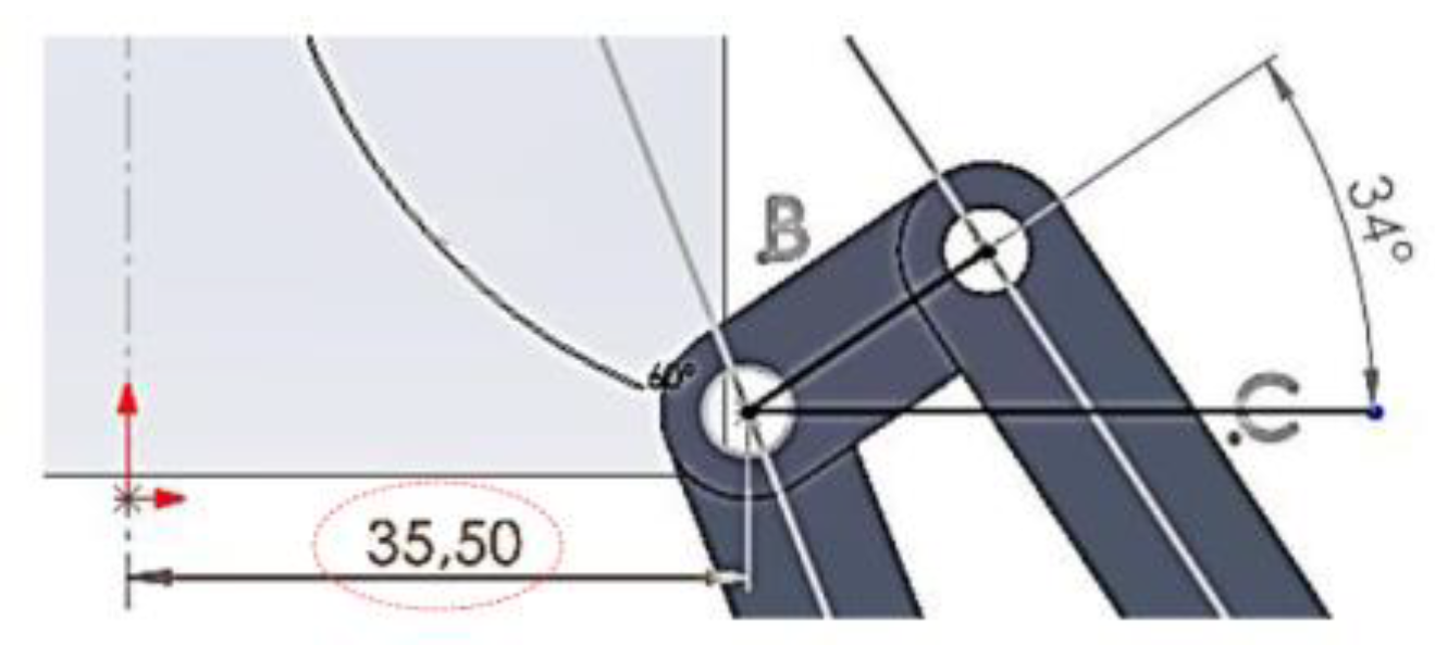
Figure 7.
Shows the position of the gears, the length of the line of action (z), and the physical verification that there is no interference: (a) Gear positioning, (b) Line of action (z).
Figure 7.
Shows the position of the gears, the length of the line of action (z), and the physical verification that there is no interference: (a) Gear positioning, (b) Line of action (z).
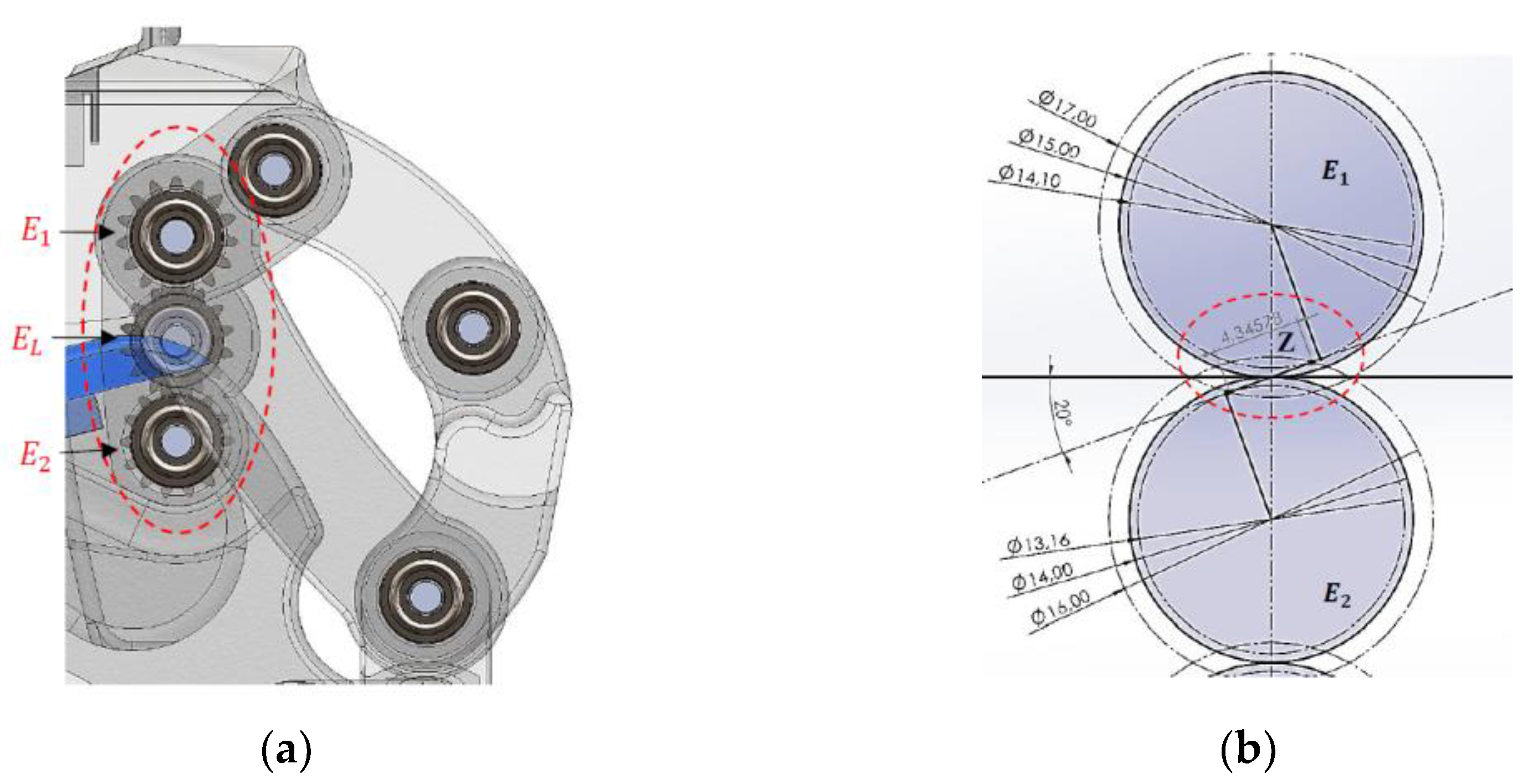
Figure 8.
Motion Constraints, a) Maximum extension, b) Flexion limit.
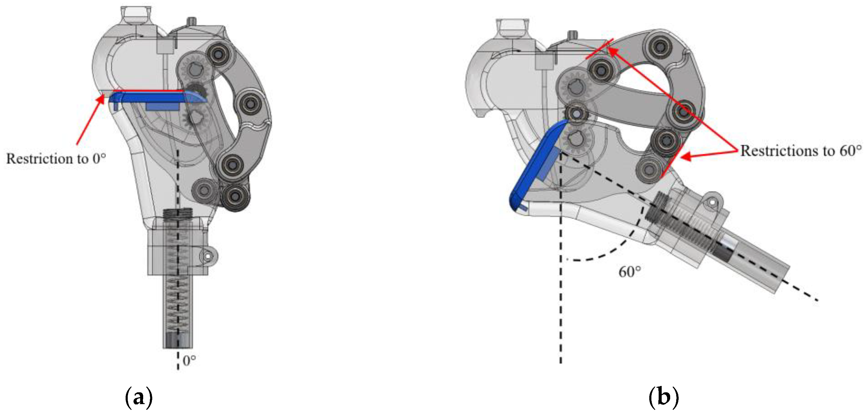
Figure 9.
Functionality, a) Model 1 b) Model 3.
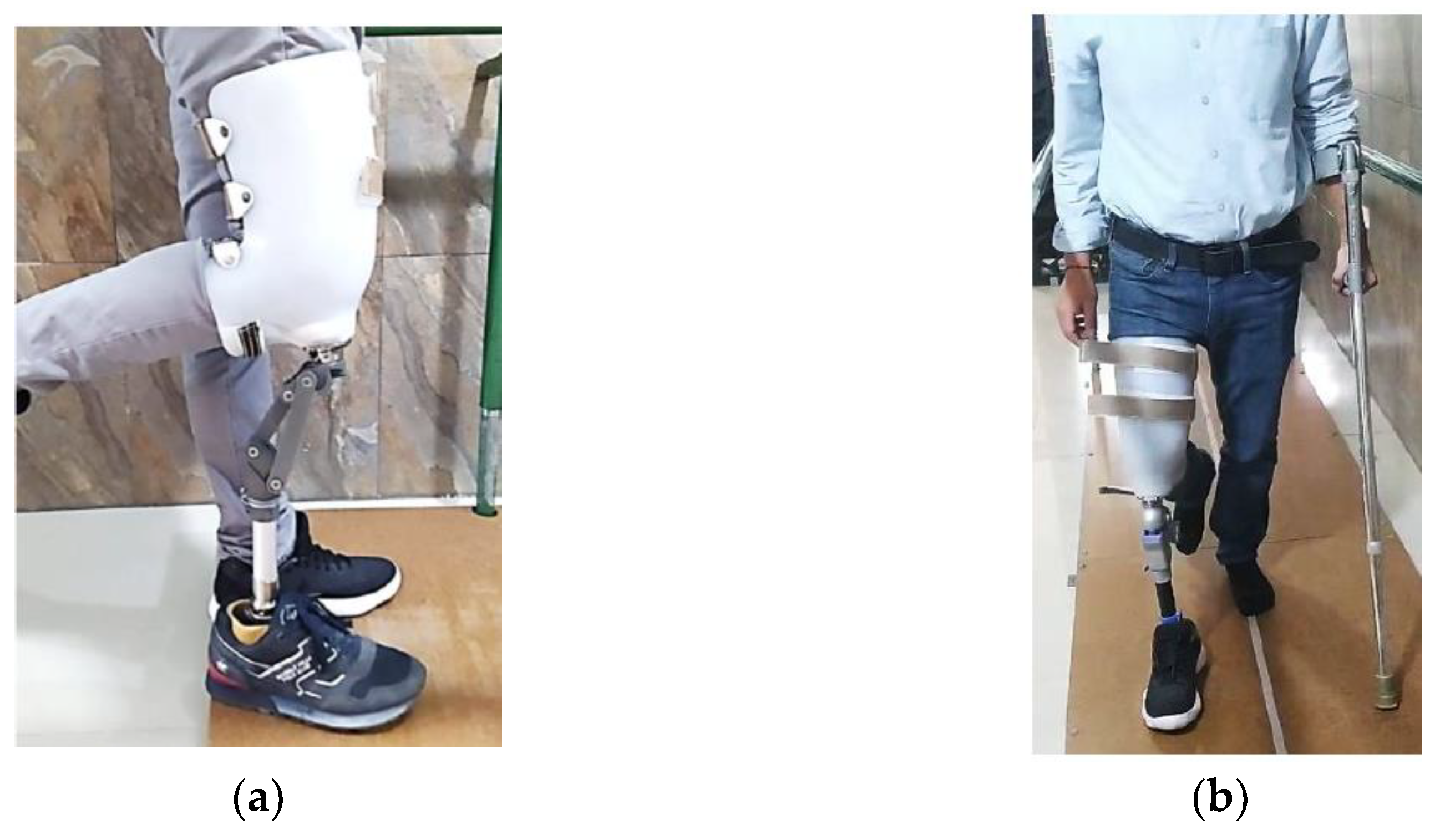
Figure 10.
Displays the ICR trajectories of the three main models, along with the reference curve.
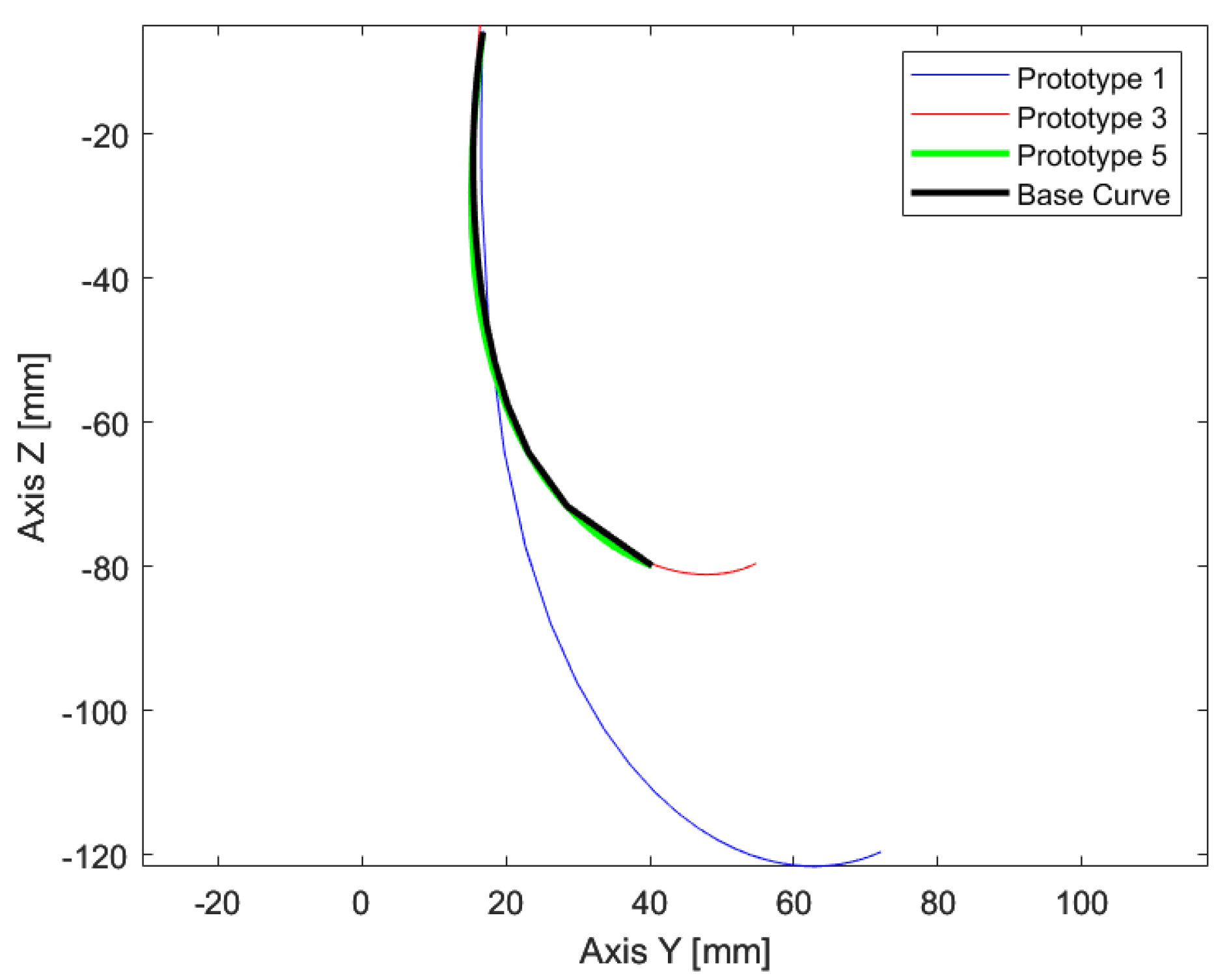
Figure 11.
Gait cycle during Model 3 walking: (a) Initial contact 0%, (b) Mid-stance 10%, (c) Mid-stance 20%, (d) Mid-stance 30%, (e) Terminal stance 40%, (f) Terminal stance 50%, (g) Pre-swing 60%, (h) Initial swing 70%, (i) Mid-swing 80%, (j) Terminal swing 90%, (k) Terminal swing 100%.
Figure 11.
Gait cycle during Model 3 walking: (a) Initial contact 0%, (b) Mid-stance 10%, (c) Mid-stance 20%, (d) Mid-stance 30%, (e) Terminal stance 40%, (f) Terminal stance 50%, (g) Pre-swing 60%, (h) Initial swing 70%, (i) Mid-swing 80%, (j) Terminal swing 90%, (k) Terminal swing 100%.
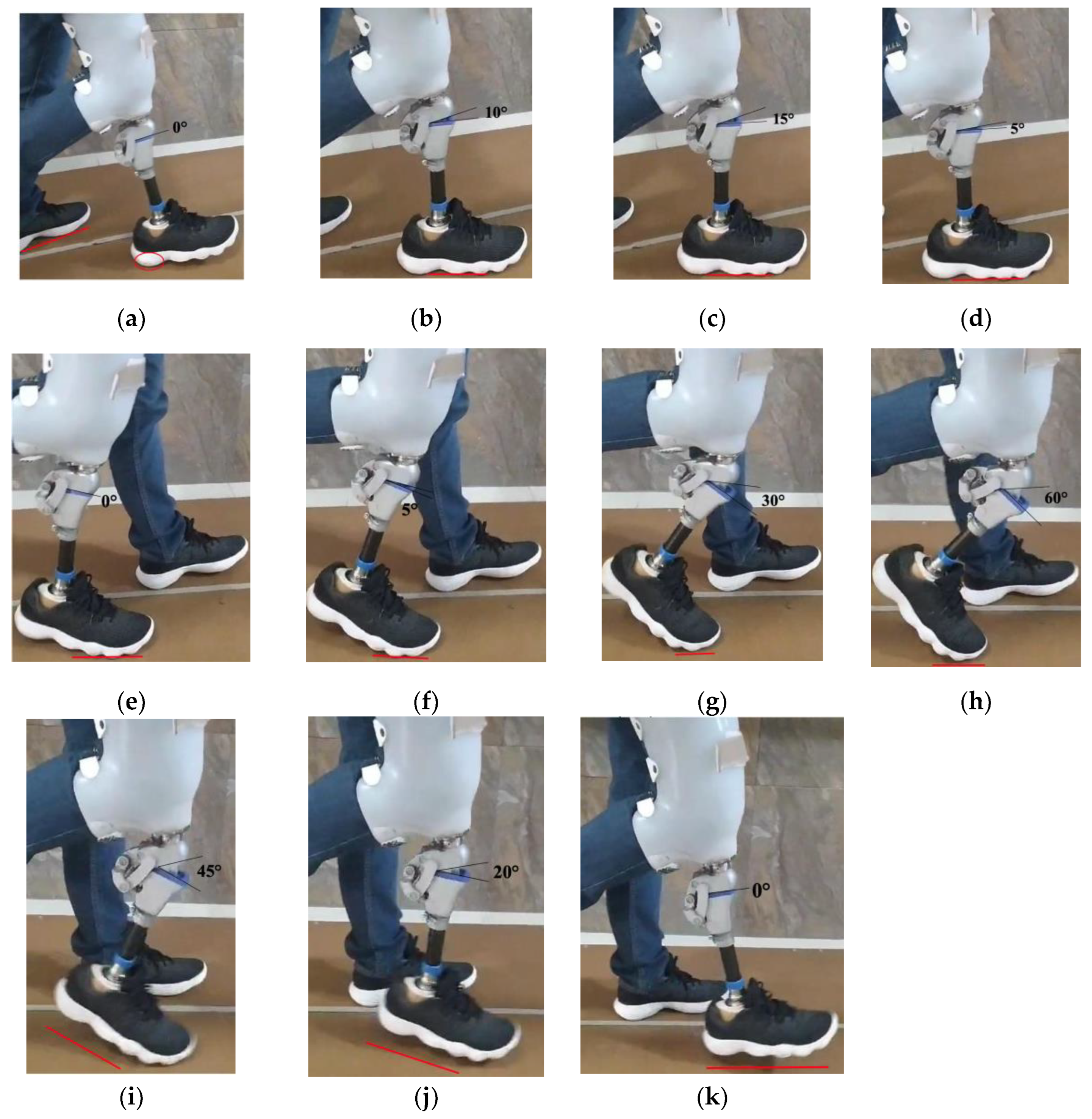
Figure 12.
Gait Cycle of Model 3 During Functionality Tests.
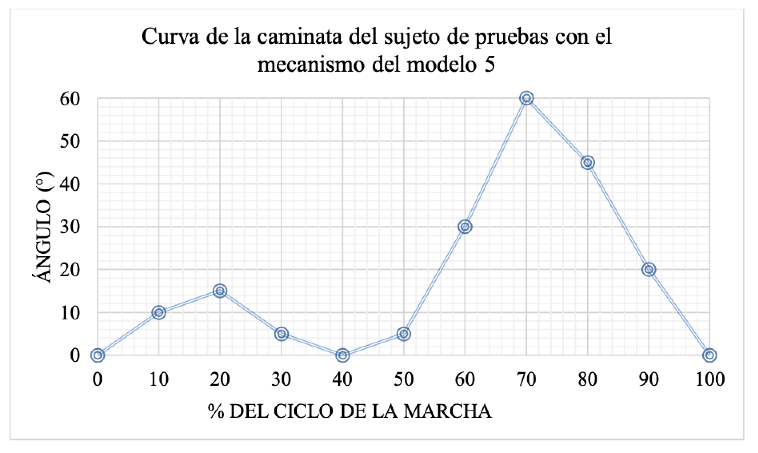

Table 1.
Positioning of the knee´s Anatomical Reference System.
| Description | Value (mm) |
|---|---|
| Suggested Position of the ICR origin Relative to the Anatomical Center of the Knee. | 100 |
| Suggested Position of the ICR Origin Relative to the Anatomical Axis of the Leg. | 6 |
Table 2.
Lineamientos de diseño del mecanismo para prótesis externa de rodilla.
| Criterio | Estrategia |
|---|---|
| Range of Motion | Adjust size of the links to match the trajectory of the target curve. |
| Functional and Aesthetic Design | Consider the quantitative parameters to create an aesthetically pleasing design |
| Ensure Voluntary Control | Verify that the position of the ICR, along with the mechanism and the leg, lies within the stability zone. |
| Comfort | Replicate the target ICR. Add flexible material to absorb impact during the stance phase, reducing load and shock on the residual limb. Consider a spring that enables the foot to return at the end of swing phase. |
| Hyperextension | Limit the range of motion to prevent potential injuries. |
Table 3.
Dimensions model 1.
| Figure | Link | Length [mm] | Angles (Deg) |
|---|---|---|---|
 |
A | 128 | 46.02 |
| B | 28 | 143.53 | |
| C | 79.50 | 121.94 | |
| D | 45 | 48.51 | |
| B and the leg axis | 25 | 33.2 |
Table 4.
Dimensions model 2.
| Figure | Link | Length [mm] | Angle (Deg) |
|---|---|---|---|
 |
A | 61 | 102.64 |
| B | 16.50 | 89.12 | |
| C | 35.33 | 130.43 | |
| D | 38 | 37.81 | |
| B and the leg axis | 35.5 | 34 | |
Table 5.
Gear Train Specifications.
| # teeth | Pitch Diameter | Outer Diameter | Base Diameter |
|---|---|---|---|
| N1 = 15 | Module m=1 | Addendum → a = 1/1 | Pressure Angle → u=20 |
| N2 = 14 | Dp1 = N1 . m = 15 | Db1 = Dp1 . cos 20 = 14.095 | Db1 = Dp1 . cos 20 = 14.095 |
| NL = 14 | Dp2 = N2 . m =14 | Db2 = Dp2 . cos 20 = 13.156 | Db2 = Dp2 . cos 20 = 13.156 |
Table 6.
Dimensions and Positioning of the Mechanism and Gear Train.
| Figure | Link | Lenght [mm] | Angle (Deg) |
|---|---|---|---|
 |
A | 61 | 102.64 |
| B | 16.50 | 89.12 | |
| C | 35.33 | 130.43 | |
| D | 38 | 37.81 | |
| E | 43.81 | 21.36 | |
| F | 28.5 | 173.08 | |
| G | 18.81 | 107.84 | |
| H | 18.80 | 74.44 | |
| B and reference line | 35.50 | 163.28 |
Table 7.
Discrete Fréchet Distance Between the Main Models and the Target ICR Trajectory.
| Comparison | Discrete Fréchet Distance (mm) |
|---|---|
| Reference Curve vs. Model 1 | 50.90 |
| Reference Curve vs. Model 2 | 14.46 |
| Reference Curve vs. Model 3 | 5.33 |
Disclaimer/Publisher’s Note: The statements, opinions and data contained in all publications are solely those of the individual author(s) and contributor(s) and not of MDPI and/or the editor(s). MDPI and/or the editor(s) disclaim responsibility for any injury to people or property resulting from any ideas, methods, instructions or products referred to in the content. |
© 2025 by the authors. Licensee MDPI, Basel, Switzerland. This article is an open access article distributed under the terms and conditions of the Creative Commons Attribution (CC BY) license (http://creativecommons.org/licenses/by/4.0/).
Copyright: This open access article is published under a Creative Commons CC BY 4.0 license, which permit the free download, distribution, and reuse, provided that the author and preprint are cited in any reuse.


