
Submitted:
14 October 2025
Posted:
15 October 2025
You are already at the latest version
Abstract
The San Niccolò’ Tower-Gate in Florence, designed by Andrea dell'Orcagna, was built in 1328 as part of the third ring of the city walls of Florence. In the frame of a conservation project promoted by the Municipality of Florence, the Department of Earth Sciences of the University of Florence conducted a series of studies, using NDT techniques, to characterize the tower's masonry. Based on geological, seismic, georadar, sonic, and scleometric investigations, the Tower's masonry was found to had been excellently constructed and, after eight centuries, remains in good condition.
Keywords:
medieval
; masonry
; tower-gate
; ndt
; anatomy
1. Introduction
Conservation of historic buildings deserves special attention, because they are not only a distinctive feature the wisdom and creativity of the ancients, conveying abundant historic and technical information, but often they also are the symbol of a culture and represent the local community as a whole [1,2].
At the same time, in addressing the problem of their conservation we meet important constraints in devising remedial measures and interventions, due to the need of preserving the “Authenticity” and “Integrity” of the building.
Authenticity implies no pieces substitution or substitution with the same material from the same source (same stone type from the same quarry) worked and placed according to the original traditional methods.
In considering the vulnerability of built heritage, it is important distinguish between the “Intrinsic Vulnerability” and the “Induced Vulnerability” for further details on references.
Intrinsic Vulnerability is linked to the conception of the building, the used materials, the construction techniques and all changes or modification that took place during its span live. Buildings affected by severe Intrinsic Vulnerability have already suffered damages and lost their Integrity; they can be repaired only losing their Authenticity. Historic Integrity includes foundation.
Induced Vulnerability is linked to the reduction in time of the quality of the construction, due to the natural decay of properties of the materials constituting the masonry apparatus or to induced decay due to violent external inputs like earthquakes, wars, revolutions and spoliation, pollution …
The essence of Conservation is to remove any cause of Added Vulnerability in order to elongate the life of the building; Conservation includes many items:
- -
- Protection from decay
- -
- Restoration of damages: structural/aesthetic
- -
- Recovering/restyling/integration
- -
- Lasting of the functional use
- -
- Maintenance with same material and techniques
Scientific, technical, historical knowledge are fundamental in order to recovery traditional and original craft knowledge and operative techniques. Today, numerical informative contents 2D and 3D (GIS, H-BIM) are available for achieving and handling down this knowledge.
In order to preserve Integrity and Authenticity, Maintenance is fundamental; that means a continuous work for controlling the Integrity of the building and in need Restoration interventions for its Conservation according to the Authenticity principle.
A fundamental work is played by daily ordinary monitoring and maintenance plus spot extraordinary interventions in event of necessity, for that a constant flux of money is in need.
In ancient times, the endowment of real estate and property of temples or religious complexes was intended for their sustenance and maintenance, or were under the patronage of a public or private institution that took care of their maintenance. This and the persistence of use and functions guarantee the conservation of the building heritage.
The lack of this leads to decadence, ruin and the need for extensive and costly conservation interventions.
In Italy, the Guidelines of the Ministry of Culture [3] dictate the rules to follow for a correct conservation process (Figure 1). In particular, at Point 6.1.6 they ask for NDT: no destructive techniques of indirect type (thermography, georadar, sonic tomography, etc.), or LDT: low destructive direct inspections (DAC-Test, endoscopies, descaling of plasters, small explorations, etc.).
In October 2022, the Firenze Municipality and the Department of Earth Science of the Firenze University developed a joint research project regarding the San Niccolò’ Tower-Gate regarding:
- -
- Geometric survey via laser scanner and photogrammetry by ground and drone aimed at creating a 3D model in H-BIM.
- -
- Execution of technical surveys for characterizing the masonries through NDT and LDT surveys.
- -
- Classification of the masonries according to different approaches.
- -
- Characterization of the foundations.
1.1. San Niccolò’ Tower-Gate History
The San Niccolò’ Tower-Gate is part of the III city ring-wall built in the XIV century, specifically the Tower was built in 1328 based on a design by Andrea dell’Orcagna, by the workers of the Opera del Duomo to whom the construction had been contracted.
During the siege of Florence in 1530, the Tower was not decapitated and reduced to a gun-port, like all the others, because the hill around and the Fort of San Miniato protected it from the shots of the Imperial artillery; thus remaining the only Florentine Tower-Gate to retain its original height of 70 Florentine arms (about 40 m).
The Tower was equipped with an ante-door and a quadrangular external redoubt that through some turrets connected it to the San Niccolò weir, a natural continuation of the city ring-walls across the Arno River.
During the works for Florence Capital in 1870 coordinated by the Arch. Poggi, all the structures near the tower were demolished leaving it isolated like an obelisk in the centre of the perspective of the Rampe (Figure 2); on this occasion the external stairs for access to the tower were added on the Rampe side [4].
The original battlements and corbels had deteriorated over time and had been demolished. On the façade, in the restorations of the 1930s, the corbels were rebuilt to support a projecting walkway, with machicolations, protruding overall by 1.5 m; the battlements, 45 cm thick, were reconstructed along the entire top floor of the Tower [5].
2. Materials and Methods
2.1. Geometric Survey
The San Niccolò’ Tower-Gate presents two lateral piers of about 10 m x 3.3 m joined frontally by a 2 m thick curtain with the door. The two piers are connected above the access space by central and rear arches that support the wooden platforms of the two intermediate floors, while in the current configuration the roof vault was made up of a gable roof.
A laser scanner survey of the Tower was performed, with Cam2 Faro Focus S70 and Zoller+Fröhlich IMAGER 5016 instruments, subsequent processed in AUTODESK RECAP Pro (©AutoDesk). In order to be able to create correct photo-plans to be mounted on the 3D model, the survey was completed by a series of photographs taken using a drone (EliteConsulting Dji HH_PH4RTK-040 - with flight performed by Studio Micheloni S.R.L. as part of an active collaboration with the DST) and from the ground, taken with a SONY α6500 camera.
The graphic restitution was implemented in a H-BIM environment by means of AUTODESK REVIT (©AutoDesk) (Figure 3).
2.2. The Masonry
The masonry of the Tower consists of irregular courses of Pietraforte sandstone blocks approximately 20 cm high, bonded with mortar in layers approximately 2 cm thick. The two main facades, east and west, are finished with regular courses of Pietraforte facing quoins, of uniform size, approximately 40 cm high, 60 cm long, and 30 cm thick, forming an integral part of the masonry (Figure 4a).
The corbels at the ridge of the east elevation, reinstated in the 1930s, are made with overlapping beams of Pietra Serena sandstone (Figure 4b).
2.3. Georadar Survey
The GPR were performed using a Stream-T radar and a C-Thrue radar, produced by IDS Georadar s.r.l. (part of Hexagon).
The Stream-T, used for the investigations carried out on the external walls, represents a new generation of GPR antennas that operate contactless with the surface of the object to be investigated. The antenna consists of 3 antenna modules connected in a continuous chain (width 90 cm – Figure 4) that work at 900 MHz, with horizontal polarization, remaining approximately 15 cm from the investigated surface.
The C-Thrue, used to investigate attics, battlements and corbels, is equipped with two pairs of orthogonal polarity antennas at a peak frequency of 1500 MHz that allows for high detail but with a limited investigable thickness (< 70 cm).
The georadar analysis of the external walls of the Tower was carried out with the Stream-T antenna which, mounted on the external edge of a lifting basket (Fig,4), was lifted to perform sequential scans of the facades of the Tower (Figure 5a). The lifting of the basket was carried out for keeping the Stream-T antenna parallel, and at a small distance (about 20 cm), from the wall.
The georadar scans, which extend to a depth of approximately 2 m, identify evident surface reflections in the first 30-50 cm above a homogeneous body not associated with evident discontinuities and/or structural criticalities. This trend of reflections present in the radargrams is consistent with an external curtain of facciavista quoins, with a thickness of approximately 30-50 cm, followed by a full and compact masonry, and seem to exclude significant voids and/or cavities (Figure 5b).
The georadar survey on the battlements was carried out using a C-Thrue radar (Figure 6). The high frequency of the electromagnetic wave makes the C-Thrue particularly efficient in analyses aimed at the internal characterisation of bodies of limited thickness and is therefore the ideal tool perfect for analysing the battlements with a thickness of 40 cm, with the aim of evaluating the possible presence of metal elements inserted inside.
The analysis of the radargrams suggests an irregular structure with smaller stones in correspondence with the balustrade, and a structure with homogeneous quoins in the battlement above the balustrade; the mortar interposed between distinct quoins is well detected by reflections.
The intermediate and the top floors were surveyed by C-Thrue through a series of linear acquisitions, North-South and East-West oriented, which, with a spacing of 50 cm, cover the entire surface of the floors.
The acquisitions carried out on the inter-storey slabs have highlighted a slab of about 15 cm that rests on the beams oriented East-West, which in turn rest on the central arch with North-South development. The masonry above the arch, visible from the scans carried out in the West-East direction appears to have a compact and homogeneous structure and no disconnections are evident (Figure 7).
The radargrams of the scans carried out on the terrace of the top floor, are regular for the entire thickness analysed (about 50 cm), where they identify a superficial layer of about 10 cm that an exploratory test has attributed to paving, bedding mortar and a stratification of waterproofing sheaths, all of which overlap the underlying screed and the tiles.
In order to provide a detailed knowledge of the setting of the corbels on the Tower’s wall structure, an additional analysis involved the western portion of the summit walkway, where 7 scans were performed parallel to the eastern wall of the Tower and with a spacing of 30 cm. The results highlight the characteristic reflections of the vaults that support the battlements of the eastern facade of the Tower starting from a depth of about 1.5 m, the reflections produced by the stone bars that constitute the corbels (Figure 8). The analysis of these scans highlighted that the reflections by the bars of the corbels are detectable up a distance of about 190 cm from the external side of the battlements, suggesting a clamping of the bars in the masonry of the Tower of about 40 cm.
2.4. Sonic Survey
Using a Novasonic U5200 CSD sonic instrumentation from IMG Ultrasuoni srl, a direct transmission sonic survey campaign was carried out on the masonry of the Tower-gate and on corbels and battlements.
For the corbels, 18-point sonic measurements were done on each single corbel (Figure 9); for each point, in order to obtain a more representative value, multiple acquisitions were made. The investigations on the corbels show a general decrease in velocities in the outermost portion of the top stone-bars, which indicate a decrease in mechanical characteristics linked to an increase in internal fracturing and alteration. The maximum velocity values found on a single segment (> 6,000 m/s) are compatible, in fact, with a compact rock, while the minimum values (900 m/s) suggest a significant degree of alteration. Considering the 11 corbels, as evident from the overall results a situation of greatest alteration is found in the external corbels (1 and 11) and in those adjacent to the grates of the summit terrace.
For battlements, the velocity values measured on single quoins are between 4,600 and 5,600 m/s, suggesting a good state of conservation. A significantly lower sonic velocity (1,322 m/s) had been recorded at the base of battlement 8, indicating a poor degree of conservation. For the battlement masonry, the measured values vary from 481 m/s 2,051 m/s; that suggests a deep influence of the mortar quality.
Sonic investigations on the walls allowed us to attribute values of Vp = 2,900 m/s to the masonry of the piers and Vp = 2,800 m/s to the masonry of the front curtain wall; those of the Vs, carried out at the base of the northern pillar, returned values of Vs = 1,920 m/s. The ratio between these two values leads to estimate the Poisson’s ratio = 0.13, which corresponds, given the estimated volume weight of 23 kN/m3, to a Rigidity value G = 8.4 GPa and a Young’s Modulus E = 19 GPa. The combination of these values defines a high degree of compactness of the masonry as a whole, even on considerable thicknesses.
2.5. Sclerometric and Penetrometric Surveys
Sclerometric tests were carried out on the stones in place using the Schmidt hammer N-type 58-C0181/N, by Controls, according to [6,7]. The results of the sclerometric tests generally have given JCS values up to 170 MPa, which is an indication of a good-excellent state of conservation for the stones in place; tests deliberately carried out on few evidently degraded stones gave values around 70 MPa.
Penetrometric test on mortar was performed using DRC instrumentation with metal tip insertion and measurement of the insertion in mm after 10 blows; the tests were conducted on the original medieval mortars used to set the stones. The resistances of the mortars were obtained using a correlation curve and formula and resulted to be very good, with an average of around 20 MPa, in line with the literature results for medieval Florentine mortars [8] always made by the workers of the Opera del Duomo in the same times.
2.6. DAC-Test and Endoscopy
In order to investigate the structure and the masonry texture of the Tower, 16 DAC-Tests (Drilling Advancing Consistence Test) were performed with relative endoscopy.
The drills, performed with a 16 mm Ø tip, were pushed inside the masonry for 120 cm, the maximum depth possible with tips of this diameter, located at a height of approximately 120-150 cm from the floor levels.
The control of the competence of the masonry to the perforation and the observation of the cuttings led to considering the masonry well-constructed and compact, without internal voids, internally dry (even if carried out on drizzly days).
For the two piers, we estimated a mortar/stone ratio equal to approximately 70% stones and 30% mortar for the masonry from the ground to the second floor, and approximately equal to 55% stones and 45% mortar for the masonry from the second floor to the top.
These values are in line with those for Giotto’s Bell Tower [9] and for Brunelleschi’s Dome [8] and are therefore to be considered typical of the masonry of the period carried out by the workers of the Opera del Duomo. On the first and second floors, drills carried out on the internal facings of the Tower have frequently seen the identification of voids of small dimensions after the first stone curtain, beyond which the masonry appears compact and well-woven.
2.7. Foundations
The availability in the geological database of the Firenze Municipality (https://sigs.comune.fi.it/) of 6 boreholes all around the site of the Tower and a historical painting (Figure 10) allowed to define that the Tower is directly founded onto the bedrock about 3 m at depth.
Field and boreholes data, matched with historical data of the Arno banks evolution, led to define the geological setting of the Tower slope (Figure 11).
2.8. Seismic Setting
Based on catalogue locations, the city of Florence has been the epicentre of major earthquakes that have occurred in historical times, with estimated magnitudes always being less than 5 ML [10], resulting in local earthquakes with Imax = VIII on the MCS (Mercalli-Cancani-Sieberg) scale.
The main seismic events that caused damage in the Florence area are those of the years 1453, 1895 and 1919 with an estimated magnitude 5.4; Imax MCS VII-VIII.
In the case history of the San Niccolò’ Tower-Gate, foundations rest directly on a rigid substrate, therefore the input seismic signal for the seismic hazard assessment, as referred to a set of 7 natural accelerograms, recorded on rock and spectrocompatible for a return period of 712 years, as it is a historic-monumental building, gives a maximum acceleration equal to 0.57g; to be compared with the proper moment of the Tower (Figure 12).
By means of a set of 13 seismometers located at different levels on the Tower (Figure 13) it has been possible, using ambient noise, to define the proper motion of the Tower.
The instrumentation used for the thirteen stations consists of thirteen Lennartz 3D/1sec seismometers, with a sensitivity of 800 V/m/s, and an accuracy of 1 μm/s @ 1Hz. The seismic data were acquired and stored with 24-bit digitizers (Guralp CMG-DM24) at a sampling rate of 500 Hz, ensuring a spectral range (0.5-250 Hz) sufficient for a complete description of the structure.
Having completed the analysis of the instruments underlying the EFDD technique for determining the system’s dynamic parameters, such as natural frequencies, mode shapes, and damping, we now move on to the actual analysis of the building under examination.
The results obtained clearly identify five modal shapes (Figure 14), with frequency peaks of 1.552 Hz, 1.666 Hz, 3.725 Hz, 5.612 Hz, and 8.080 Hz. The first two flexural modes being coupled and exhibiting a frequency difference of only 0.11 Hz. The first modal shape exhibits a north-south motion perpendicular to the second mode, which is primarily east-west. The third mode, at a frequency of 3.725 Hz, is torsional, while the fourth and fifth are flexural, with north-south and east-west motion directions, respectively.
3. Results
The data deriving from the NDT analysis performed allowed to define that the Tower’s masonry is in an excellent state of preservation throughout the entire structure, although the situation is different with regard to the local deterioration of some individual stones or structures.
Regarding the Pietraforte sandstone, it appears, after approximately 700 years, to be in a more than good state of preservation. Only a few minor surface exfoliations are locally present, essentially related to individual stone elements, placed with stratigraphic laminations parallel to the external surface and therefore subject to deterioration.
The Pietraforte sandstone used in the 1930s restoring works for the battlements, generally appears to be of lower quality, with several ferruginous inclusions and often installed askew. This positioning has undermined its state of conservation approximately 100 years after installation, with evident signs of widespread deterioration, both in terms of exfoliation and the detachment of significant stone portions.
The results of the georadar surveys and observations in the areas with missing parts show that the Pietraforte quoins in place are perfectly squared, laid with a thin layer of connecting mortar, without any significant internal flaring or mortar bonding.
Regarding the corbels, the Pietra Serena sandstone beams, which have been in place for approximately 100 years ago, show evident surface degradation, already slightly repaired in previous restorations, caused by heavy exposure to rainwater and water percolating from the upper walkway. This aspect is clearly highlighted by the results of the georadar, sonic, and rebound hammer tests performed.
The comparison of the measured sonic velocities (Vp) and the rebound index (R) from the rebound hammer test, both indicative of the cortical state of the material investigated, provides a clear indication of the level of degradation of the Pietra Serena sandstones of the corbels (Figure 15).
The investigations carried out revealed a substantial uniformity of the walls. The only minor differences that emerged concernes the mortar/stone ratio, which for the two piers was approximately 70% stone and 30% mortar for the walls from the ground to the second floor, and a lower ratio of approximately 55% stone and 45% mortar for the walls from the second floor to the ridge. This corresponds to an estimated density of = 23.6 kN/m3 and = 22.3 kN/m3, respectively; endoscopic analysis showed the front curtain wall is slightly less compact, with a mortar/stone ratio of around 50%, corresponding to = 21.9 kN/m3.
The determined sonic velocities were of the order of magnitude Vp = 2,800 m/s for the piers, and Vp = 1,900 m/s for the front curtain wall, thus confirming a difference in performance between the two masonry structures.
The masonry of the San Niccolò’ Tower yielded Poisson’s ratio = 0.13, stiffness G = 8.4 GPa, and Young’s modulus E = 19 GPa; these values are similar to those of other contemporary monumental buildings in Florence, for which, thanks to previous investigations, the following reference data are available: UCS (σc) = 15.1 MPa and Young’s modulus E = 20 GPa.
All these values are significantly higher than those listed in the Italia Normal, but in line with the properties of the materials and mortars as known for the medieval age. In this regard, it should be noted that the Normal values refer to walls with an ordinary thickness of up to approximately 1.5 m, while here the piers have a masonry thickness around 3 m.
According with different approaches, the masonry of the San Niccolò’ Tower-Gate can be classified as in Table 1.
4. Conclusions
Based on the results achieved, it can be stated that the Tsan Niccolò’ Tower-Gate in its current configuration can be considered to fully fit with the concepts of Integrity and Authenticity, that it is in a good general state of conservation with no intrinsic or induced vulnerabilities and therefore in good health and without structural defects that compromise its conservation.
| Conservation Compliance Checklist for the San Niccolò’.Tower-Gate | ||
| Principle | Situation | Verified |
| AUTHENTICITY | Reconstruction of the battlements and corbels with the same materials | YES |
| INTEGRITY | Few repaired cracks, no structural collapse or missing primary elements, or replacements | YES |
| MONITORING | Systematic periodic checks, including those performed with a lift basket | YES |
| MAINTENANCE | Regular routine maintenance and periodic extraordinary maintenance. | YES |
Author Contributions
Conceptualization, M.C. and C.S.; methodology, M.C.; software, A.C. and E.M.; validation, M.C. and C.S.; formal analysis, A.C. and E.M.; investigation, M.C., A.C., G.L. and E.M.; resources, M.C.; data curation, A.C. and E.M.; writing—original draft preparation, M.C.; writing—review and editing, A.C. and E.M.; supervision, C.S.; project administration, M.C.; funding acquisition, G.C.. All authors have read and agreed to the published version of the manuscript.
Funding
This research was funded by Municipality of Firenze, Servizio Belle Arti, grant number VANN22COMFIRENZE_TorSan.
Acknowledgments
We acknowledge the personal of the offices of the Firenze Municipality and the technical staff of the Department of Earth Sciences for the help in developing this study. During the preparation of this manuscript/study, only editor English orthographic corrector and no AI support has been used. The authors have reviewed and edited the output and take full responsibility for the content of this publication.
Conflicts of Interest
The authors declare no conflicts of interest.
References
- Coli, M. , Iwasaki, Y. Novel Approaches and Technologies for Heritage Buildings Conservation: Editorial. Appl. Sci. 2021, 11, 10597, 1-6. [Google Scholar] [CrossRef]
- Coli, M. , Caciagli, S., Agostini, B., Ciuffreda, A.L. Principles and practices for conservation of historical buildings: the case history of the Saint John Baptistery at Florence, Italy. In R. Lancellotta, C. Viggiani, A. Flora, F. de Silva and L. Mele Eds, “Geotechnical Engineering for the Preservation of Monuments and Historic Sites III”, CRC Press/Balkema, Taylor & Francis Group, 3088; -7, 2022 313-324. ISBN 978-1-003-30886-7. [Google Scholar] [CrossRef]
- DPCM 9/2/2011 – Decreto Presidenza Consiglio Ministri “Linee guida per la valutazione e riduzione del rischio sismico del patrimonio culturale, con riferimento alle norme tecniche per le costruzioni”. Gazzetta Ufficiale GU Serie Generale n.47 del 26/02/2011 Zecca, Supplemento Ordinario n. 54, 2011.
- Poggi, G. , Sui lavori per l’ingrandimento di Firenze 1864-1877. Tipografia di G. Barbera, Firenze, 1882, 374 pp.
- Giannelli, L. , Semplici, R. I Lungarni Fiorentini si raccontano. Scramasax Ed., Firenze, 2019, 175 pp.
- UNI-EN 14579:2005; Metodi di Prova per Pietre Naturali - Determinazione della Velocità di Propagazione del Suono. Ente Nazionale Italiano di Unificazione, 2005. Available online: https://www.uni.com/ (accessed on 27 July 2022).
- A., Aydin Upgraded ISRM Suggested Method for Determining Sound Velocity by Ultrasonic Pulse Transmission Technique. Journal Rock Mechanics and Rock Engineering, 2014, 47, 255–259.
- Barbi, L. , Leggeri, B., Vasari, V., Franchi, R., Fratini, F., Manganelli del Fa, C. Indagine sperimentale sui materiali costituenti la Cupola di Santa Maria del Fiore. Un. Firenze, Facoltà di Architettura, Atti Dip. Costr, 1986, 1, 5-78.
- Coli, M. , Baldi, M., Tanganelli, M., Viti, S. The Giotto’s Bell-Tower at Firenze (Italy): foundation assessment. Journal of Cultural Heritage Management and Sustainable Development, © Emerald Publishing Limited 2021 2044-1266, 16 pp. [CrossRef]
- Coli, M. , Lacanna, G., Ripepe, M. Pericolosità di base e sismicità storica. In “La microzonazione sismica e le analisi delle condizioni limite per l’emergenza del Comune di Firenze, I libri della Giunta Regionale, 2022,Territori, 13-23 https://www.regione.toscana.it/-/la-microzonazione-sismica-e-le-analisi-delle-condizioni-limite-per-l-emergenza-del-comune-di-firenze?inheritRedirect=true&redirect=%2Fsearch%3Fq%3Dfirenze%26orderBy%3Dhits%26sortBy%3Ddesc%26type%3Dcom.liferay.journal.model. JournalArticle ISBN 0978-88-7040-137-0.
- Manuale per il rilevamento della vulnerabilità sismica degli edifici. DNPC. Dipartimento Nazionale Protezione Civile 1993, 36 pp. https://protezionecivile.regione.abruzzo.it/agenzia/files/rischio%20sismico/verificheSism/Manuale_e_scheda_GNDT_II_livello.pdf.
- AA.VV. Abaco delle murature della Regione Toscana, Firenze, Ottobre 2019, https://www.regione.toscana.it/-/abaco-delle-murature-della-regione-toscana.
- C-MIT 7/2019 - Istruzioni per l’applicazione dell’“Aggiornamento delle Norme Tecniche per le Costruzioni” di cui al decreto ministeriale 17 gennaio 2018. Ministero delle Infrastrutture e dei Trasporti, Circolare n. 7 del 21/01/2019, Gazzetta Ufficiale Serie Generale n.35 del 11/02/2019 - Supplemento Ordinario n. 5, 2019.
Figure 1.
Knowledge path defined by the Italian rules (elaboration A.L. Ciuffreda).
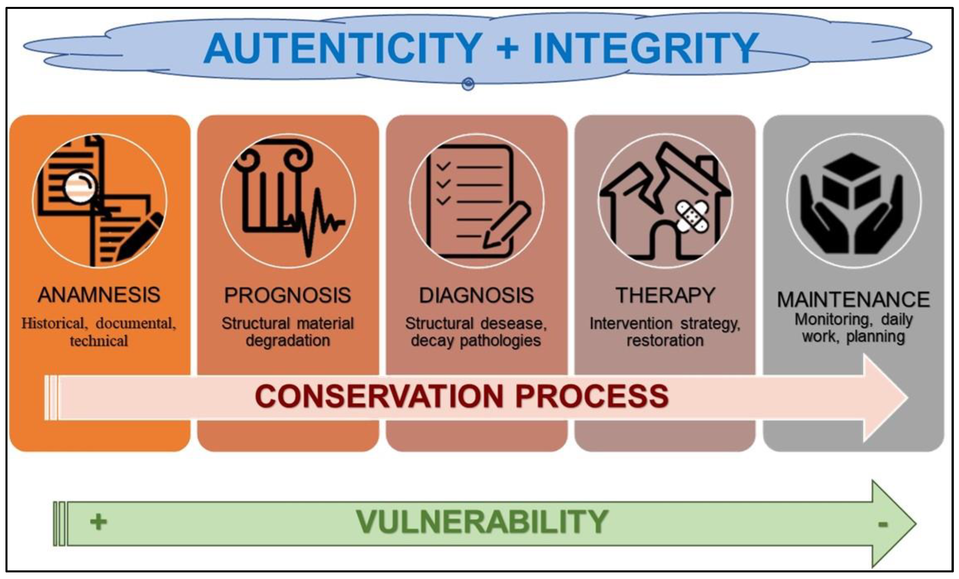
Figure 2.
1880 c. historical photo, the Poggi ramps with the Torre di San Niccolò acting as a reference obelisk (image by public domain).
Figure 2.
1880 c. historical photo, the Poggi ramps with the Torre di San Niccolò acting as a reference obelisk (image by public domain).
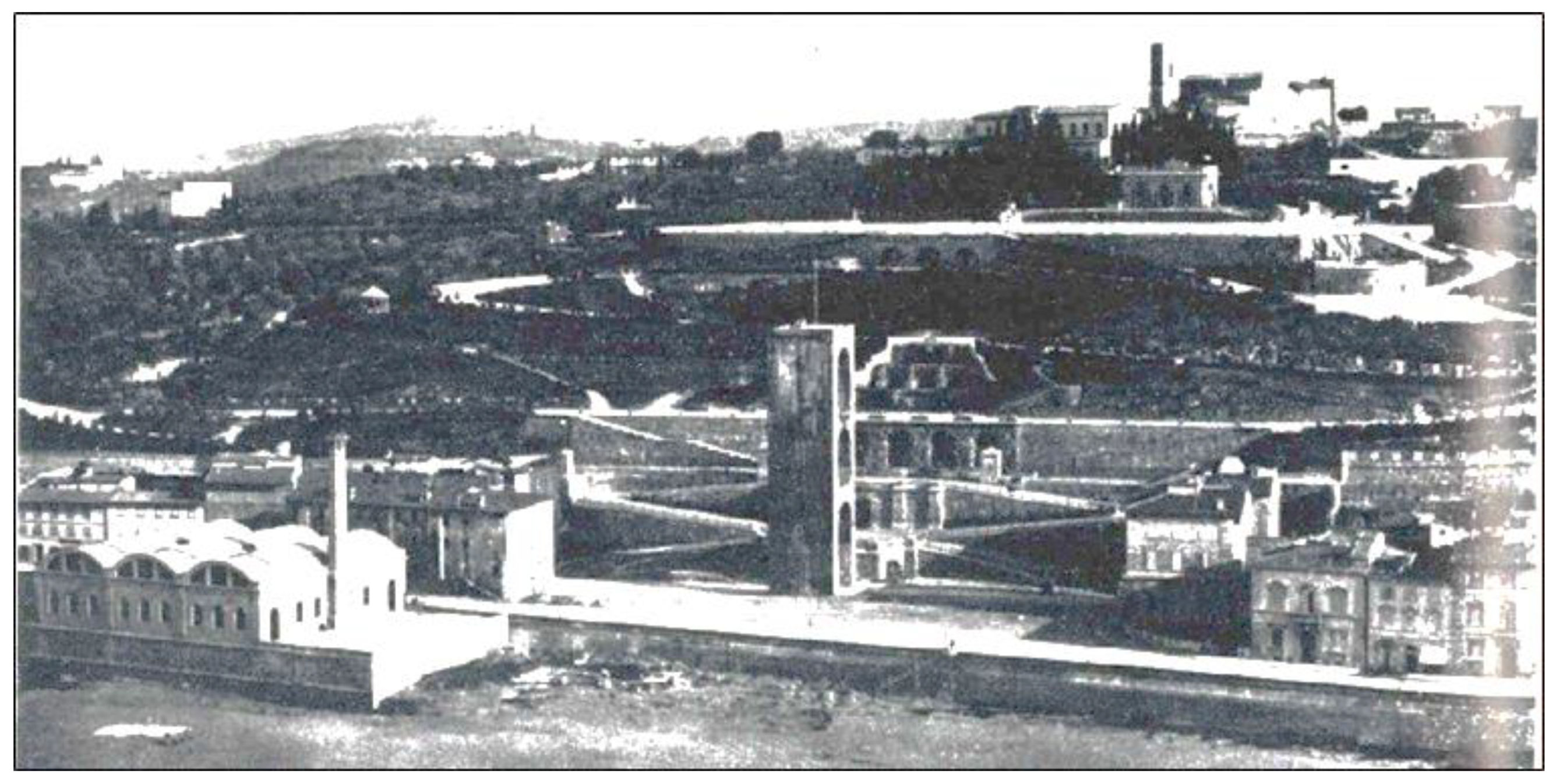
Figure 3.
From left: drone photogrammetric survey, point-cloud restitution, H-BIM model (elaboration A.L. Ciuffreda).
Figure 3.
From left: drone photogrammetric survey, point-cloud restitution, H-BIM model (elaboration A.L. Ciuffreda).
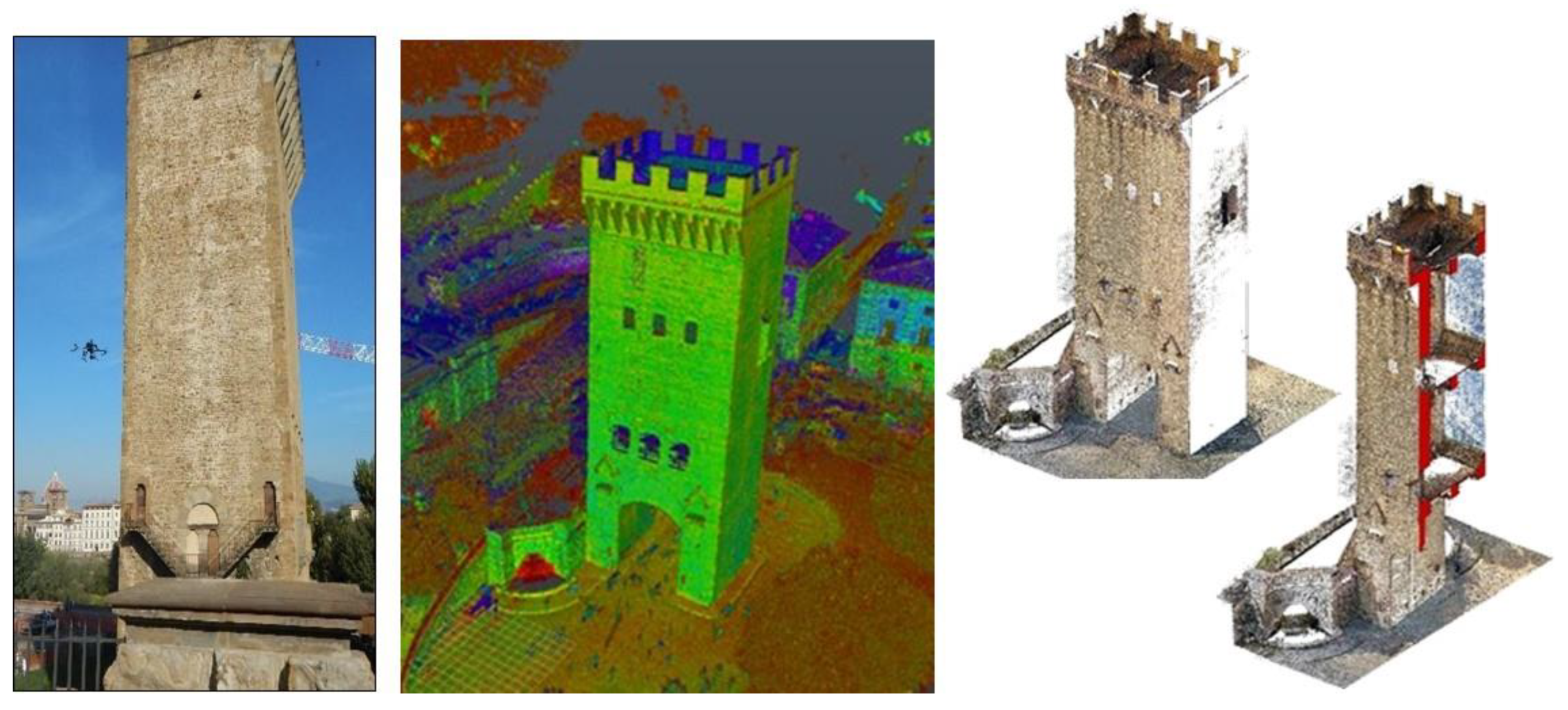
Figure 4.
Left: Ordinary masonry facing made of Pietraforte sandstone elements and mortar; right: corbels in Pietra Serena sandstone on the east side. To be noted the GPR antenna mounted the external of a lift-basket for executing the GPR survey of the Tower facades.
Figure 4.
Left: Ordinary masonry facing made of Pietraforte sandstone elements and mortar; right: corbels in Pietra Serena sandstone on the east side. To be noted the GPR antenna mounted the external of a lift-basket for executing the GPR survey of the Tower facades.
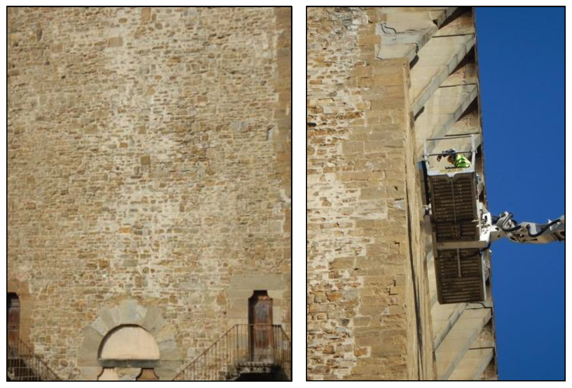
Figure 5.
a) layout of the GPR scanlines on the outer facades; b) example of radargrams mounted in their proper position showing the structure of the masonry (elaboration A.L. Ciuffreda).
Figure 5.
a) layout of the GPR scanlines on the outer facades; b) example of radargrams mounted in their proper position showing the structure of the masonry (elaboration A.L. Ciuffreda).
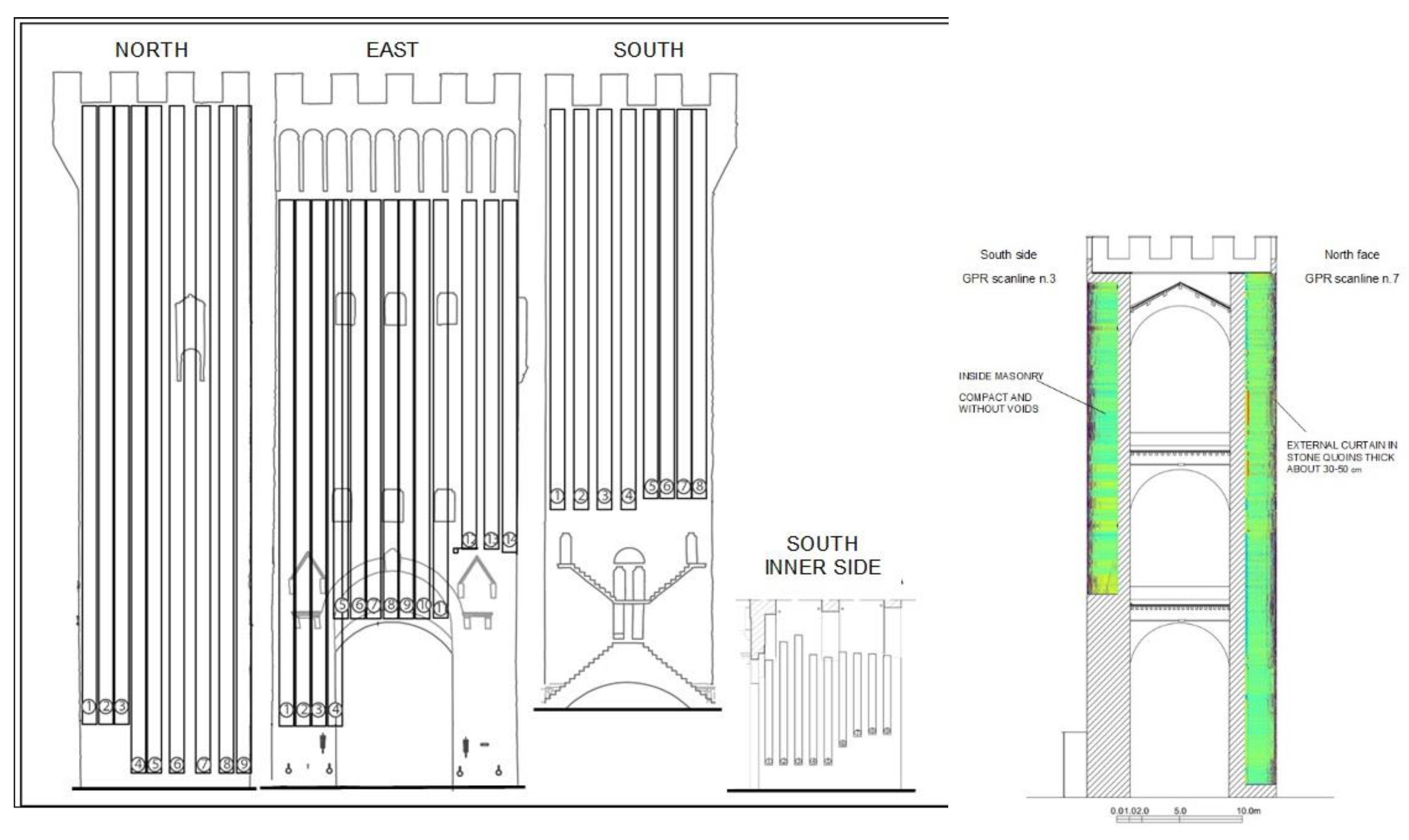
Figure 6.
Layout of the GPR scanlines on the battlements and one moment of the survey (elaboration E. Marchetti, photo M. Coli).
Figure 6.
Layout of the GPR scanlines on the battlements and one moment of the survey (elaboration E. Marchetti, photo M. Coli).
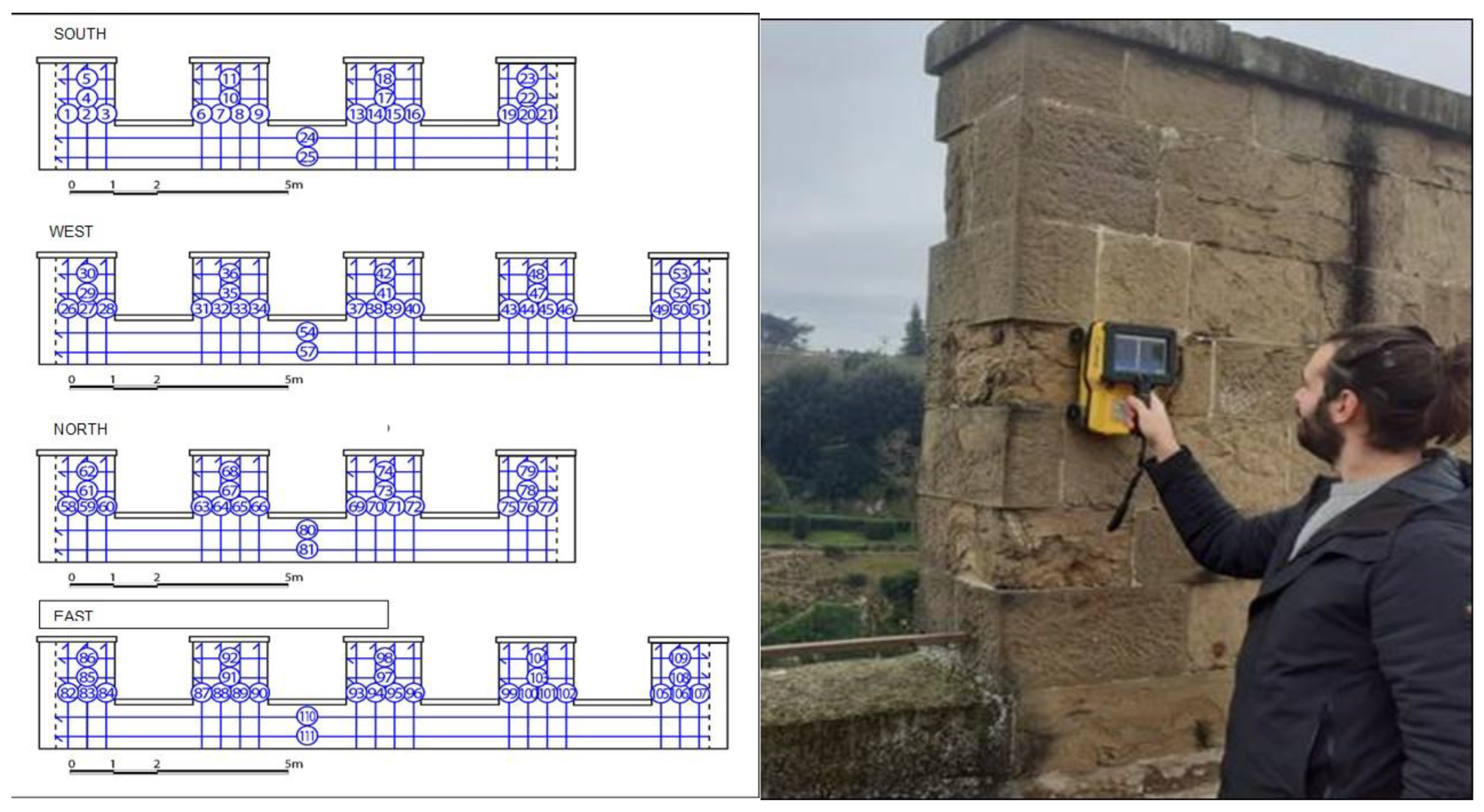
Figure 7.
Slices of the tomographic analysis carried out on the second floor showing the beam structure that is inserted into the load-bearing arch at a depth of approximately 20 cm (a) and the homogeneous structure of the load-bearing arch at a depth of approximately 28 cm (b).
Figure 7.
Slices of the tomographic analysis carried out on the second floor showing the beam structure that is inserted into the load-bearing arch at a depth of approximately 20 cm (a) and the homogeneous structure of the load-bearing arch at a depth of approximately 28 cm (b).
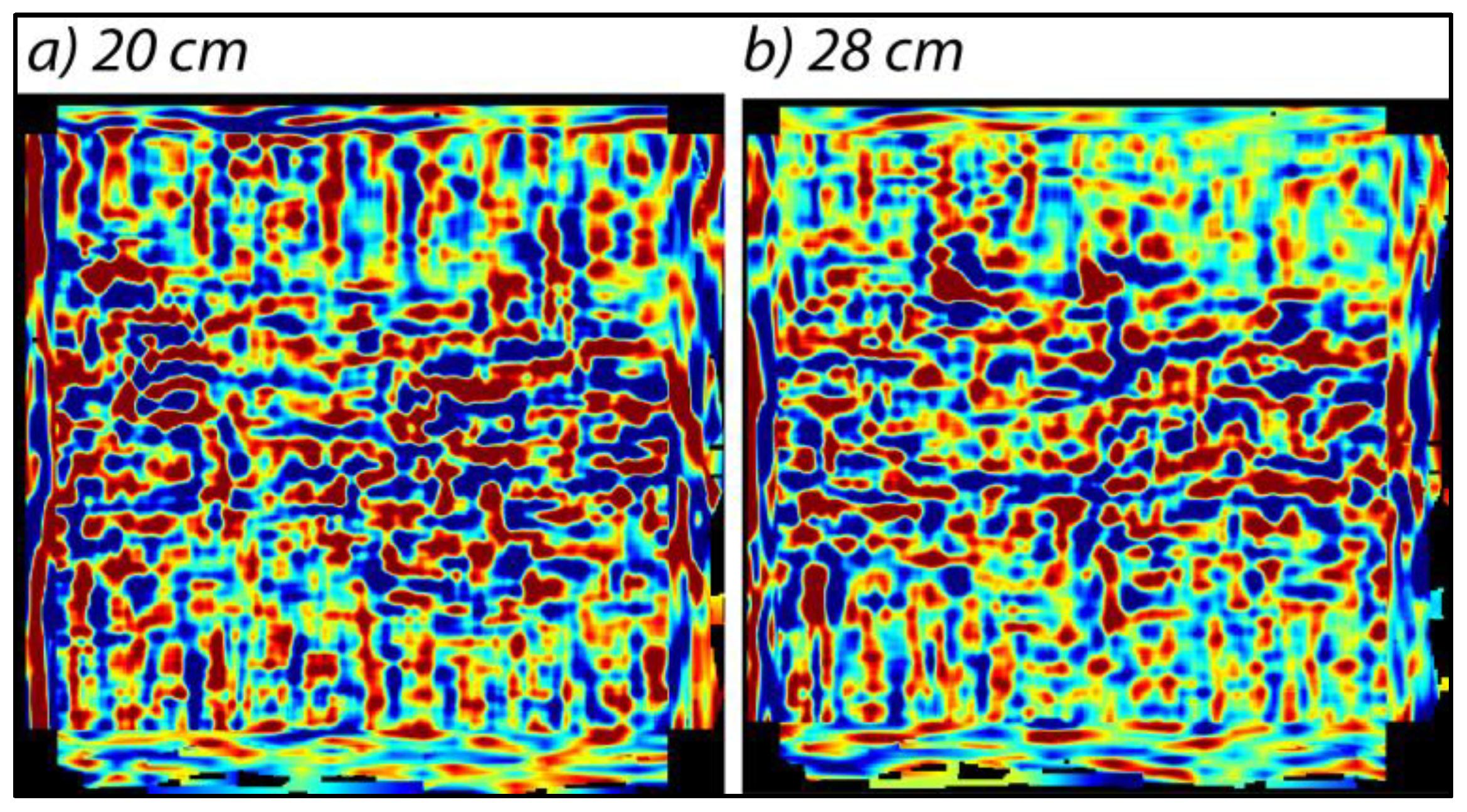
Figure 8.
a) Location of the corbels’ clamping identified. b) Radargram n.4 that shows the compact wall structure of the western side of the Tower with an evident horizontal stratification in the first 100-150 cm (highlighted in green) and some reflections (in red), positioned around 1.5 m deep, in correspondence with the vaults supporting the walkway. c) Radargram of scanline n.5 (elaboration E. Marchetti).
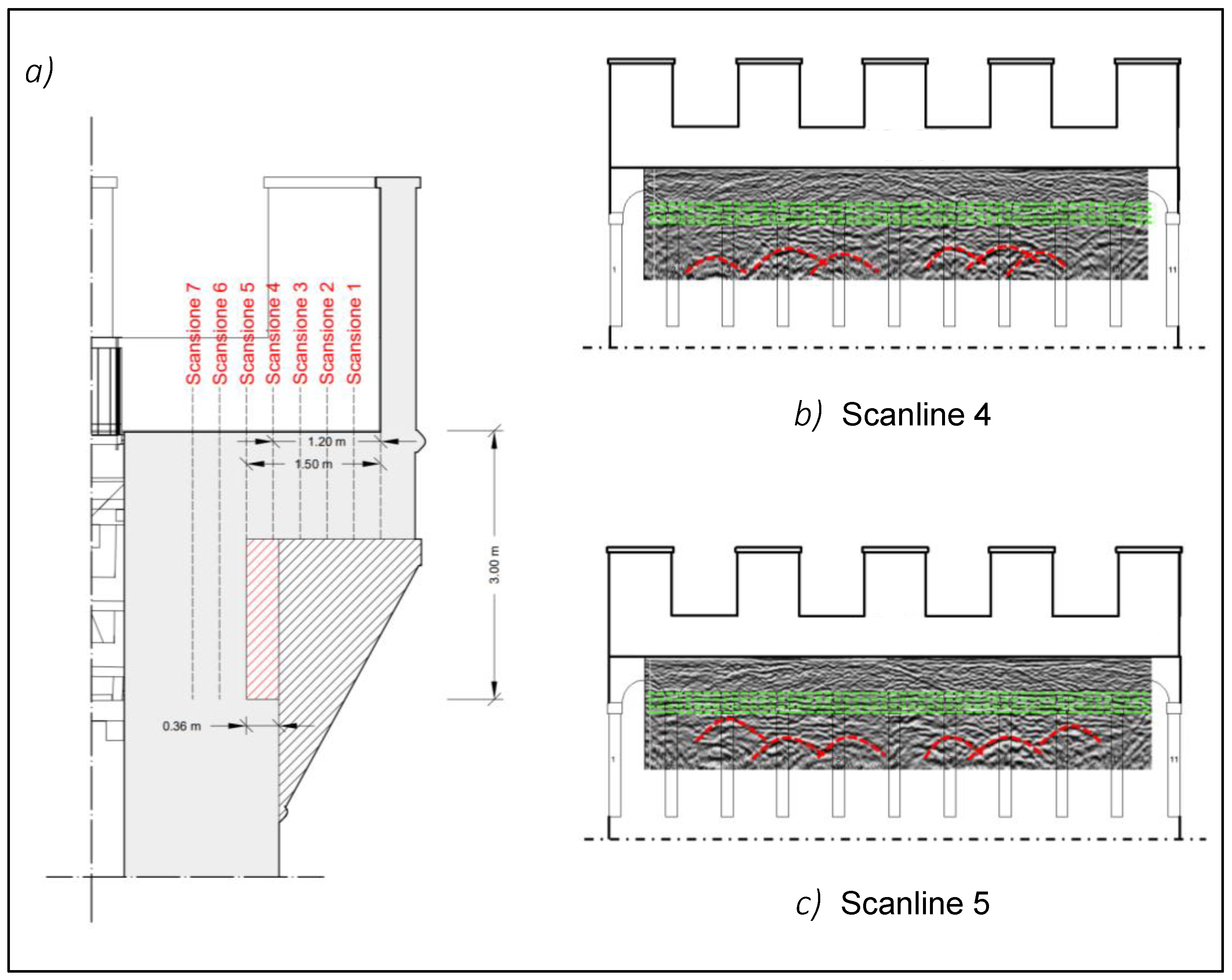
Figure 9.
a) Corbel setting, b) example of the sonic velocity detected for the corbel n.1, in red the position of the grates (elaboration M. Coli).
Figure 9.
a) Corbel setting, b) example of the sonic velocity detected for the corbel n.1, in red the position of the grates (elaboration M. Coli).
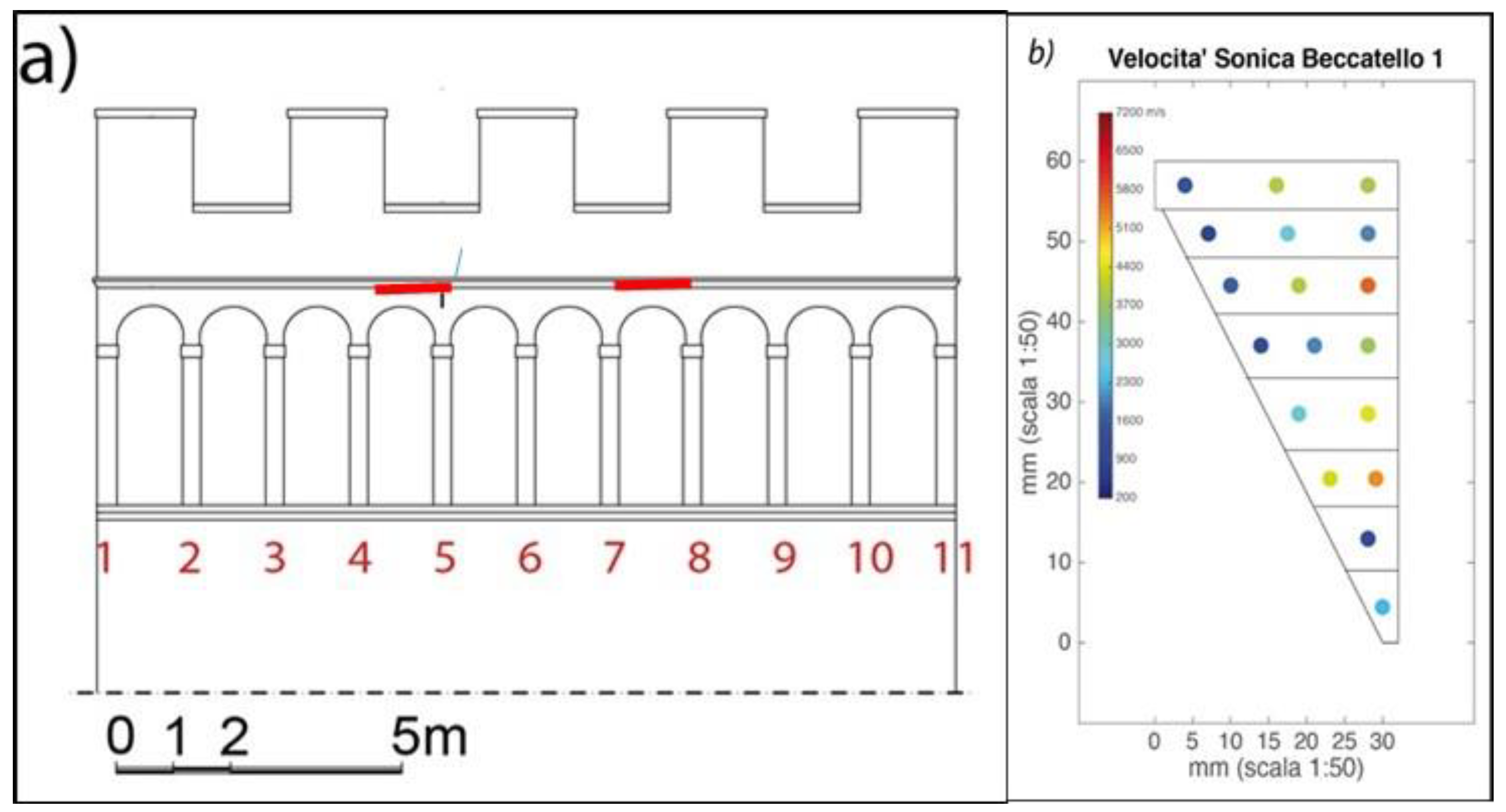
Figure 10.
View of the Tower of San Niccolò in the XVII century (by Livio Mehus) in which the rock stratifications of Pietraforte on the banks of the Arno acting as foundation of the Tower are evident.
Figure 10.
View of the Tower of San Niccolò in the XVII century (by Livio Mehus) in which the rock stratifications of Pietraforte on the banks of the Arno acting as foundation of the Tower are evident.
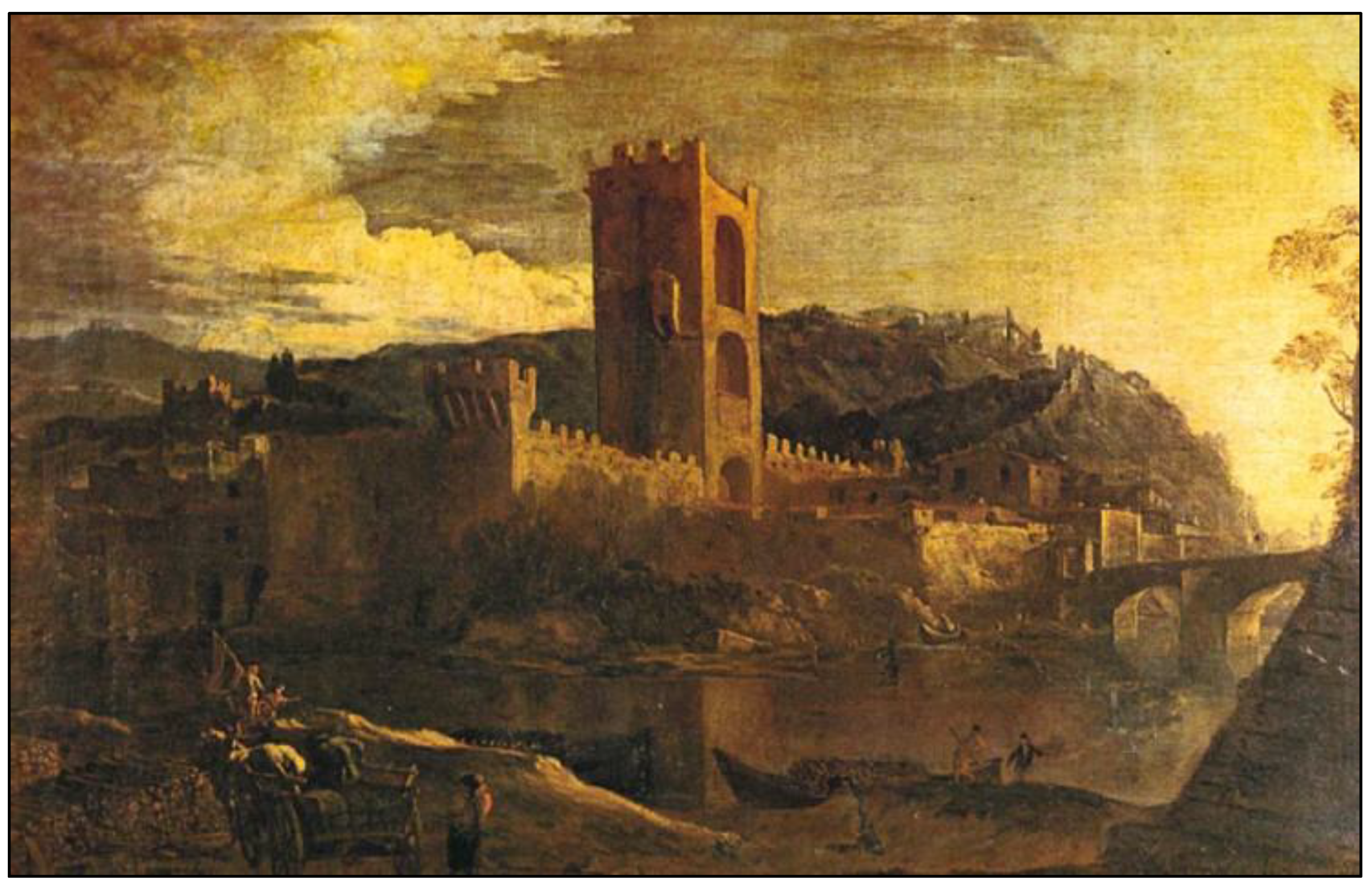
Figure 11.
Geological section of the area of the Torre di San Niccolò, also showing the reservoir for the Rampe waterfalls, the sewers and the structures of the old Water Factory.
Figure 11.
Geological section of the area of the Torre di San Niccolò, also showing the reservoir for the Rampe waterfalls, the sewers and the structures of the old Water Factory.
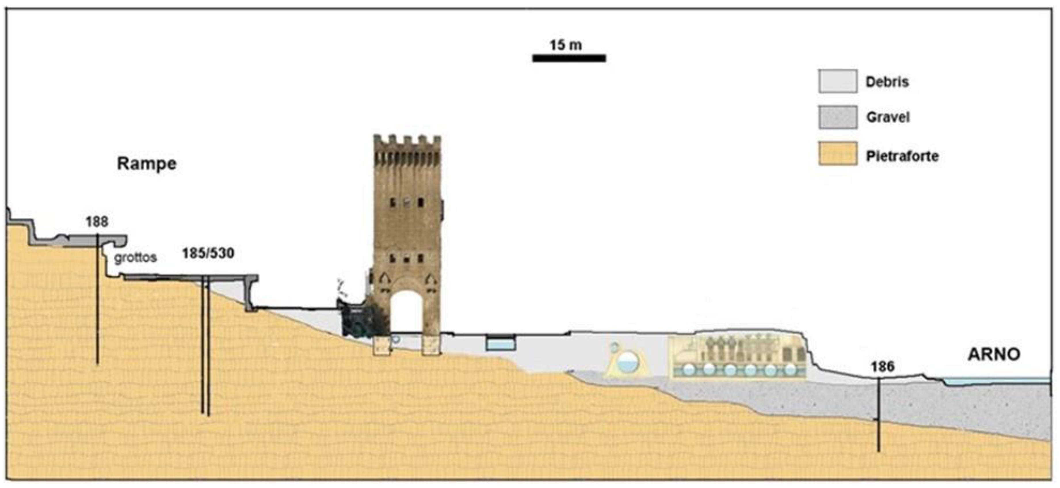
Figure 12.
Left: Set of the 7 accelerograms used for a return period of 712 years. Right: Elastic response spectra of the 7 accelerograms (blue) compared with the Italian elastic spectrum for foundation on rock (red); the structural period band of the San Niccolò Tower’ is shown in grey.
Figure 12.
Left: Set of the 7 accelerograms used for a return period of 712 years. Right: Elastic response spectra of the 7 accelerograms (blue) compared with the Italian elastic spectrum for foundation on rock (red); the structural period band of the San Niccolò Tower’ is shown in grey.
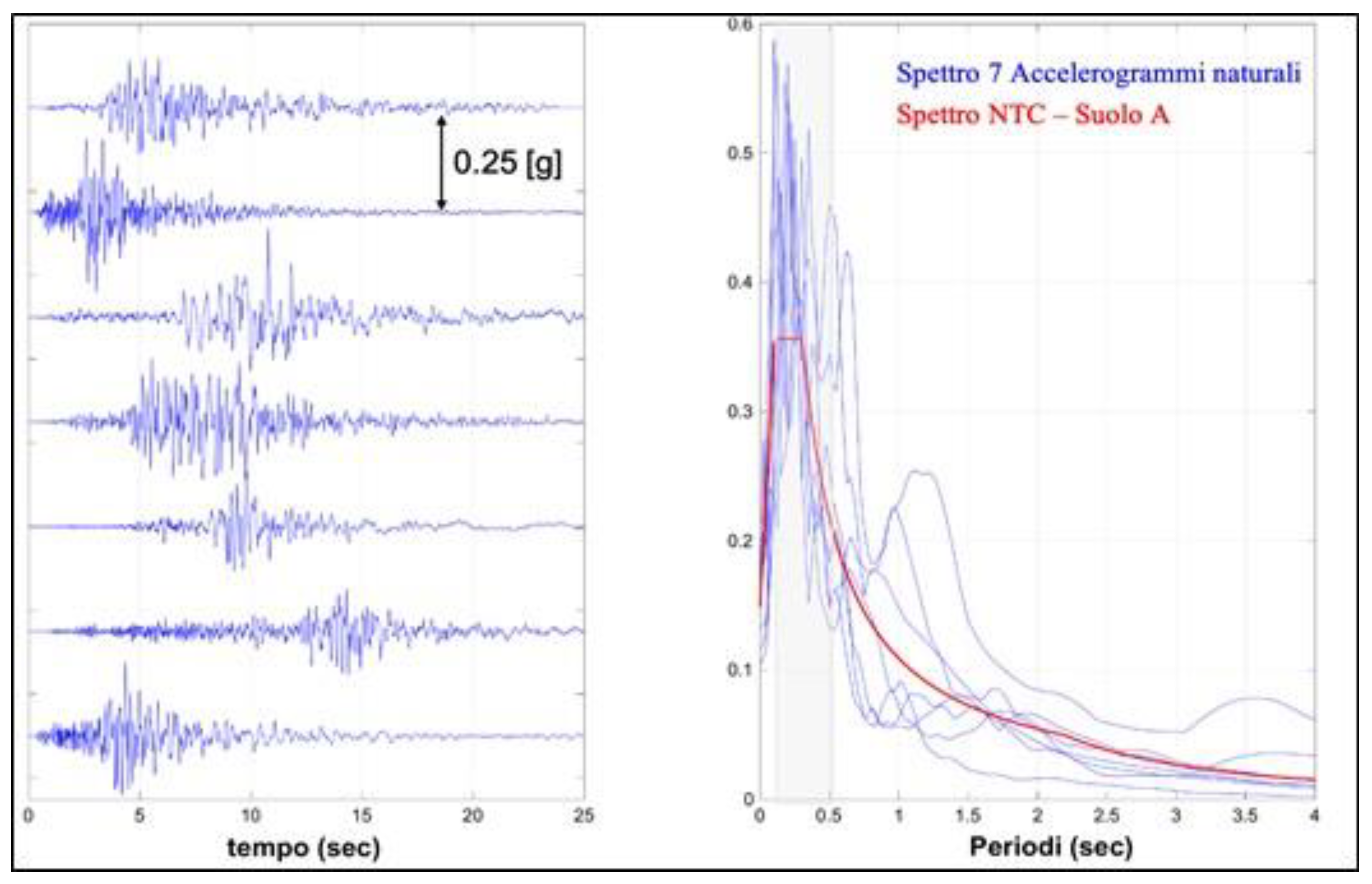
Figure 13.
Location of the 13 seismic stations installed on the Tower of San Niccolò, of which one sensor was placed at the base and 4 stations on each of the three levels.
Figure 13.
Location of the 13 seismic stations installed on the Tower of San Niccolò, of which one sensor was placed at the base and 4 stations on each of the three levels.
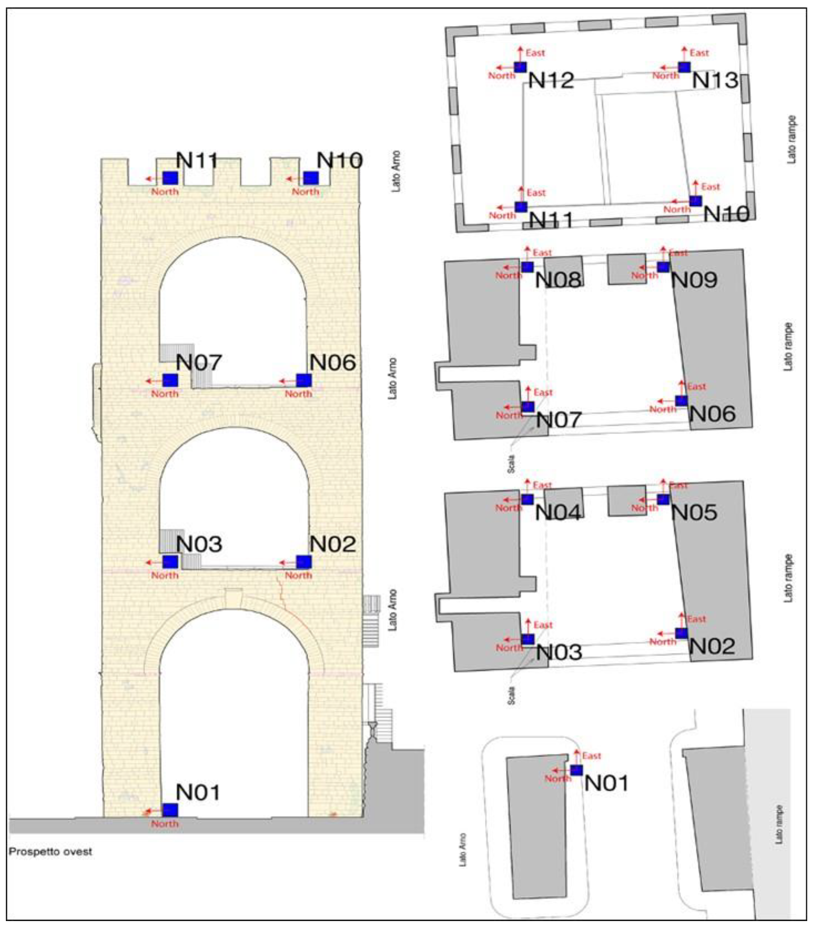
Figure 14.
Three-dimensional representation of the 5 modal deformations identified for the Tower of San Niccolò.
Figure 14.
Three-dimensional representation of the 5 modal deformations identified for the Tower of San Niccolò.
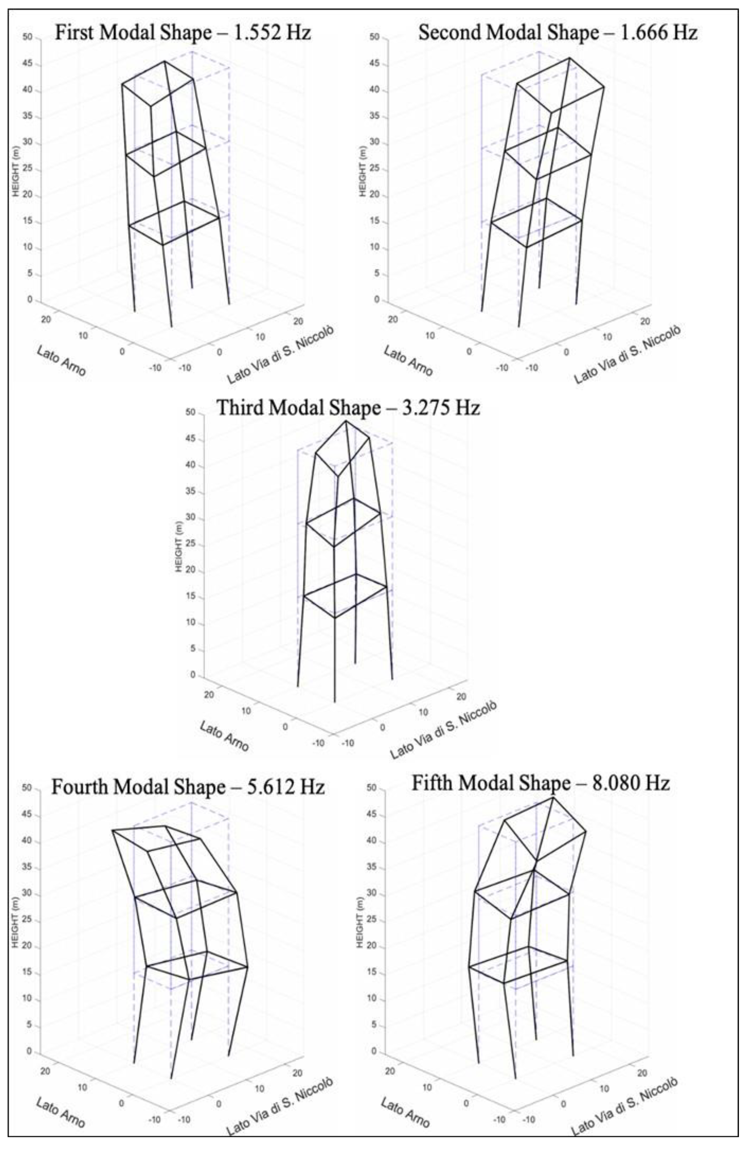
Figure 15.
Ratio between Vp and R for Pietra Serena beams of the corbels to verify the level of surface degradation.
Figure 15.
Ratio between Vp and R for Pietra Serena beams of the corbels to verify the level of surface degradation.
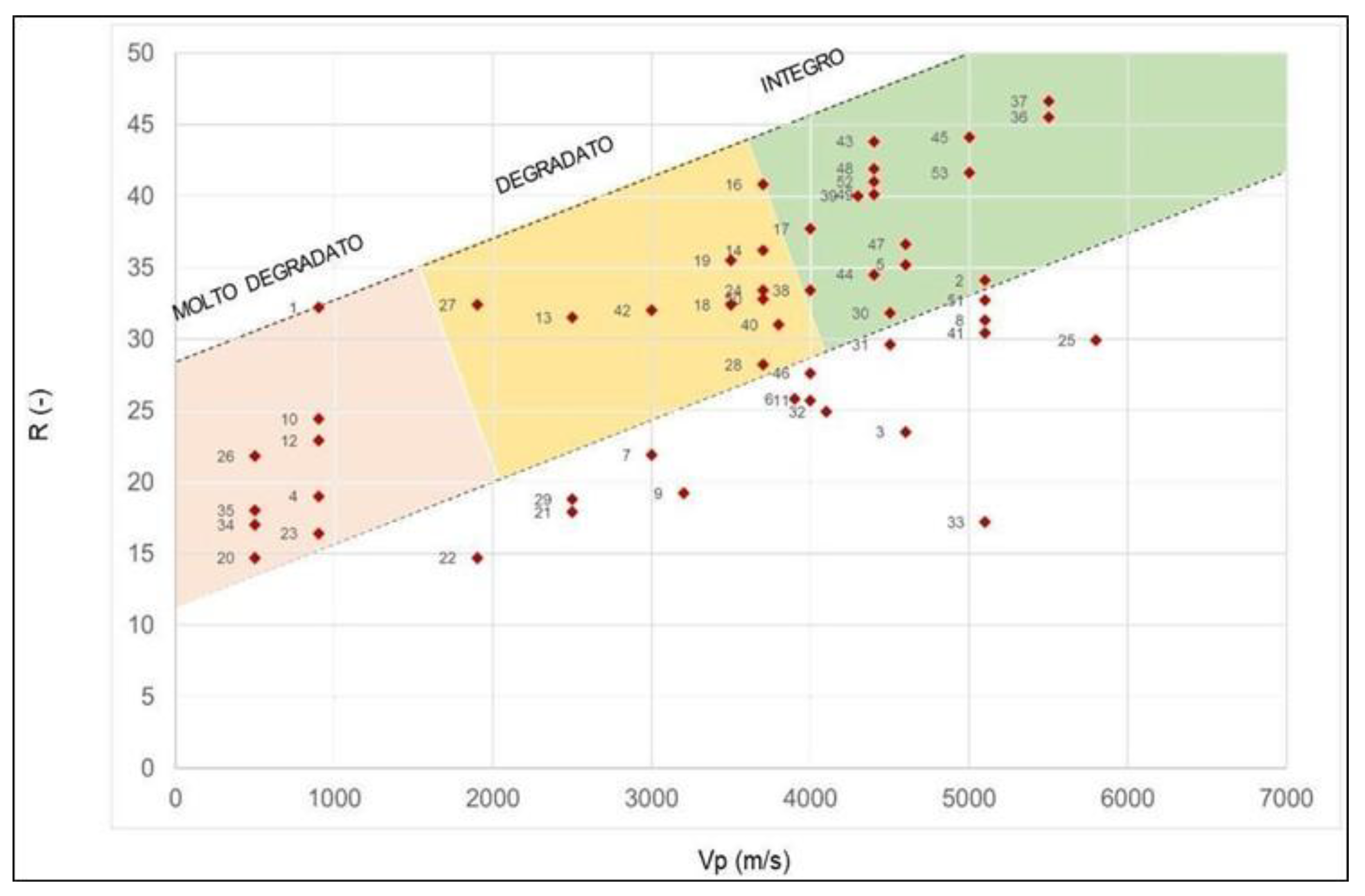

Table 1.
Classification of the San Niccolò’ Tower-Gate masonry according to different approaches.
| Classification | Type |
| Historic Tuscan masonry [8] | “Stonemason techniques with quarry quoins placed in horizontal courses”; an advanced typology in use since the XII century and linked to the supply of stone materials from newly opened quarries |
| National Department of Civil Protection [11] | Type A2 “Rough stone masonry”, but with exposed facades of Type A5 “Squared stone masonry |
| Tuscany Region’s Masonry Abacus [12] | Type C “Rough-hewn stone masonry with irregularities”, formerly Type II of Ministerial Circular 617/2009 [ ], falling into Class AoDMbD |
| Circular no. 7 of January 21, 2019 [13] | To Table C8.5.I as Class III “Good-textured split stone masonry”. This table also provides the reference parameters to be used in seismic assessments. Table C8.5.II, reports the correction values for the physical-mechanical parameters based on the state of conservation of the masonry, for the San Niccolò’ Tower-Gate an overall correction factor of 2.4 is applicable. |
Disclaimer/Publisher’s Note: The statements, opinions and data contained in all publications are solely those of the individual author(s) and contributor(s) and not of MDPI and/or the editor(s). MDPI and/or the editor(s) disclaim responsibility for any injury to people or property resulting from any ideas, methods, instructions or products referred to in the content. |
© 2025 by the authors. Licensee MDPI, Basel, Switzerland. This article is an open access article distributed under the terms and conditions of the Creative Commons Attribution (CC BY) license (http://creativecommons.org/licenses/by/4.0/).
Copyright: This open access article is published under a Creative Commons CC BY 4.0 license, which permit the free download, distribution, and reuse, provided that the author and preprint are cited in any reuse.


