Submitted:
04 October 2025
Posted:
06 October 2025
You are already at the latest version
Abstract
In this study, core–shell structured B@NiF₂/AP composite micro-units with varying mass ratios were prepared using planetary ball milling technology to optimize the energy release and combustion performance of boron (B) powder. The optimal formulation was determined to be 0.5% NiF₂, 13.3% B, and 86.2% AP. Morphological characterization revealed that NiF₂ was uniformly coated on the surface of B particles, forming a dense shell structure that significantly enhanced the moisture resistance and oxidation stability of boron. Thermal behavior analysis indicated that the NiF₂ interfacial layer, due to its high-temperature fluorination reaction (NiF₂ → Ni + 2F), released highly electronegative fluoride ions that reacted with the B₂O₃ film on the boron surface, generating boron oxyfluoride gas and forming void structures. Experimental results showed that the composite material achieved a maximum heat release of 8912 J/g, at least 6.5% higher than other samples, and a mass gain of up to 74.58%, indicating a more complete reaction. Additionally, the oxygen released from AP decomposition further promoted combustion. Ignition and combustion analysis demonstrated a minimum ignition delay of 0.618 s—over 0.04 s shorter than that of other samples—and the lowest ignition energy at 22.17 J. The ignition flame exhibited a well-defined and complete profile with significantly enhanced combustion intensity. Overall, the core–shell structured B@NiF₂/AP composite micro-units provide a novel solution for the application of boron fuel in solid propellants and pyrotechnic technologies.
Keywords:
boron
; surface coating
; ignition performance
; combustion rate
; core–shell composite structure
1. Introduction
Solid propellants serve as the power source for missiles, spacecraft launch vehicles, and rocket engines. (Badgujar et al. 2008; Shalini and Dave 2019; Zhang et al. 2009) With the advancement and development of military science and aerospace technology, the demand for high-energy development of solid propellants has been continuously increasing. Currently, the composition of propellants primarily includes: fuel, oxidizer, binder, and various additives (Lysien et al. 2021; Salgado et al. 2018). One of the main research directions for meeting the demand for high-energy development is to enhance the more efficient energy release from the fuel.
In the field of aerospace propellants and high-energy fuels, boron powder (B) has received sustained attention due to its unique combustion characteristics (E-Xiu et al. ; Hu et al. 2024; Liu et al. 2017; Wang et al. 2022; Xu et al. 2008; Zhang et al. 2022; ).As the non-metallic element with the highest calorific value (58.28 MJ/kg), the combustion heat of boron is 1.9 times that of aluminum (Eslami, Hosseini and Pourmortazavi 2008), and theoretically, it can produce an adiabatic flame temperature exceeding 3200 K. This characteristic makes it an ideal candidate material for solid rocket propellants and energetic additives in scramjet engines. However, the practical application of boron has long been limited by its complex combustion mechanism. When boron particles come into contact with air at room temperature, they form a dense, amorphous B2O3 oxide layer (Chintersingh et al.2019; Hastings et al.2022; Lebedeva et al.2022). This passivation layer, with a thickness of about 3-5 nm, melts at 600-800 ℃ to form a glassy encapsulating layer, which hinders the diffusion of oxygen inward, resulting in an ignition delay time of several tens of milliseconds.
Experiments have shown that boron powder with a diameter of 10 μm requires an environmental temperature exceeding 1900 K under standard atmospheric pressure to sustain combustion, which is significantly higher than the operating temperature of conventional propellants. The liquid oxide layer formed during combustion can also lead to particle agglomeration (Gao et al. 2007; Singh et al. 2004), reducing combustion efficiency and resulting in actual energy release only reaching 40%-60% of the theoretical value.
According to previous literature, surface coating technologies can improve the ignition and combustion performance of metal fuels (Deng et al. 2018; Guo et al. 2012; He et al. 2020; Ma et al. 2020; Tang et al. 2020; Zhu et al. 2017). Metals (Weismiller et al. 2018), metal anhydrides or oxides (Lee et al. 2019; Yuan et al. 2010), rare earth metal catalysts (Cheng et al. 2020), and fluorine-containing materials (Young et al. 2013) have been used to coat boron particles. Relevant studies have shown (Matsumoto et al. 2003; Glotov et al. 2023) that fluorides significantly improve the ignition and combustion of boron powder. They can react with the B2O3 oxide layer on the surface of boron particles, exposing the boron surface, thus accelerating the ignition of boron particles. The heat released during ignition further accelerates the reaction between the fluoride and the boron surface oxide. At the same time, the energy released from the formation of boron fluoride compounds by fluorine (F) and boron (B) per unit mass is much higher than the energy released from the formation of B2O3 by oxygen and boron powder, which greatly benefits overall energy enhancement.
By coating the surface with lithium fluoride or combining with magnesium-aluminum alloys, the ignition temperature can be reduced to below 1600 K. X-ray diffraction analysis shows that this treatment disrupts the continuity of the oxide layer. Synchrotron radiation diagnostic technology confirmed that the residence time of the modified boron powder in supersonic airflow is reduced to 2 ms, and the combustion efficiency is improved to over 85%. Test data released by Keerthi et al. (2022) in 2022 shows that composite propellants containing 30% nano-boron achieve a specific impulse of 280 s, a 15% improvement over traditional formulations, marking a substantial advancement in the engineering application of boron-based fuels.
Metastable intermolecular composites (MICs) are typically composed of metal fuels and oxidizers. The ignition and combustion performance of various preparation procedures as well as different MIC reaction systems were compared and discussed by He et al. (2018) In particular, the advantages of the new structure MIC in terms of safety and combustion efficiency were elucidated. Boron, in some respects, is similar to aluminum, and the oxidizers for boron-based MICs are typically halates (ammonium perchlorate, potassium perchlorate, etc.), polyether compounds (polyazide glycidyl ether, 3,3-bis (azidomethyl)oxirane-tetrahydrofuran copolyether, etc.), and halogen-containing environments. Ulas et al. (2001) studied the ignition and combustion of isolated boron particles in fluorine-containing environments from both experimental and theoretical perspectives. The experimental data revealed that hydrogen fluoride (HF) increases the total combustion time of boron particles, while fluorine (F) significantly reduces the total combustion time. Theoretical model simulations of the combustion of isolated boron particles in fluorine-containing environments showed that the simulated results were consistent with the experimental data.
Xie et al. (2014) studied the combustion performance of boron coated with ammonium perchlorate (AP). AP/B composite particles were prepared using a solvent evaporation method, and the experimental results showed that the combustion characteristics of AP/B composite particles were significantly improved compared to traditional boron particles, with the light intensity instantly approaching its maximum value. The explosive heat of DNTF explosives containing AP/B composite particles (7696 kJ/kg) was 6.5% higher than that of uncoated explosives (7208 kJ/kg), indicating that coating technology can effectively enhance the energy release. Wei et al. (2003) investigated the rheological properties of propellant slurries in experimental formulations of fuel-rich propellants containing up to 30% boron, using boron powder coated with four different amounts of AP. The results showed that the optimal coating amount of 20% AP, along with a well-coated surface and nearly spherical particle shape, resulted in the best rheological properties for the slurry. Cheng et al. (2021) prepared B/Mg, B/Al, B/Ni, B/Fe, and B/Mo composites using ball milling. Thermal analysis of Fe and Mo-doped boron powder indicated that boron powder has good reactivity and performance. Liu et al. (2024) coated boron powder with halogenated compounds for high combustion efficiency and prepared four types of micro-nano B-Fe-Bi2O3@AP/PVDF composites. The highest combustion temperatures of these composites reached 1954-2011 ℃, and the combustion efficiency was greatly improved in various atmospheres.
Based on the high calorific value of boron and the strong oxidizing ability of ammonium perchlorate, this study proposes a novel core-shell structure B@NiF2/AP composite micro-unit design, aiming to break through the bottleneck of the oxide layer barrier in traditional boron-based fuels and the energy release efficiency of AP-based propellants. By introducing a nickel fluoride (NiF2) interfacial layer, which utilizes its high-temperature fluorination reaction properties (NiF2 → Ni + 2F), the B2O3 passivation layer is directionally destroyed and fluorine radicals are released. This simultaneously enhances the ignition and accelerates the combustion of boron particles. Meanwhile, AP, as the oxidizer shell, is coated, and through the nanoscale intimate contact between the oxidizer and fuel inside the micro-unit, the oxygen transfer path is shortened, reducing the diffusion combustion lag effect. This multi-scale synergistic strategy greatly improves the combustion efficiency of boron. This study constructs the core-shell micro-unit structure using a planetary ball milling process, combined with thermodynamic testing and ignition combustion analysis, revealing the coupling mechanism of fluorination interfacial reaction kinetics and energy release, providing theoretical support and material paradigms for the design of the next generation of high-energy, low-signature solid propellants.
2. Experimental Section
2.1. Experimental Materials
Amorphous boron powder (amorphous B powder, D50 = 2.731 μm) was provided by the Hubei Aerospace Chemical Technology Research Institute. Ammonium perchlorate (AP, NH₄ClO₄, D50 = 188.351 μm) was purchased from Dalian Northern Potassium Perchlorate Factory. Nickel fluoride (NiF2, D50 = 3.462 μm) was purchased from Nanjing Chemical Reagent Co., Ltd.
2.2. Preparation Process of B@NiF2/AP Composite Micro-Units
The samples were prepared using a planetary ball milling method. First, 1.0000 g of amorphous boron powder was accurately weighed using an electronic balance with a precision of 0.0001 g, and the corresponding amounts of NiF2 (2%, 4%, 8%, 12%, and 16% by weight) were precisely weighed. The weighed amorphous boron powder and NiF2 were placed in a 100 mL ball milling jar and subjected to ball milling using a QM-2SP4 planetary ball mill. To control experimental variables, all samples underwent the same ball milling procedure, with a set speed of 300 rpm, ensuring the independent investigation of the effect of different NiF2 doping levels on the performance of boron powder. After milling, the samples were sieved through a 90-mesh screen and divided into portions for subsequent performance characterization.
Subsequently, based on the oxygen balance theory (Abbas, Riggins and Watson 2020; Matsunaga and Huba 2014), the B@NiF2 core-shell structure with a 4% NiF2 doping level was selected and combined with ammonium perchlorate (AP) at different ratio formulations (5:1, 6:1, 6.6:1, 8:1, and 9:1). The B@NiF2 core-shell structure and AP were accurately weighed using an electronic balance with a precision of 0.0001 g and placed in a mortar for grinding until a uniform mixture was obtained. The ground samples were then sieved through a 90-mesh screen and divided into portions, preparing them for subsequent performance testing.
2.3. Sample Characterization
The morphology of the composite micro-units was observed and recorded using a Hitachi Regulus 8100 scanning electron microscope (SEM) produced by Hitachi. During the test, a small amount of powder sample was uniformly dispersed on conductive tape, and the sample was gold-coated for 45 seconds under a current of 10 mA using an Oxford Ultim Max 65 sputter coater to enhance its conductivity. The test conditions were set as follows: acceleration voltage of 3 kV, and for energy spectrum mapping, the acceleration voltage was set to 20 kV. The SE2 secondary electron detector was used to obtain high-resolution images at different magnifications.
The surface structure, elemental valence states, and content of the composite micro-units were semi-quantitatively analyzed using a Thermo Scientific K-Alpha X-ray photoelectron spectrometer (XPS). The tests were conducted using Al Kα radiation (hv = 1486.6 eV), with a working voltage of 12 kV and filament current of 6 mA.
To investigate the thermal behavior of the samples, a TA Instruments SDT 650 thermogravimetric-differential scanning calorimeter (TG-DSC) was used to characterize the thermal and kinetic properties of the samples. Approximately 1.5 mg of the sample was tested in an air atmosphere at a gas flow rate of 50 mL/min. The sample was placed in an alumina crucible and heated at a rate of 20 ℃/min from 50 ℃ to 1200 ℃. Prior to testing, the thermal analyzer was mass-calibrated using standard mass weights (with a sensitivity of 0.1 μg for the thermal balance) and calibrated for heat flow using sapphire. The raw data were processed and analyzed using Universal Analysis 2000 software.
To further investigate the heat release properties of the samples, an IKA C3000 isoperibol calorimeter, produced by IKA Works GmbH & Co., was used to measure the combustion heat of the samples. Based on the measurable energy range of the calorimeter, approximately 300 mg of the sample was tested in a high-concentration oxygen atmosphere. The sample was ignited using a platinum wire and ignition cotton wick, and combustion occurred within a sealed bomb calorimeter. The cotton wick had a heat value of 50 J/g.
For the ignition and combustion performance of the samples, a custom-built combustion testing system was used, which has been previously reported in earlier articles (Ke et al. 2018; Mao et al. 2023) and is shown in Figure 1. First, 30 mg of the sample was placed on the ignition platform, and a 0.25 mm nichrome wire was passed through the sample and wound onto the ignition electrode. The sample was rapidly heated and ignited with a constant pressure power supply (15 V). During this process, a TELEDYNE WAVESURGER3054 oscilloscope received optical signals from a light sensor (Thorlabs DETO2AFC) and electrical signals transmitted from the ignition electrode. The current, pressure, and light signals generated by the sample combustion were displayed on the oscilloscope. The minimum energy required for ignition was calculated using the ignition energy formula, as shown in equation 1. The ignition delay time, denoted as t (s), was defined as the time required from the generation of current to the sudden increase in the optical signal. The DC voltage applied to the circuit was U (V), and the current in the circuit was I (A). Typical voltage, current, light signals, and ignition delay time for open ignition combustion tests were recorded. Each sample was tested 3-5 times, and the average value of three data sets with a standard deviation between 0 and 0.5 was retained.

At the same time, a high-speed camera system from PHOTRON, Japan, the Photron UX100, along with data acquisition and analysis software, was used to capture the flame characteristics and ignition performance of the sample. The recording speed was set to 2000 fps.
3. Results and Discussion
3.1. Morphology and Structure
The morphology of the B@NiF2 composite materials at different ratios and the raw B material was observed using the planetary ball milling technique. The test results are shown in Figure 2.
Figure 2f shows the SEM image of the raw B powder. Figure 2a indicates that when the NiF2 content is insufficient, the product exhibits significant inhomogeneity: the surface of the boron particles is incompletely coated, with obvious exposed areas, and there are gaps at the interface between boron powder and NiF2. This structural defect leads to the scattering of a large number of unbound particles on the surface.
Figure 2b–d show a significant improvement in the morphology of the product: the coating is complete with no scattered particles, forming a regular core-shell structure with particle sizes ranging from 500 nm to 2 μm. This structural feature is favorable for the formation of a dense protective layer.
Although Figure 2e achieves complete coating of the boron powder, excess NiF2 secondary particles are attached to the surface. The shell thickness increases significantly, with the overall diameter ranging between 3 and 4 µm. This prevents the micro-nano materials’ small size and rapid energy release from being fully utilized. Additionally, the excessive shell thickness negatively impacts the stability of the subsequent B@NiF2/AP composite micro-unit structure formed with the added oxidizer AP.
From Figure 3 and Figure 4, it can be seen that as the NiF2 content increases, the B-B bond content in the sample shows a trend of first increasing and then decreasing. Additionally, the B2O3 content also shows significant changes at different NiF2 doping levels, with noticeable fluctuations in the impurity Bx-O bond content. This indicates that the incorporation of NiF2 affects the surface oxidation of the boron powder.
With NiF2 contents of 2%, 4%, 8%, 12%, and 16%, the Bx-O content gradually increased from 31.9% at 2% doping to a maximum of 59.7% at 12%, indicating that excessive NiF2 doping accelerates the hybridization reaction of boron powder. At different doping levels, the B2O3 content was relatively low at 2% doping (8.4%), and as the doping amount increased, the B2O3 content at 4% NiF2 doping remained low at 8.5%, before showing an increasing trend. This suggests that the NiF2 coating reduced the oxidation of the boron powder to some extent. The B-B bond content gradually decreased with increasing NiF2, indicating that NiF2 promotes the oxidation of boron powder to some extent.
Comparing the different samples, the areas of the fitted peaks for each bond type were compared. For the composite micro-unit at 4% NiF2, the B2O3 content on the surface was lower, at 8.5%, and the characteristic peak area for elemental B-B reached the highest level at 60.0%. This shows that among the five samples, the 4% NiF2 content had the best effect in isolating the oxidation of boron powder. During the collision and extrusion process, active boron was exposed to oxidation, and the appropriate exposed area allowed it to effectively embed in the NiF2 particles, leading to a uniform mixture.
Figure 5 shows that the different NiF2 formulation ratios have little effect on the peak shape, but they significantly influence the peak area and peak height. As the NiF2 ratio increases, the corresponding peak area and peak height for NiF2 also increase. The peak shapes for all the samples are consistent. When compared to the standard reference card, it can be observed that the peak shapes for all the substances match those of the standard material, indicating that the surface of the entire material is uniformly mixed and coated, forming a complete B@NiF2 composite micro-unit.
3.2. Thermal Behavior Analysis of B@NiF2
The DSC curves for different NiF2 doping levels are similar. Under an air atmosphere, all the ball-milled samples show a heat-induced weight gain exothermic peak between 610°C and 680°C. However, with increasing NiF2 content, the exothermic peak shifts to an earlier temperature. From the TG curve, it can be observed that the sample weight decreases with increasing temperature before 560°C. According to the literature, the continuous weight loss between 300°C and 560°C is attributed to the decomposition of NiF2. After 560°C, the weight gain corresponds to the oxidation-reduction reaction between boron and oxygen, forming B2O3 and releasing a large amount of heat, which is represented by the exothermic peak in Figure 6.
As shown in Table 1, the exothermic peak temperatures of the samples under different NiF2 doping levels are generally consistent. However, when the NiF2 doping level is 4%, the exothermic energy of the sample reaches the maximum value of 8912 J/g, which is more than 7% higher than that of the samples with other doping ratios. At the same time, the oxidation weight gain rate of this sample also reaches the highest value of 74.6%, which is more than 9.0% higher than that of the other samples. This result indicates that the introduction of NiF2 significantly enhances the heat release of the boron powder and increases its degree of reaction. Among the five groups of samples, the 4% NiF2 doping level optimizes both the heat release performance and the degree of reaction of the sample.
The data from the bomb calorimeter in Table 2 also show that the heat release varies with different NiF2 doping levels. When the NiF2 doping content is 4%, the sample reaches the maximum heat release of 14657 J/g, which is significantly higher than the heat release of the samples with other doping levels.
Based on the performance results of the BN samples, the most suitable B@NiF2 sample, BN-2, was selected. After determining the appropriate ratio, the oxidizer AP was added according to the steps mentioned above to prepare the ternary B@NiF2/AP composite micro-unit structure (BNA sample). The thermal properties and ignition combustion performance of the BNA sample were then characterized and analyzed.
3.3. Thermal Behavior Analysis of B@NiF2/AP
To investigate the effect of different ammonium perchlorate (AP) doping levels on the thermal performance of B@NiF2, differential scanning calorimetry-thermogravimetric analysis (DSC-TG) was used for thermal characterization. The experimental results are shown in Figure 7. The DSC curves under different AP doping levels exhibit similar characteristics. When heated in an air atmosphere, all the samples show a small endothermic peak around 250°C, accompanied by a slight weight loss, which is attributed to the endothermic decomposition of AP. Subsequently, around 380°C, a significant exothermic reaction occurs, accompanied by a sharp weight loss, indicating that the sample undergoes a vigorous exothermic reaction and generates a large amount of gas. Finally, around 770°C, all samples exhibit a pronounced exothermic peak along with a significant weight gain. This phenomenon corresponds to the oxidation reaction of the boron powder and the associated exothermic process.
From the data in Table 3 and Figure 7a,b, it can be seen that samples with different AP doping levels exhibit similar reaction temperatures. When the stoichiometric ratio of AP to B@NiF2 is 6.5:1, the sample’s heat release reaches the maximum value of 635 J/g, which is more than 1.9% higher than that of the other samples. The weight change, as an indicator of the degree of reaction, shows minimal differences between the five groups of samples. Considering the data from the heat release, reaction temperature, and weight change, the sample with a stoichiometric ratio of 6.5:1 shows the best thermal performance. The experimental results indicate that the addition of AP as an oxidizer significantly improved the thermal performance of the B@NiF2 mixture, with the 6.5:1 stoichiometric ratio being the optimal doping ratio.
To further investigate the thermal performance of the AP-doped samples, the combustion heat release of the samples was measured using a bomb calorimeter.
From Table 4, it can be seen that as the AP doping level increases, the heat release of the samples decreases. When the stoichiometric ratio of AP to B@NiF2 is 6.5:1, the heat release decreases significantly.
3.4. Effect of AP Content on the Ignition and Combustion Performance of B/NiF2/ AP Modified Composite Micro-Units
From Figures 8a–f and combined with the data in Table 5, it can be observed that the incorporation of AP at different stoichiometric ratios has a significant impact on the ignition performance of B@NiF2. Among the samples, the 6.5:1 doping ratio shows a reduction in ignition delay time by at least 34 ms compared to the other groups, indicating that, based on the oxygen balance calculation, this AP doping ratio has the most significant improvement effect on the ignition delay. Although the samples with 8:1 and 9:1 doping ratios also exhibit good performance in terms of ignition light intensity signals, the 6.5:1 doping ratio samples not only have excellent ignition light intensity and lower ignition delay, but their combustion time is also significantly prolonged. This suggests that the combustion process of the sample at this ratio is more uniform and complete.
As shown in Figure 8f and Table 5, the ignition energy of the AP and B@NiF2 composite varies with the AP doping content, first decreasing and then increasing. At the 6.5:1 doping ratio, the ignition energy reaches its lowest value, indicating that the doping ratio based on oxygen balance calculations has a promoting effect on the combustion of the modified boron powder.
From Figure 9, the combustion behavior of the B@NiF2@AP core-shell structure at different AP:B@NiF2 ratios can be observed. Figures 9b,c show relatively clear and complete flame profiles at 121 ms and 310 ms, with a flame height of approximately 30 mm. However, in Figure 9c, the green edge around the flame is significantly less than in Figure 9b, indicating a relatively lower generation of the incomplete combustion product BO2. Additionally, Figure 9c shows a more complete and faster ignition and combustion process, with the flame intensity reaching its peak at 129 ms. This phenomenon suggests that at this ratio, the combustion process has a larger combustion area, stronger flame intensity, and shorter ignition and combustion times. Moreover, the reduced generation of incomplete combustion products, such as BO2, leads to more complete combustion, resulting in superior ignition and combustion performance.
3.5. Preliminary Exploration of the Reaction Mechanism of B/Metal Fluoride
In the combustion process, divalent metal fluoride NiF2 reacts with the surface oxide film (B2O3) on the boron (B) surface through its highly electronegative fluoride ions, generating boron oxyfluoride gas and forming a hole structure, as shown in reaction (2). Under combustion conditions, the reactivity of the fluoride ions is significantly enhanced, accelerating the reaction rate. The generated gas and holes progressively destroy the inert oxide layer structure on the boron surface, fully exposing the boron surface and effectively shortening the overall combustion time of the ignition phase. Additionally, the energy released from the reaction between fluorine (F) and boron (B) to form boron oxyfluoride compounds per unit mass is significantly higher than the energy released from the reaction between oxygen (O) and boron (B) to form boron oxide (B2O3) per unit mass. This characteristic not only significantly enhances energy release efficiency but also optimizes the energy release process by breaking down the boron powder’s surface oxide layer, thereby achieving higher combustion performance.
4. Conclusion
In this study, boron (B) powder was modified using ammonium perchlorate (AP) and nickel fluoride (NiF2), and a B@NiF2/AP composite micro-unit structure was designed and constructed. Based on the optimized binary B@NiF2 structure, the optimal mass ratio of AP to B@NiF2 was determined to be 6.5:1, corresponding to an overall formulation of 0.5% NiF2, 13.3% B, and 86.2% AP. During the ignition and combustion process, the NiF2 interfacial layer, through its high-temperature fluorination reaction (NiF2 → Ni + 2F·), releases highly electronegative fluoride ions that react to form boron oxyfluoride gas and create void structures, leading to full exposure of the boron surface. AP further enhances the etching and activation effect, thereby shortening the ignition phase and significantly improving the ignition and combustion performance of boron powder. The core-shell structured B@NiF2/AP composite micro-unit provides a novel solution for the application of boron fuel in solid propellants and pyrotechnics and establishes the optimal mass ratio for this ternary composite system.
Author Contributions
Yinhui Li, Jiaqi Cao and Changlin Zhu contributed equally to this work.
Notes
The authors declare no competing financial interest.
Acknowledgments
This research did not receive any specific grant from funding agencies in the public, commercial, or not-for-profit sectors.
References
- Abbas, M., D. Riggins, and M. D. Watson. 2020. Entropy-Based Performance Analysis of Chemical Rockets. AIAA SciTech 2020 Forum, Orlando, FL USA; pp. 22–43. [Google Scholar] [CrossRef]
- Badgujar, D. M., M. B. Talawar, S. N. Asthana, and P. P. Mahulikar. 2008. Advances in science and technology of modern energetic materials: An overview. Journal of Hazardous Materials 151, 2-3: 289–305. [Google Scholar] [CrossRef] [PubMed]
- Cheng, L., H. T. Yang, Y. Yang, Y. F. Li, Y. Y. Meng, Y. C. Li, D. M. Song, H. H. Chen, and A. Ramón. 2020. Preparation of B/Nitrocellulose/Fe particles and their effect on the performance of an ammonium perchlorate propellant. Combust. Flame 211: 456–464. [Google Scholar] [CrossRef]
- Cheng, L., H. T. Yang, M. A. Majeed, Y. F. Li, D. M. Song, and Y. C. Li. 2021. B/Metal composites' thermochemical properties and their effect on the performance of an ammonium perchlorate propellant. Journal of Energetic Materials 39, 3: 344–360. [Google Scholar] [CrossRef]
- Chintersingh, K. L., Y. L. Sun, M. Schoenitz, and E. L. Dreizin. 2019. Heterogeneous reaction kinetics for oxidation and combustion of boron. Thermochimica Acta 682: 178415. [Google Scholar] [CrossRef]
- Deng, S. L., Y. Jiang, S. D. Huang, X. J. Shi, J. H. Zhao, and X. L. Zheng. 2018. Tuning the morpho logical, ignition and combustion properties of micron-Al/CuO thermites through different synthesis approaches. Combust. Flame 195: 303–310. [Google Scholar] [CrossRef]
- E-Xiu, T. F., X. M. Zhi, Y. M. Zhang, C. X. Li, J. J. Zou, X. W. Zhang, and L. Wang. Jet fuel containing ligand-protecting energetic nanoparticles: A case study of boron in JP-10. Chemical Engineering Science 129: 9–13. [CrossRef]
- Eslami, A., S. G. Hosseini, and S. M. Pourmortazavi. 2008. Thermoanalytical investigation on some boron-fueled binary pyrotechnic systems. Fuel 87, 15: 3339–3343. [Google Scholar] [CrossRef]
- Gao, D. L., W. Zhang, H. Zhu, and Z. Z. Ji. 2007. Effect of Coating and Agglomerating on Combustion of Boron. Energetic Materials 15, 4: 378–381. [Google Scholar] [CrossRef]
- Glotov, O. G., V. A. Poryazov, G. S. Surodin, I. V. Sorokin, and D.A. Krainov. 2023. Combustion features of boron-based composite solid propellants. Acta. Astronautica 204: 11–24. [Google Scholar] [CrossRef]
- Guo, R., H. Yan, R. Q. Shen, Y. H. Hua, and L. Z. Wu. 2012. A micro initiator realized by integrating KNO3@CNTs nano-energetic materials with a Cu microbridge. Chemical Engineering Journal 211: 31–36. [Google Scholar] [CrossRef]
- Hastings, D., N. Rodriguez, H. McCann, M. Schoenitz, and E. L. Dreizin. 2022. Titanium-boron reactive composite powders with variable morphology prepared by arrested reactive milling. Fuel 310: 122313. [Google Scholar] [CrossRef]
- He, W., P. J. Liu, G. Q. He, M. Gozin, and Q. L. Yan. 2018. Highly Reactive Metastable Intermixed Composites (MICs): Preparation and Characterization. Advanced Materials 30, 41: 1706293. [Google Scholar] [CrossRef]
- He, W, Z. H. Li, S. W. Chen, G. C. Yang, Z. J. Yang, P. J. Liu, and Q. L. Yan. 2020. Energetic metastable n-Al@PVDF/EMOF composite nanofibers with improved combustion performances. Chemical Engineering Journal 383: 123146. [Google Scholar] [CrossRef]
- Hu, X. L., H. J. He, L. Y. Wang, C. H. Yang, X. X. Yao, W. L. Zhou, L. Q. Xiao, S. E. Liu, and J. F. Liu. 2024. The effect of compounding methods of binder on the thermal properties of boron powder. Journal of Ordnance Equipment Engineering 45, 1: 223–229. [Google Scholar] [CrossRef]
- Ke, X., S. F. Guo, G. S. Zhang, X. Zhou, L. Xiao, G. Z. Hao, N. Wang, and W. Jiang. 2018. Safe preparation, energetic performance and reaction mechanism of corrosion-resistant Al/PVDF nanocomposite films. Journal of Materials Chemistry A 6: 17713–17723. [Google Scholar] [CrossRef]
- Keerthi, V., H. Q. Nie, S. Pisharath, and H. H. Hng. 2020. Combustion Characteristics of Fluoropolymer Coated Boron Powders. Combustion Science and Technology 194, 6: 1183–1198. [Google Scholar] [CrossRef]
- Lebedeva, E. A., S. A. Astaf'eva, T. S. Istomina, and P. Badica. 2022. Combustion products agglomeration of propellant containing boron with fluorinated coatings. Combust. Flame 238: 111749. [Google Scholar] [CrossRef]
- Lee, H, P. R. Deshmukh, J. H. Kim, H. S. Hyun, Y. Sohn, and W. G. Shin. 2019. Spray drying for mation of metal oxide (TiO2 or SnO2) nanoparticle coated boron particles in the form of microspheres and their physicochemical properties. Journal of Alloys and Compounds 810: 151923. [Google Scholar] [CrossRef]
- Liu, C., H. J. Fan, Z. Y. Li, C. H. Guan, H. Li, and X. F. Qi. 2017. Combustion Characteristics of CMDB Propellant Containing Ball-boron Powder. Initiators & Pyrotechnics (3): 38–40. [Google Scholar] [CrossRef]
- Liu, J., D. Wang, Z. Zhang, and F. Li. 2024. Improvement of the Ignition Performance and Reaction Rate of Boron by Surface Modification. Combustion Explosion and Shock Waves 60, 1: 110–118. [Google Scholar] [CrossRef]
- Liu, R., D. F. Yang, Y. L. Zhang, H. Q. Nie, and Q. L. Yan. 2024. Preparation and Properties of Halogenated Oxidant Coated Modified Boron with High Combustion Efficiency. Chinese Journal of Energetic Materials 32, 10: 1068–1079. [Google Scholar] [CrossRef]
- Lysien, K., A. Stolarczyk, and T. Jarosz. 2021. Solid Propellant Formulations: A Review of Recent Progress and Utilized Components. Materials 14, 21: 1–17. [Google Scholar] [CrossRef] [PubMed]
- Ma, X. X., Y. X. Li, I. I. Hussain, R. Q. Shen, G. C. Yang, and K. L. Zhang. 2020. Coree-shell structured nano-energetic materials: Preparation and fundamental properties. Advanced Materials 32, 30: 2001291. [Google Scholar] [CrossRef] [PubMed]
- Mao, H. Q., X. Zhang, R. Cui, C. Z. Zhang, and X. Zhou. 2023. Preparation of Si@PVDF composite microspheres by electrostatic spraying for enhanced energetic characteristics. Combustion and Flame 252: 112740. [Google Scholar] [CrossRef]
- Matsumoto, K., Y. Itoh, and T. Kameda. 2003. EB-PVD process and thermal properties of hafnia-based thermal barrier coating. Science and Technology of Advanced Materials 4, 2: 153–158. [Google Scholar] [CrossRef]
- Matsunaga, H., H. Habu, and A. Miyake. 2014. Thermal decomposition of the high-performance oxidizer ammonium dinitramide under pressure. Journal of Thermal Analysis and Calorimetry 116: 1227–1232. [Google Scholar] [CrossRef]
- Salgado, M. C. V., M. C. N. Belderrain, and T. C. Devezas. 2018. Space propulsion: A survey study about current and future technologies. Journal of Aerospace Technology and Management 10: 1118–1123. [Google Scholar] [CrossRef]
- Shalini, C., and P. N. Dave. 2019. Solid Propellants: AP/HTPB Composite Propellants. Arab. J. Chem 12, 8: 2061–2068. [Google Scholar] [CrossRef]
- Singh, J, D. E. Wolfe, R. A. Miller, J. I. Eldrige, and D. M. Zhu. 2004. Tailored microstructure of zirconia and hafnia-based thermal barrier coatings with low thermal conductivity and high hemispherical reflectance by EB-PVD. Journal of Materials Science 39: 1975–1985. [Google Scholar] [CrossRef]
- Tang, D.Y., S. W. Chen, X. L. Liu, W. He, G. C. Yang, P. J. Liu, M. Gozin, and Q. L. Yan. 2020. Controlled reactivity of metastable n-Al@Bi (IO3)3 by employment of tea polyphenols as an interfacial layer. Chemical Engineering Journal 381: 122747. [Google Scholar] [CrossRef]
- Ulas, A., K. K. Kuo, and C. Gotzmer. 2001. Ignition and combustion of boron particles in fluorine-containing environments. Combustion and Flame 127, 1: 1935–1957. [Google Scholar] [CrossRef]
- Wang, F., X. B. Jiang, L. Ma, S. H. Ba, X. F. Wang, and Q. H. Mei. 2022. Study on Interface Modification of Boron Powder and Its Properties in Ignition Powder. Initiators & Pyrotechn ics (2): 39–42. [Google Scholar] [CrossRef]
- Wei, Q, B. X. Li, and H. Q. Tai. 2003. Effect of boron coated with AP on the rheological properties of slurry of fuel-rich propellant. Journal of Propulsion Technology 24, 5: 467–469. [Google Scholar] [CrossRef]
- Weismiller, M. R., Z. J. Huba, A. Epshteyn, and B. T. Fisher. 2018. Combustion of sonochemically-generated Ti-Al-B nano-powders in a premixed methane/air dust flame. Combust Flame 191: 187–194. [Google Scholar] [CrossRef]
- Xie, Z. Y., L. Zhou, H. Wang, K. Zhao, Y. M. Luo, and H. L. Zhang. 2014. Combustion Performance of Boron Coated with AP. Acta Armamentarii 35, 2: 194–199. [Google Scholar] [CrossRef]
- Xu, H. X., and F. Q. Zhao. 2008. Characteristics of high purity boron powder and its application in boron-based fuel-rich propellant. J Solid Rocket Technol (China) 31, 4: 368–373. [Google Scholar] [CrossRef]
- Young, G., C. A. Stoltz, D. H. Mayo, C. W. Robert, and C. L. Milby. 2013. Combustion behavior of solid fuels based on PTFE/boron mixtures. Combustion Science and Technology 185: 1261–1280. [Google Scholar] [CrossRef]
- Yuan, G. F., and S. P. Su. 2010. Preparation and characterization of poly (styrene-Co-maleic anhydride)-modified boron particles. Journal of Dispersion Science and Technology 31: 327–331. [Google Scholar] [CrossRef]
- Zhang, B., G. W. Mao, H. Wang, T. B. Wang, and C. Liu. 2009. Research Advances in High Energy Composite Solid Propellant. Materials Review 23, 7: 17–20. [Google Scholar] [CrossRef]
- Zhang, B. B., Y. L. Yao, H. Wang, Y. F. Cheng, Q. Wang, and Z. W. Zhao. 2022. Preparation and Detonation Performances of Emulsion Explosive Containing Boron Powder Energetic Microcapsules. Explosive Materials 51, 4: 23–28. [Google Scholar] [CrossRef]
- Zhu, Y, X. Zhou, C. Wu, H. Cheng, Z. G. Lu, and K. L. Zhang. 2017. Si wire supported MnO2/Al/ fluorocarbon 3D core/shell nano-energetic arrays with long-term storage stability. Scientific Reports 7, 4: 367–369. [Google Scholar] [CrossRef]
Disclaimer/Publisher’s Note: The statements, opinions and data contained in all publications are solely those of the individual author (s) and contributor (s) and not of MDPI and/or the editor (s). MDPI and/or the editor (s) disclaim responsibility for any injury to people or property resulting from any ideas, methods, instructions or products referred to in the content. |
Figure 1.
Schematic diagram of the custom-built combustion testing system (Liu et al. 2024).
Figure 1.
Schematic diagram of the custom-built combustion testing system (Liu et al. 2024).
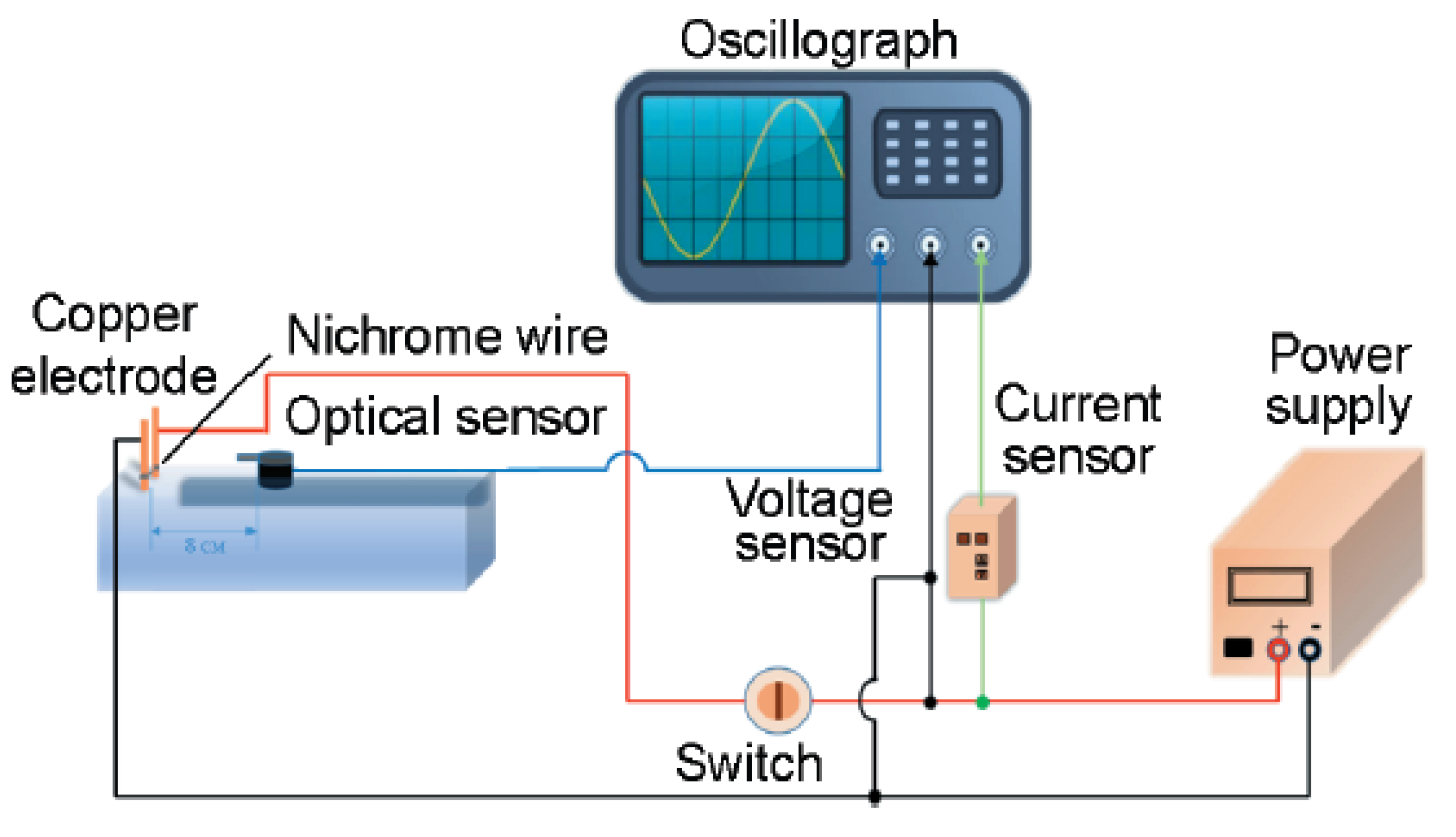
Figure 2.
Comparison of SEM morphology of B@NiF2 composites with different NiF2/B ratios: (a) B@NiF2-2%; (b) B@NiF2-4%; (c) B@NiF2-8%; (d) B@NiF2-12%; (e) B@NiF2-16%; (f) Raw B material.
Figure 2.
Comparison of SEM morphology of B@NiF2 composites with different NiF2/B ratios: (a) B@NiF2-2%; (b) B@NiF2-4%; (c) B@NiF2-8%; (d) B@NiF2-12%; (e) B@NiF2-16%; (f) Raw B material.
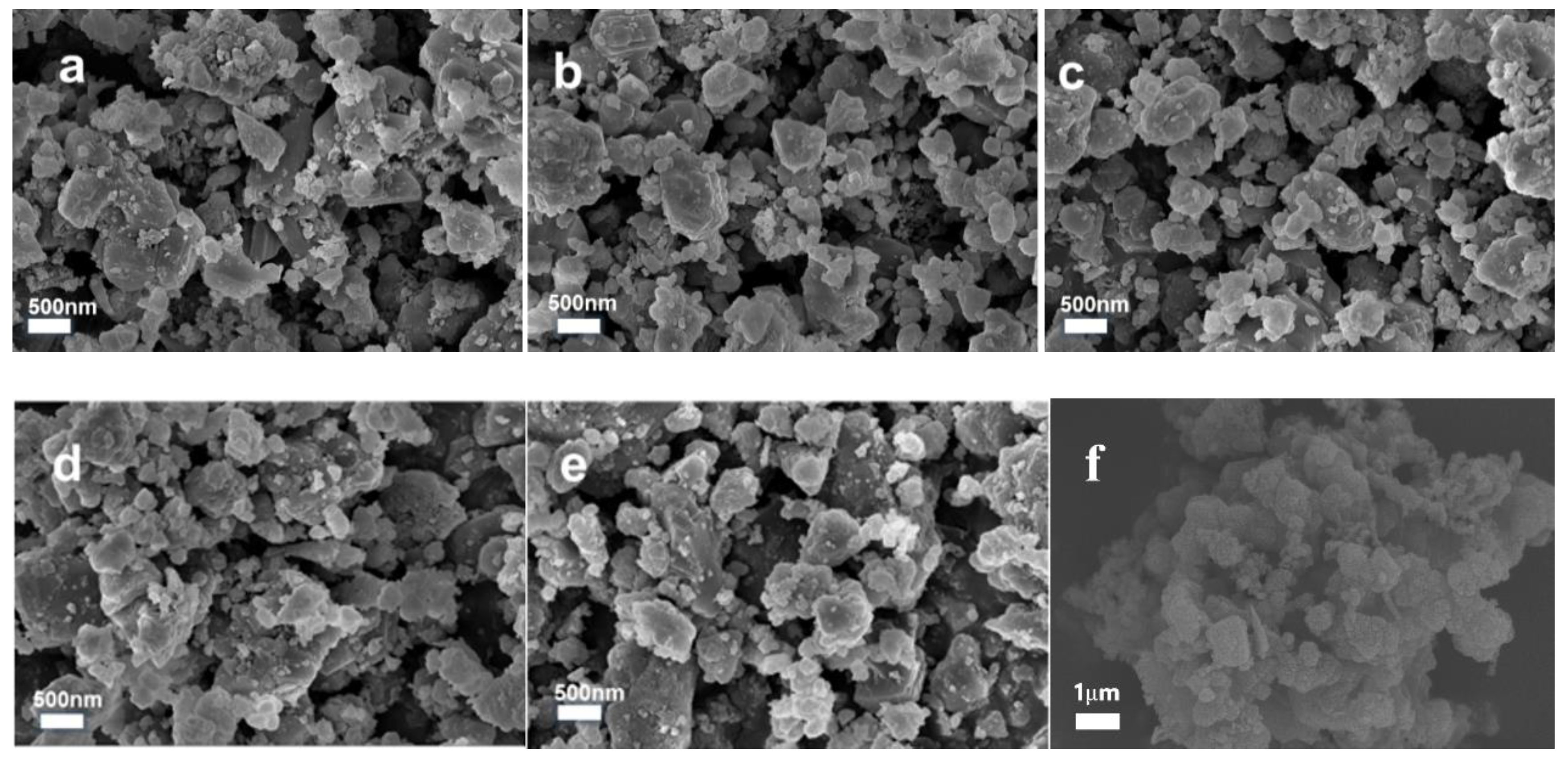
Figure 3.
XPS full spectra of B@NiF2 at different NiF2 formulation ratios.
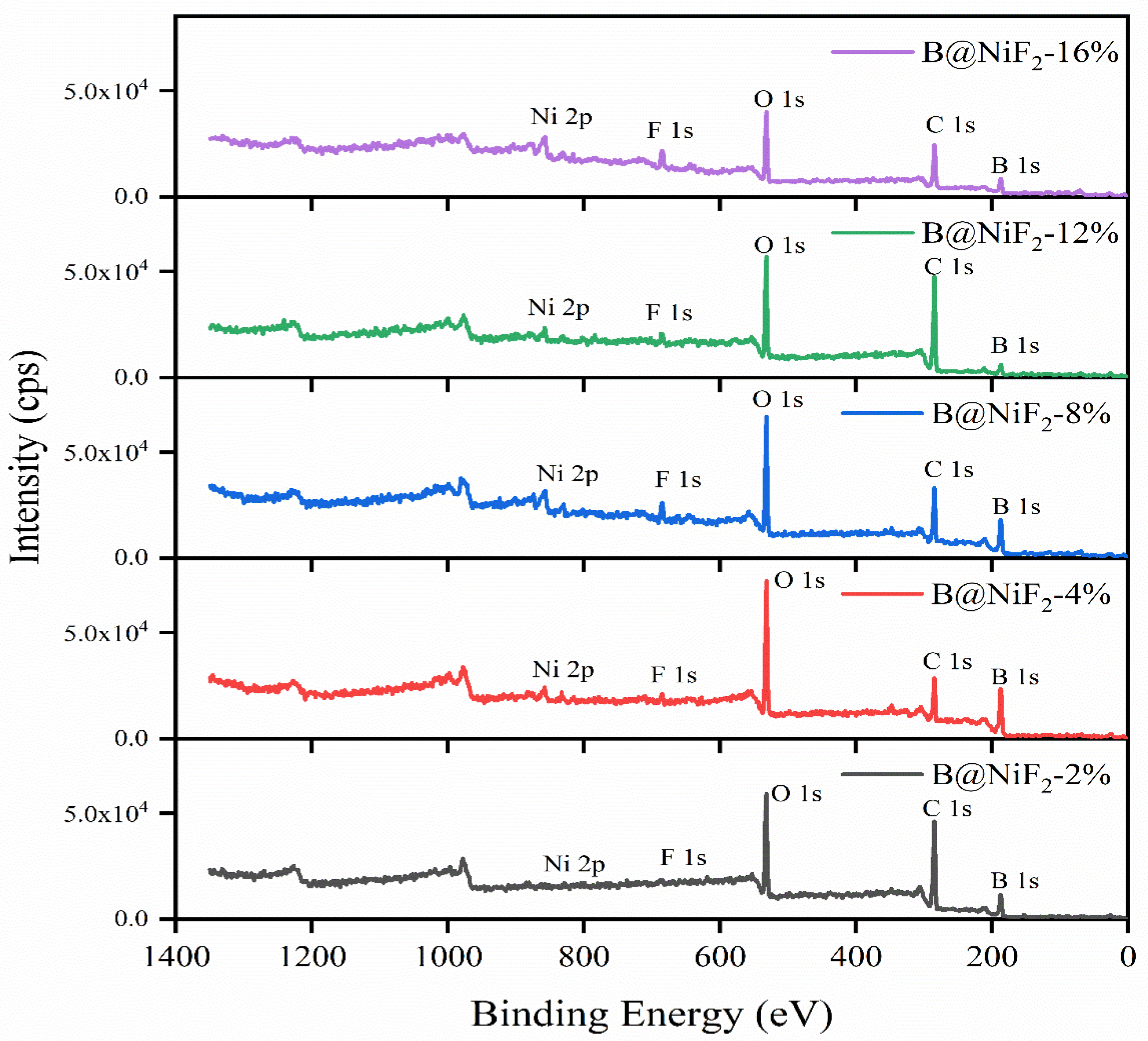
Figure 4.
High-resolution B1s spectra of B@NiF2 at different NiF2 formulation ratios.
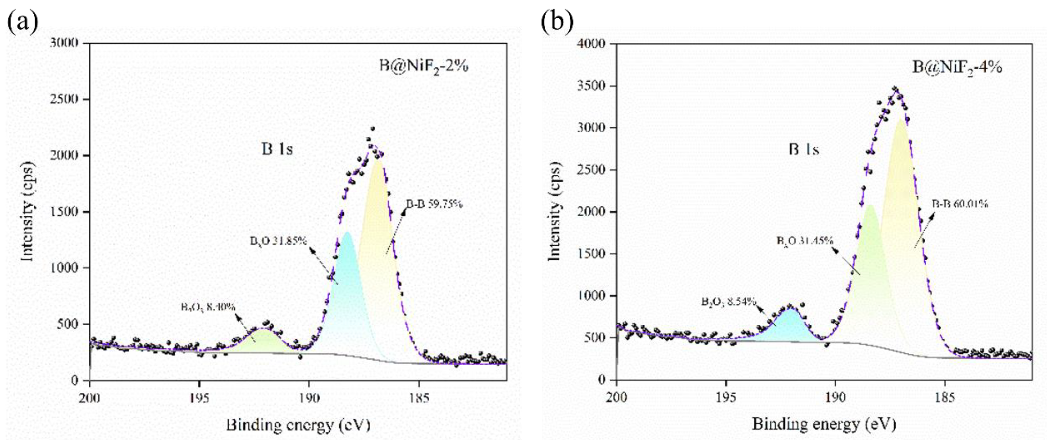
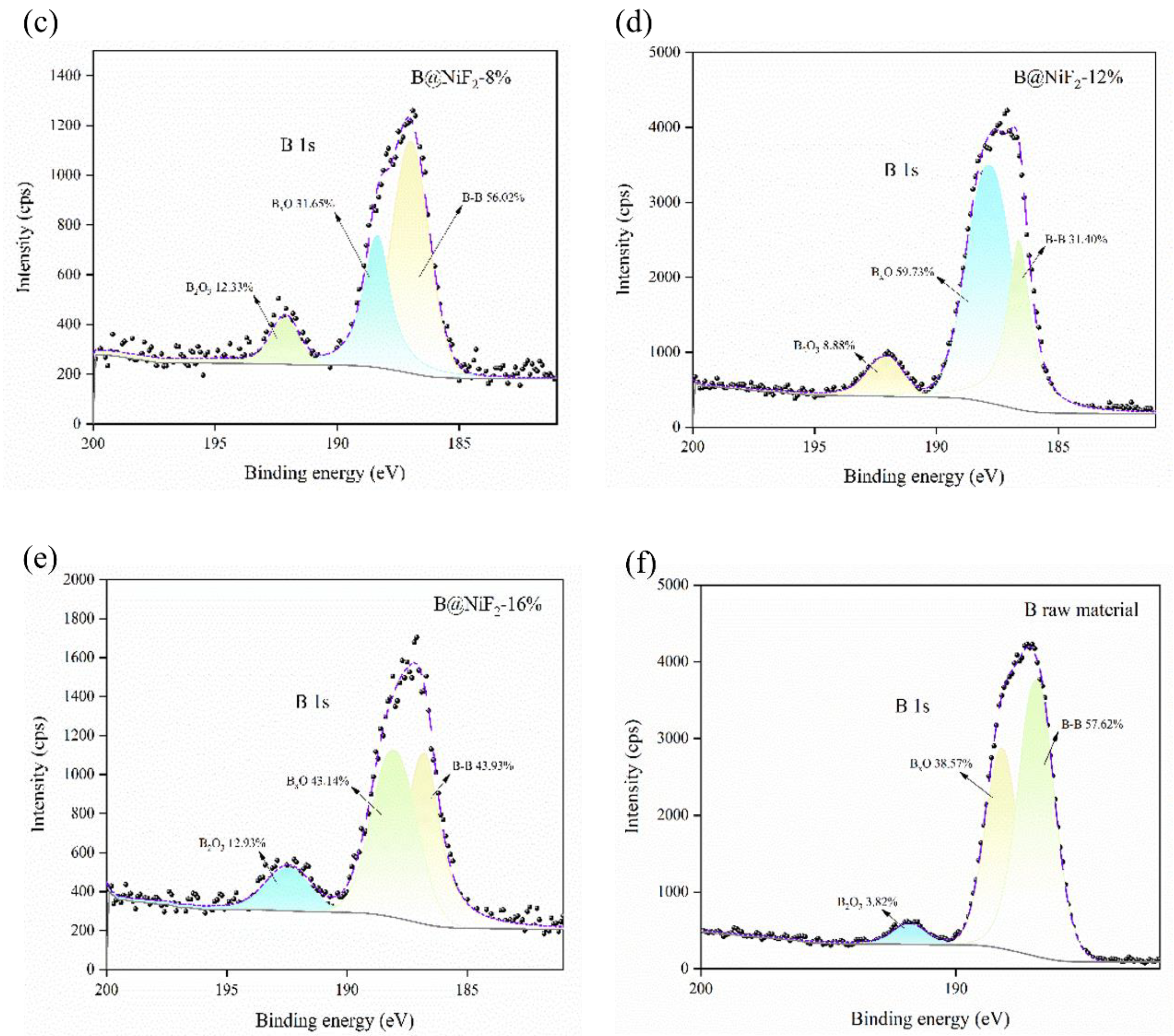
Figure 5.
XRD spectra of the scanned B@NiF2 sample.
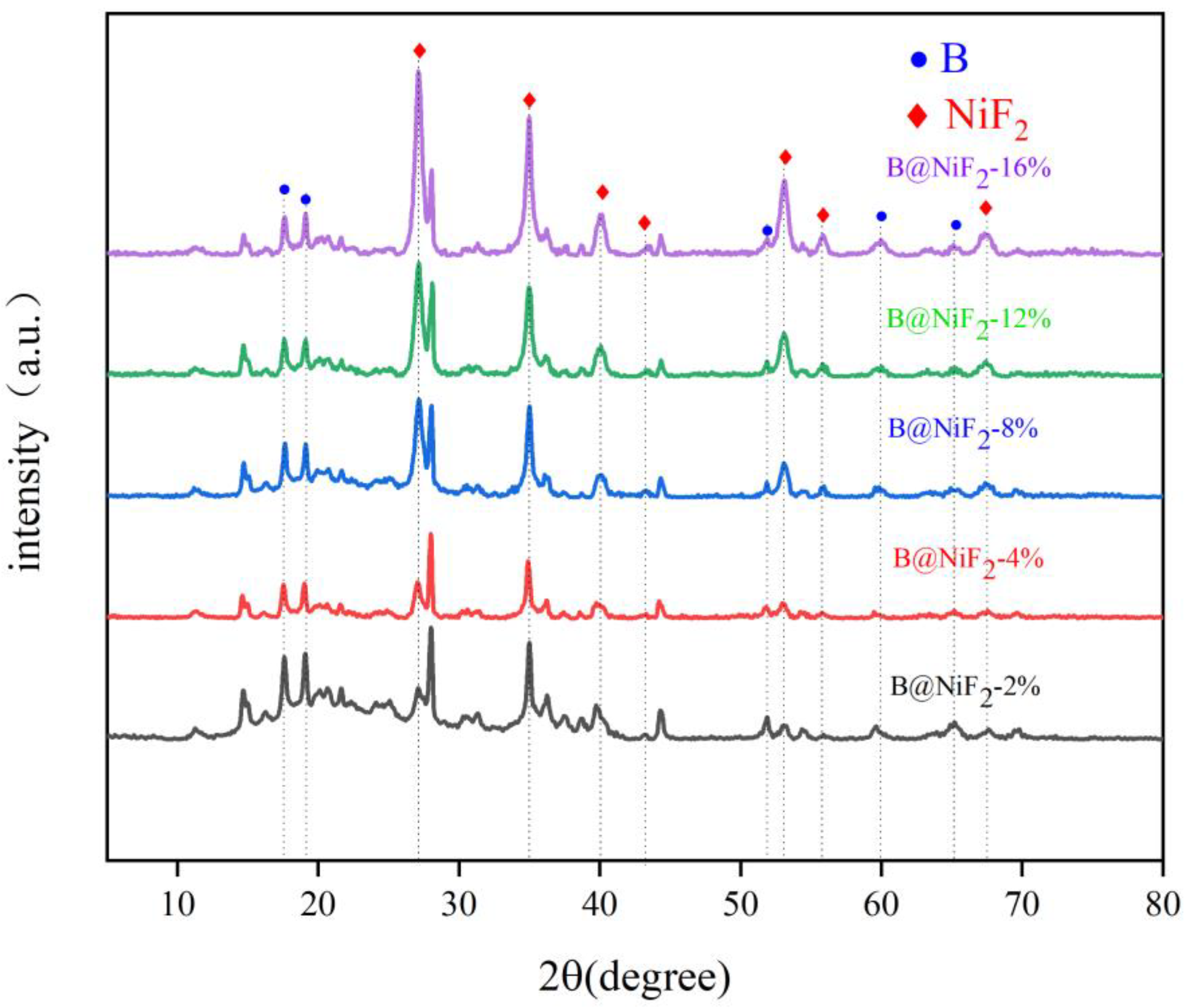
Figure 6.
(a) DSC curves of B@NiF2 with different stoichiometric ratios; (b) TG curves of B@NiF2 with different stoichiometric ratios.
Figure 6.
(a) DSC curves of B@NiF2 with different stoichiometric ratios; (b) TG curves of B@NiF2 with different stoichiometric ratios.
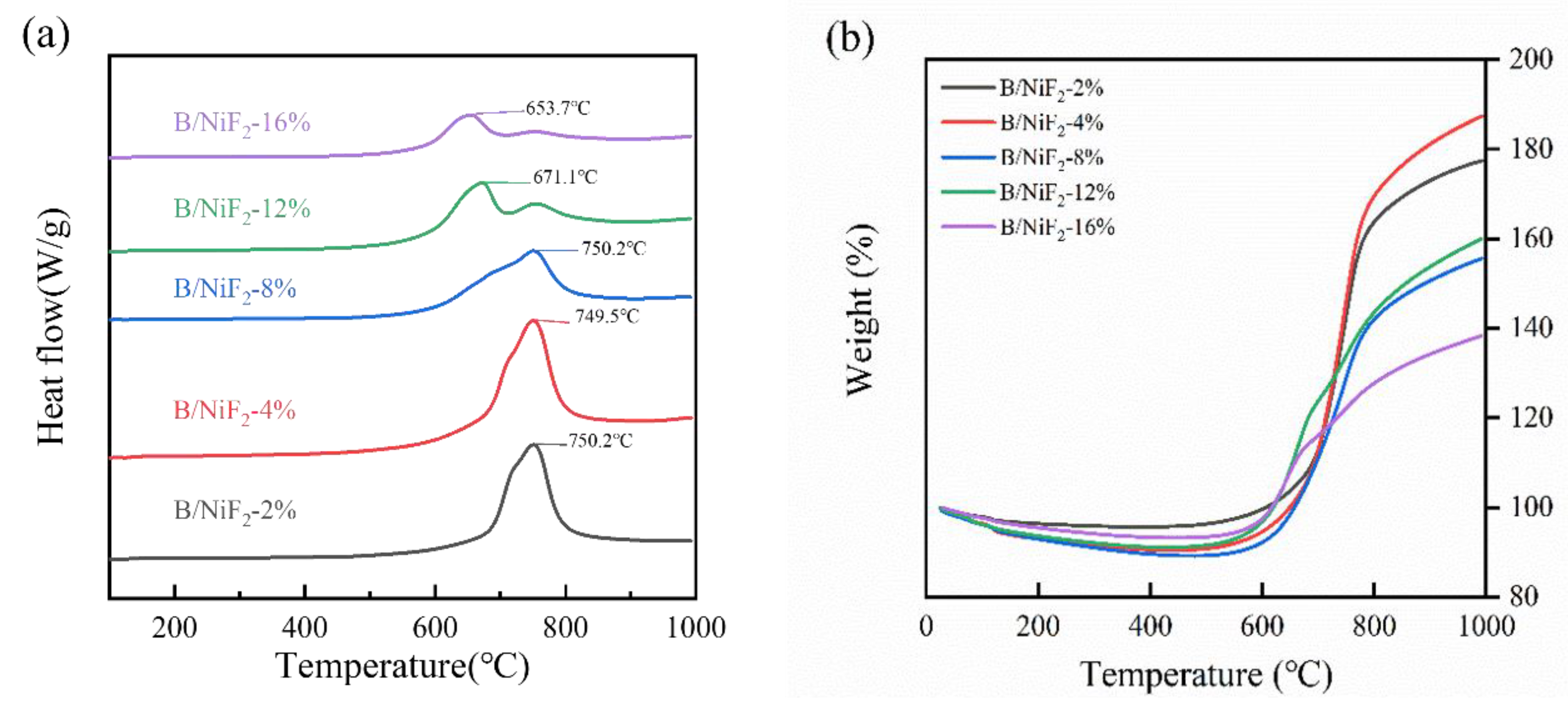
Figure 7.
(a) DSC curves of different AP and B@NiF2 mixing ratios; (b) TG curves of different AP and B@NiF2 mixing ratios.
Figure 7.
(a) DSC curves of different AP and B@NiF2 mixing ratios; (b) TG curves of different AP and B@NiF2 mixing ratios.
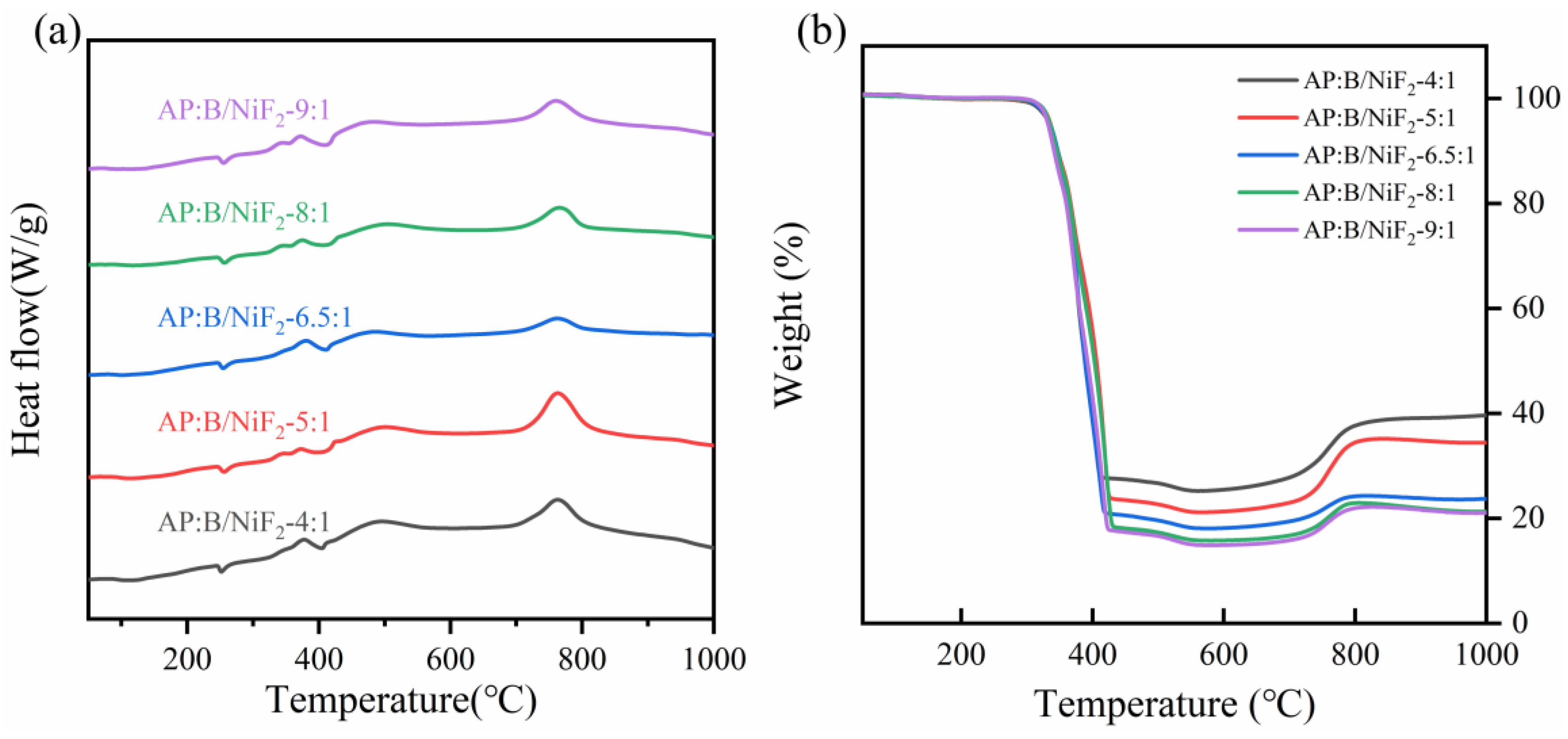
Figure 8.
(a)- (e) Schematic of ignition signals for different AP and B@NiF2 ratios in an open environment; (f) Ignition delay time and ignition energy graph.
Figure 8.
(a)- (e) Schematic of ignition signals for different AP and B@NiF2 ratios in an open environment; (f) Ignition delay time and ignition energy graph.
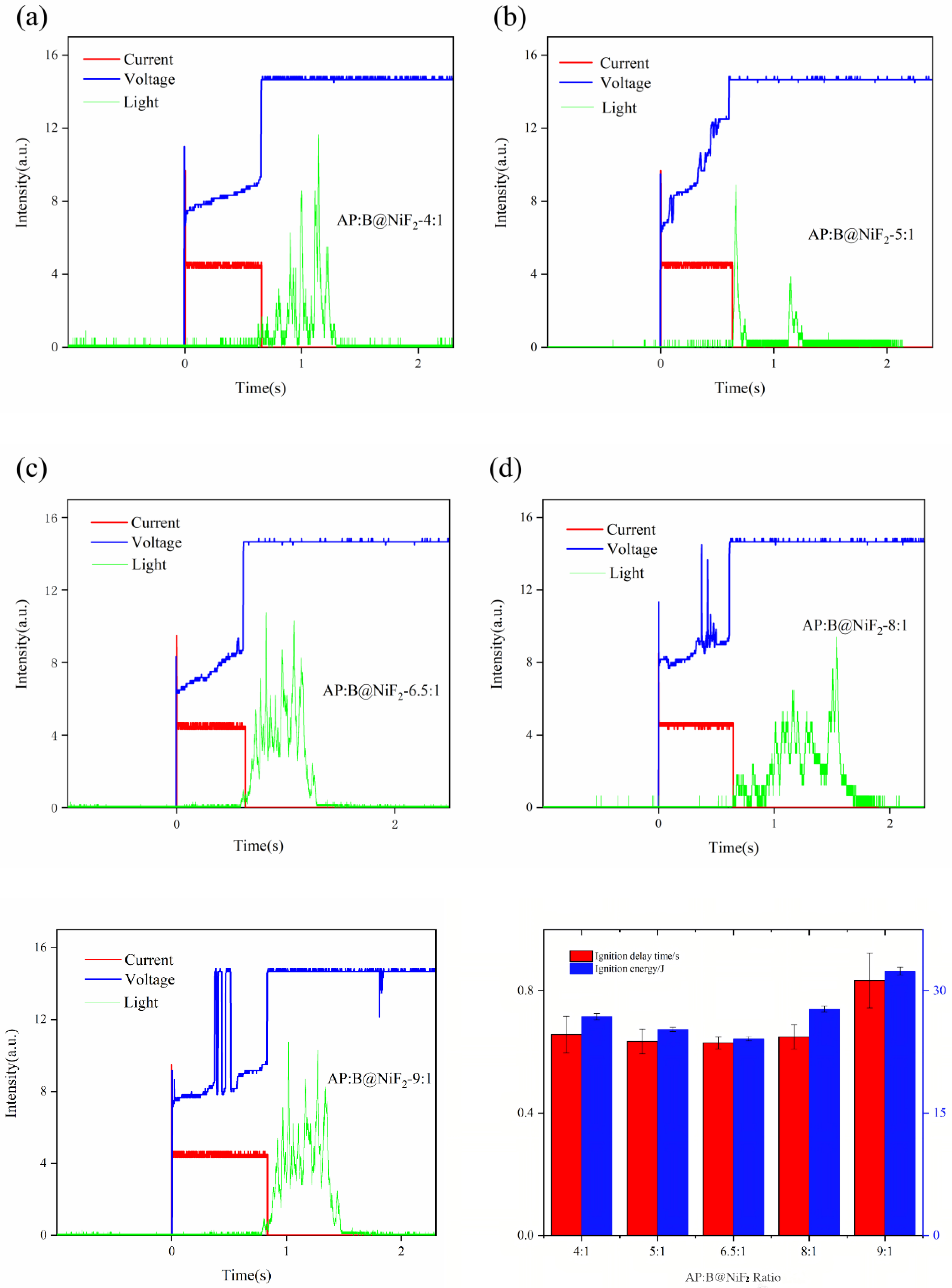
Figure 9.
High-speed photographic images of combustion at atmospheric pressure for different AP:B@NiF2 ratios. (a) 4:1, (b) 5:1, (c) 6.5:1, (d) 8:1, (e) 9:1.
Figure 9.
High-speed photographic images of combustion at atmospheric pressure for different AP:B@NiF2 ratios. (a) 4:1, (b) 5:1, (c) 6.5:1, (d) 8:1, (e) 9:1.
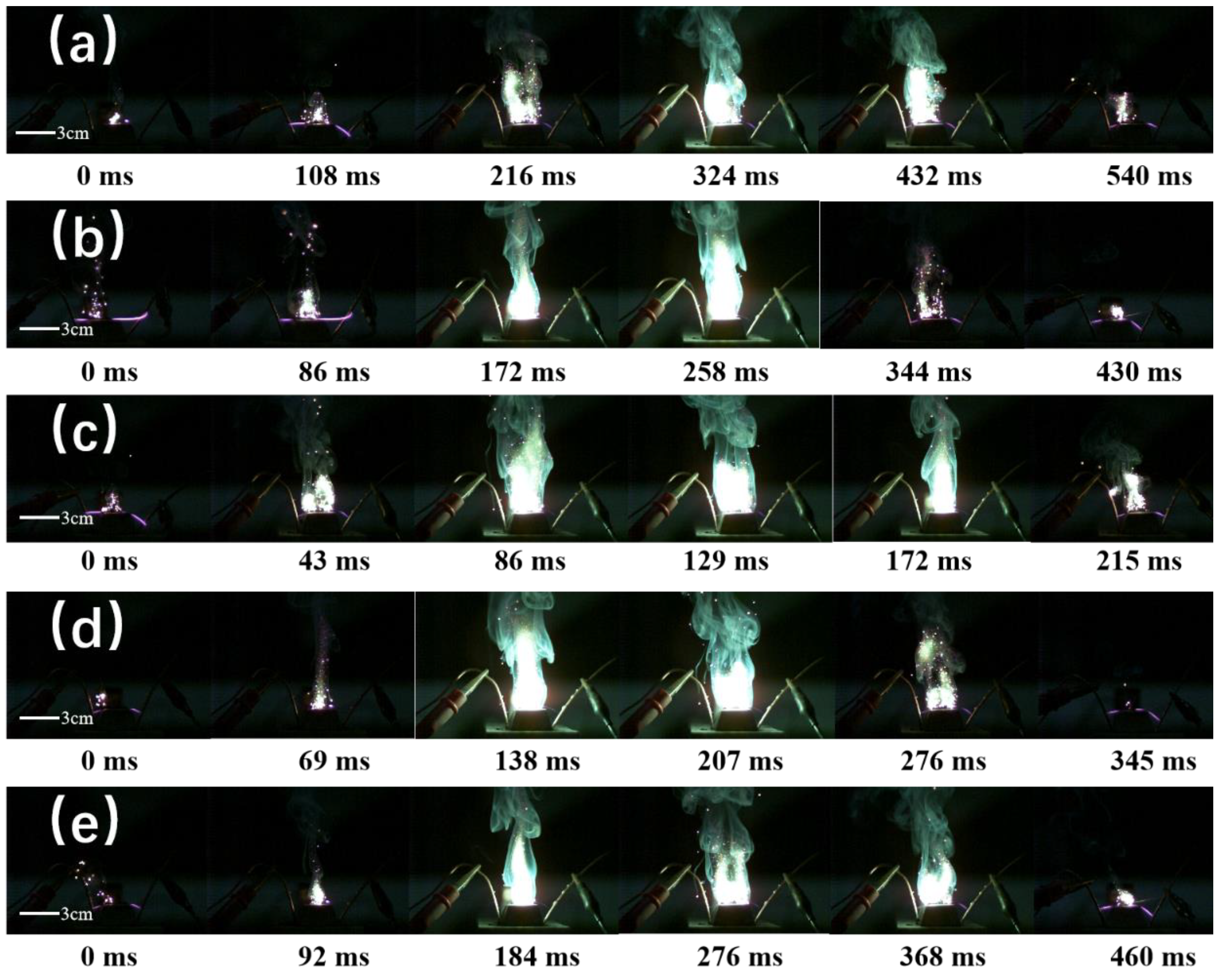

Table 1.
Thermal Analysis Data of B@NiF2 with Different Stoichiometric Ratios.
| Sample | Tp/℃ | Q/J g-1 | Δm/% |
| BN-1 | 750.2 | 8332 | 68.40 |
| BN-2 | 749.5 | 8912 | 74.58 |
| BN-3 | 750.2 | 5552 | 52.31 |
| BN-4 | 671.1 | 5587 | 52.81 |
| BN-5 | 753.7 | 1840 | 34.42 |
**Note:** In this table, Tp refers to the temperature at the exothermic peak for each sample, and Δm represents the weight loss percentage of each sample at 1000°C.
Table 2.
Bomb Calorimeter Data of B@NiF2 with Different Stoichiometric Ratios.
| Sample | BN-1 | BN-2 | BN-3 | BN-4 | BN-5 |
| Heat Release (J/g) | 14875 | 14657 | 14105 | 13799 | 13455 |
Table 3.
Thermal Analysis Data for Different AP and B@NiF2 Mixing Ratios.
| AP:B@NiF2 | Tp/℃ | Q/J·g-1 | Δm/% |
| 4:1 | 774.5 | 578 | 62.73 |
| 5:1 | 778.3 | 623 | 67.47 |
| 6.5:1 | 777.8 | 635 | 77.32 |
| 8:1 | 781.2 | 609 | 79.11 |
| 9:1 | 781.8 | 583 | 79.03 |
Table 4.
Bomb Calorimeter Data of B@NiF2 with Different AP Doping Ratios.
| AP:B@NiF2 | 4:1 | 5:1 | 6.5:1 | 8:1 | 9:1 |
| Heat Release (J/g) | 9442 | 9273 | 7731 | 7780 | 7297 |
Table 5.
Ignition Performance Data for Samples with Different AP/B@NiF2 Ratios.
| Sample | Ignition Delay Time (s) | Standard Deviation (SD) | Ignition Energy (J) | Standard Deviation (SD) |
| 4:1 | 0.673 | 0.11 | 33.81 | 0.47 |
| 5:1 | 0.652 | 0.09 | 28.64 | 0.35 |
| 6.5:1 | 0.618 | 0.03 | 22.17 | 0.23 |
| 8:1 | 0.661 | 0.08 | 26.42 | 0.39 |
| 9:1 | 0.818 | 0.17 | 27.53 | 0.51 |
Disclaimer/Publisher’s Note: The statements, opinions and data contained in all publications are solely those of the individual author(s) and contributor(s) and not of MDPI and/or the editor(s). MDPI and/or the editor(s) disclaim responsibility for any injury to people or property resulting from any ideas, methods, instructions or products referred to in the content. |
© 2025 by the authors. Licensee MDPI, Basel, Switzerland. This article is an open access article distributed under the terms and conditions of the Creative Commons Attribution (CC BY) license (http://creativecommons.org/licenses/by/4.0/).
Copyright: This open access article is published under a Creative Commons CC BY 4.0 license, which permit the free download, distribution, and reuse, provided that the author and preprint are cited in any reuse.


