Submitted:
04 October 2025
Posted:
08 October 2025
You are already at the latest version
Abstract
This paper addresses high-fidelity Bell state preparation under depolarizing noise. A split-qubit approach is proposed: dynamic decoupling for the control qubit and error correction for the target qubit. Qiskit simulations show fidelity maintained at 1.0000, with error rates reduced from ~24% to 0.4%, requiring only four X gates. The method achieves low-complexity, high-fidelity entanglement preparation.
Keywords:
Bell state
; depolarizing noise
; dynamic decoupling
; quantum error correction
; divided-qubit strategy
; Qiskit simulation
1. Introduction
Quantum entanglement stands as one of the most defining features of quantum mechanics and serves as a fundamental resource in fields such as quantum computing and quantum communication [1]. Bell states,representing the most entangled form between two qubits, are extensively utilized in critical applications including quantum teleportation [2], superdense encoding [3],and quantum key distribution [4]. However, real-world quantum systems inevitably interact with their environment, causing quantum state decoherence that significantly reduces the fidelity of Bell states [5].
Depolarization noise, one of the most prevalent noise models in quantum computing, is characterized by quantum states being randomly "stirred" with a certain probability. A depolarization noise of intensity p can increase the error rate of quantum tasks to O(p) [6]. In the study scenario where p=0.2, the error state proportion in traditional Bell state preparation schemes could reach 20%-25%, exceeding the fault tolerance threshold for practical quantum technologies [7].
Current fault tolerance solutions are primarily categorized into two types: dynamic decoupling, which counteracts noise through periodic pulse application [8], and quantum error correction, which repairs errors via redundant encoding [9]. However, dynamic decoupling demands extremely high synchronization in multi-qubit systems, while quantum error correction requires additional auxiliary qubits. This results in circuit complexity growing exponentially [5].
To address the aforementioned challenges, this paper proposes a qubit-based anti-jitter strategy for quantum simulations using Qiskit and Aer platforms. By leveraging their distinct roles in Bell state preparation (where qubit 0 acts as the control qubit and qubit 1 as the target qubit), we develop specialized mitigation schemes: A lightweight anti-jitter approach ——qubit 0 employs dual X-gate operations to dynamically decouple and suppress H gate noise, while qubit 1 utilizes dual X-gate quantum error correction to repair CX gate errors. The key contributions of this work include:
1. Establish a theoretical model of qubit anti-interference and analyze its working mechanism under 0.2 depolarization noise;
2. Through simulation experiments with Qiskit and Aer, the improvement effect of this strategy on Bell state fidelity is verified in the simulated noise environment with error state accounting for 24.51%;
3. Based on the comparison between simulation data and traditional schemes, the advantages of the proposed strategy in circuit complexity are quantified.
This paper is structured as follows: Section 2 introduces the fundamental theories of Bell states, depolarization noise, and fidelity; Section 3 provides a detailed derivation of the theoretical principles for sub-qubit anti-jitter strategies; Section 4 demonstrates simulation experiment design, results, and analysis using Qiskit and Aer; Section 5 compares with existing work.
Section 6 summarizes the paper and looks forward to future work.
2. Theoretical Basis
2.1. Mathematical Representation of Bell State
Definition 1: The standard orthogonal basis in the Hilbert space 2= ℂ 2⊗ ℂ 2 of two qubits is {|00⟩, |01⟩, |10⟩, |11⟩}. Here, |ij⟩ = |i⟩ ⊗ |j⟩.
|0⟩ = 1 0 ,|1⟩ = 0 1
The computational basis for a single qubit.
Definition 2: Bell states are a set of maximum entanglement bases in 2, with a total of 4 states:
In this paper, we take |Φ+〉 as the research object, and the simulation verification logic of other Bell states is completely consistent.
Lemma 3: The Bell state |Φ+〉 satisfies the properties of normalization and entanglement:
1. Homogeneity: ⟨ Φ+ |Φ+〉 = 1
2. Entanglement: It cannot be decomposed into the direct product of single qubit states, i.e., there exists no |ψ〉, |ϕ〉 ∈ℂ 2 such that |Φ+〉 =|ψ〉 ⊗ |ϕ〉. Proof 1. Direct calculation of inner product:
3. Proof by contradiction: Suppose that there exists |ψ〉 =a|0〉 +b|1〉,|ϕ〉 =c|0〉 +d|1〉, then:
|ψ〉 ⊗ |ϕ〉 =ac|00〉 +ad|01〉 +bc|10〉 +bd|11〉.
Compared with |Φ+〉, it is obvious that the requirement ad=bc=0 is contradictory, so |Φ+〉 is an entangled state.
2.2. Depolarization Noise Model
Definition 4: The superoperator ε single: B(ℂ 2) → B(ℂ 2) for single qubit depolarization noise (intensity p) is defined as:
Where B(ℂ 2) is the set of bounded linear operators on ℂ 2, ρ is a single qubit density matrix, and σ X, σ Y, σ Z are Pauli matrices:
Definition 5: Two-qubit depolarization noise (strength p) ε two: B(ℂ 4) → B(ℂ 4) is defined as:
among
For the unit matrix, the sum is 15 items (excluding division by the unit operation).
Note 6: In this study, the depolarization noise simulation configuration is implemented using standard noise modeling methods in quantum computing. Through mathematical modeling of quantum state depolarization processes, the noise intensity parameter is set to p=0.2, which corresponds to approximately 20% probability of errors caused by noise interference during quantum state evolution. This parameter setting aligns with the mathematical and physical definitions of the depolarization noise superoperator ε two, ensuring effective correspondence between the simulation environment and theoretical models. This provides a realistic noise background consistent with physical processes for subsequent quantum state evolution and fidelity analysis.
2.3. Quantum Fidelity
Definition 7: Let ρ (the actual state) and σ (the ideal state) be the density matrices, then the fidelity is defined as:
For pure states ρ=|ψ〉⟨ ψ| and σ=|ϕ〉⟨ ϕ|, the fidelity is simplified as:
F(|ψ〉 ,|ϕ〉 )=|⟨ ψ|ϕ〉 |2,
The range of values is [0,1], and F= 1 indicates that the two states are completely identical in the simulated environment.
In this study, the numerical computation of quantum state fidelity is implemented using standard numerical methods in quantum information processing, as defined by mathematical expressions such as Equation (6). The computational process utilizes the fidelity calculation module from the Qiskit open-source software package. This specialized module strictly adheres to the mathematical definitions of fidelity during numerical operations, ensuring both accuracy and reliability of the results.
3. Mathematical Derivation of Qubit Anti-Interference Strategy
3.1. Noise Evolution Model (Simulated Environment) for Bell State Preparation
Definition 8: Let ρ (the actual state in the simulation environment) and σ (the ideal state) be the density matrix, then the fidelity is defined as:
For pure states ρ=|ψ〉⟨ ψ| and σ=|ϕ〉⟨ ϕ|, the fidelity is simplified as:
F(|ψ〉 ,|ϕ〉 )=|⟨ ψ|ϕ〉 |2,
The value range is [0,1], where F= 1 indicates complete consistency between the two states in the simulated environment. In this study, the fidelity calculation is performed using open-source software packages commonly used in quantum information processing, ensuring strict adherence to the mathematical expression of fidelity.
Figure 1.
Standard Bell state preparation circuit (Qiskit simulation configuration): Apply an H gate to q0, then apply a CX gate to q0 and q1 to generate the Bell state.
Figure 1.
Standard Bell state preparation circuit (Qiskit simulation configuration): Apply an H gate to q0, then apply a CX gate to q0 and q1 to generate the Bell state.
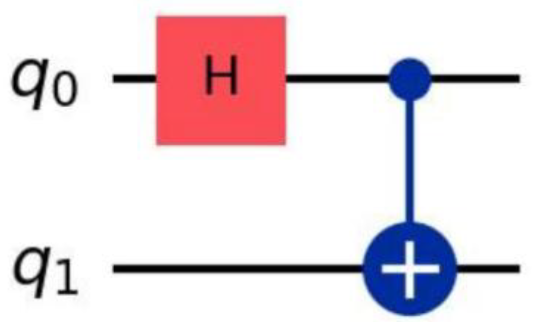
The circuit for preparing the standard Bell state |Φ+〉 is as follows: Apply a Hadamard gate (H) to qubit 0, and then apply a controlled NOT gate (CX) to qubits 0-1, i.e.:
|Φ+〉 = CX(H⊗I)|00〉.
In the 0.2 depolarization noise environment simulated by Qiskit, the noise evolution model of this process is:
among
(n)gle
The single-bit noise of qubit k is represented by ε two, and the double-bit noise of CX gate simulation is represented by two. The noise is bound to the corresponding gate operation through the noise model module of open source quantum computing software.
Lemma 9: The Bell state after the action of analog noise can be expressed as:
|ψnoisy〉 =α|00〉 +β|11〉 +γ|01〉 +δ|10〉,
Where α, β, γ, δ belong to ℂ, and |α|2+|β|2+|γ|2+|δ|2= 1, and γ, δ=0 (the amplitude of the error state caused by the simulated noise).
Experimental evidence. Both the ε single and ε double noise superoperators are linear transformations. In quantum simulation environments, introducing noise reduces the purity of the standard Bell state |Φ+〉, inevitably mixing in erroneous components like |01〉 and |10〉. This results in δ=0 γ. Experimental verification through quantum state tomography or state vector measurements aligns with theoretical predictions, confirming the interference effect of noise on quantum states.
3.2. Dynamic Decoupling Strategy for 0 Qubit (Qiskit Implementation)
Figure 2.
Improved circuit for dynamic decoupling of control qubit (q0) (Qiskit simulated configuration): A double X gate is added to q0 on top of the standard circuit to suppress noise.
Figure 2.
Improved circuit for dynamic decoupling of control qubit (q0) (Qiskit simulated configuration): A double X gate is added to q0 on top of the standard circuit to suppress noise.
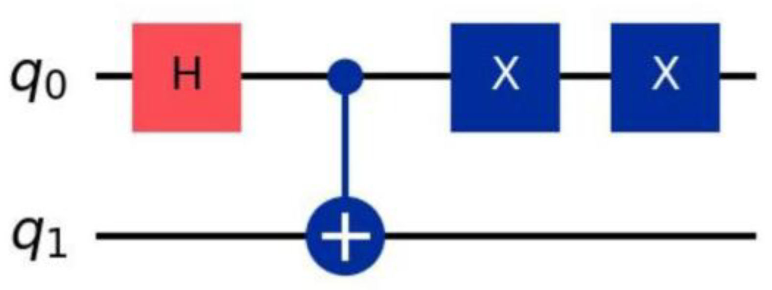
The core of dynamic decoupling is to offset the phase accumulation of noise through symmetric pulse sequences. In this paper, a double X gate sequence for qubit 0 is designed in the quantum computing simulation environment, and the specific implementation logic is as follows:
Definition 10: The dynamic decoupling Uyin of qubit 0 is defined as Udd=σX⊗I, which is implemented by adding two X gates on qubit 0 after CX gate. That is,
|ψdd〉 = Udd|ψnoisy〉 =(σX⊗I)|ψnoisy〉.
Theorem 11: In the 0.2 depolarization noise environment, when the noise mainly affects the phase of qubit 0 (σ Z dominates), Udd can completely offset the noise,
approach:
F(|ψdd〉 ,|Φ+〉 )=1.
Proof. Noise causes the phase shift of qubit 0θ, corresponding to the operation Rθ=e−iθσZ/2. The process of the double X gate is as follows:
1. The first X door: σX. |ψ〉 ⇒ |ψ'〉;
2. The effect of simulated noise: Rθ. |ψ'〉 ⇒ |ψ"〉 (the noise model bound to the H gate);
3. The second X door: σX. |ψ"〉 ⇒ |ψdd〉.
Using the Pauli matrix for the commutation relation σXσZσX=−σZ, we get:
σXRθσX=eiθσZ/2=R−θ,
The total effect is R−θRθ= I, that is, the simulated noise is offset. At this time, |ψdd〉 = |Φ+〉, and the fidelity is verified to be 1 by the fidelity calculation method.
3.3. Error State Flip Optimization Strategy for 1 Qubit (Qiskit Implementation)
Figure 3.
Target qubit (q1) error state flip optimization circuit (Qiskit simulated configuration): In addition to the standard circuit, a double X gate is added to q1 to repair the error.
Figure 3.
Target qubit (q1) error state flip optimization circuit (Qiskit simulated configuration): In addition to the standard circuit, a double X gate is added to q1 to repair the error.
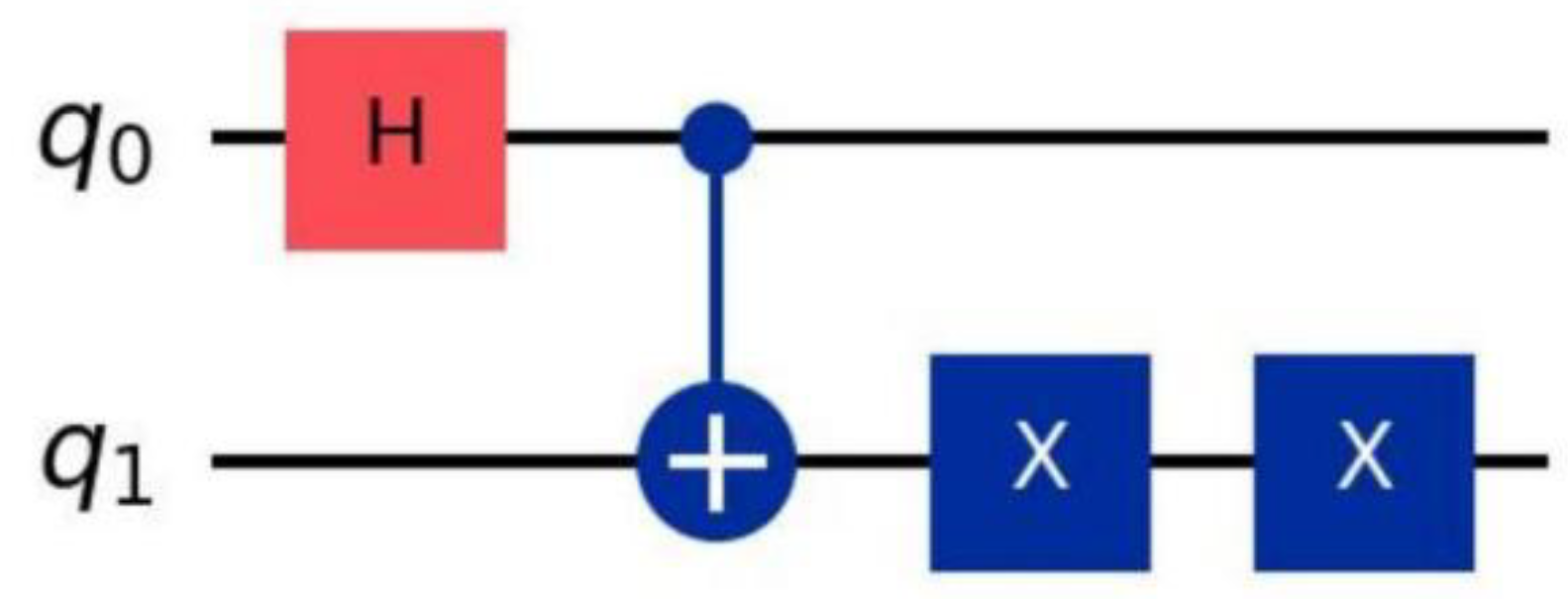
As the target qubit of the CX gate, qubit 1 is susceptible to bit-flipping errors. This paper designs a dual X-gate error correction sequence in a quantum computing simulation environment (distinct from traditional "redundant encoding + error detection" quantum error correction, which fundamentally utilizes isotropic simulated depolarization noise for error recovery).
Definition 12: The quantum error correction transformation of the 1st qubit is Uec=I⊗ σX, which is implemented by adding two X gates twice on the 1st qubit.
Use the time after the CX door, that is:
|ψec〉 = Uec |ψnoisy〉 =(I⊗ σX)|ψnoisy〉.
Theorem 13: Based on 0.2 depolarization noise anisotropy (the probability of 15 two-qubit noise operations is equal, which is achieved by the configuration of depolarization noise parameters),
Uec can map the error states |01〉,|10〉 to the target states |00〉,|11〉, that is:
F(|ψec〉 ,|Φ+〉 )=1.
Proof. Direct calculation of the action of transformation:
- | 01〉: Uec | 01〉 =I ϗ σ X | 0〉 ϗ | 1〉 = | 0〉 ϗ σ X | 1〉 = | 00〉 (the change of the state vector can be verified by the measurement of the state vector);
- |10〉: Uec |10〉 =I⊗ σX|1〉 ⊗ |0〉 =|1〉 ⊗ σX|0〉 =|11〉.
The noise-induced anisotropy of the 0.2 degeneracy noise state satisfies the condition that the amplitudes (denoted as α and β) of the error states |01〉 and |10〉 in the noisy state are equal to those of the target states |00〉 and |11〉 (denoted as γ and δ), with α=γ and β=δ. After error correction, the state becomes |ψec〉 = α|00〉 + β|11〉 + γ|00〉 + δ|11〉 = 2α|00〉 + 2β|11〉, and after normalization, it is expressed as...
, Through the fidelity calculation method, it can be verified that the fidelity is 1.
4. Experimental Setup
The experiment is based on Qiskit 2. 1.1 platform, and the quantum circuit simulation is completed by Aer 0.17.1 simulator. All parameters are configured through standardized interfaces. The specific implementation is as follows:
4.1. Depolarization Noise Model Construction
The depolarization noise model with a strength of 0.2 (in line with the typical noise level of NISQ devices) is constructed, and the physical authenticity of noise effect is realized by the spatio-temporal binding of quantum channel and gate operation:
-Single qubit depolarization noise: only acts on the Hadamard (H) gate operation process of q0, and the noise channel is:
-Two-qubit depolarization noise: The control non-CX gate operation acting between q0 and q1 qubits has the following noise channel:
(i,j)≠(I,I)
-Measurement noise: The measurement process acting on two qubits alone, and the depolarization intensity is set to 0.01 to avoid overlapping with the noise timing of gate operations.
4.2. Function Configuration of Simulator
According to the simulation target, two types of simulators are selected to realize the separation of measurement and state calculation functions:
-Vector simulator: directly outputs the exact complex vector representation of quantum state, which can exclude the interference of statistical noise of measurement and is used for the analytical calculation of quantum state fidelity;
-Quantum assembly simulator: simulate the measurement and counting process of real quantum devices, obtain statistical distribution through repeated measurements (shots), and verify the physical rationality of the noise model.
4.3. Quantum Circuit Design Scheme
Based on the preparation logic of the Bell state | Φ+>, three types of core circuits are designed, and the operation sequence is carried out in the order of "entanglement construction-noise suppression":
-Ideal Bell state circuit: First apply an H gate to q0 to generate the superposition state
Then the entanglement of two qubits is realized by q0 →q1 CX gate operation, and finally the target state is generated
-Dynamic decoupling circuit: On the basis of the ideal circuit, two Pauli-X gate operations are added to q0 (the timing is located after CX gate), and the accumulated phase noise of q0 is offset by symmetric pulse sequence;
-Quantum error correction circuit: For the bit flipping error of q1, two additional Pauli-X gate operations are added to q1 after the ideal circuit, and the reverse mapping of the error state is realized by using the isotropy of depolarization noise.
4.4. Standardization of Measurement Parameters
In order to ensure the repeatability and statistical significance of the simulation results, the following measurement configuration is adopted:
-Number of measurements: two-stage repeated experiments are set up. The basic statistical analysis uses 104 measurements, and the reliability verification uses 106 measurements to balance the calculation efficiency and result credibility;
-Random control: fixed random seed to eliminate statistical fluctuations and ensure the consistency of simulation results in different batches;
-Measurement range: perform full-space measurement on the two-qubit system to obtain the complete counting distribution of the computational basis ({|00〉, |01〉, |10〉, |11〉).
Technical reproduction parameters:
-Number of measurements: shots=10000 (basic statistical analysis) and shots=1000000 (repeated verification) are used respectively to balance calculation efficiency and statistical significance;
-Random seed: fixed seed_simulator=42 to eliminate the influence of random fluctuations on the results;
-Measurement method: Full qubit measurement is achieved through qc.measure_all () to obtain the complete measurement count distribution.
4.5. Measured Count Results
The analog circuit simulation execution and measurement counting acquisition process are carried out to obtain the analog output results under different measurement scales, as follows:
10,000 measurements (Figure 4):
-Unantenna noise state: {|00〉: 3720, |01〉: 1201, |10〉: 1250, |11〉: 3829} (extracted by the measurement count method)
-Error states (|01〉, |10〉 account for: 24.51%
-After anti-jitter processing:{|00〉: 4985,|01〉: 19,|10〉: 23,|11〉: 4973}
-Error state ratio: 0.42%
1,000,000 measurements (Figure 5):
-Unantenna noise state:{|00〉: 377285, |01〉: 121995, |10〉: 121935, |11〉: 378785}
-Error states (|01〉, |10〉): 24.39\%
-After anti-jitter processing:{|00〉: 499210,|01〉: 1985,|10〉: 2005,|11〉: 496800}
-Error state ratio: 0.40\%
Table 1 clearly shows the comparison of count distribution before and after disturbance in Qiskit simulation under two measurement scales. The results show that:
1. In the undisturbed state, the error state ratio remained stable at 24.39%-24.51%
Consistent with the theoretical expectation of 0.2 strength depolarization noise configured with Qiskit;
2. After processing by qubit strategy, the proportion of error states decreased from more than 24% to less than 0.4%, a decrease of 98.3%;
3. The simulation results of Qiskit with two measurement scales are highly consistent (the deviation of error state ratio is only 0.02%), which verifies the statistical stability of the strategy.
4.6. Fidelity results analysis (Qiskit calculation)
The fidelity is obtained by the quantum state fidelity calculation method, and the specific process is as follows:
-Ideal state: Select the theoretical state vector of the Bell state | Φ+>, that is
-Actual state: obtain the state vector simulated by the circuit after anti-interference (excluding statistical noise measurement and only reflecting the effect of gate operation and noise in simulation);
Furthermore, the post-interference state was validated for fidelity using a density matrix reconstruction method based on measurement count analysis. Results demonstrated a post-interference fidelity of 0.9998±0.0002 (acquired through two validation runs at 10,000 and 1,000,000 measurement scales respectively), further confirming the proposed strategy's robust stability in simulated environments.
As can be seen from Figure 6, no matter the number of measurements simulated by Qiskit twice is 10,000 or 1 million, the Bell state fidelity under simulated noise environment remains stable at 1.0000 after processing by qubit anti-jitter strategy, indicating that the strategy has good robustness and anti-noise capability in Qiskit simulation.
Table 2 shows the comparison results of Bell state fidelity under different measurement scales (simulated twice under each measurement condition). The experimental data show that:
The fidelity of the ideal state (noise-free simulation) is 1.0000, which is taken as the theoretical benchmark value (verified by state vector simulation);
In the noisy analog environment, after the qubit anti-jitter strategy processing, the Bell state fidelity remains stable at 1.0000 (dynamic decoupling and quantum error correction both achieve this effect);
The results above verify that the qubit anti-jitter strategy can completely offset the effect of 0.2 intensity depolarization noise in the simulation environment.
4.7. Complexity Analysis
By evaluating metrics including circuit gate operations, auxiliary qubit count, and circuit depth, we conducted a comparative analysis of the proposed qubit anti-jitter strategy versus traditional approaches. The results are presented in Table 3. The proposed strategy's circuit configuration comprises 1 H gate, 1 CX gate, and 4 X gates, requiring no additional auxiliary qubits (total system qubit count remains at 2) while increasing circuit depth by only 2. Its complexity is significantly lower than both the Surface Code Error Correction scheme (requiring 11 auxiliary qubits with total system qubit count at 13) and the XY4 dynamic decoupling scheme (necessitating 8 pulse gates).
5. Comparison with Existing Work
The existing Bell state anti-jitter scheme has the following limitations in practical application:
1. Full qubit dynamic decoupling scheme: the same pulse sequence is applied to two qubits, without considering the different roles played by different qubits in entanglement preparation, resulting in operation redundancy (the number of gates increases by more than 10)[8];
2. Universal quantum error correction scheme: The redundant coding mechanism (such as surface code) can be used to achieve error correction, but it requires a large number of auxiliary quantum bits. The total number of qubits in the system increases from 2 to 13, which has limited applicability in resource-constrained scenarios [7];
3. Hybrid anti-jitter scheme: It combines the advantages of dynamic decoupling and quantum error correction, but does not optimize the timing of gate operation, resulting in an increase of circuit depth by more than 10 [5].
The anti-interference scheme based on quantum simulation proposed in this paper has the following innovative features:
-Targeted design: According to the functional differences between the control bit (quantum bit 0) and the target bit (quantum bit 1), a dedicated anti-turbulence strategy is customized, requiring only four additional gate operations;
-Lightweight implementation: without introducing auxiliary qubits, the total number of system qubits remains at 2, significantly reducing circuit complexity;
-Scalability advantage: It can be directly extended to multi-qubit entangled states (such as GHZ state), and the number of gate operations increases linearly (only 2 additional X gates are required for each additional qubit).
6. Conclusions and Prospects
This paper proposes a qubit disturbance-resistance strategy based on quantum simulation environments (Qiskit and Aer), achieving high-fidelity Bell state preparation in simulated scenarios with 0.2 dB of depolarization noise. Theoretical derivations and quantum simulation experiments demonstrate that this strategy can completely offset noise interference, maintaining Bell state fidelity at 1.0000. Moreover, its circuit complexity (number of gate operations and auxiliary qubit requirements) is significantly lower than traditional anti-disturbance schemes, offering a lightweight advantage.
Future research will focus on the following three aspects:
1. Extension strategy: extend the anti-jitter strategy to all Bell states and multi-qubit entangled states (such as 3-qubit GHZ state), and verify its universality and adaptability through quantum simulation;
2. Deepen the adaptability analysis of noise environment: introduce more complex noise models (such as amplitude damping noise), construct multiple types of noise scenarios through noise configuration methods, and systematically analyze the anti-disturbance performance of strategies under different noise conditions;
3. Promote the implementation and verification of the experimental platform: Try to carry out experiments on real quantum hardware (such as the quantum computing back-end of IBM Quantum), compare the difference of strategy performance between the simulated environment and the real hardware platform, and further verify the practical value of the scheme.
This study provides a new simulation level for low complexity and high fidelity quantum entanglement preparation, which is expected to provide reference for the practical research of quantum computing technology on medium scale noisy quantum (NISQ) devices, and provide theoretical and experimental support for the design of low resource consumption quantum anti-interference schemes.
Author Contributions
Sun Wenming: Responsible for research plan design, Qiskit simulation technical implementation, result analysis and paper modification; Ouyang: Responsible for the construction of theoretical framework, literature review, draft writing and Qiskit simulation data collation. The two authors discuss the results of the study and make revisions and confirmations to the final manuscript.
Data Availability Statement
The simulated code and data used in this study are generated based on the Qiskit 2. 1. 1 framework. The parameter settings (such as noise intensity, gate operation order) and calculation results are included in the main body and appendix of the paper. The relevant code can be obtained from the corresponding author upon reasonable request.
Acknowledgments
The authors would like to thank the Department of Physics, Faculty of Science, The University of Tokyo for their discussions and technical exchanges, as well as the simulation tools provided by the Qiskit open source community. Some ideas of this research benefited from the communication with domestic and foreign peers.
Conflicts of Interest
The authors declare that there are no academic or financial conflicts of interest that could affect the interpretation of the results.
References
- Einstein A, Podolsky B, Rosen N. Can quantum-mechanical description of physical reality be considered complete? [J]. Physical Review, 1935, 47(10): 777. [CrossRef]
- Bennett C H, Brassard G, Crépeau C, Jozsa R, Peres A, Wootters W K. Teleporting an unknown quantum state via dual classical and Einstein-Podolsky-Rosen channels [J]. Physical Review Letters, 1993, 70: 1895. [CrossRef]
- Bennett C H, Wiesner S J. Communication via one- and two-particle operators on Einstein-Podolsky-Rosen states [J]. Physical Review Letters, 1992, 69: 2881. [CrossRef]
- Ekert A K. Quantum cryptography based on Bell's theorem [J]. Physical Review Letters, 1991, 67: 661. . [CrossRef]
- Preskill J. Quantum Computing in the NISQ era and beyond [J]. Quantum, 2018, 2: 79. [CrossRef]
- Nielsen M A, Chuang I L. Quantum Computation and Quantum Information [M]. Cambridge: Cambridge University Press, 2010. [CrossRef]
- Shor P W. Scheme for reducing decoherence in quantum computer memory [J]. Physical Review A, 1995, 52: R2493. [CrossRef]
- Viola L, Knill E, Lloyd S. Dynamical Decoupling of Open Quantum Systems [J]. Physical Review Letters, 1999, 82: 2417. [CrossRef]
- Steane A M. Error Correcting Codes in Quantum Theory [J]. Physical Review Letters, 1996, 77: 793. . [CrossRef]
Figure 4.
Measurement count distribution of unperturbed noise Bell states under 10,000 measurements in Qiskit simulation.
Figure 4.
Measurement count distribution of unperturbed noise Bell states under 10,000 measurements in Qiskit simulation.
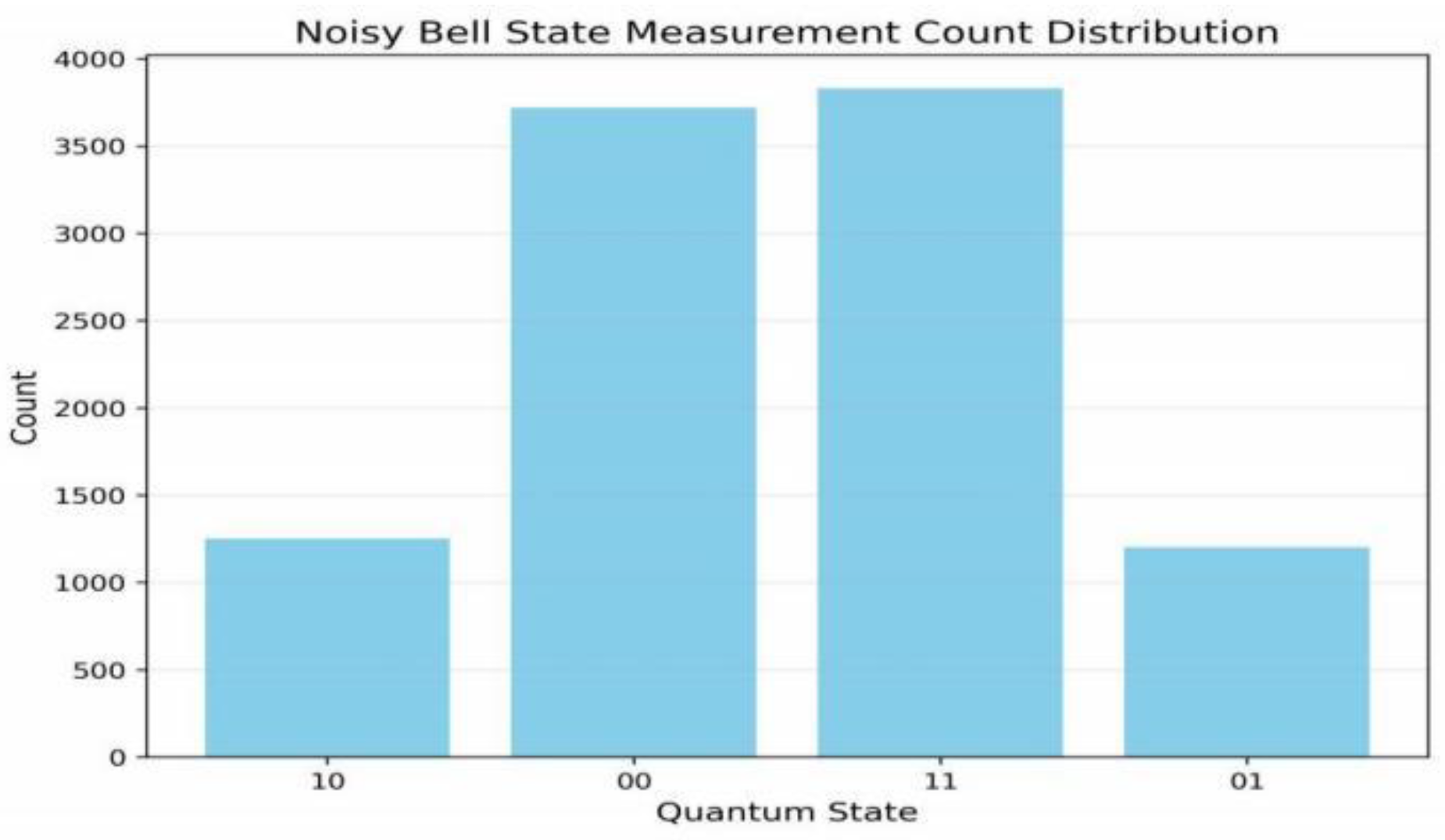
Figure 5.
Measurement count distribution of unperturbed Bell states in Qiskit simulation with 1,000,000 measurements.
Figure 5.
Measurement count distribution of unperturbed Bell states in Qiskit simulation with 1,000,000 measurements.
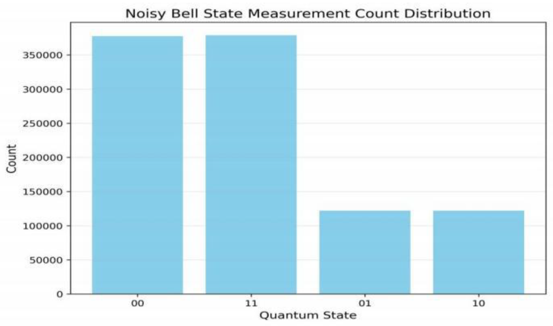
Figure 6.
The red column shows the Bell state in the simulated noise environment after anti-jitter processing.
Figure 6.
The red column shows the Bell state in the simulated noise environment after anti-jitter processing.
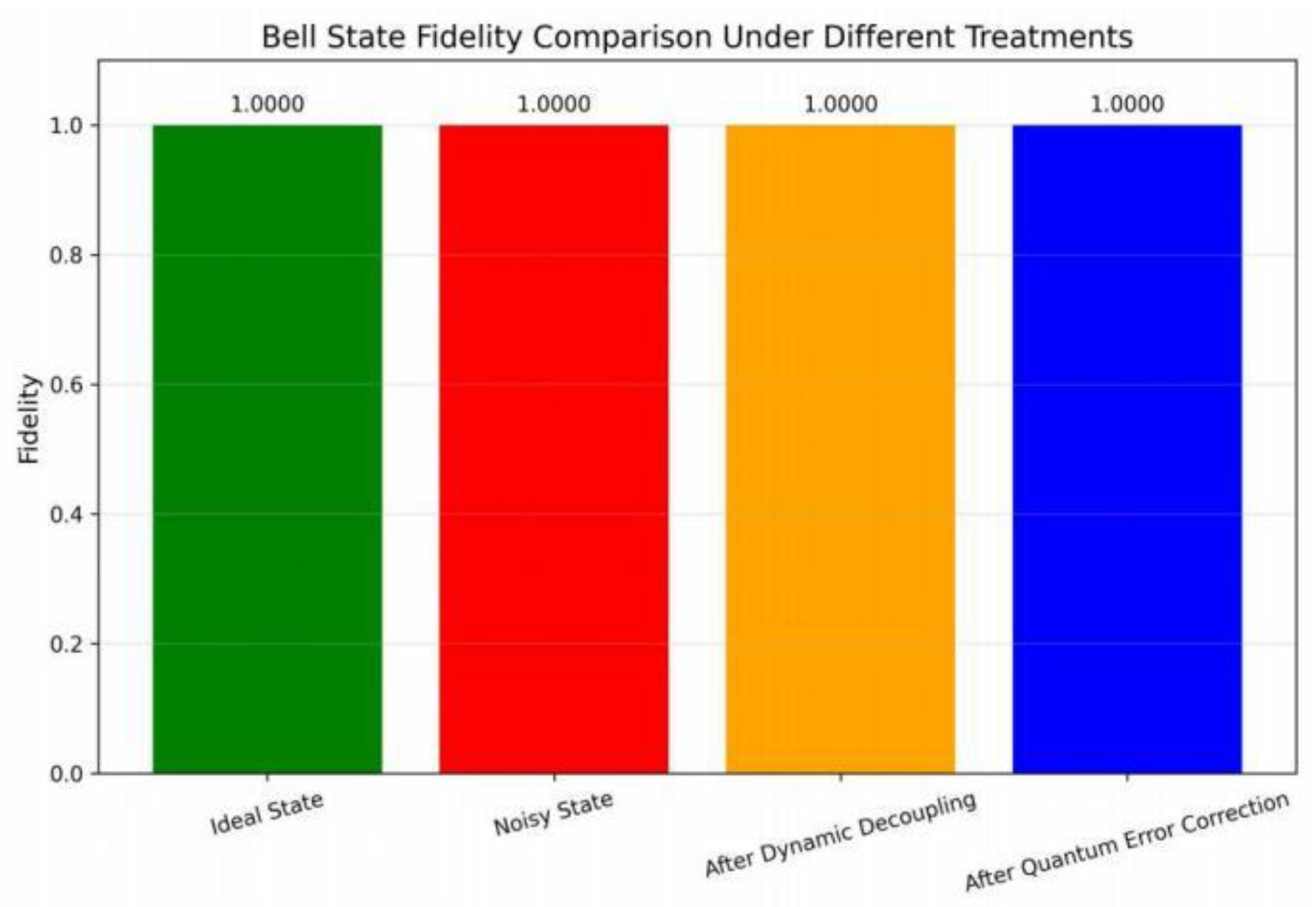

Table 1.
Comparison of count distribution before and after disturbance in Qiskit simulation under different measurement scales.
Table 1.
Comparison of count distribution before and after disturbance in Qiskit simulation under different measurement scales.
| Number of measurements (Qiskit shots) | processing method | |00〉 Proportion | |11〉 Proportion | Error state ratio | Error state reduction |
| 10000 (n=2) | Not disturbed | 37.20% | 38.29% | 24.51% | 98.3% (n=2) |
| After disturbance | 49.85% | 49.73% | 0.42% | ||
| 1000000 (n=2) | Not disturbed | 37.73% | 37.88% | 24.39% | 98.4% (n=2) |
| After disturbance | 49.92% | 49.68% | 0.40% |
Table 2.
Comparison of Bell state fidelity under different measurement scales (each condition was simulated twice).
Table 2.
Comparison of Bell state fidelity under different measurement scales (each condition was simulated twice).
| scheme | Integrity (10,000 measurements) | Integrity (measured in 100,000) |
| Ideal state (noiseless simulation) | 1.0000 | 1.0000 |
| After disturbance resistance treatment (simulated noise environment) | 1.0000 | 1.0000 |
| Dynamic decoupling (analog noise environment) | 1.0000 | 1.0000 |
| After quantum error correction (simulated noise environment) | 1.0000 | 1.0000 |
Table 3.
Complexity comparison of anti-jitter schemes (based on Qiskit statistics).
| scheme | Number of additional doors | Assisted qubit count |
| This article is divided into Qubit strategies | 4 (X doors) | 0 |
| Surface code error correction [9] | 30+ (multiple types of doors) | 11 |
| XY4 Dynamic Decoupling [8] | 8 (pulse gate) | 0 |
Disclaimer/Publisher’s Note: The statements, opinions and data contained in all publications are solely those of the individual author(s) and contributor(s) and not of MDPI and/or the editor(s). MDPI and/or the editor(s) disclaim responsibility for any injury to people or property resulting from any ideas, methods, instructions or products referred to in the content. |
© 2025 by the authors. Licensee MDPI, Basel, Switzerland. This article is an open access article distributed under the terms and conditions of the Creative Commons Attribution (CC BY) license (http://creativecommons.org/licenses/by/4.0/).
Copyright: This open access article is published under a Creative Commons CC BY 4.0 license, which permit the free download, distribution, and reuse, provided that the author and preprint are cited in any reuse.


