Submitted:
26 September 2025
Posted:
29 September 2025
You are already at the latest version
Abstract
The parasitic currents issue arises at high frequency operation of induction motor. The flow of parasitic currents is the main cause of premature deterioration of winding insulation and damage to the ball bearing. In order to comprehend the effect of electromagnetic interference (EMI) an equivalent per-phase model of an induction motor should be investigated at higher frequencies. The per-phase induction motor mathematical model of induction motor drive for common mode (CM) configuration is developed to perform high frequency analysis for drive operation. The high frequency per phase induction motor model MATLAB model is developed to generate the transfer function of IM and generate bode plots for CM and differential mode (DM) impedance configuration for high frequency analysis. The induction motor typical frequency response without considerations of stray and parasitic effects is presented for normal behavior of IM. In order to verify the simulated impedance parameters of 0.3 kW and 38kW induction motor with stray and parasitic components. High frequency response for magnitude and phase response is generated and compared to analyze per phase induction motor model performance before and after resonance frequencies. The comparison of CM and DM bode plots validates the dominance of inductance and parasitic capacitance before and after the occurrence of resonance frequency respectively.
Keywords:
High Frequency Induction Motor Analysis for Common Mode and Differential Mode Impedance Characteristics
1. Introduction
Induction motors (IMs) are known for high performance in diverse industrial environments. The IM’s smooth operational characteristics without core or insulation damage are maintained by thermal protection and winding failure associated with motor components maintaining better dynamic performance [1]. Variable frequency drive-based IM applications are common in daily life applications. IMs exhibit exceptional reliability, robustness, and efficient operation in complex situations. These motors are subjected to Electro-Magnetic Interference (EMI) issues by higher frequency content due to instant transients in power supply parameters. The pulses generated after pulse width modulation (PWM) contribute to leakage and bearing currents as well as the machine’s body losses. The transients in voltage cause insulation failure, which can cause short circuit currents leading to contact failures [2,3]. Furthermore, the EMI waves are capable to affect the machine drive components and severely affect the performance of key components involved in feedback loops [4]. Motor bearings are distressed by the flow of leakage current due to winding insulation failure caused by stress developed by voltage transient, this, in turn, reduces the life span and reliable operation of the motor drive [5,6]. The high frequency models used to represent the behavior of machines are electrical equivalent circuits. The circuits are developed to mirror the machine behavior at higher frequency bands. These equivalent models are based on impedance values depending upon resistance and reactance offered by resistance (R), inductance (L), and conductance (C) of the stator, rotor, and magnetizing components respectively. The value of RLC based impedance can be measured by calculations based on motor design parameters for the EMI testing environment [7,8,9,10,11,12,13]. The resistance and inductance of the motor remain constant at lower frequencies, Hence the value remains the same for lower frequency bands. Whereas, at higher frequencies, the value of stator, rotor, and magnetizing impedance deviates from existing values. This behavior is observed due to the dependency of reactance in both inductance or capacitance forms on the frequency of supply parameters. The EMI standards are measured over the frequency band of 150 KHz to 30 MHz [12,13]. Moreover, models operating beyond 10 MHz are deviating from the accurate handling of design parameters [14,15,16].
The high frequency phenomenon lies in the magnetic core of IMs that can significantly influence the motor’s performance. The rotor and stator magnetic cores are laminated with steel sheets to reduce the flow of eddy currents generated during alternating magnetic fields created by alternating supply voltages. But, after a certain frequency range, the eddy current factor becomes prominent despite the presence of insulation, as the skin depth of conducting path becomes smaller than the overall thickness of the insulation sheet. Therefore, the eddy currents induced by magnetic field create a shielding effect in the lamination sheet which in turn changes the value of inductance [17,18].
The impact of parasitic capacitance at low frequency is neglectable as the impedance offered in the form of capacitive reactance is large. Whereas, if the frequency rises then capacitive reactance decreases. It creates new current paths inside the motor body due to the lower impedance offered by parasitic capacitors. Therefore, due to higher frequency multiple current paths are created due to lesser opposition offered by parasitic capacitance [14,17,19]. There are multiple ways to visualize the behavior of IM over a wide range of frequencies. The equivalent circuit model of IM for electromagnetic field analysis is derived from the design parameters of the motor by using the finite element method (FEM). The FEM analysis is capable to find the resistance, inductance, and capacitance of each turn in winding [20,21,22,23,24]. On the other hand, lumped parameter model (LPM) measures the parameters of IM experimentally. This approach demands the physical presence of the motor for measurements, hence it cannot facilitate the design stage as a manufactured motor cannot be altered instantly [25,26,27,28]. Some hybrid approaches are used for the measurement of constant motor parameters [19,29].
Measurement based approach takes CM and DM impedance and calculates Impedance parameters from measured values to model a high frequency IM. While, obtaining CM and DM impedance curves concerning frequency separate connection schemes are employed [7,8,25,26,28,30].
The paper objectives presented in this paper are as follows:
- To develop high frequency model of induction motor per phase model for common mode and differential mode impedance characteristics.
- The High frequency model of the IM drive for common mode characteristics was tested by the POWERSIM simulation model.
- Analyze common mode and differential mode impedance (magnitude and phase) frequency response bode plots of high frequency induction motors.
The paper was arranged in the following order: Section 2 highlights the background of studies related to the high frequency behavior of induction motors and state-of-the-art simulation approaches to visualize the variation of IM behavior at higher frequencies. Section 3 gives a detailed parameter as well as an FFT analysis of high frequency IM drive model simulated in POWERSIM for various electrical parameters. Section 4 presents two different high frequency IM Matlab models that are investigated for CM and DM impedance characteristics at higher frequencies. Both models were analyzed under the same equivalent per phase high frequency CM and DM impedance models. Conclusion and prospects are discussed in Section 5.
2. Materials and Methods
An induction motor (IM) can withstand interference from the outside environment and has a reasonable price tag. By tracking a rotating magnetic field, the IM’s rotor induces a voltage in the rotor bar that is proportional to the rotation's angular velocity [31]. The adjustable speed drive (ASD) inverter of the IM switches multiples times on or off, it subjects the power lines and the IM to a significant dV/dt. High-frequency currents can flow as a result of these voltage variations, both between the motor's windings and the ground through stray capacitive contacts creating common mode currents and across the phases of the motor. Common mode current is a source of electromagnetic interference and can cause other problems by coupling to surrounding systems. It causes the bearings to wear down, the lubrication to evaporate, and the conduit housing the three-phase wires to overheat. It also decreases the motor insulation lifespan [32].
High-frequency (HF) voltage injection is used to estimate the rotor winding temperature in current-regulated squirrel-cage induction motors (IMs). The test result displays that the estimator works well under the initial situation, load variations, and cooling state of the motor. The newly presented technique not only helps in predicting faults but it can also be used to remedy the effects of changes in an IM controller [33]. To generate the switching pulses, hysteresis current control (HCC) is used. HCC is more popular due to its simplicity, remarkable stability, lack of tracking error, very fast transient response, inherent limiting maximum current, and intrinsic robustness to variations in load parameters. It is the job of the hysteretic controller to send the appropriate switching signal to the VSI to deliver the reference current if the error is greater than either the higher or lower hysteresis limit [34].
The digital adaptive hysteresis current control is particularly simple and effective at controlling the switching frequency and the phase of the inverter's voltage pulses, which are naturally centered in the modulation period. This mode of regulation has proven better switching frequency and phase control [35]. A high frequency power converter module for recharging batteries is developed for use in plug-in hybrid electric vehicle (EV) systems. The suggested 3-phase semi-controlled rectification topology significantly reduces switching and conduction losses in contrast to the fully-controlled topology. Under varying situations, such as a shift in the dc-reference step and load changes, a swift control dynamic response of 0.1 seconds is observed. The collected information supports the validity of the proposed system for PHEVs [36]. Current and vibration transients are examined using cutting-edge signal processing techniques including the discrete wavelet transform (DWT) and a multiresolution Fourier transform (MFT). Vibrational transients are recorded during the load withdrawal process provide evidence that it occurs at a very high frequency. As the defect grows worse, frequency of the defective gear mesh gain energy, but a large amount of impact energy is also generated in low-frequency regions. Load release in current transients, on the other hand, happens at low frequencies, albeit a tiny transient might be observed in high-frequency regions due to faulty equipment [37].
Hysteresis controllers are used in many applications due to their high dynamic responsiveness, ease of setup, and high overload current safety. Hysteresis current control has been proven to be efficient for two-level inverters. Dynamic responsiveness, implementation simplicity, and current overload prevention are all strong suits of the multiband hysteresis current controller (MHCC). As the torque output of a three-stage brushless DC motor drive is smoothed down as much as possible by the design [38]. The DTC method is used to minimize torque ripples and control the switching frequency of a motor. The simulations are ranging from transient to steady-state activities. At a constant reference speed, an induction motor's transient response is examined at starting, accelerating, and slowing down phases [39]. Space-vector pulse-width modulation-based switching sequence for a three-level neutral-point clamped inverter (SV-PWM) helps to reduce the number of switching sequences and keeps the difference in voltage between the two dc-link capacitors at the desired level, both are improvements over the standard SV-PWM strategy. In addition, the technique aids in maintaining the specified voltage differential between the capacitors. There is a limited range of switching patterns that are employed uniformly across all industries. It keeps the system's switching frequency constant [40].
A user-friendly high frequency model of IM presents the variation in parameters for EMI examination. The circuit elements are determined by a multilayer perceptron neural network for time-domain simulation of variable frequency drive systems [41]. An IM drive high frequency performance is observed for EMI for a frequency range of 100 Hz to 30 Mhz. The high frequency model can be modified to predict the EMC problems and implements adequate filter operation to enhance susceptibility in cable-fed motor-drive system [42,43]. High frequency induction machine model parameters are converted into state-space model illustration and motor impedance is estimated for a frequency range of 150 kHz to 30 MHz [44]. Common mode and bearing currents supplied by the inverter are investigated for the Spice-based high frequency electric motor model. The simulated model is suitable to present model behavior for a frequency range of 50 kHz to 3 MHz [45].
In an induction machine drive system, Inverter’s switching operation generates a higher rate of change in voltage, this abrupt change is the main cause of leakage and bearing currents, due to the formation of stray and parasitic capacitances in high frequency drive operation. The analysis of high frequency model is beneficial to evaluate model performance under EMC recommendations [46]. The motor speed and bearing-key frequency are used to detect the failure and guide for diagnosis of the electric motor. Estimation algorithms are used for the detection of bearing faults during high frequency demodulation. The motor vibration model is simulated to generate vibration data. The algorithm performance is validated by comparison with the vibration dataset [47]. The star-connected high-frequency model of IM with defined parameters is being analyzed for EMI analysis. The IM model consists of a simple structure and nine circuit elements per phase. The element values are calculated by using a multilayer perceptron (MLP) neural network, with phase-to-frame motor impedance acquired for model training. The analysis suggests that common mode and differential mode impedance are accurately measured for the frequency range 150 kHz to 30 MHz [48]. IM high frequency model is developed to predict terminal overvoltage, common mode, and differential mode impedance of AC motor. The model is derived based on a mathematical model of IM’s transfer function simulated in Matlab to visualize the high frequency behavior of IM under the frequency range of 40 Hz to 110 MHz [49].
High frequency IM’s impedance is measured in CM and DM configurations. The impedance values are taken for state-space representation and the HF model structure is developed. The genetic algorithm is used for tuning real impedance as per the configuration of High frequency IM model [50]. IM models powered by inverters ranging from 1.5 and 240 kW are modeled for the calculation of common-mode current and bearing voltage to investigate bearing failure. The model parameters are calculated to accurately predict IM’s bearing fault [51]. A six-port star and delta model of three-phase IM is derived from CM and DM equivalent RLC impedances. The model predicts impedance with high precision to 100 MHz and highlights six port CM and DM multi-mode noise [52].
The high frequency behavior of IM over a wider frequency range from 10 Hz to 10 MHz is examined. The equivalent circuit model is presented for bearing, common mode, and differential mode models developed under a single universal three-phase model [53]. The high frequency IM models are examined to summarize motor behavior at high frequency. The model forecasts EMI noise disturbances in motor drive applications [54]. The IM model parameters are determined by the least-square curve fitting approach. Magnitude and phase plots of CM and DM impedance curves are used to calculate IM model parameters. This approach indicates the suitable value of high frequency parameters concerning the model and size of the motor [55]. In the IM-based variable speed drive powered by PWM, impedance parameters are measured by RLC bridges in the laboratory, the parameters are measured at rated and high frequencies to monitor the effect of EMI in CM and DM configurations [56]. The high frequency motor impedance of stator winding is measured by per unit length (PUL) transmission line equivalent circuit. The PUL circuit consists of both high and low-frequency components, able to measure high frequency behavior of IM. Moreover, the same procedure can be employed to simulate high frequency motor’s magnitude and phase response accurately [57].
2.1. High Frequency Model for Induction Motor
The asynchronous motor, often known as an induction motor, is the type of motor that is most commonly used in commercial settings. The proposed models are developed by the calculation of the CM and DM impedances. The impedance model is employed to get a behavioral interpretation of the induction machine.
Electromagnetic interference (EMI) can be broken down into two distinct types: common mode interference (CM) and differential mode interference (DM). Motor impedance analysis requires the simultaneous observation of two sets of curves, one for the common mode and one for the differential mode, revealing the variations in motor impedance concerning frequency. An electric motor model at high frequency can be broken down into three main parts. These include inductance, losses, and stray capacitance between the windings and the stator. The key difficulty is an analysis of high dv/dt between the motor's terminals in Figure 1, which is caused by a common mode current generated by high-speed switching devices such as insulated gate bipolar transistors (IGBTs). The switching time and dv/dt are controlled by the IGBTs and their gate drivers [58,59].
The equivalent per-phase model of high frequency IM is presented in Figure 2.
Where,
Ld : Phase Leakage Inductance
R : Winding Resistance
Re : Eddy current resistance inside the magnetic core and motor frame
Cp : Turn-to-turn distributive coupling capacitance
Cg : Winding to turn distributive coupling capacitance
The high frequency three-phase model of an induction motor consists of three differential mode impedances denoted by ZDM, as well as three common mode impedances denoted by ZCM, all of which are connected to the ground terminal. Figure 2 shows per phase common mode impedance of high frequency induction motor model.
The following equations (1-5) are used to derive the common mode impedance of induction motor:
An equivalent per-phase circuit for a differential mode induction motor is presented in Figure 3. The following equations (6-10) are used to derive the differential mode impedance of induction motor:
Figure 4 presents the arrangement of motor terminals for the measurement of CM and DM impedance. The impedance is representing CM impedance and is serving as DM impedance. The phase resistance R is much smaller than the reactance of the leakage inductance L throughout the high frequency range. For this reason, the stator resistance will be ignored in all subsequent analyses. Both the ZCM and ZDM impedances can be simplified in equations (11-12) as follows:
2. Simulation of High Frequency Induction Motor Drive
A high frequency induction motor drive model based on an IGBT inverter is being analyzed in POWERSIM. The three-phase windings are connected as a Y-network as shown in Figure 5. Phase A, B, and C stator winding terminals are placed at nodes a, b, and c, respectively. Node n is the neutral point in a circuit, while the comm terminal is the common connection for a common-mode circuit. The mechanical shaft’s node houses the shaft's connection terminal. Parameters associated with high frequency responses are intended to be used for analyzing transient responses caused by the reflecting effect. Iron losses, Re, are caused by eddy currents in the magnetic core. The composite circuit of Rt, Lt, and Ct captures the second resonance in the frequency response. The skin effect and the inter-turn capacitance of the stator winding contributed to the development of second resonance. Parasitic components of each phase and the stator neutral relative to the motor frame (common point) are represented graphically by the Rg and Cg network. The dissipative effect is denoted by Rg, and the winding-to-ground capacitance is denoted by Cg.
The high frequency Induction Motor parameters are:
- Rs: Stator Resistance;
- Ls: Stator winding leakage inductance;
- Rr: Rotor winding resistance with respect to stator side;
- Lr: Rotor winding leakage inductance with respect to stator side;
- Lm: Magnetizing inductance;
- P: Total number of poles;
- J: Moment of inertia
High frequency model EMC parameters are:
- Cg: Winding to ground capacitance;
- Rg: Resistance due to motor frame;
- Re: Eddy current resistance in the motor core;
- Rt: Skin effect resistance at high-frequency;
- Lt: Skin effect inductance at high-frequency;
- Ct: Skin effect capacitance at high frequency;
Common mode electromagnetic interference (EMI) is produced on the three-phase output lines of a power inverter as a result of hard switching with higher change in voltage concerning time, it is dependent on the rise time of IGBTs and the system voltage. Due to the existence of parasitic components and operational factors, electromagnetic compatibility (EMC) issues become easily apparent. The high frequency IM drive model in Figure 6 is used to analyze the EMI effect caused by the inverter, AC cable, and induction motor at higher frequencies. While, Le represents the emitter’s parasitic inductance, and Cch represents the stray capacitance between the collector terminal and the grounded heatsink of each IGBT. Table 1 presents the parameters considered for the high frequency model.
The three-phase voltage supply is rectified from three phase diode bridge rectifier. Then the rectified output is applied on a three-phase IGBT inverter for a three-phase high frequency induction motor supply. The switching operation of the IGBT inverter is controlled by comparing the sinusoidal wave voltage source with a triangular wave voltage source.
The comparison generates pulses for IGBT switches. The pulses are applied directly to IGBT numbers 1, 3, and 5. Whereas, then inverted pulses are applied on IGBT numbers 4, 6, and 2 respectively.
3. Results and Discussion
The simulation of high frequency induction motor drive model is implemented with stray capacitance and parasitic impedance to visualize high frequency behavior of the induction motor connected in a common mode configuration. Figure 7a shows the existence of high-frequency transients in the common-mode current due to the presence of stray capacitance and parasitic inductance connected with six IGBT switches of three phase inverter. The common-mode current is taken by adding stray capacitance currents from upper and lower switches connected as a pair to even and odd values. The current waveform is further investigated in Figure 7b by taking the Fast Fourier Transform (FFT) of common mode current signal frequency analysis till megahertz frequency. The FFT analysis interprets multiple peaks presenting high frequency components in the current signal. The log scale enables visualization of the high frequency range to highlight the model performance under EMI effects caused by high frequency components introduced in the high frequency induction motor drive model. The waveform indicates the occurrence of high frequency content in current taken from inverter switches.
Figure 8a shows the terminal voltage Van applied at terminal A of high frequency induction motor drive. While Figure 8b presents an FFT analysis of terminal voltage (Van). Figure 9a displays phase-phase voltage Vab and Figure 9b is an FFT analysis of phase-phase voltage (Vab). Figure 10a compares carrier and modulation waves to generate upper output level and lower output level signals respectively. Whereas, Figure 10b highlights the FFT analysis used to indicate the fundamental frequency and harmonic frequency of both waves. Figure 11a presents a three-phase current supplied to the induction motor drive. Figure 11b compares FFT analysis of frequency harmonics for a three-phase current supply fed by an IGBT inverter.
4. Discussion of High Frequency IM Impedance
The high-frequency 50 Hp IM model has been visualized by performing frequency domain studies by developing the MATLAB program. Figure 12 presents the frequency response of the induction motor without considering EMC compatibility specifications. The switching operation performed in power devices in the inverter is the main cause of the abrupt change in voltage of the induction motor. As a result of this voltage variation, high-frequency differential mode currents flow between the motor phases due to the emergence of parasitic capacitance, while high-frequency common mode currents flow across the motor windings and the ground by means of stray capacitance. The common mode and differential mode characteristics of induction motor high frequency models presented in Figure 2 and Figure 3 have been validated by generating magnitude and phase plots in the frequency domain. The simulation results of CM and DM magnitude and phase response of 0.3 kW IM are presented in Figure 13 and Figure 14. Table 2 presents high frequency parameters of 0.3 kW IM presented in [60] Whereas 38 kW IM magnitude and phase frequency response of CM and DM impedance characteristics are displayed in Figure 15 and Figure 16.
Figure 13 CM bode plot indicates that a pole is located at the origin and two complex conjugate poles are located at the same distance on the imaginary axis. Moreover, two complex conjugate zeros are contributing to the frequency response of impedance in equation 11. The natural frequencies f1 and f2 are representing zeros and poles in equations (13-14).
The parameters in Table 3 are taken from high frequency induction motor model connected in a common mode configuration with stray and parasitic components in POWERSIM. The induction motor parameters are further matched with the 38 kW IM model in Simulink MATLAB. The common mode impedance bode plots of Figure 13 and Figure 15 indicate that the reactance of capacitor Cg dominates with the rise in frequency and it decreases linearly at a rate of -20dB per decade as frequency increases concerning the logarithmic scale. Until it reaches the first resonance point where the phase angle equals -90 degrees. Identical behavior is observed in Figure 13 and Figure 15 for the first resonant point f1 occurrence at -90 degrees.
The differential mode impedance bode plots in Figure 14 and Figure 16 indicate the dominance of inductive behavior with a rise of +20 dB in magnitude plot per decade till before resonant frequency point f1, while the phase plot indicates an angle of +90 degrees. At resonant frequency point f1, the inductive reactance of the inductor (L) becomes equal to the sum of capacitive reactance (Cp + Cg). With further upsurge in frequency the capacitive reactance of decays further until it becomes equal to the magnitude of the reactance of inductor (L) where second resonant frequency point f2 occurs. At this point, the reactance of both the capacitive and inductive sides becomes equal and cancels out each other.
After the second resonance frequency point f2 the parasitic capacitive reactance starts dominating and increases at a rate of -20 dB per decade. Whereas phase angle suddenly
reaches -90 degrees due to the dominance of parasitic capacitance after an increase in frequency beyond the second resonance frequency. One zero and two poles that are complex conjugates of each other constitute the differential mode impedance. Figure 14 and Figure 16 show good resemblance in simulated magnitude and phase frequency response behavior. The common mode impedance has two separate characteristic frequencies, based on the characteristic frequency of the magnitude. The first frequency f1, is the natural frequency of the common mode impedance Zpg numerator that occurs at the lowest impedance in the magnitude curve. The second frequency f2, is accomplished when the inductive and capacitive impedances in equation 14 are equal. The denominator of equation 14 specifies the differential mode resonance impedance. After crossing the second resonance frequency parasitic capacitance dominates for higher frequencies.
5. Conclusions
The study presents an equivalent per-phase mathematical model of induction motor for high frequency analysis of electrical parameters. The high frequency induction motor drive model is being analyzed for the effects of stray and parasitic by consideration of electrical parameters with FFT analysis. A correlation was found between computed models of 0.3 kW and 38 kW IM for frequency response curves. The proposed models are simulated by MATLAB program to visualize impedance characteristics beyond megahertz frequencies. The variation of common mode and differential mode impedance of IM models is quite comparable to each other. This research work provides a worthwhile visualization of EMI analysis for the design and modeling of induction motor drives at higher frequencies, in future EMI filters can be designed based on the high frequency behavior of induction motor drives.
Author Contributions
Conceptualization, H.S and G.A.H; methodology, N.H, M.S.S and Z.A.A.; software, M.S.S. and H.S; validation. K.I and H.S; formal analysis, M.S.S and G.A.H.; investigation, N.H, H.S and M.S.S.; resources, Z.R, Z.A.A.; data curation, Z.A A.; writing—original draft preparation, HS and K.I; writing—review and editing, Z.R, GAH; M.S.S- visualization, H.S.; supervision, K.I.; project administration, K.I, Z.A.A.; funding acquisition, G.A.H. All authors have read and agreed to the published version of the manuscript.”
Funding
This research received no external funding
Data Availability Statement
Data is included in the manuscript.
Acknowledgments
The author would like to thank their affiliated universities for supporting this research.
Conflicts of Interest
The authors declare no conflict of interest.
References
- Shen, Z.; Jiang, D.; Zou, T.; Qu, R. Dual-Segment Three-Phase PMSM with Dual Inverters for Leakage Current and Common-Mode EMI Reduction. IEEE Trans. Power Electron. 2019, 34, 5606–5619. [CrossRef]
- Mazurck, P.; Michalski, A.; Swiatck, H.; Mazzetti, C.; Flisowski, Z. Hazard for insulation and relevant emc problems due to voltages in circuits of motor supply by pwm converters. In Proceedings of the 2003 IEEE Bologna Power Tech Conference Proceedings, Bologna, Italy, 23–26 June 2003; Volume 2, pp. 728–732.
- Ferreira, F.J.; Trovão, J.P.; De Almeida, A.T. Motor bearings and insulation system condition diagnosis by means of common-mode currents and shaft-ground voltage correlation. In Proceedings of the 2008 International Conference on Electrical Machines, ICEM’08, Vilamoura, Portugal, 6–9 September 2008; pp. 1–6.
- Spadacini, G.; Grassi, F.; Pignari, S.A. Conducted emissions in the powertrain of electric vehicles. IEEE Int. Symp. Electromagn. Compat. 2017, 69, 1–15. [CrossRef]
- Robles, E.; Fernandez, M.; Andreu, J.; Ibarra, E.; Ugalde, U. Advanced power inverter topologies and modulation techniques for common-mode voltage elimination in electric motor drive systems. Renew. Sustain. Energy Rev. 2021, 140, 110746. [CrossRef]
- Plazenet, T.; Boileau, T.; Caironi, C.; Nahid-Mobarakeh, B. An overview of shaft voltages and bearing currents in rotating machines. In Proceedings of the IEEE Industry Application Society, 52nd Annual Meeting: IAS 2016, Portland, OR, USA, 2–6 October 2016; pp. 1–8.
- Zare, F. Practical approach to model electric motors for electromagnetic interference and shaft voltage analysis. IET Electr. Power Appl. 2010, 4, 727–738. [CrossRef]
- Miloudi, H.; Bendaoud, A.; Miloudi, M.; Dickmann, S.; Schenke, S. Common mode and differential mode characteristics of AC motor for EMC analysis. In Proceedings of the IEEE International Symposium on Electromagnetic Compatibility, Wroclaw, Poland, 5–9 September 2016; pp. 765–769.
- Lee, S.; Liu, M.; Lee, W.; Sarlioglu, B. Comparison of High-Frequency Impedance of AC Machines with Circumferential and Toroidal Winding Topologies for SiC MOSFET Machine Drives. In Proceedings of the 2020 IEEE Energy Conversion Congress and Exposition (ECCE), Detroit, MI, USA, 11–15 October 2020; pp. 3572–3579.
- Xiong, Y.; Li, X.; Li, Y.; Zhao, X. A high-frequency motor model constructed based on vector fitting method. In Proceedings of the 2019 Joint International Symposium on Electromagnetic Compatibility, Sapporo and Asia-Pacific International Symposium on Electromagnetic Compatibility, EMC Sapporo/APEMC 2019, Sapporo, Japan, 3–7 June 2019; pp. 191–194.
- Xiong, Y.; Chen, X.; Zong, L.; Li, X.; Nie, X.; Yang, G.; Zhao, X. An Electric Drive System Modelling Method Based on Module Behavior. In Proceedings of the 2019 International Conference on Microwave and Millimeter Wave Technology, ICMMT 2019—Proceedings, Guangzhou, China, 19–22 May 2019; pp. 1–3.
- Gries, M.A.; Mirafzal, B. Permanent magnet motor-drive frequency response characterization for transient phenomena and conducted EMI analysis. In Proceedings of the 2008 Twenty-Third Annual IEEE Applied Power Electronics Conference and Exposition, Austin, TX, USA, 24–28 February 2008; pp. 1767–1775.
- Schinkel, M.; Weber, S.; Guttowski, S.; John, W.; Reichl, H. Efficient HF Modeling and Model Parameterization of Induction Machines for Time and Frequency Domain Simulations. In Proceedings of the Twenty-First Annual IEEE Applied Power Electronics Conference and Exposition, 2006. APEC ’06, Dallas, TX, USA, 19–23 March 2006; Volume 2006, pp. 1181–1186.
- Zhang, D.; Kong, L.; Wen, X. High frequency model of interior permanent magnet motor for EMI analysis. In Proceedings of the 2014 IEEE Conference and Expo Transportation Electrification Asia-Pacific (ITEC Asia-Pacific), Beijing, China, 31 August–3 September 2014; pp. 1–6.
- Radja, N.; Rachek, M.; Larbi, S.N. Improved RLMC-Circuit HF-Dependent Parameters Using FE-EM Computation Dedicated to Predict Fast Transient Voltage Along Insulated Windings. IEEE Trans. Electromagn. Compat. 2019, 61, 301–308. [CrossRef]
- Magdun, O.; Binder, A.; Purcarea, C.; Rocks, A. High-frequency induction machine models for calculation and prediction of common mode stator ground currents in electric drive systems. In Proceedings of the 2009 13th European Conference on Power Electronics and Applications, EPE ’09, Barcelona, Spain, 8–10 September 2009; pp. 1–8.
- Heidler, B.; Brune, K.; Doppelbauer, M. High-frequency model and parameter identification of electrical machines using numerical simulations. In Proceedings of the 2015 IEEE International Electric Machines & Drives Conference (IEMDC), Coeur d’Alene, ID, USA, 10–13 May 2015; pp. 1221–1227.
- Mohammed, O.A.; Ganu, S.; Liu, S.; Liu, Z.; Abed, N. Study of high frequency model of permanent magnet motor. In Proceedings of the 2005 IEEE International Conference on Electric Machines and Drives, San Antonio, TX, USA, 15 May 2005; pp. 622–627.
- Jaritz, M.; Jaeger, C.; Bucher, M.; Smajic, J.; Vukovic, D.; Blume, S. An Improved Model for Circulating Bearing Currents in Inverter-Fed AC Machines. In Proceedings of the 2019 IEEE International Conference on Industrial Technology (ICIT), Melbourne, VIC, Australia, 13–15 February 2019; pp. 225–230.
- De Gersem, H.; Henze, O.; Weiland, T.; Binder, A. Transmission-line modelling of wave propagation effects in machine windings. In Proceedings of the 2008 13th International Power Electronics and Motion Control Conference, Poznan, Poland, 1–3 September 2008; pp. 2385–2392.
- Zhang, J.; Xu, W.; Gao, C.; Wang, S.; Qiu, J.; Zhu, J.G.; Guo, Y. Analysis of inter-turn insulation of high voltage electrical machine by using multi-conductor transmission line model. IEEE Trans. Magn. 2013, 49, 1905–1908. [CrossRef]
- Sarrio, J.E.R.; Martis, C.; Chauvicourt, F. Numerical Computation of Parasitic Slot Capacitances in Electrical Machines. In Proceedings of the 2020 International Conference and Exposition on Electrical And Power Engineering (EPE), Iasi, Romania, 22–23 October 2020; pp. 146–150.
- Birnkammer, F.; Chen, J.; Pinhal, D.B.; Gerling, D. Influence of the Modeling Depth and Voltage Level on the AC Losses in Parallel Conductors of a Permanent Magnet Synchronous Machine. IEEE Trans. Appl. Supercond. 2018, 28, 1–5.
- Ruiz-Sarrio, J.E.; Chauvicourt, F.; Gyselinck, J.; Martis, C. High-Frequency Modelling of Electrical Machine Windings Using Numerical Methods. In Proceedings of the 2021 IEEE International Electric Machines & Drives Conference (IEMDC), Hartford, CT, USA, 17–20 May 2021; pp. 1–7. [CrossRef.
- Vidmar, G.; Miljavec, D. A Universal High-Frequency Three-Phase Electric-Motor Model Suitable for the Delta- and Star-Winding Connections. IEEE Trans. Power Electron. 2015, 30, 4365–4376. [CrossRef]
- Mohammadi-Rostam, M.; Shahabi, M.; Shayegani-Akmal, A.A. High frequency lumped parameter model for EMI problems and over voltage analysis of Induction motor. J. Electr. Eng. 2013, 13, 278–283.
- Gavrilenko, V.; Gavrilenko, V. Characterization of Winding Insulation of Electrical Machines Fed by Voltage Waves with High dV/dt. Ph.D. Thesis, Université Paris-Saclay, Université polytechnique de Tomsk (Russie), Gif-sur-Yvette, France, 2020.
- Wu, Y.; Bi, C.; Jia, K.; Jin, D.; Li, H.; Yao, W.; Liu, G. High-frequency modelling of permanent magnet synchronous motor with star connection. IET Electr. Power Appl. 2018, 12, 539–546.
- Volpe, G.; Popescu, M.; Marignetti, F.; Goss, J. AC winding losses in automotive traction e-machines: A new hybrid calculation method. In Proceedings of the 2019 IEEE International Electric Machines and Drives Conference, IEMDC 2019, San Diego, CA, USA, 12–15 May 2019; pp. 2115–2119.
- Toulabi, M.S.; Wang, L.; Bieber, L.; Filizadeh, S.; Jatskevich, J. A Universal High-Frequency Induction Machine Model and Characterization Method for Arbitrary Stator Winding Connections. IEEE Trans. Energy Convers. 2019, 34, 1164–1177. [CrossRef]
- S. B. Monge, J. Bordonau, D. Boroyevich, and S. Somavilla, “The nearest three virtual space vector PWM—A modulation for the comprehensive neutral point balancing in the three-level NPC inverter,” IEEE Power Electron. Lett., vol. 2, no. 1, pp. 11–15, Mar. 2004. [CrossRef]
- S. Rachev, and L. Dimitrov, Study on electric vehicle induction motor drive. Proceedings of 13th International Conference ‘Research and Development in Mechanical Industry’ RaDMI 2013, Kopaonik, Serbia, 2013, vol. 2, pp. 920–926. ISBN 978-86-6075-043-5.
- Cho, K. R., & Seok, J. K. (2009). Induction motor rotor temperature estimation based on a high-frequency model of a rotor bar. IEEE Transactions on Industry Applications, 45(4), 1267-1275.
- Vahedi, H., Sheikholeslami, A., Tavakoli Bina, M., & Vahedi, M. (2011). Review and simulation of fixed and adaptive hysteresis current control considering switching losses and high-frequency harmonics. Advances in power electronics, 2011. [CrossRef]
- Buso, S., Fasolo, S., Malesani, L., & Mattavelli, P. (2000). A dead-beat adaptive hysteresis current control. IEEE Transactions on industry applications, 36(4), 1174-1180.
- Amin, M. M., & Mohammed, O. A. (2011, September). A three-phase high frequency semi-controlled battery charging power converter for plug-in hybrid electric vehicles. In 2011 IEEE Energy Conversion Congress and Exposition (pp. 2641-2648). IEEE.
- Kar, C., & Mohanty, A. R. (2008). Vibration and current transient monitoring for gearbox fault detection using multiresolution Fourier transform. Journal of Sound and Vibration, 311(1-2), 109-132.
- Raj, R. A., Shreelakshmi, M. P., & George, S. (2020, December). Multiband Hysteresis Current Controller for Three Level BLDC Motor Drive. In 2020 International Conference on Power, Instrumentation, Control and Computing (PICC) (pp. 1-6). IEEE.
- Ben Salem, F., & Feki, M. (2019). An Improved DTC Induction Motor for Electric Vehicle Propulsion: An Intention to Provide a Comfortable Ride. Solving Transport Problems: Towards Green Logistics, 185-201.
- Choudhury, A., Pillay, P., & Williamson, S. S. (2014). DC-link voltage balancing for a three-level electric vehicle traction inverter using an innovative switching sequence control scheme. IEEE Journal of Emerging and Selected Topics in Power Electronics, 2(2), 296-307. [CrossRef]
- Zhao, Z., Fan, F., Sun, Q., Tu, P., & See, K. Y. (2022, September). High-frequency modeling of induction motor using multilayer perceptron. In 2022 Asia-Pacific International Symposium on Electromagnetic Compatibility (APEMC) (pp. 222-224). IEEE.
- Mohammadi-Rostam, M., & Shahabi, M. (2016). Modeling induction motor for prediction of high frequency problems. Iranian Journal of Science and Technology, Transactions of Electrical Engineering, 40, 13-22.
- Mohammadi-Rostam, M., Shahabi, M., & Shayegani-Akmal, A. A. (2013). High frequency lumped parameter model for EMI problems and over voltage analysis of Induction motor. J. Electr. Eng, 13, 278-283.
- Degano, M., Zanchetta, P., Clare, J., & Empringham, L. (2010, July). HF induction motor modeling using genetic algorithms and experimental impedance measurement. In 2010 IEEE International Symposium on Industrial Electronics (pp. 1296-1301). IEEE.
- Cacciato, M., Consoli, A., Finocchiaro, L., & Testa, A. (2005, September). High frequency modeling of bearing currents and shaft voltage on electrical motors. In 2005 International Conference on Electrical Machines and Systems (Vol. 3, pp. 2065-2070). IEEE.
- Zare, F. (2008). High frequency model of an electric motor based on measurement results. Australian Journal of Electrical and Electronics Engineering, 4(1), 17-24.
- Ocak, H., & Loparo, K. A. (2004). Estimation of the running speed and bearing defect frequencies of an induction motor from vibration data. Mechanical systems and signal processing, 18(3), 515-533. [CrossRef]
- Zhao, Z., Fan, F., Sun, Q., Tu, P., & See, K. Y. (2022). High-Frequency Modeling of Star-Connected Induction Motors Using Multilayer Perceptron.
- Miloudi, H., Miloudi, M., Gourbi, A., Bermaki, M. H., Bendaoud, A., & Zeghoudi, A. (2022). A high-frequency modeling of AC motor in a frequency range from 40 Hz to 110 MHz. Electrical Engineering & Electromechanics, (6), 3-7.
- Degano, M., Zanchetta, P., Empringham, L., Lavopa, E., & Clare, J. (2012). HF induction motor modeling using automated experimental impedance measurement matching. IEEE Transactions on Industrial Electronics, 59(10), 3789-3796. [CrossRef]
- Magdun, O., & Binder, A. (2013). High-frequency induction machine modeling for common mode current and bearing voltage calculation. IEEE Transactions on Industry Applications, 50(3), 1780-1790.
- Karakaşlı, V., Gross, F., Braun, T., De Gersem, H., & Griepentrog, G. (2022). High-frequency modeling of delta-and star-connected induction motors. IEEE Transactions on Electromagnetic Compatibility, 64(5), 1533-1544.
- Mirafzal, B., Skibinski, G. L., Tallam, R. M., Schlegel, D. W., & Lukaszewski, R. A. (2007). Universal induction motor model with low-to-high frequency-response characteristics. IEEE Transactions on Industry Applications, 43(5), 1233-1246.
- Jia, K., Bohlin, G., Enohnyaket, M., & Thottappillil, R. (2013). Modelling an AC motor with high accuracy in a wide frequency range. IET Electric Power Applications, 7(2), 116-122. [CrossRef]
- Boglietti, A., Cavagnino, A., & Lazzari, M. (2007). Experimental high-frequency parameter identification of AC electrical motors. IEEE Transactions on Industry Applications, 43(1), 23-29.
- Riehl, R. R., & Ruppert Filho, E. (2007, October). A simplified method for determining the high frequency induction motor equivalent electrical circuit parameters to be used in EMI effect. In 2007 International Conference on Electrical Machines and Systems (ICEMS) (pp. 1244-1248). IEEE.
- Ryu, Y., Park, B. R., & Han, K. J. (2015). Estimation of high-frequency parameters of AC machine from transmission line model. IEEE Transactions on Magnetics, 51(3), 1-4. [CrossRef]
- Salahuddin, H., Imdad, K., Chaudhry, M. U., Iqbal, M. M., Bolshev, V., Hussain, A., ... & Jasiński, M. (2022). Electric Vehicle Transient Speed Control Based on Vector Control FM-PI Speed Controller for Induction Motor. Applied Sciences, 12(17), 8694. [CrossRef]
- Zare, F. (2006, November). Modelling of electric motors for electromagnetic compatibility analysis. In AUPEC 2006.
- Miloudi, H., Bendaoud, A., Miloudi, M., Dickmann, S., & Schenke, S. (2016, September). Common mode and differential mode characteristics of AC motor for EMC analysis. In 2016 International Symposium on Electromagnetic Compatibility-EMC EUROPE (pp. 765-769). IEEE.
Figure 1.
High frequency model of induction motor fed by inverter.
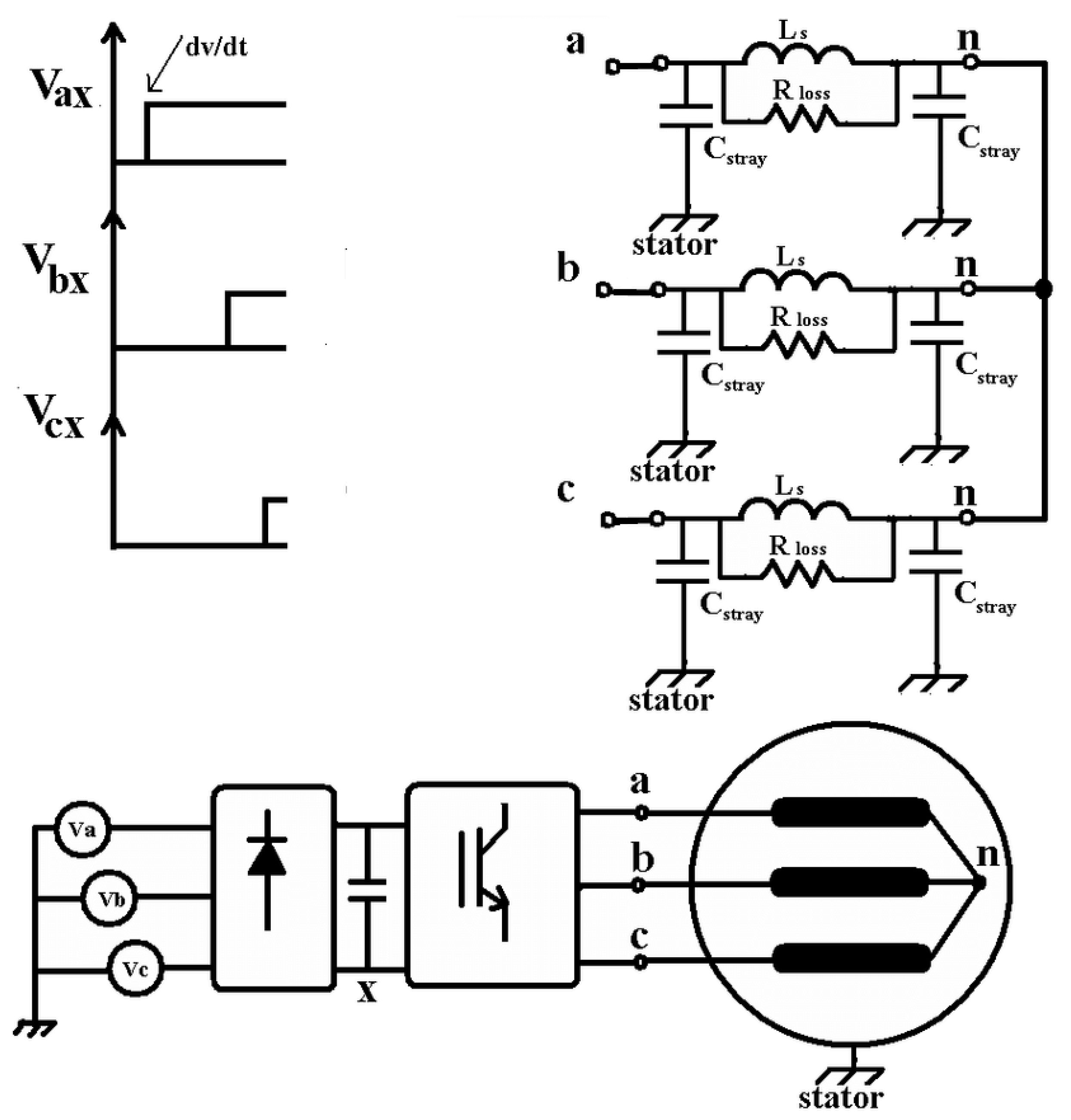
Figure 2.
Equivalent circuit per phase in high frequency IM model [60].
Figure 2.
Equivalent circuit per phase in high frequency IM model [60].
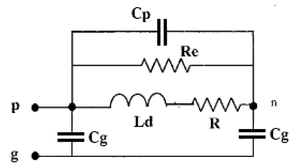
Figure 3.
Equivalent per phase circuit of differential mode impedance Zpp’.
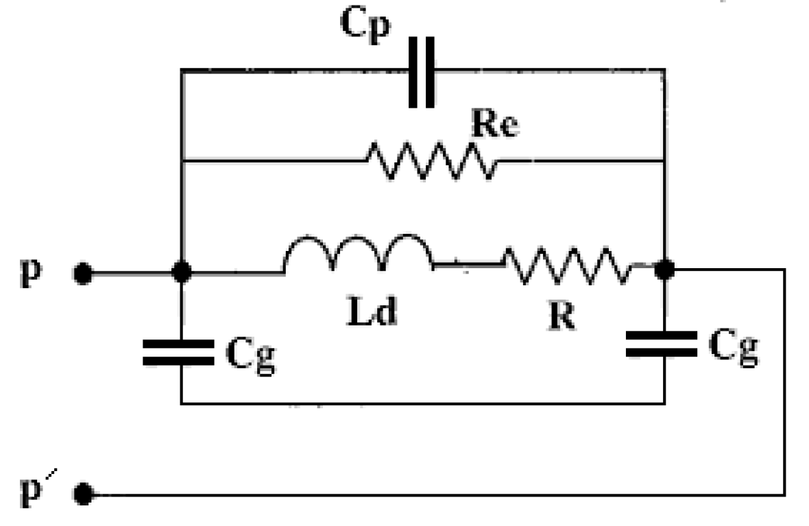
Figure 4.
Impedance analyzer connection diagram for CM and DM calculation.
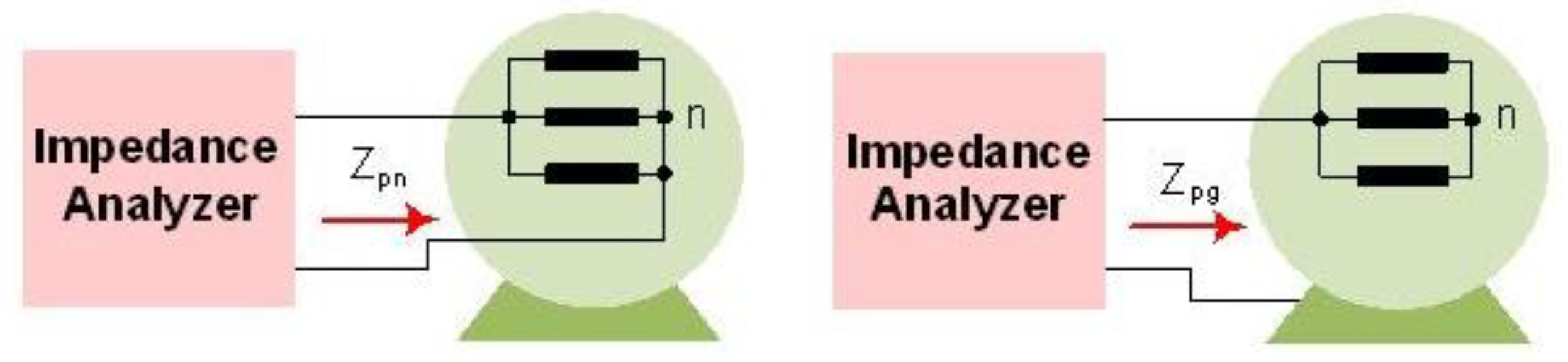
Figure 5.
Induction motor drive block for high frequency model (POWERSIM).
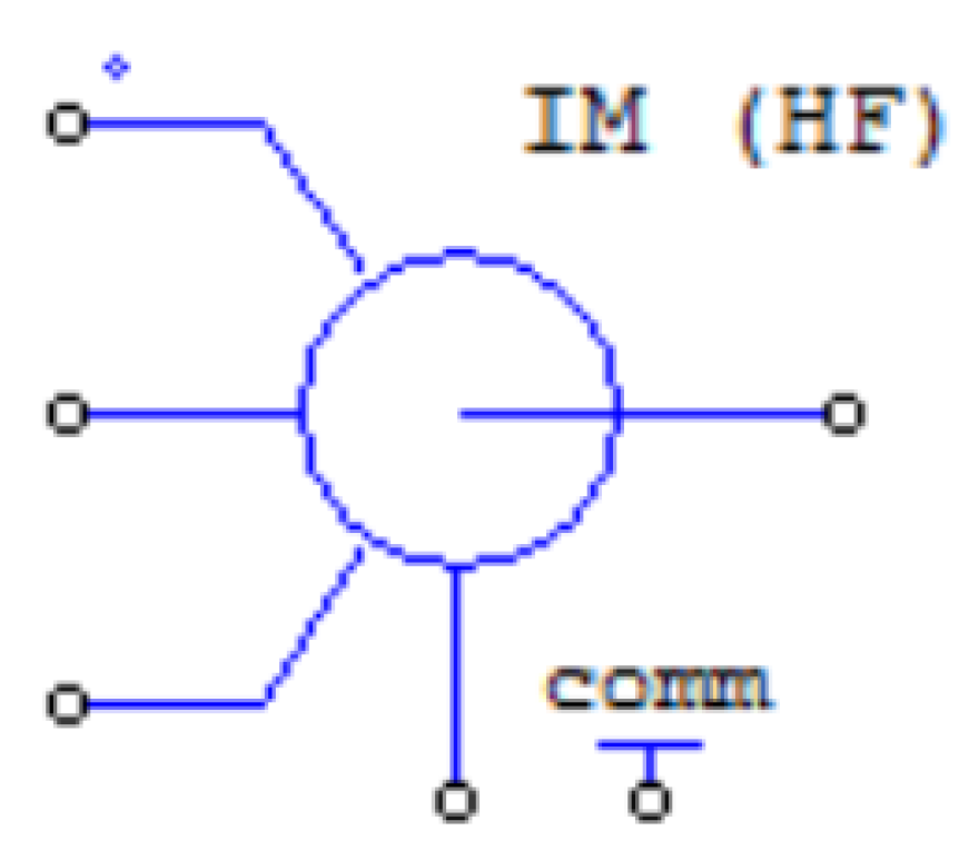
Figure 6.
Induction motor drive for high frequency EMC analysis (Parasitic inductance and stray capacitance).
Figure 6.
Induction motor drive for high frequency EMC analysis (Parasitic inductance and stray capacitance).
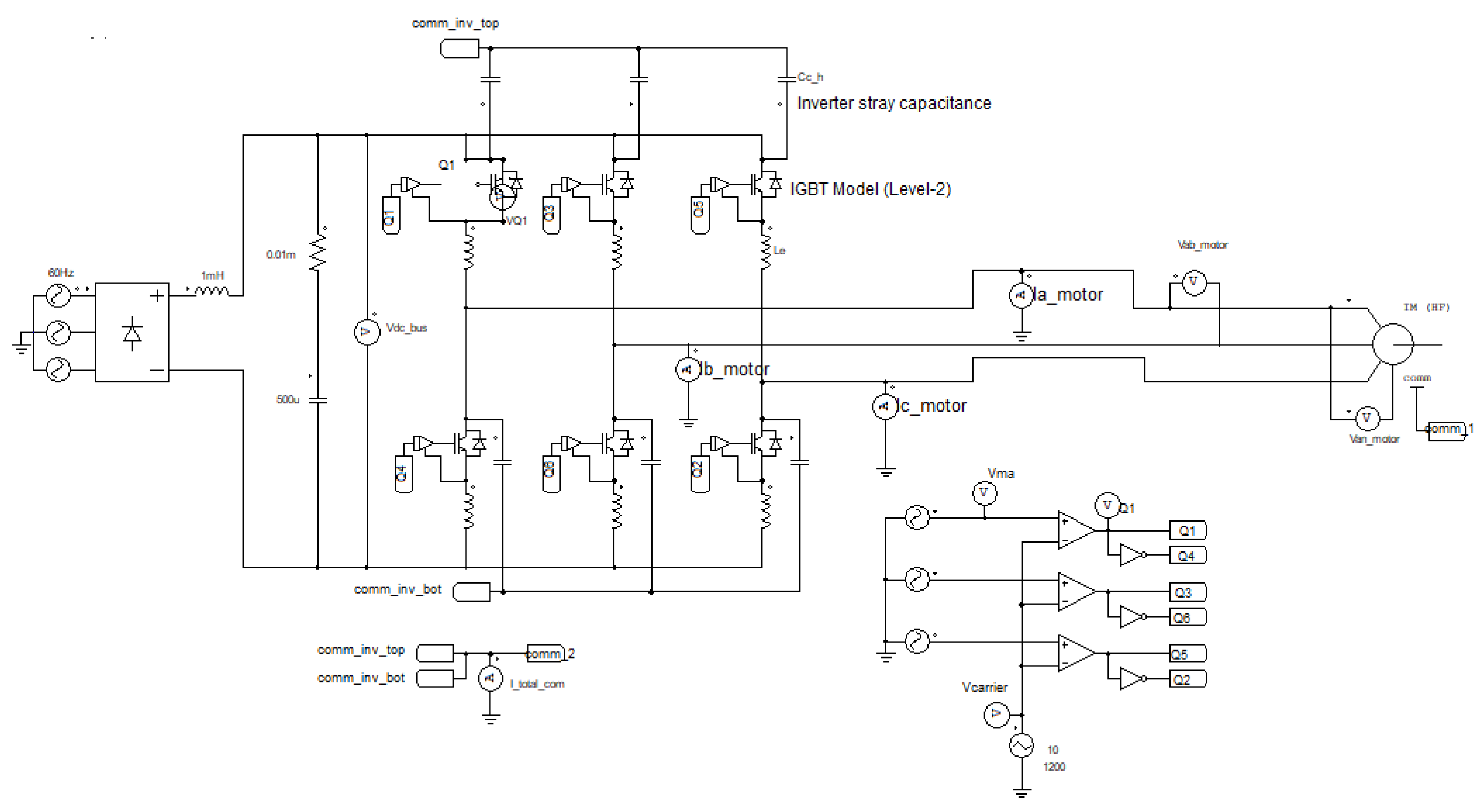
Figure 7.
(a). Induction motor drive high frequency model common mode inverter current. (b). FFT analysis of common mode inverter current.
Figure 7.
(a). Induction motor drive high frequency model common mode inverter current. (b). FFT analysis of common mode inverter current.
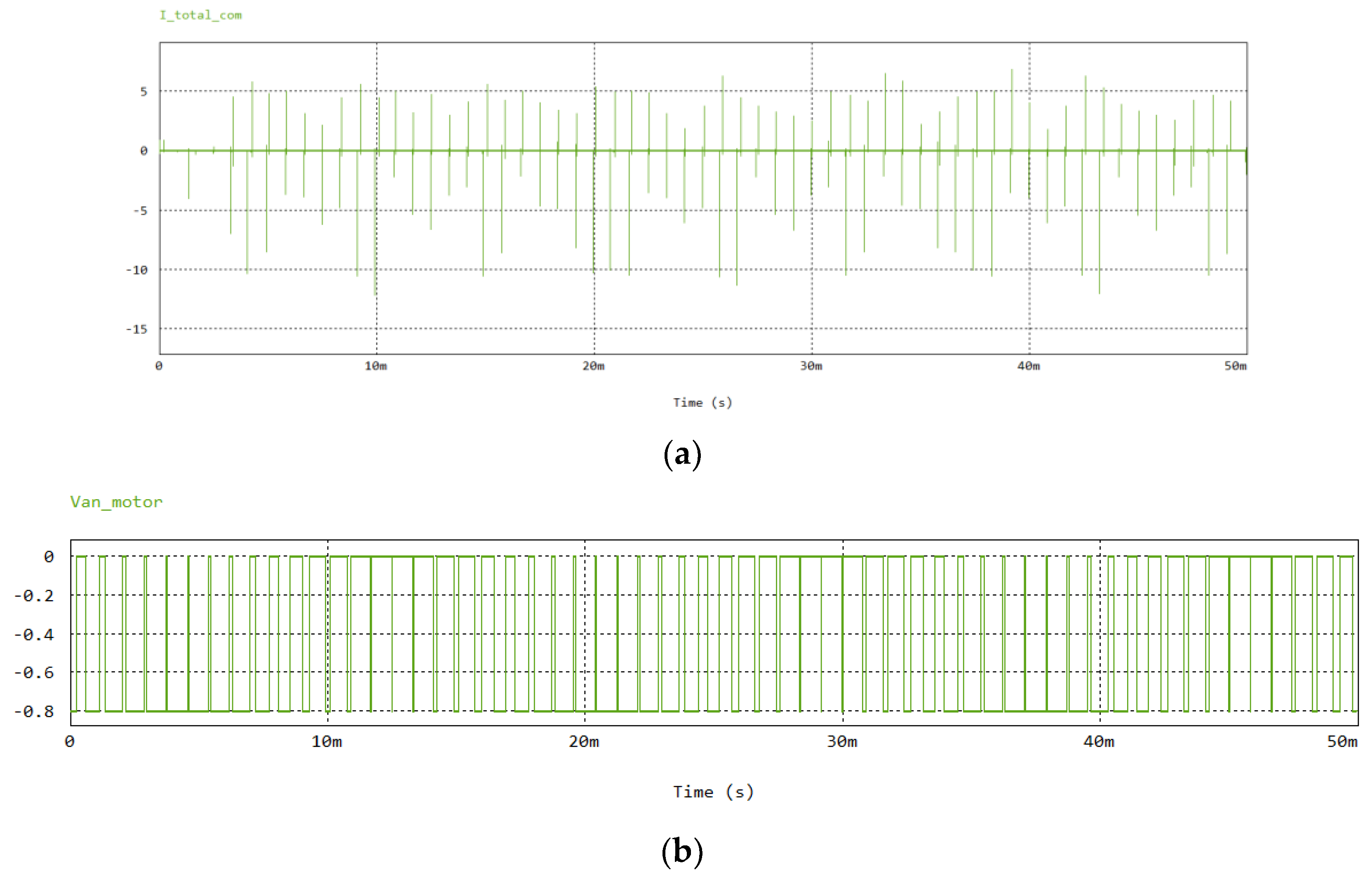
Figure 8.
(a). Induction motor drive terminal voltage (Van). FFT analysis of induction motor drive terminal voltage (Van).
Figure 8.
(a). Induction motor drive terminal voltage (Van). FFT analysis of induction motor drive terminal voltage (Van).
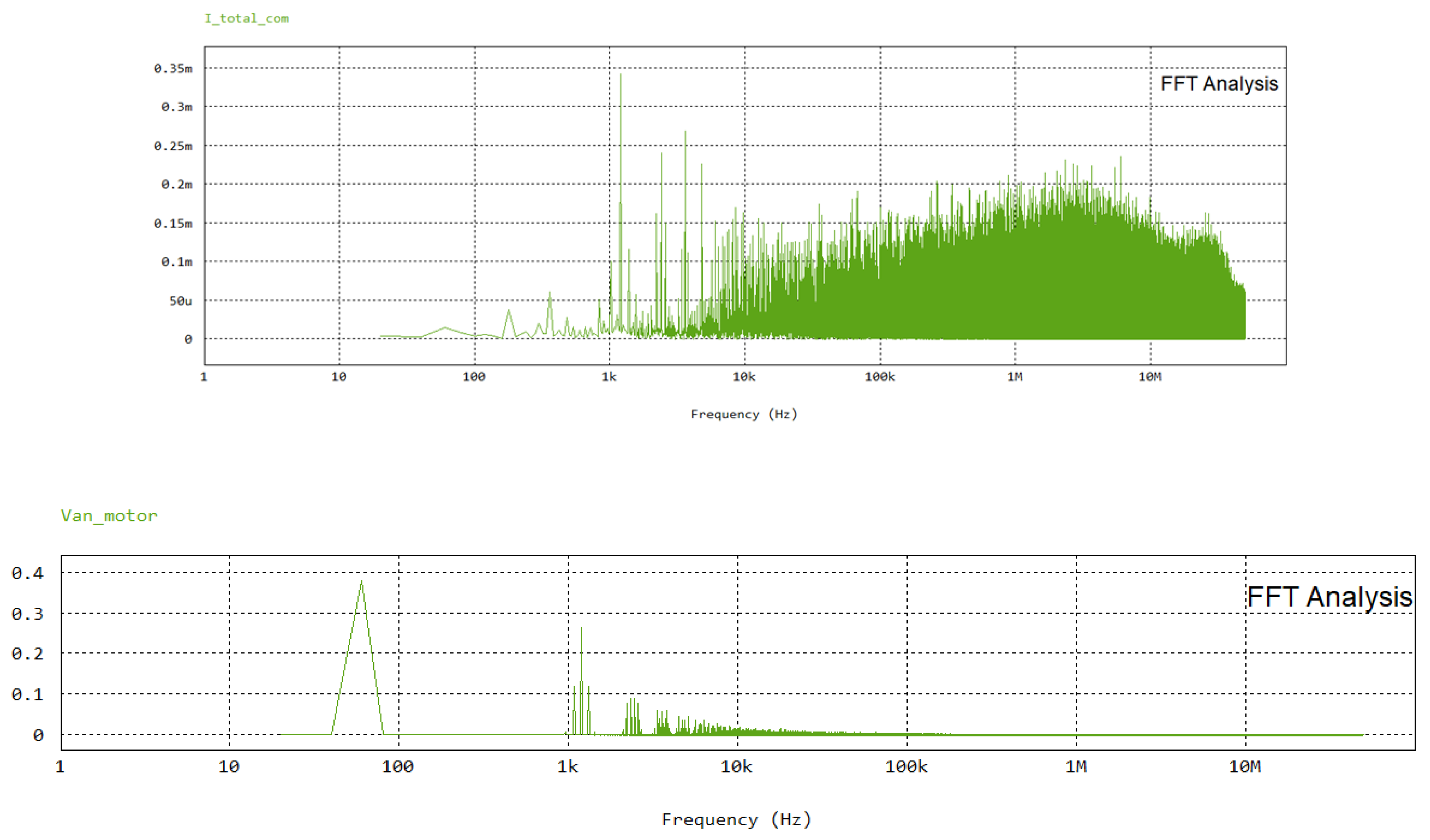
Figure 9.
Figure 9. (a). Induction motor drive phase-phase voltage (Vab). FFT analysis of induction motor drive phase-phase voltage (Vab).
Figure 9.
Figure 9. (a). Induction motor drive phase-phase voltage (Vab). FFT analysis of induction motor drive phase-phase voltage (Vab).
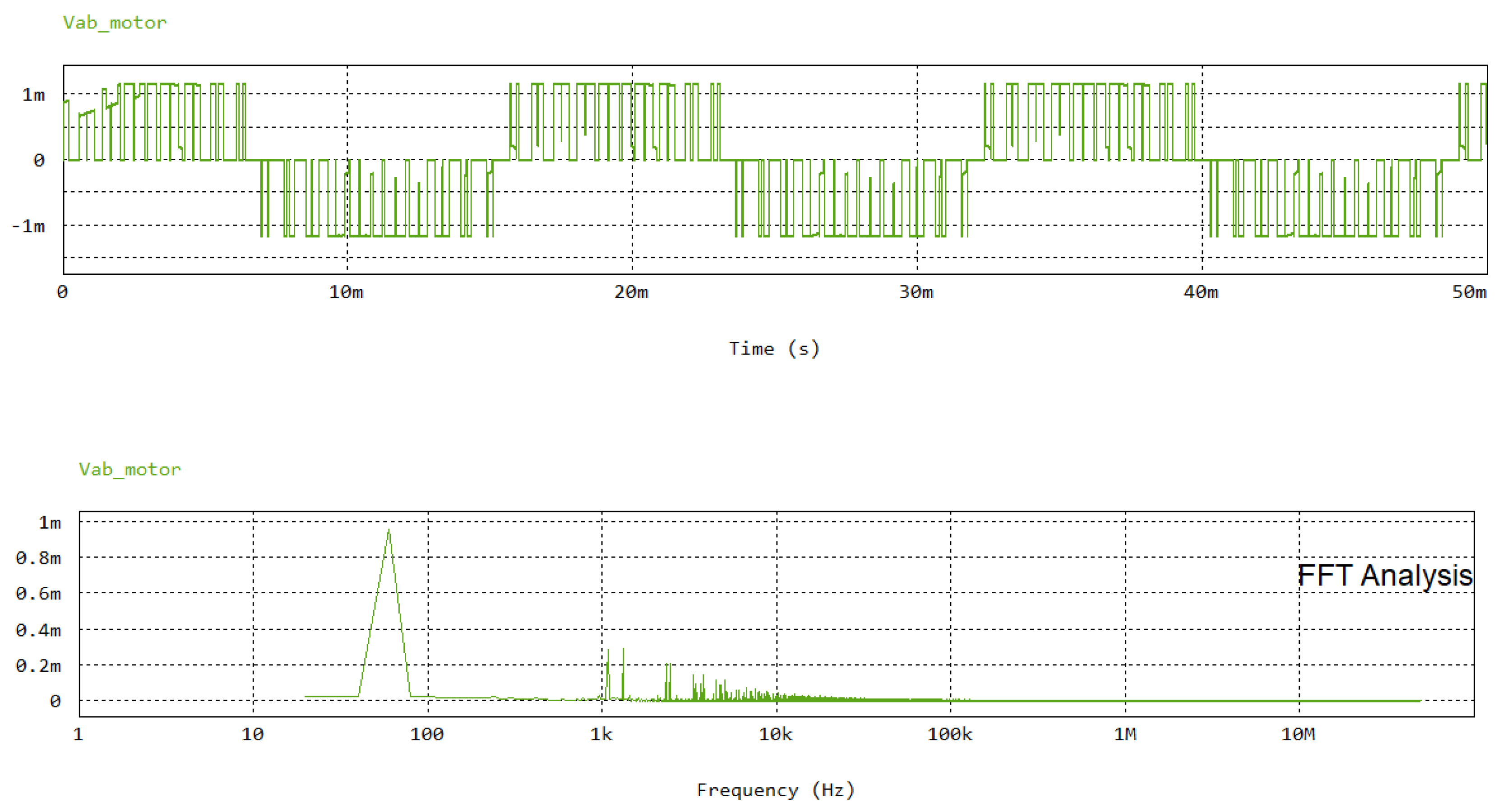
Figure 10.
Figure 10. (a). IGBT inverter switching cycle (Carrier and Modulation wave). FFT analysis of carrier and modulation wave.
Figure 10.
Figure 10. (a). IGBT inverter switching cycle (Carrier and Modulation wave). FFT analysis of carrier and modulation wave.
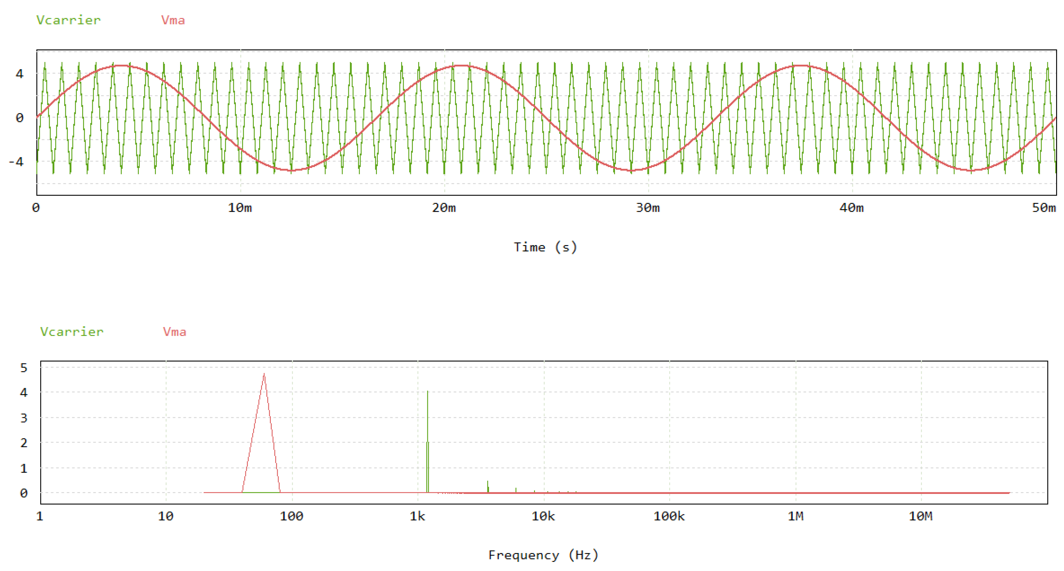
Figure 11.
(a). Three phase Induction motor drive current. FFT analysis of three phase Induction motor drive current.
Figure 11.
(a). Three phase Induction motor drive current. FFT analysis of three phase Induction motor drive current.
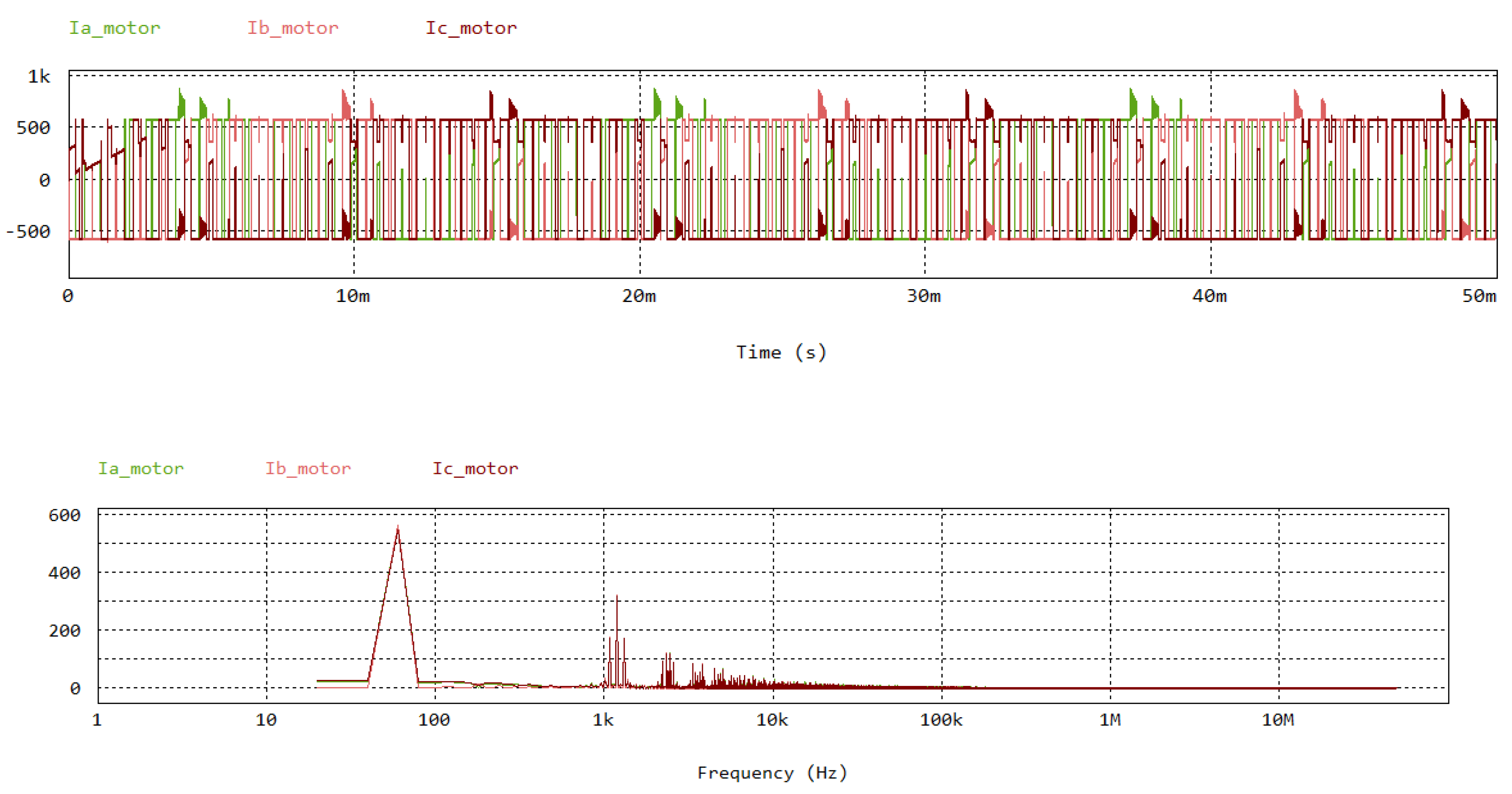
Figure 12.
Impedance magnitude and phase frequency response of 38 kW IM model.
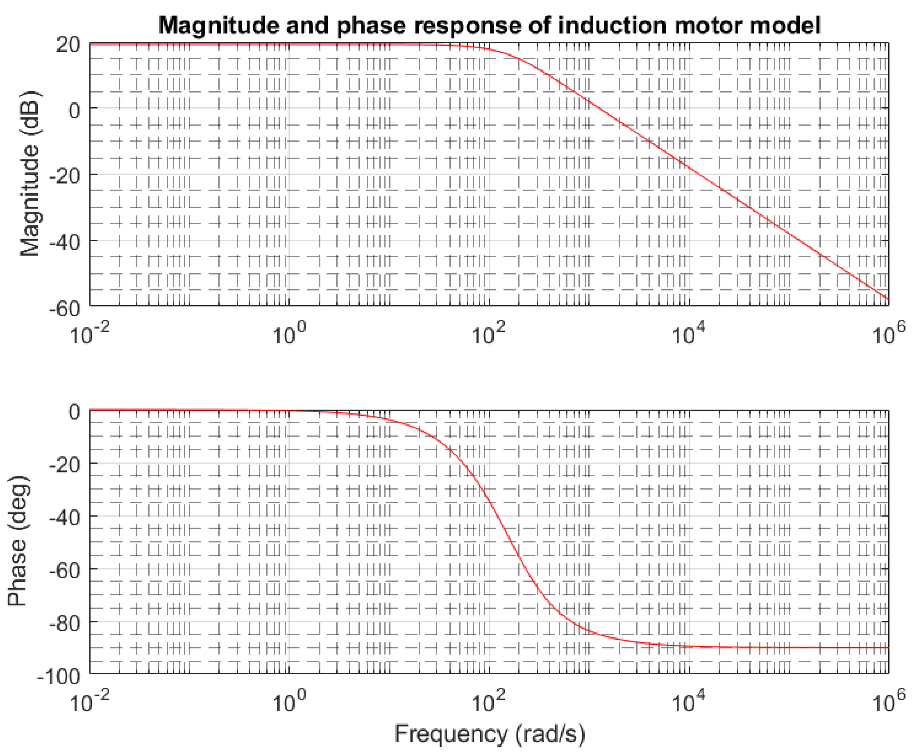
Figure 13.
Common mode impedance magnitude and phase frequency response of 0.3 kW IM model.
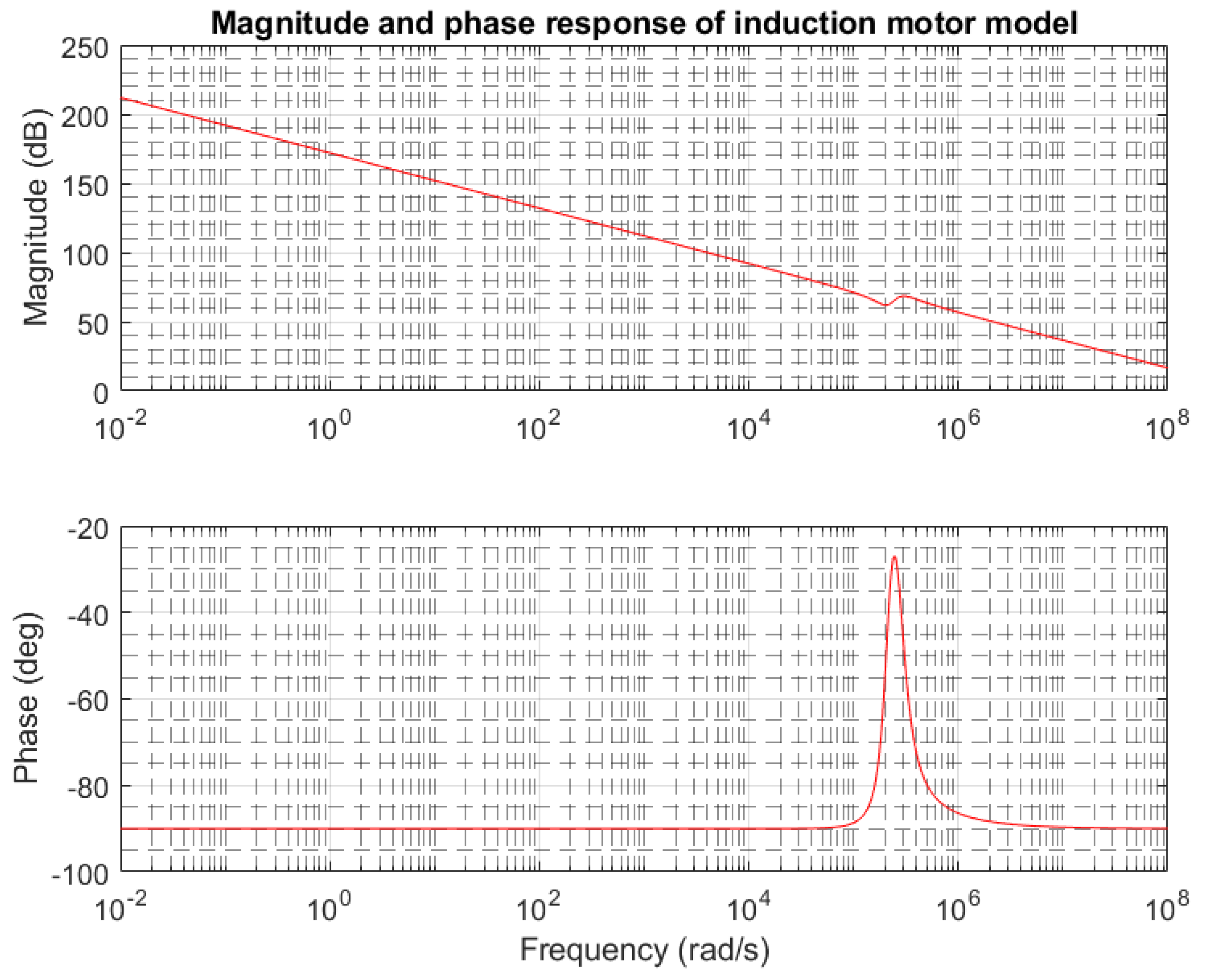
Figure 14.
Differential mode impedance magnitude and phase frequency response of 0.3 kW IM model.
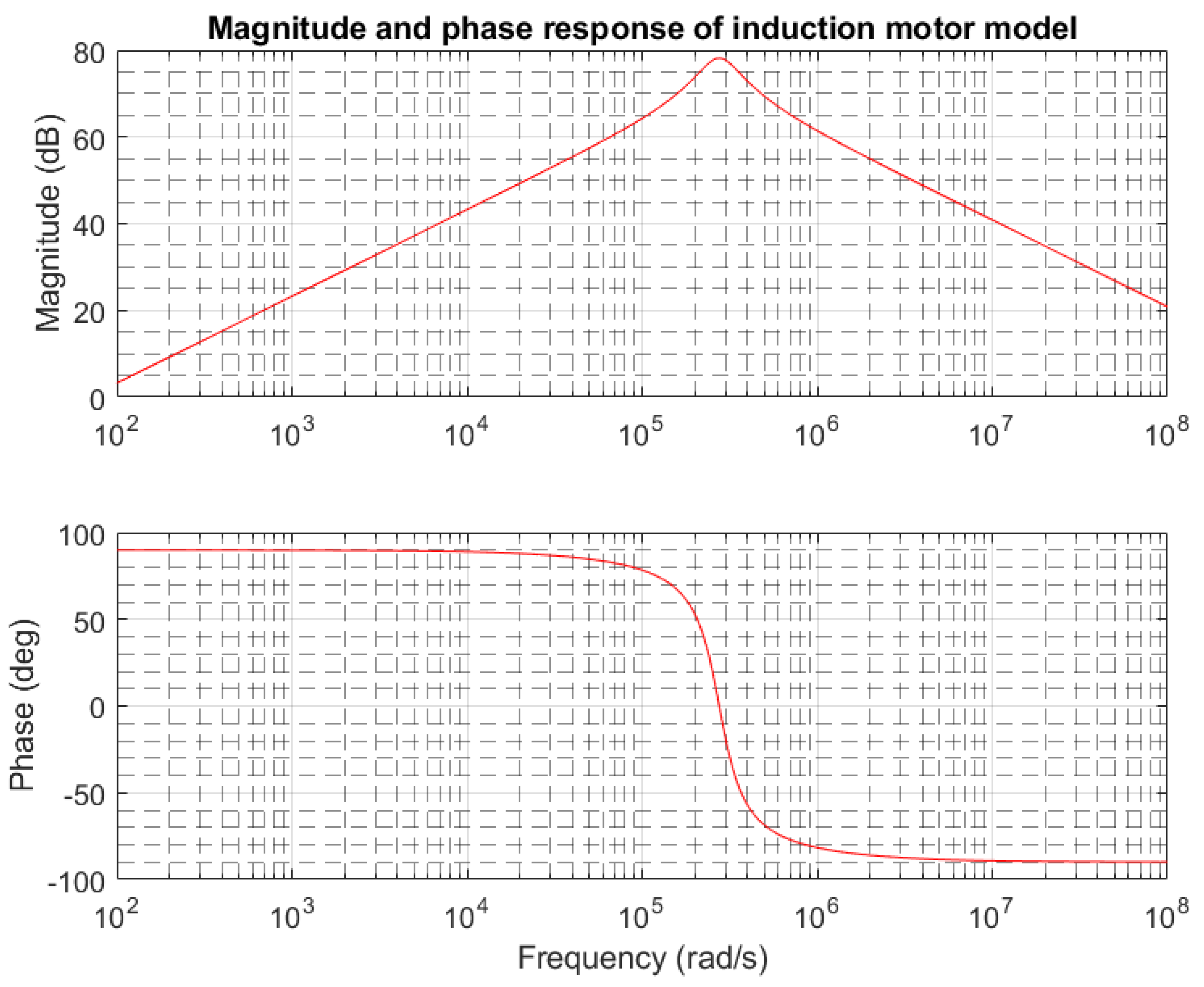
Figure 15.
Common mode impedance magnitude and phase frequency response of 38 kW IM model.
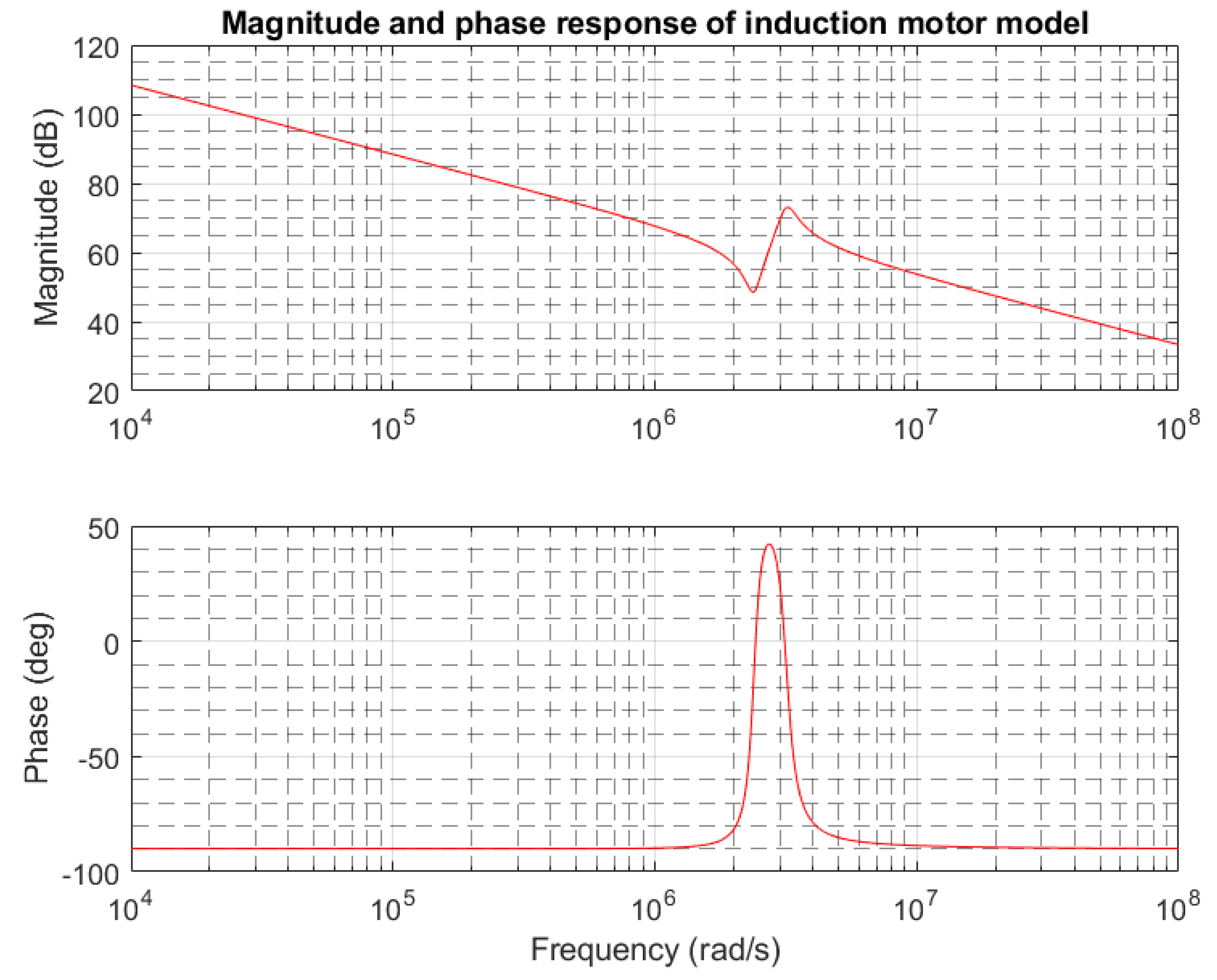
Figure 16.
Differential mode impedance magnitude and phase frequency response of 38 kW IM model.
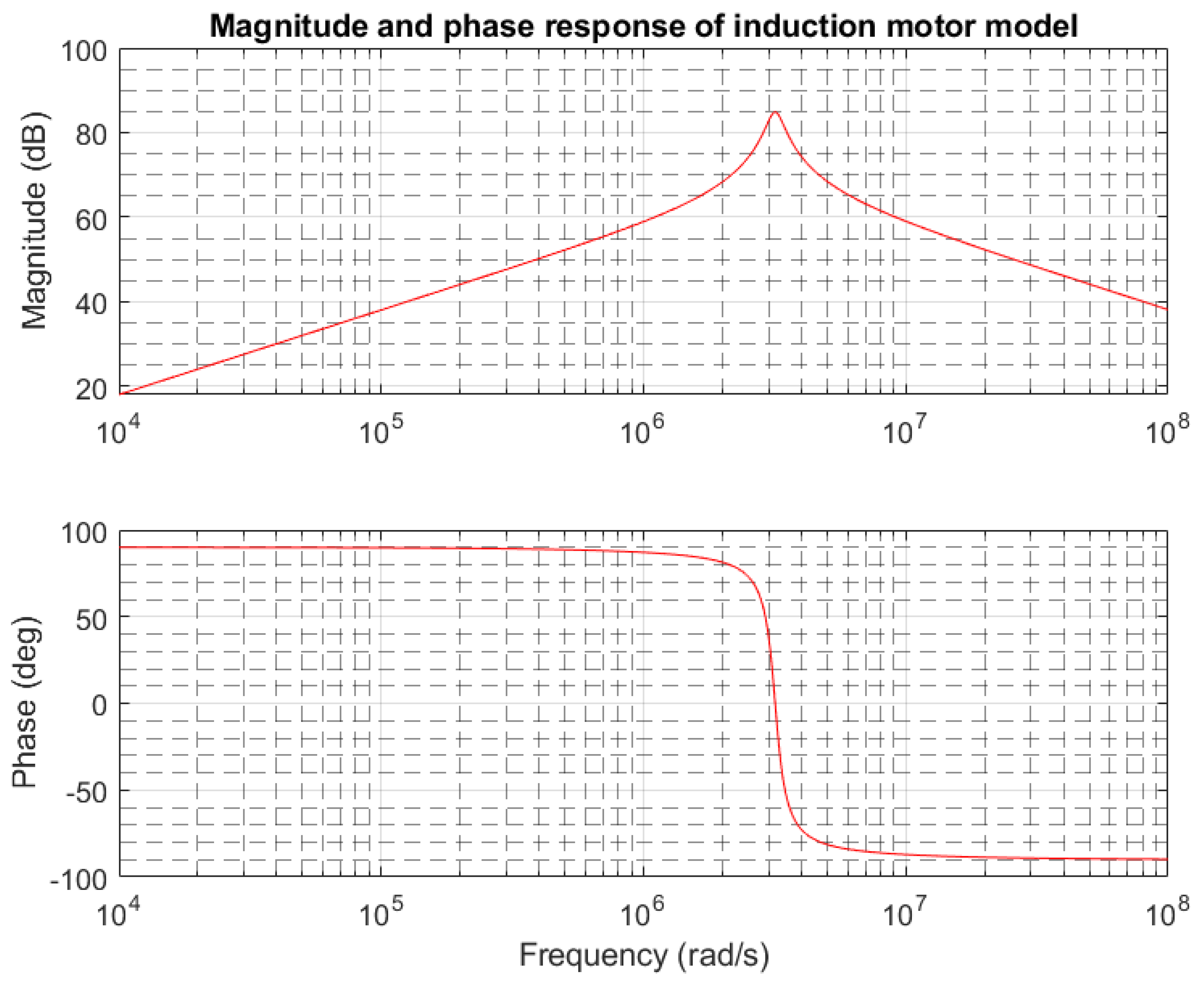

Table 1.
High frequency 38 kW induction motor drive model parameters.
| Symbol | Parameter | Value |
|---|---|---|
| Rs | Stator resistance | 0.087 |
| Ls | Stator leakage inductance | 0.8m |
| Rr | Rotor resistance | 0.227 |
| Lr | Rotor leakage inductance | 0.8m |
| Lm | Magnetizing inductance | 34.7m |
| P | No of poles | 4 |
| J | Moment of inertia | 1.662 |
| Cg | Winding to ground capacitance | 190p |
| Rg | Resistance due to motor frame | 1000k |
| Re | Eddy current resistance | 17.49k |
| Rt | Skin effect resistance | 0.324k |
| Lt | Skin effect inductance | 0.27m |
| Ct | Skin effect capacitance | 29p |
| Le | IGBT’s Emitter parasitic inductance | 7.5 nH |
| Cch | Stray capacitance among collector and ground of IGBT | 0.1 nF |
| M | Master/Slave mode | 1 |
Table 2.
High frequency induction motor 0.3 kW parameters.
| Symbol | Parameter | Value |
|---|---|---|
| Cg | Winding to turn distributive coupling capacitance | 0.125e-8 F |
| Cp | Turn to turn distributive coupling capacitance | 2.8221e-10 F |
| L | Phase Leakage Inductance | 0.0145 H |
| R | Stator Winding Resistance | 8.1242e+03 Ω |
| Re | Eddy current resistance inside magnetic core and motor frame | 5 Ω |
Table 3.
High frequency induction motor 38 kW parameters.
| Symbol | Parameter | Value |
|---|---|---|
| Cg | Winding to turn distributive coupling capacitance | 190e-12 F |
| Cp | Turn to turn distributive coupling capacitance | 29e-12 F |
| L | Phase Leakage Inductance | 0.8e-03 H |
| R | Stator Winding Resistance | 17.49e+03 Ω |
| Re | Eddy current resistance inside magnetic core and motor frame | 0.324e+3 Ω |
Disclaimer/Publisher’s Note: The statements, opinions and data contained in all publications are solely those of the individual author(s) and contributor(s) and not of MDPI and/or the editor(s). MDPI and/or the editor(s) disclaim responsibility for any injury to people or property resulting from any ideas, methods, instructions or products referred to in the content. |
© 2025 by the authors. Licensee MDPI, Basel, Switzerland. This article is an open access article distributed under the terms and conditions of the Creative Commons Attribution (CC BY) license (http://creativecommons.org/licenses/by/4.0/).
Copyright: This open access article is published under a Creative Commons CC BY 4.0 license, which permit the free download, distribution, and reuse, provided that the author and preprint are cited in any reuse.


