
Submitted:
25 September 2025
Posted:
26 September 2025
You are already at the latest version
Abstract
With the escalating of electromagnetic environment in space, there has been growing attention on the electromagnetic negative effects on unmanned aerial vehicles (UAVs). In the paper the investigation of the potential electromagnetic interference that UAVs may encounter during flight has been presented. Electromagnetic compatibility (EMC) defines requirements necessary to the correct work of UAVs electronics. The immunity threshold of electric field strength according to existing EMC standard for typical commercial drones was established as 10 V/m. On the other hand, European standards for people protection suggest that electromagnetic field emitted by mobile base station antennas can reach level up to 61 V/m. Investigation of drone vulnerability in electromagnetic environment was carried out in the anechoic chamber and it was determined that when electric field strength is 30 V/m or higher the generally available drones have unchecked fall. The UAV’s cables are the main energy coupling path from electromagnetic field. Induced, additional current perturbs the current in drone arms and consequently propellers cannot guarantee the stable flight. Considering the maximum possible base station antenna effective radiated power of 40 dBW per sector the safe distance of R = 20 m from the antenna was specified. The safe distance for UAVs around base station antennas, as a recommendation, should be respected by popular drone users.
Keywords:
unmanned aerial vehicle
; electromagnetic compatibility
; electromagnetic interference
; flight safety
; trajectory planning
1. Introduction
With the rapid development of unmanned aerial vehicles (UAVs), called drones, individual and professional applications have got new alternatives. One of more important aspects is that such a transport platform does not necessitate an on-board crew for their flight operations. In fact, UAV can be used as a general term for unmanned aircraft including remotely piloted aircraft controlled by an operator on the ground and drone that can fly autonomously. This term includes a wide variety of land-based autonomous vehicles and even seafaring submarines. The demand for such a form of broad-range drone applications will increase in the coming years. UAV applications range from recreation to commercial and military applications. UAVs are broadly used in various mobile platforms not only as simple delivery transport but also observation point, border control, emergency response teams (fire brigades, police), forest monitoring, farming, geodetic surveys, when equipped with cameras or suitable sensors. They are used also to provide effective public services, like traffic and air pollution monitoring, firefighting and rescue operations. Drones are also very popular for enjoyment hobbies and games as well as for aerial photography. However, with the extensive application of unmanned aerial vehicles in military and civilian fields, the viability of UAVs in complex electromagnetic environments has become a hot topic.
Electromagnetic compatibility (EMC) standards dictate that electronic devices must be resistant to radiation [1,2]. EMC standards should be applied to all electronic devices. These regulations guarantee that electronic products will work correctly if the level of electromagnetic (EM) field incident is lower than permissive threshold. Specific EMC immunity thresholds are delineated for distinct device categories. Typical commercial drones possess an EMC immunity threshold of 10 V/m. The problem is that the level of electromagnetic field strength in the environment can be even higher. Such electromagnetic conditions can happen in the vicinity of cellular base station antennas or airport surveillance radars.
A conventional UAV is made with non-metallic housing which forms backbone structure for all electronic elements and propellers. The UAV is an electronic device with IMU (Internal Measurement Unit) module as an important component incorporating components such as an accelerometer, a gyroscope, a barometer, a compass and a GPS module. According to the European Union regulations the specific characteristics of UAV operations should be as safe as those in manned aviation [3]. In addition, safe UAV flight should guarantee public security, particularly in such areas as gatherings of people and infrastructure.
The vulnerability of drone electronics in increased EM field level remains an important concern. Higher level of EM field could wreak havoc on drone electronics, potentially leading to erratic flight behavior or uncontrolled descent with fatal consequences. Kang at al. demonstrated enormous number of incidents caused by UAVs and industries affected by drone incidents in the United States due to unchecked fall [4]. The drone electromagnetic interference yielding to uncontrol fly or even accident can happen when UAV flies in the vicinity of base station’s antennas, where the level of electromagnetic field (electromagnetic environment) is high. One of the interference forms (but not only) is UAV communication with operator which is sensitive to electromagnetic interference. However, Zhao at al. demonstrated that the drone cables are the main electromagnetic energy coupling path. Cables propellers realize connection among the flight control system, the electronic speed control board, and the motors [5]. In popular drones the cables are not shielded – Figure 1 and incident electric field induces additional current. The level of induced current depends on wires location versus incident electric vector. In general case, induced current level can be different in each propeller cable, yielding to asynchronous motor feeding, what, in effect, causes chaotic flight or even fall. Induced spurious current depends also on wire lengths (the physical drone dimensions) in reference to EM field frequency. On the other hand, Backstrom at al. revealed that the lower susceptibility at higher frequencies can be understood from the fact that the field-to-cable coupling decreases with the square of the wavelength [6]. In case of pulsed radiation, it was shown that for falling effect the first EM pulse plays the main role, and there is no obvious evidence to acknowledge the damage effect of the UAV related to the repetition frequency and the pulse width.
Nevertheless, the level of electromagnetic immunity is substantially inferior compared to permissible electromagnetic filed level established to protect people against electromagnetic radiation. This is because the so called, biological electromagnetic compatibility differs from the electronic EMC. The electromagnetic radiation threshold for people protection is based on limitation on the thermal effect as well as current induced inside the body.
In the work, the investigation of commercially available drone vulnerability in electromagnetic field with the level like electric field strength emitted by base station antennas has been presented. Due to base station downlink radiation, the level of EM field in the environment, close to antennas, can be higher than the threshold of the vulnerability of UAV causing unchecked flight.
2. Investigation on UAV vulnerability in Electromagnetic Environment
As drone electronics continue to integrate and develop, they are also becoming more susceptible to the electromagnetic environment, especially to strong electromagnetic interference, posing a significant threat to the safe and stable operation of UAV. The mechanisms and final damaging effects depend on electric field strength, carrier frequency, polarization and modulation type.
Microwave field incidents to drone can disturb the communication with operator or it induces parasitic current influencing internal electronics steering processor or even subsystems, such the navigation receivers, and some other vulnerable components. A UAV communication system mainly includes a datalink system, a navigation system, a flight control system, an electronic speed control system, and several motors [7]. The wireless channel state is critical to capture radio wave communications. Qiao et al. demonstrated that the receiver and the electronic speed control are the vulnerable components [8]. The field strength and the pulse repetition frequency on damage probability were investigated by Zhang et al. [9,10,11].
Another possible electromagnetic interference is the destructive effect on datalink system [13]. This system is a two-way data transfer channel between drone and ground operator. This is crucial system realizing the wireless communication with data uplink for transmitting remote control signals and a data downlink for relaying the UAV status. The antenna in datalink system can serve also as a potential gateway for electromagnetic energy to enter the internal system. In case of narrowband incident signal when the electromagnetic field frequency falls within the datalink working band, the interfering signal can reach the RF front-end through the front-door coupling pathway, resulting in physical damage to the sensitive devices. If incident signal frequency is away from the antenna working band, the back-door coupling becomes the main coupling path, which can lead to abnormal power supply of the datalink equipment. Sakharov at al. investigated the pulse modulated EM field affecting datalink system [14]. They have found that pulse repetition frequency and magnitude lead to the failure of datalink between the remote control and the UAV.
The flight control and navigation systems can be vulnerable to incident microwaves resulting in abnormal operation [9,10,11,15,16]. The drone system integrates various sensor devices to measure the UAV three-axis attitude angle and motion parameters. They comprise an inertial measurement unit, an onboard microcomputer, and a GPS receiver. The onboard microcomputer is responsible for processing and collecting signals from the sensors and guarantees stable drone fly and accurate directional reference and positional coordinates. Incident electromagnetic fields can interfere with sensors such as gyroscopes and magnetic compasses leading to wrong attitude estimation accuracy. The GPS receiver antenna must be able to receive satellite signals which are low power signals due to long-distance transmission. To receive weak satellite signals, the receiver requires high sensitivity diminishing its ability to resist electromagnetic interference
In some experiments, the strongest exposure can be intentionally used to destroy drone electronics. The falling or damage effects of UAV when exposed to strong microwave pulses have been investigated. The strong microwaves are investigated with pulse modulation, and they are known as HPM (High Power Microwaves). The following important EM field parameters were tested to verify the exposure results of influence, ie.: electric field strength, frequency, polarization, modulation and time of exposure. The exposure effect tests of HPM with different parameters on UAV have been investigated to determine the effects and the vulnerable components of the UAV. Zhao at.al. focused on HPM irradiation tests performed on UAV under simulated flight conditions [17]. When the electric field intensity reached 7.5 kV/m, it resulted in the disruption of normal drone electronic functions and caused the onboard microcomputer to crash.
Nevertheless, the energy coupling from electromagnetic field according to the cable connection has been observed as an important damage mechanism and it can happen even in the electromagnetic environment with the electric field lower than HPM [9,10,11]. In this case the induced current does not damage the electronics, but nonsynchronous work of rotors is effective with the drone fall. The damage of the electronics is a secondary effect of the drone fall.
In this work the analysis of interference on the cable connection relationships among the flight control system, the electronic speed control board, and the rotors were investigated on the experiments. The view of drone cables was presented in Figure 1.
Zhao at al analyzed the coupled voltages of the cables using injection test [5]. They observed different effects depending on carrier frequencies of injected signals. The carrier frequency of microwaves that can disturb the UAV depends on the length and structure of the cables in the UAV. It was pointed out that the most possible coupling effect takes place when the length of connecting wire is close to resonant frequency (fw) of injected signal, according to the expression:
where:
- l – the wire length
- c – electromagnetic wave propagation speed
The most vulnerable cables are connected between the switch points on the electronic speed control board and the rotors at the ends of the arms.
3. The EMC Regulations
The development of the unmanned aerial systems (UAS) market in Europe has led to the need to harmonize regulatory requirements for the technical safety of these systems, including their resistance to electromagnetic interference. Electromagnetic compatibility (EMC) is today one of the key aspects of UAV design and certification, both for operational safety and compliance with applicable European Union law. Drones, as electronic devices with a high degree of integration of communication, control and navigation systems, are particularly susceptible to the impact of external electromagnetic fields, the intensity of which systematically increases in the operational environment. This applies to urbanized environments, where various emission sources are present – 5G network base stations, radar devices, high-voltage transmission lines and industrial installations.
In accordance with Commission Delegated Regulation (EU) [3], which establishes requirements for unmanned aircraft systems placed on the market in the European Union under the so-called open category. The UAV manufacturers are obliged to carry out procedures to assess conformity with the requirements specified in the annex to the Regulation. This includes, among others, the obligation to consider the relevant harmonized standards, including those relating to electromagnetic compatibility. The UAV must meet the criteria for resistance to interference to be CE marked and legally placed on the market. Importantly, in accordance with Article 20 of Commission Implementing Regulation (EU) [18], drones placed on the market before 1 July 2022 that do not meet the requirements of Regulation 2019/945 may continue to be operated in certain subcategories A1 and A3 under the so-called transitional rules, if operators meet the relevant operational requirements.
One of the basic legal acts regulating EMC issues in the EU remains Directive 2014/30/EU on electromagnetic compatibility [1]. According to its provisions, all electrical and electronic devices, including UAVs, must be designed in a way that allows them to function properly in a predictable electromagnetic environment, without causing excessive electromagnetic interference that could interfere with the operation of other devices. In practice, this means that drones should be resistant to at least an electromagnetic field strength of 10 V/m in the frequency range from 80 MHz to 6 GHz, which results from the requirements of the IEC 61000-4-3 standard, which is an element of many harmonized standards used in the conformity assessment of UAVs.
It should be noted that the level of 10 V/m may be insufficient in real operating conditions. Council Recommendation [19] on the limitation of public exposure to electromagnetic fields assumes permissible electric field strength levels of up to 61 V/m in the 2 to 300 GHz band, which indicates that UAVs may be exposed to significantly higher radiation levels than the immunity threshold required for EMC certification. For military applications, the EMC immunity reference levels are even higher – for example, according to the American Standard Mil-Std-461G (RS103 procedure), the required level of immunity to radiated electromagnetic interference can reach up to 200 V/m [20]. This means that drones used in environments with high electromagnetic field intensity, such as the vicinity of military, industrial or airport installations, must demonstrate significantly higher immunity than that required for operations in typical civilian conditions.
In the context of the above regulations, conducting electromagnetic compatibility tests of UAVs should include both classical laboratory procedures and in-situ field tests. The standard EMC testing process for UAVs should start with an analysis of electromagnetic hazards at the design stage and then include measurements of radiated and conducted emissions and immunity in accordance with standards such as EN 61000-6-2, EN 55032, EN 301 489-1/-17 and IEC 61000-4-6 [21,22,23,24]. Tests in an anechoic chamber (3 m or 10 m) enable precise assessment of electromagnetic emissions and radiation immunity at given field values up to 10 V/m or higher. In cases requiring higher test levels, reverberation chambers are used, which allow achieving field strengths exceeding 100 V/m. TEM chambers and conducted tests are also used for early-stage development to assess the immunity of communication and power interfaces [24].
UAV immunity tests should also consider the most sensitive components of the sys-tem: the central unit (autopilot), GNSS and communication modules (e.g. LTE/5G, ISM), on-board sensors (magnetometer, IMU), as well as power supply and engine control systems (ESC). In environmental conditions where the field strength exceeds 10 V/m, phenomena such as microcontroller reset, loss of radio communication, GNSS signal interference, incorrect position estimation by inertial systems, ESC instability or incorrect interpretation of sensor signals may occur, leading to loss of control of the UAV.
Experimental studies conducted in recent years confirm that exposure to a continuous electromagnetic field of 20–60 V/m causes significant interference in the operation of UAVs, especially in the field of navigation and communication. With continuous electromagnetic fields of 15–30 V/m, transmission delays, communication bus instability and positioning anomalies occur, which creates an operational risk for drones performing automatic flights.
Therefore, there is a need to revise the minimum immunity levels required for UAV certification, at least for platforms intended for operations in urban areas or near strong emission sources. It is proposed to implement a three-step UAV EMC assessment model:
- Baseline tests up to 10 V/m for recreational equipment and low risk applications,
- Extended tests up to 30–61 V/m for commercial systems operating in urban environments,
- Immunity tests up to 200 V/m for military, rescue or industrial platforms.
In summary, electromagnetic compatibility testing of UAVs should be an integral part of the conformity assessment process, as a necessary condition not only for obtaining the CE marking, but above all for ensuring safe operation in an environment increasingly saturated with electromagnetic emissions EU regulations define the obligations of manufacturers and operators in terms of ensuring UAV immunity to interference. Therefore, EMC should be viewed not only as a certification formality, but as a critical element of the safety of unmanned systems, requiring continuous updating of testing procedures and adaptation of standards to technical and operational realities prevailing in Europe
4. The UAV vulnerability Investigation in Electromagnetic Environment
The published study of electromagnetic interference on drone electronic devices, equipment, and systems has been realized with increasing attention. Various methods were proposed to explore the damage mechanisms associated with such interference. However, introduced methods move to test research and simulation research. Test research takes into consideration the real working scenarios by setting different electromagnetic environments and test conditions. Test research allows for practical validation of the performance of drones under different electromagnetic conditions. On the other hand, simulation research has used computer models and numerical techniques to analyze the effects of electromagnetic interference.
In this work, the effects of negative impact on drones caused by electromagnetic environment were carried out in the anechoic chamber. This room guarantees suitable investigation conditions without external environmental radiation. The investigating area was the anechoic chamber with ferrite and graphite absorbers on the walls and ceiling. Such arrangement is according to the EMC requirement. The UAV exposed with such conditions allows us to correlate the possible impact with the EM field level. It is also possible to determine the influence of field polarization and drone orientation vs. transmitting antenna. During experiment the investigated drone was fastening on the table by tape allowing only the small raise. The composition of the UAV anechoic chamber irradiation test system was presented in Figure 2. During flight the UAV was exposed with increased field intensity till it dropped on the table. The tape used in experiment guarantees no damaging effects to the anechoic room walls when flight is out of control. The investigation was focused on frequencies which are emitted by cellular base stations. During experiments the electromagnetic field was emitted in representative frequencies within mobile frequency bands. The following frequency bands of channel downlinks were considered: GSM900 (935–960 MHz), GSM1800 (1805–1880 MHz), LTE2100 (1900–2290 MHz), LTE2600 (2500–2690 MHz).
It has been observed that horizontal polarization causes significantly higher negative impacts to drones compared to vertical polarization. This is because the drone cables are located horizontally yielding to better current coupling in wires. With horizontal polarization it was found that when electric field strength is 30 V/m or higher the generally available drones have erratic flight or unchecked fall. Such value can be considered as the threshold for safe drone flight. To ensure stable drone flight each rotor cable should ensure the current level exactly determined by microcomputer. However, additional, induced current perturbs the current in arms and consequently propellers cannot guarantee the stable flight.
5. Base Stations Downlink Radiation
Cellular bases station (BS) antennas are the source of electromagnetic field emitted to the environment. Considering that the power density decreases with the square of the distance the emitted power from antennas should be high enough to ensure effective communication with terminals, sometimes located far from base stations. To protect people against harmful effects caused by electromagnetic radiation the permissive exposure levels have been established. The value of permissive electric field must protect people against thermal effects and current induced in the body. Such people’s protection is commonly accepted by European and world organizations and institutions [19,25].
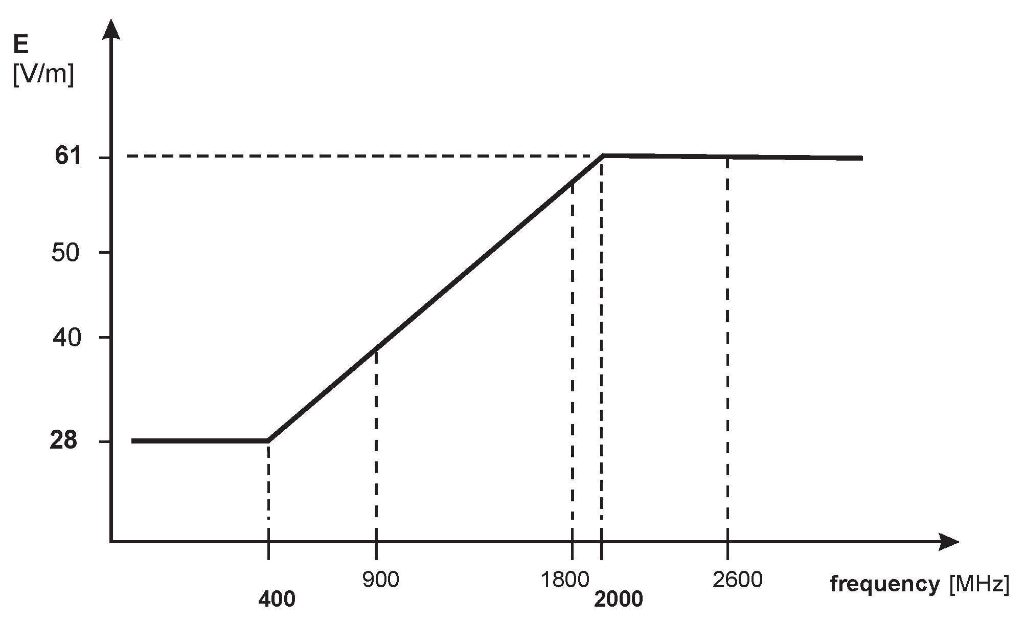
Established guidelines constitute that EM fields emitted by mobile base stations can reach levels up to 28 V/m in frequencies below 400 MHz and 61 V/m in frequencies above 2000 MHz. In the frequency range from 400 to 2000 MHz the permissive exposure level has a functional relationship depending on frequency with the value between 28 and 61 V/m [25]. Such reference levels as permissive exposure threshold was presented in Figure 3.
The permissive exposure levels, as is presented in Figure 3, must be maintained in the places in whereabouts of people, however, considering that the electric field strength decreases with the distance, in the vicinity of base station antenna the radiation can be even higher than 61 V/m. Therefore, the exposure level in the area close to base station is far higher than the mandatory EMC regulation, hence manufacturers cannot vouch for their devices’ efficacy under such intense radiation.
In consideration of above-conditioning, it is necessary to determine the practical distance from base station antennas where the value of electric field strength is higher than 30 V/m. The distance was determined based on the following relationship of electric field strength:
where:
- k – constant, k = 7,
- R – distance from the antenna [m],
- P – power (ERP) [W],
- E – electric field strength [V/m].
Therefore, the distance R can be expressed as:
In calculation, the value of effective radiated power P(ERP) of 40 dBW per sector has been accepted, as the maximum value, according to the EU Regulations [18]. The distance for such power has been calculated using relationship (3). Considering P[ERP] = 40 dBW and electric field threshold of E = 30 V/m, the safe distance is R = 20 m form the antenna. Obtained distance relates to the main beam of antenna radiation. In directions of antenna side lobes, the electric field can be lower according to the antenna pattern. However, along the main direction of antenna radiation, from the antenna till R = 20 m the value of electric field strength can be higher than threshold for safe drone flight and negative impacts must be taken into account. One ought to notice that the value of ERP = 40 dBW, taken for calculation, is rather maximal power feeding sectorial antennas and for base stations with lower power the separation distance (R) can be proportionately smaller.
6. Conclusions
The investigation on unmanned aerial vehicles safe flight in electromagnetic environment has been presented. The correct work of electronic devices can be provided when electromagnetic compatibility conditioning is fulfilled. The immunity threshold of electric field strength according to existing EMC standard for typical commercial drones was established as 10 V/m. However, guidelines for people protection allow us to reach the level of electric field strength up to 61 V/m. To recognize the drone vulnerability level, the investigation was carried out in an anechoic chamber. It was found that when electric field strength is 30 V/m or higher the generally available drones have unchecked fall. Considering the maximum possible base station antenna effective radiated power of 40 dBW per sector and electric field level of E = 30 V/m, the safe distance of R = 20 m from the antenna was determined.
The safe distance for UAVs around base station antennas, as a strong recommendation, should be respected by popular drone users.
Author Contributions
Conceptualisation, R.K., R.P. and D.L.; methodology, R.K. and D.L.; software, R.P.; validation, M.B., D.L.; formal analysis, R.K. and R.P.; writing—original draft preparation, R.K. M.B.; writing—review and editing, R.P., M.B. and D.L. All authors have read and agreed to the published version of the manuscript.
Funding
This research was funded by the National Centre for Research and Development, within project No. DOB-02/B/031/04/2021.
Data Availability Statement
The data are available in the manuscript in the form of results.
Conflicts of Interest
The authors declare no conflict of interest.
References
- Directive 2014/30/EU of the European Parliament and of the Council of 26 February 2014 on the harmonization of the laws of the Member States relating to electromagnetic compatibility, Official Journal of the European Union, L 96. 2014, 79–106.
- IEC 61000-4-3. Electromagnetic compatibility (EMC) – Part 4-3: Testing and measurement techniques – Radiated, radio-frequency, electromagnetic field immunity test, International Electrotechnical Commission, Edition 4.1. Geneva. 2020.
- Commission Delegated Regulation (EU) 2019/945 of 12 March 2019 on unmanned aircraft systems and on third-country operators of unmanned aircraft systems, Official Journal of the European Union, L 152. 2019, 1–40.
- Kang, H.; Joung,; Kim, J.; Kang, J.; Soo Cho, Y. Protect your sky: a survey of counter Unmanned Aerial Vehicle systems. IEEE Access 2020, 8, 168671–168710. [CrossRef]
- Zhao, M.; Chen, Y.; Zhou, X.; Zhang, D.; Nie, Y. Investigation on Falling and Damage Mechanisms of UAV Illuminated by HPM Pulses. IEEE Transactions on Electromagnetic Compatibility 2022, 64. [Google Scholar] [CrossRef]
- Backstrom, M.G.; Lovstrand, K.G. Susceptibility of electronic systems to high-power microwaves: Summary of test experience. IEEE Trans. Electromagn. Compat. 2004, 46, 396–403. [Google Scholar] [CrossRef]
- Birk, A.; Wiggerich, B.; Bulow, H.; Pfingsthorn, M.; Schwertfeger, S. Safety, security, and rescue missions with an unmanned aerial vehicle. J. Intell. Robot. Syst. 2011, 64. [Google Scholar] [CrossRef]
- Qiao, Z.; Pan, X.; He, Y.; Chen, H.; Shen, J.; Ye, C. Damage of high power electromagnetic pulse to unmanned aerial vehicles. High Power Laser Part. Beams 2017, 29. [Google Scholar]
- Zhang, D.; Zhou, X.; Cheng, E.; Wan, H.; Chen, Y. Investigation on Effects of HPM Pulse on UAV’s Datalink, IEEE Trans. Electromagnetic Compatibility 2020, 62. [Google Scholar]
- Zhang, J.; He, Y.; Pan, X.; Qiao, Z.; Chen, H.; Shen, J.; Yang, Z. Vulnerability analysis of UAV against mesoband electromagnetic pulse. Projectiles, Rockets Missiles Guid 2020, 40, 110–115. [Google Scholar]
- Zhang, Q.; Cheng, E.; Wang, Y.; Chen, Y.; Ma, L. Research on the electromagnetic interference effect of UAV satellite navigation system. J. Syst. Eng. Electron. 2020, 42, 2684–2691. [Google Scholar]
- Gao, C.; Xue, Z.; Ren, W. The influence of electromagnetic interference of HPM on UAV. International Conference on Microwave and Millimeter Wave Technology 2021, Nanjing, China, 23–26.
- Jia, Y.; Tu, X.; Yan, W.; Wang, E.; Zhao, Y.; Ding, S. Study on the Influence of Electromagnetic Pulse on UAV Communication Link. Am. J. Electr. Electron Eng. 2019, 7, 42–48. [Google Scholar] [CrossRef]
- Sakharov, K.; Sukhov, A.V.; Ugolev, V.L.; Gurevich, Y.M. Study of UWB Electromagnetic Pulse Impact on Commercial Unmanned Aerial Vehicle. International Symposium on Electromagnetic Compatibility (EMC EUROPE), Amsterdam, Netherlands, 2018, 27–30.
- Fan, L.; Pan, X.; Huang, Z.; Zu, X. The mechanism and experimental study on the interference of high voltage lines to navigation system. Lat. Am. Appl. Res. 2018, 48, 175–179. [Google Scholar] [CrossRef]
- He, K.; Yu, D.; Guo, B.; Chai, M.; Zhou, C.; Zhang, D. An Equivalent Dynamic Test System for Immunity Characterization of the UAV Positioning Module Using Bulk Current Injection Method. IEEE Letters Electromagn. Compat. 2020, 2, 161–714. [Google Scholar] [CrossRef]
- Zhao, M.; Wu, W.; Li, J.; Cheng, Y.; Ma, L.; Guo, J.; Liu, Y. Effect of High Altitude Electromagnetic Pulse on Flight Control System of Typical UAV. Mod. Appl. Phys. 2018, 18, 73–76. [Google Scholar]
- Commission Implementing Regulation (EU) 2019/947 on the rules and procedures for the operation of unmanned aircraft, Official Journal of the European Union, L 152. 2019, 45–71.
- Council Recommendation 1999/519/EC of 12 July 1999 on the limitation of exposure of the general public to electromagnetic fields (0 Hz to 300 GHz), Official Journal of the European Communities, L 199. 1999, 59–70.
- Mil-Std-461G, Requirements for the control of electromagnetic interference characteristics of subsystems and equipment, U.S. Department of Defense, Washington D.C. 2015, 11.
- EN 301-489-17, Electromagnetic Compatibility (EMC) standard for radio equipment and services – Part 17, Specific conditions for Broadband Data Transmission Systems. European Telecommunications Standards Institute, Sophia. 2022.
- EN 55032, Electromagnetic compatibility of multimedia equipment – Emission requirements, European Committee for Electrotechnical Standardization, Brussels. 2015.
- EN 61000-6-2, Electromagnetic compatibility (EMC) – Part 6-2: Generic standards – Immunity for industrial environments, European Committee for Electrotechnical Standardization, Brussels. 2016.
- IEC 61000-4-6, Electromagnetic compatibility (EMC) – Part 4-6: Testing and measurement techniques – Immunity to conducted disturbances, induced by radio-frequency fields, International Electrotechnical Commission, Edition 4.0, Geneva. 2014.
- IEEE Standard, for safety levels with respect to human exposure to electric, magnetic, and electromagnetic fields; 0 Hz to 300 GHz, IEEE Std C 95.1, New York USA. 2019.
Figure 1.
View of drone cables

Figure 2.
The drone fasten on the table in an anechoic chamber

Figure 3.
Reference levels of electric field strength for public exposure
Disclaimer/Publisher’s Note: The statements, opinions and data contained in all publications are solely those of the individual author(s) and contributor(s) and not of MDPI and/or the editor(s). MDPI and/or the editor(s) disclaim responsibility for any injury to people or property resulting from any ideas, methods, instructions or products referred to in the content. |
© 2025 by the authors. Licensee MDPI, Basel, Switzerland. This article is an open access article distributed under the terms and conditions of the Creative Commons Attribution (CC BY) license (http://creativecommons.org/licenses/by/4.0/).
Copyright: This open access article is published under a Creative Commons CC BY 4.0 license, which permit the free download, distribution, and reuse, provided that the author and preprint are cited in any reuse.


