Submitted:
11 September 2025
Posted:
12 September 2025
You are already at the latest version
Abstract
This paper proposes a hybrid strategy that integrates a Genetic Algorithm (GA) with Digital Twin (DT) technology to address the issue of nighttime reactive power backfeed in large-scale photovoltaic (PV) power plants. First, a GA is employed to optimize the location and number of multitask inverters to minimize line losses and eliminate the reactive power backfeed. Subsequently, the DT continuously monitors the grid conditions and performs a rolling dispatch of the inverter units to respond to the residual reactive power caused by the nighttime voltage fluctuations. The experimental results show that GA-based optimization reduces the line losses from 0.346 kW to 0.2818 kW, a reduction of approximately 18.6%, and helps to prevent thermal damage to the inverters. When combined with DT technology, the strategy further enhances voltage stability and demonstrates strong adaptive control capabilities. The proposed method effectively reduces the operation and maintenance costs of PV plants and shows a promising potential for practical deployment.
Keywords:
photovoltaic power plant
; nighttime reactive power compensation
; Genetic Algorithm
; Digital Twin
; real-time adjustment of reactive power reverse flow
1. Introduction
In many cases, large-scale photovoltaic (PV) power plants are installed far from load centers, and the power transmission lines are typically 161 kV underground cables with lengths ranging from several kilometers to several tens of kilometers. At night, when the PV systems do not generate electricity, they may inject reactive power back into the grid, leading to voltage instability at the interconnection point. When the reactive power in the regional grid is insufficient, the voltage tends to decrease. Conversely, excess reactive power can increase system voltage. To ensure voltage stability in such areas, utility companies often require PV plant operators to refrain from supplying reactive power to a grid.
Various voltage regulation strategies for (PV) have been studied, including constant power control, voltage regulation using energy storage systems (ESS), and the installation of reactive power compensation devices. Reference [1] proposed using an ESS to suppress voltage fluctuations in the grid; however, this approach requires additional ESS installations, thereby increasing the capital investment. In [2], both static and dynamic reactive power compensation devices were employed to enhance voltage stability in PV power plants; however, large-scale deployment entails higher investment costs. As analyzed in [3], when the PV penetration level exceeds 30%, the voltage regulation capability of inverters can effectively replace static reactive power compensation devices.
Inverter-based systems inherently generate reactive power during active power production and fulfilling the utility requirements for reactive power support during power generation is generally not an issue. However, when reactive power compensation is required during non-generating periods, the economic dispatch of inverters within PV plants to maintain voltage stability is a critical challenge, particularly under cost constraints. In recent years, several studies have proposed the concept of using photovoltaic systems as STATCOMs, referred to as PV-STATCOMs, with the primary objective of enhancing voltage stability [4,5].
Significant progress has been made in the study of nighttime reactive power compensation in photovoltaic (PV) systems. In a 2022 study by Lavi et al., the feasibility of using PV inverters to provide reactive power at night was explored to reduce grid operational costs. These results demonstrate the potential for economic and technical advantages [6]. Additionally, Rezende et al. (2022) proposed a reactive power optimization strategy for power systems involving PV plants using a GA. Their approach effectively improved the voltage profiles and ensured compliance with standard requirements [7]. However, these studies primarily focused on theoretical analysis and simulation validation, and lacked field-test data from large-scale PV plants. Further research is needed to verify the practical effectiveness and reliability of these methods. As noted in [8], the IEEE 1547-2018 standard requires distributed energy resources (DERs) to support voltage regulation, including the implementation of volt–var control. In this multitasking mode, inverters must adjust their reactive power output in response to voltage variations, which may increase the thermal stress on devices and ultimately affect their lifespan.
To address the issue of voltage instability potentially caused by a reactive power backfeed, this study employs a GA to optimize the placement and quantity of inverters. In addition to minimizing line losses, the proposed approach considers inverter thermal stress and aging risks. The design aims to enhance the operational efficiency of the inverter and extend the equipment lifespan.
GA is an efficient technique for rapidly obtaining near-optimal solutions and is particularly suitable for identifying the optimal placement and number of multitask inverters in large-scale PV power plants. Following GA-based optimization, a DT framework was employed to perform hourly rolling updates, dynamically adjusting the number of active inverters to mitigate the residual reactive power caused by nighttime voltage fluctuations. To validate the effectiveness of the proposed approach, DT-based simulations were conducted on a 120 MW large-scale photovoltaic power plant.
2. Genetic Algorithm
GA is a stochastic search algorithm inspired by the natural evolutionary processes observed in biological systems. It mimics mechanisms, such as selection, crossover, and mutation, which drive species evolution in nature. In each generation, the algorithm retains individuals with higher fitness and applies genetic operators to generate a new population that gradually approaches the global optimum. Because the GA does not rely on gradient information and exhibits strong global search capabilities, it is particularly suitable for solving optimization problems that are nonlinear, multiobjective, or involve discrete variables. The fundamental steps of GA are outlined as follows.
- Initialization: A set of candidate solutions, known as the initial population, is randomly generated. In this study, the population size was set at 1000;
- Fitness Evaluation: Each candidate solution is evaluated based on the objective function and constraint conditions to determine its fitness value.
- Selection: Based on the fitness values, a subset of high-performance candidate solutions is selected to serve as parents for the next generation.
- Crossover: Selected parent solutions are combined to produce new candidate solutions. In this study, 90% of new individuals in each generation were generated through crossover operations, whereas the remaining 10% were generated through mutations.
- Mutation: Candidate solutions are randomly modified to increase the population diversity and prevent premature convergence.
- Population Update: The current population is replaced with newly generated candidate solutions, and the process is repeated for multiple generations. In this study, the elitism size was set to 50, meaning that the top 50 individuals with the highest fitness were directly carried over to the next generation, without undergoing crossover or mutation. This mechanism ensures that the best solutions obtained thus far are not lost in the subsequent generations.
- Termination condition: The GA stops when a predefined termination condition is satisfied, such as reaching the maximum number of generations or finding a solution that satisfies the desired performance criteria.
In this study, the population size is set to 1000, and the crossover/mutation rates are configured as 0.9/0.1, respectively. These values were determined based on preliminary experiments that aimed to strike a balance between convergence speed and solution diversity. Additionally, a limited sensitivity analysis was conducted. The results indicate that when the population size falls below 500, inverter placement outcomes tend to be suboptimal. Moreover, increasing the mutation rate beyond 0.2 led to unstable convergence behavior during the evolutionary process. The complete execution procedure of the GA, including initialization, fitness evaluation, selection, crossover, mutation, population update, and termination, is summarized in Figure 1, which illustrates the overall workflow of GA-based optimization.
The primary objective of this study is to determine the number of inverters to be dispatched and to identify which regions’ inverters should participate in reactive power absorption by solving an optimization problem. The objective function is defined as follows:.
Constraints are defined as
where
Reactive power supplied by underground cables.
Reactive power absorbed by underground cables and distribution transformers during nighttime operation.
Total reactive power absorbed by inverters during nighttime operation.
The line losses resulting from the participation of multi-task inverters.
Number of inverters participating in reactive power compensation.
, are the weights
( in this study).
is the amount of reactive power compensated for by inverter i.
In this study, the Constraint Tolerance for the GA optimization process was set to constraint Tolerance = 1e-5, which represents a strict constraint setting. This ensures that all candidate solutions closely satisfy the equality condition of total reactive power absorption. Under these conditions, the minimized objective value obtained can be considered highly reliable.
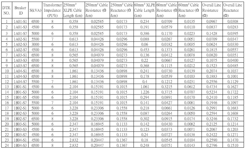
Figure 2 shows a single-line diagram of the actual photovoltaic (PV) power plant used in the GA implementation. The total installed capacity of the plant was approximately 120 MW, comprising 24 step-up substations and 1292 inverters, each rated at 100 kW. A scada system was installed across all critical nodes from the DC side to the AC side for real-time monitoring and data-logging. The specifications of the distribution transformers, conductor types, and impedance data within the plant are detailed in Table 1, which serves as the basis for the subsequent DT simulation and parameter modeling.
The PV plant under study was integrated into a power system in October 2024. However, at night, it injects approximately 2.8 MVAr of reactive power into a grid. The symbol “—“ indicates power flowing into the grid. The daily active power generation and night-time reactive power backfeed are shown in Figure 3.
In the figure, the symbol indicates the direction of power flow into the grid. To address the issue of nighttime reactive power backfeed, the proposed GA-based method was applied to identify the optimal locations and select 55 inverters to operate in multitask mode. Under normal system voltage conditions (1.0 pu), the reactive power backfeed was effectively reduced from 2.8 MVAr to 0.00217 MVAr, with an associated line loss of approximately 0.386 kW. Figure 4 and Figure 5 illustrate the improvements achieved by using the proposed strategy.
This study extends the GA framework established in [9], incorporating its optimization structure and objective formulation as the basis for the proposed DT-based real-time dispatch mechanism.
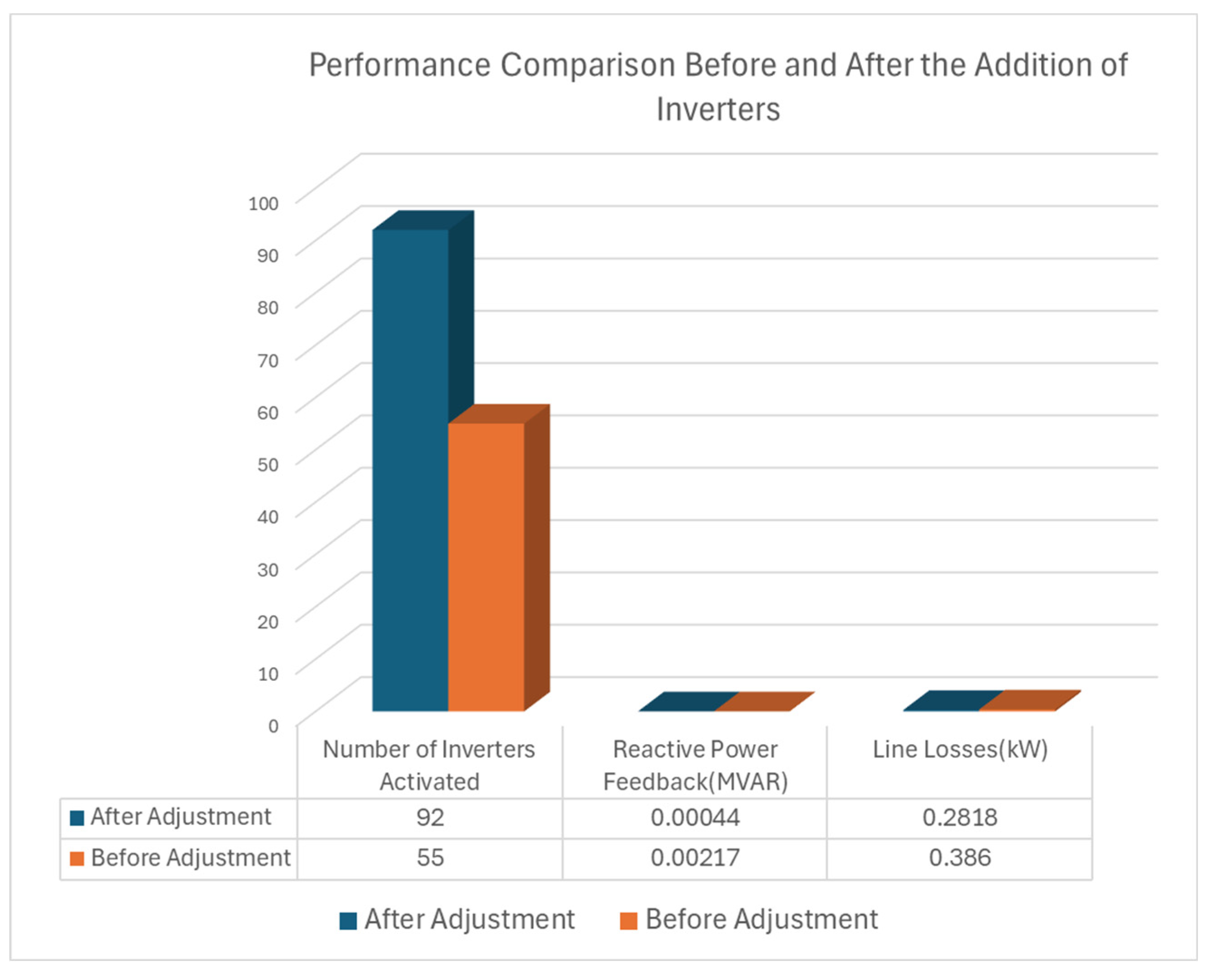
However, during night-time reactive power absorption, several multitask inverters exhibit signs of thermal stress, with internal temperatures reaching approximately 50 °C, resulting in degraded performance in some units. To mitigate this issue, the reactive power output per inverter was reduced from 50 to 30 kVAr and GA-based optimization was executed again to determine a new set of optimal locations and inverter quantities. Consequently, the number of active inverters increases from 55 to 92, effectively resolving the thermal degradation problem. Furthermore, the line losses were reduced from 0.386 kW to 0.2818 kW, representing an 18.6% reduction. Figure 6 and Figure 8 show the system performance after this adjustment.
Figure 5.
Reactive power flow at PCC after GA optimization, demonstrating suppression to 0.00217 MVAr. (Data source: Taipower SCADA.).
Figure 5.
Reactive power flow at PCC after GA optimization, demonstrating suppression to 0.00217 MVAr. (Data source: Taipower SCADA.).
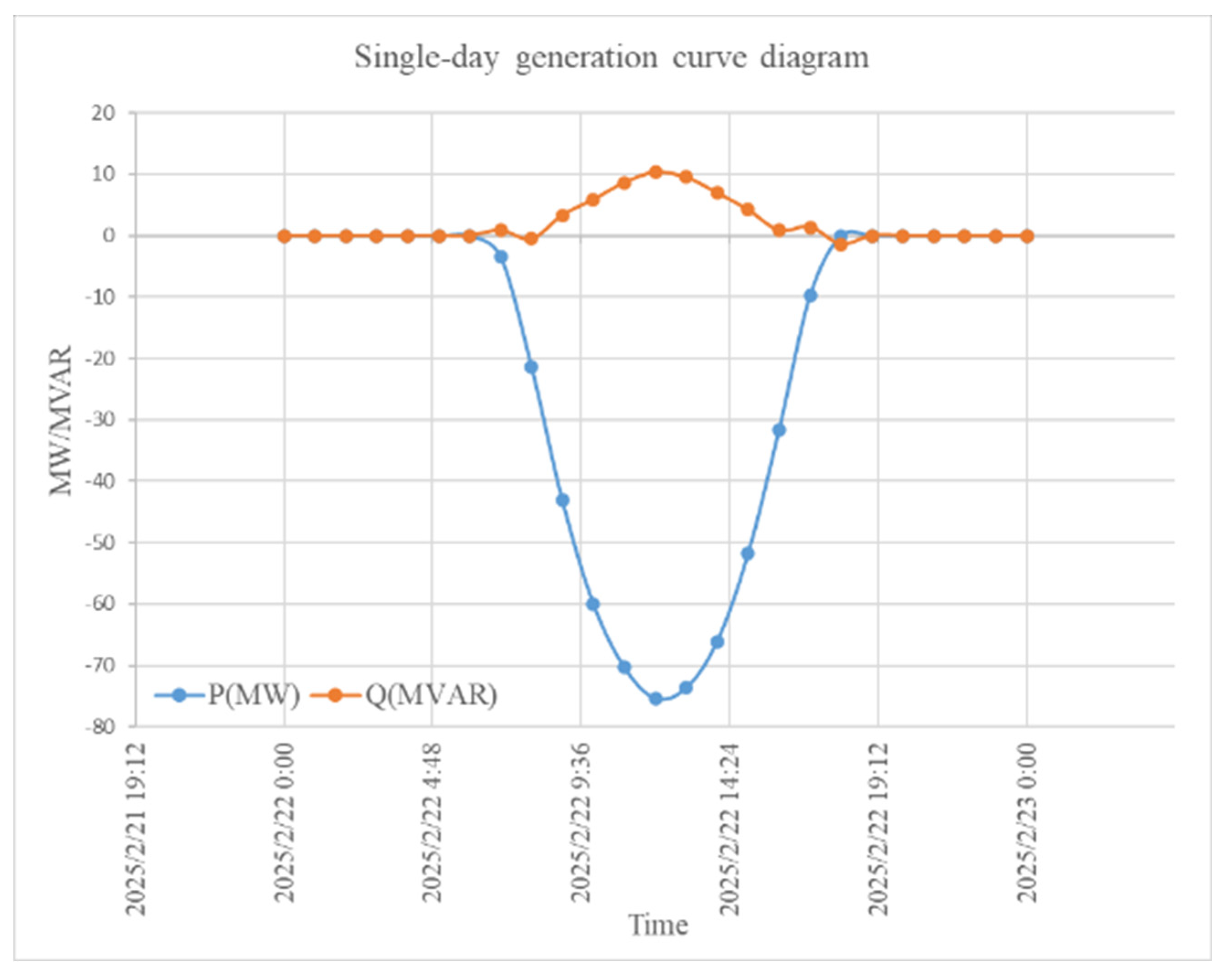
Figure 6.
Updated Placement and Quantity of Inverters.

Figure 7.
Convergence Curve of the Objective Function After Adjustment.
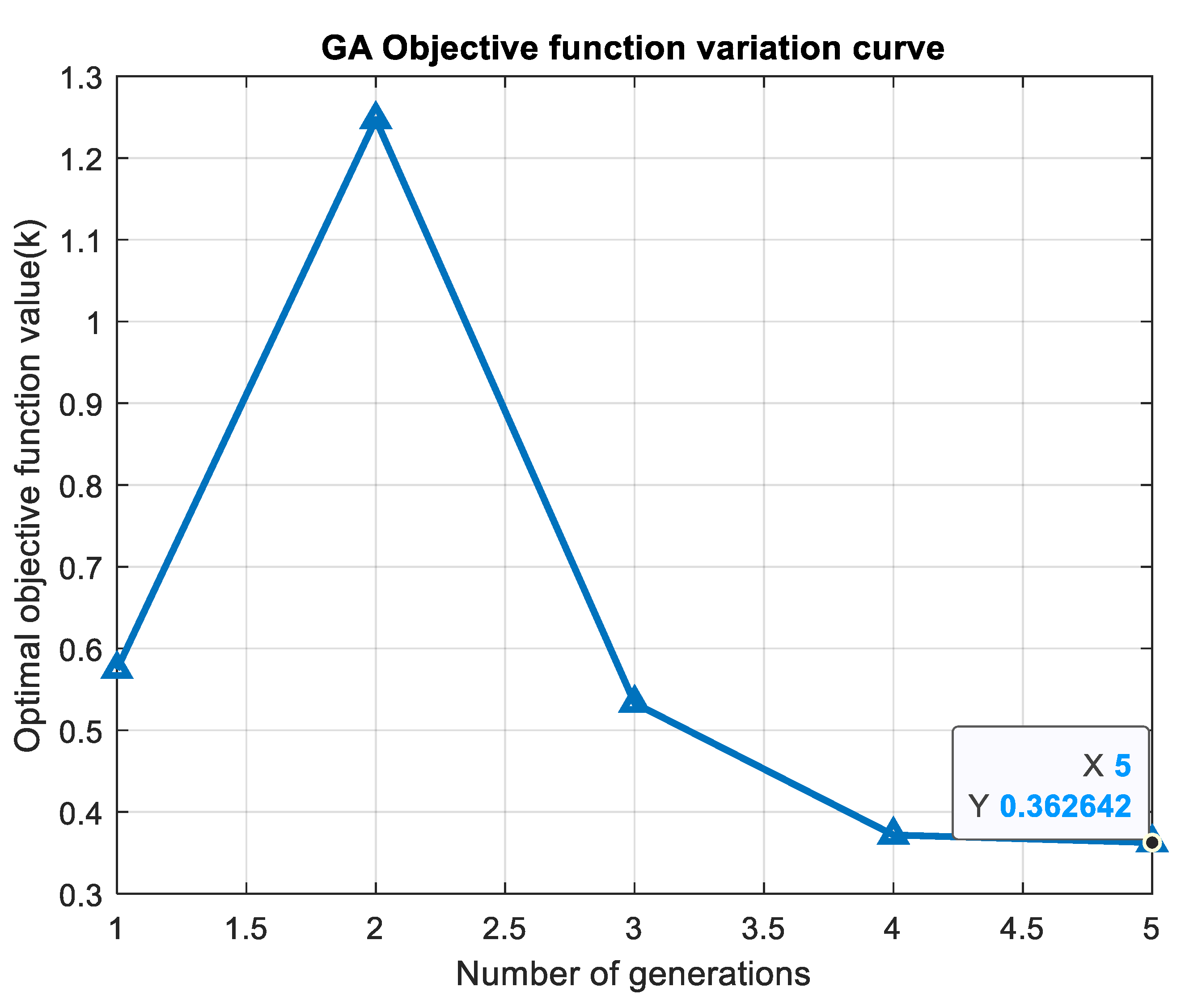
Figure 8.
Performance Comparison of Inverters Before and After Adjustment.
3. Digital Twin (DT)
The concept of DT was initially introduced in the manufacturing domain with the aim of enhancing system operation and decision making through cyber-physical integration and improved monitoring. DT enables the integration of multiple simulation and analysis tools supported by continuous data exchange and feedback mechanisms to achieve dynamic system adjustments and predictive capabilities [10]. DT is considered to be a relatively new technology in power systems. With accurate modeling, a self-adaptive virtual replica of the physical system can be constructed to support the monitoring, testing, and control tasks. A key distinction between DT models and conventional mathematical models lies in the DT’s ability to autonomously adjust its parameters in real time, thereby reflecting the actual system behavior more effectively [11].
Considering that the nighttime voltage in power systems may fluctuate because of varying load conditions, residual reactive power may arise in the PV plant. A one-time static optimization of the inverter deployment cannot effectively respond to such voltage variations, which may lead to reverse reactive power issues such as over-absorption or backfeeding. Therefore, it is necessary to introduce a self-adaptive Digital Twin (DT) model to enable the rolling control. In this context, the present study incorporates DT technology to achieve real-time inverter dispatch to mitigate reactive power backfeed through dynamic hour-by-hour adjustments.
The Digital Twin framework includes the following simulation modules:
- Reactive power demand variation (based on real-time data);
- Point of Common Coupling,(PCC) voltage estimation (considering reactive power–voltage sensitivity)
- Residual reactive power calculation and assessmen.
The Digital Twin (DT) dynamically evaluates the system status on an hourly basis by reassessing the reactive power backfeed and the deviations in the PCC voltage. Based on the updated system conditions, DT adjusts the activation states of the inverters according to the following decision logic:
- If the voltage exceeds the specified threshold or the residual reactive power is positive (indicating a reverse flow to the grid), the number of active inverters is appropriately increased.
- If the voltage falls below the specified threshold or the residual reactive power is negative (indicating overabsorption), a portion of the inverter is deactivated selectively.
The relationship between the reactive power variation and number of inverters is described as follows:
where
Reactive power variation in the underground transmission cable caused by PCC voltage fluctuations.
Reactive power generated by the cable during nighttime.
Total reactive power in the reverse-fed system.
Reactive power absorbed by each inverter.
Inverter Count for Reactive Power Backfeed Mitigation.
The details of the DT-based inverter dispatch strategy in response to system voltage variations are illustrated in Figure 9.
In this study, the SCADA architecture within a PV power plant was regarded as the data source for the DT system. It provides hourly measurements of critical parameters such as the PCC voltage, residual reactive power, and inverter activation status. These real-time data are fed into the DT model, enabling dynamic updates of the reactive power demand and system parameters, such as voltage and reactive power sensitivity, based on voltage fluctuations. Although the DT mechanism is not physically deployed on-site, the use of data-driven simulation allows for a realistic emulation of the system behavior under various loading and voltage conditions. This approach effectively demonstrates the feasibility and potential of the DT model for rolling inverter dispatch and mitigation of the nighttime reactive power backfeed.
4. Simulation Study
This section presents simulations for two operating conditions: one where the system voltage falls below the nominal value of 1.0 pu, and another where the voltage exceeds this nominal level.
4.1. Scenario with Undervoltage Conditions
In this scenario, it is assumed that between 18:00 and 00:00, the increased load demand causes the system voltage to drop to 0.95 pu. The relationship between the reactive power in the underground cable and system voltage is expressed as follows:
Owing to the voltage drop, the underground transmission cable generated approximately 2.527 MVAr of reactive power, which is lower than that 2.8 MVAr observed at a nominal voltage of 1.0 pu. Upon the detection of the reduced residual reactive power and voltage deviation, the DT model promptly deactivates the eight inverters to avoid overcompensation. The left half of Figure 10 illustrates the undervoltage conditions that occur at the PCC between 18:00 and 00:00. Correspondingly, the left half of Figure 11 shows how the DT model deactivates the selected inverters during this period, to prevent excessive reactive power absorption.
The left half of Figure 12 shows that after real-time adjustment of the number of active inverters using the DT model, the residual reactive power was effectively reduced to 0.013 MVAr.
The simulation results conducted in MATLAB demonstrated that the DT exhibits strong self-adaptive capabilities. It can accurately detect variations in the residual reactive power caused by system voltage fluctuations and promptly execute inverter-dispatch decisions. This highlights the high sensitivity and adaptability of the DT model, which enables the real-time correction of the reactive power distribution and voltage deviations during multitask inverter operation, thereby achieving closed-loop control objectives.
4.2. Scenario Under Overvoltage Conditions:
In this scenario, it is assumed that between 00:00 and 06:00, a decrease in the load demand causes the system voltage to rise to 1.05 pu. The right half of Figure 10 shows the overvoltage condition at the PCC during this period, which returned to normal daytime conditions after 06:00. The right half of Figure 11 indicates that the DT model detects an increase in the reactive power backfeed to 3.087 MVAr owing to the voltage rise. To prevent insufficient reactive power compensation, the DT dispatches 11 additional inverters in addition to the existing 92 inverters, resulting in a total of 103 activated inverters. After 06:00, the DT fully deactivates the multi-task inverter mode.The right half of Figure 12 shows that under the overvoltage condition, the DT successfully controls the reactive power backfeed to as low as 0.003 MVAr, demonstrating its capability for real-time reactive power regulation. Figure 13 illustrates the inverter dispatch curve governed by the DT model, which clearly shows the variation in the number of active inverters during the voltage fluctuation period between 18:00 and 06:00. After 06:00, the system exits the multitask inverter operation mode and returns to normal daytime generation, marking the end of the nighttime real-time reactive power compensation using the proposed hybrid GA–DT strategy for large-scale PV plants.
5. Conclusions
This study proposes a hybrid strategy that integrates a Genetic Algorithm (GA) with Digital Twin (DT) technology to address nighttime voltage fluctuations caused by reactive power backfeeds from underground cables in large-scale (PV) power plants. The proposed method reduces the residual reactive power, dynamically adjusts the inverter dispatch under overvoltage and undervoltage scenarios, and enhances overall voltage stability. By optimizing the reconfiguration of multi-task inverters through GA, the reactive power backfeed was reduced from 2.8 MVAr to 0.00217 MVAr. In addition, the inverter thermal stress was alleviated and the line losses were minimized to 0.2818 kW.
The introduction of Digital Twin (DT) technology during nighttime operation further enhances the adaptability of the system. Simulation results show that the DT can detect voltage deviations and residual reactive power fluctuations in real time. Under overvoltage conditions, the DT automatically activates 11 additional inverters to maintain reactive power balance and stabilize the residual reactive power within a minimal range. Conversely, under undervoltage conditions, it deactivates 8 inverters to prevent overcompensation, demonstrating high sensitivity and self-adaptive control capability. While Teng et al. [12] focus on SVG-based DT applications, the GA–DT hybrid strategy proposed in this study extends the concept to multitask inverter dispatch in large-scale PV power plants, with a particular emphasis on addressing nighttime overvoltage and undervoltage issues through effective reactive power management. Additionally, the GA–DT strategy proposed in this study, supported by full-hour simulations and SCADA-based field measurements, demonstrates strong adaptability and high feasibility, making it highly scalable for future intelligent PV power plants.
In contrast to the previous study [9], which focused solely on optimizing the reactive power equipment investment using a GA, the present study integrates a DT-based real-time dispatch mechanism to dynamically adjust the inverter operation under nighttime overvoltage scenarios. The proposed approach is further supported by full-hour simulations and field-measured data. Overall, the GA–DT hybrid strategy effectively reduces line losses and inverter thermal risks, while enabling real-time reactive power compensation and closed-loop voltage control in response to nighttime grid dynamics. This method exhibits strong practical scalability and deployment potential, contributing to reliable and cost-effective operation and maintenance of future intelligent PV power plants.
Future work may explore integrating integrating Long Short-Term Memory (LSTM)-based voltage forecasting models into the DT framework to proactively schedule inverter groups in anticipation of grid fluctuations.
Acknowledgments
The authors would like to thank Fimer S.p.A. for providing inverter technical documentation and Taiwan Power Company for supplying the SCADA data used in this study.
References
- W. Wang, W. He, J. Cheng, X. Huang, H. Liu. “Active and reactive power coordinated control strategy of battery energy storage system in active distribution network,” in Conf. Rec. 2017 IEEE Automation. pp. 462-465.
- H. Al-Mubarak, M. H. Khan, M. Z. Al-Kadhem. “Dynamic Reactive Power Compensation for voltage support using Static VAR Compensator (SVC) In Saudi Arabia,” in Conf. Rec. 2016 IEEE Electrical Power and Energy Conference. pp. 484-490.
- K. Turitsyn, P. Sulc, S. Backhaus, M. Chertkov. “Options for Control of Reactive Power by Distributed Photovoltaic Generators,” Proc. IEEE,vol.99, no. 6, pp. 1063-1073, Jun. 2011.
- E. Demirok, D. Sera, R. Teodorescu, P. Rodriguez and U. Borup, “Evaluaton of the voltage support strategies for the low voltage grid connected PV generators,” in Proc. Energy Convers. Congr. Expo., pp. 710-717, Sept. 2010.
- E. Demirok, P. G. Casado, K. H. B. Frederiksen, D. Sera, P. Rodriguez, and R. Teodorescu, “Local reactive power control methods for overvoltage prevention of distributed solar inverters in low-voltage grids,” IEEE J. Photovolt., vol.1, no.2, pp. 174-182, Oct. 2011.
- Yamit Lavi , Jay Apt “Using PV inverters for voltage support at night can lower grid costs,” 2352-4847/© 2022 The Author(s). Published by Elsevier Ltd. This is an open access article under the CC BY license (http://creativecommons.org/licenses/by/4.0/).
- J. O. REZENDE, G. C. GUIMARÃES, P. H.O. REZENDE “Control of Reactive Power with Genetic Algorithm in Electrical Power Systems with Photovoltaic Power Plant,” ENGINEERING SCIENCES • An. Acad. Bras. Ciênc. 94 (2) • 2022. [CrossRef]
- J. Flicker, J. Johnson, M. J. Reno, J. A. Azzolini, P. Hacke, and R. Thiagara-jan, “Inverter reliability estimation for advanced inverter functionality,” in Proc. IEEE 49th Photovolt. Specialists Conf., 2022, pp. 0183–0189.
- Liu, Y.-M.; Kuo, C.-C.; Chen, H.-C. Nighttime Reactive Power Optimization for Large-Scale PV Plants: Minimizing Compensation Equipment Investment. Preprints 2025, 2025090702. [CrossRef]
- W. Derigent, O. Cardin, and D. Trentesaux, “Industry 4.0: contributions of holonic manufacturing control architectures and future challenges,” J Intell Manuf, vol. 3, 3–4, p. 157, 2020.
- G. Bhatti, H. Mohan, and R. Raja Singh, “Towards the future of smart electric vehicles: Digital twin technology,” Renewable and Sustainable Energy Reviews, vol. 141, p. 110801, 2021.
- Teng, Y., Zhang, J., Wang, M., & Li, X. (2025). Digital twin system framework and application outlook. Electric Power Systems Research, 221, 110921. [CrossRef]
Figure 1.
Process of GA.
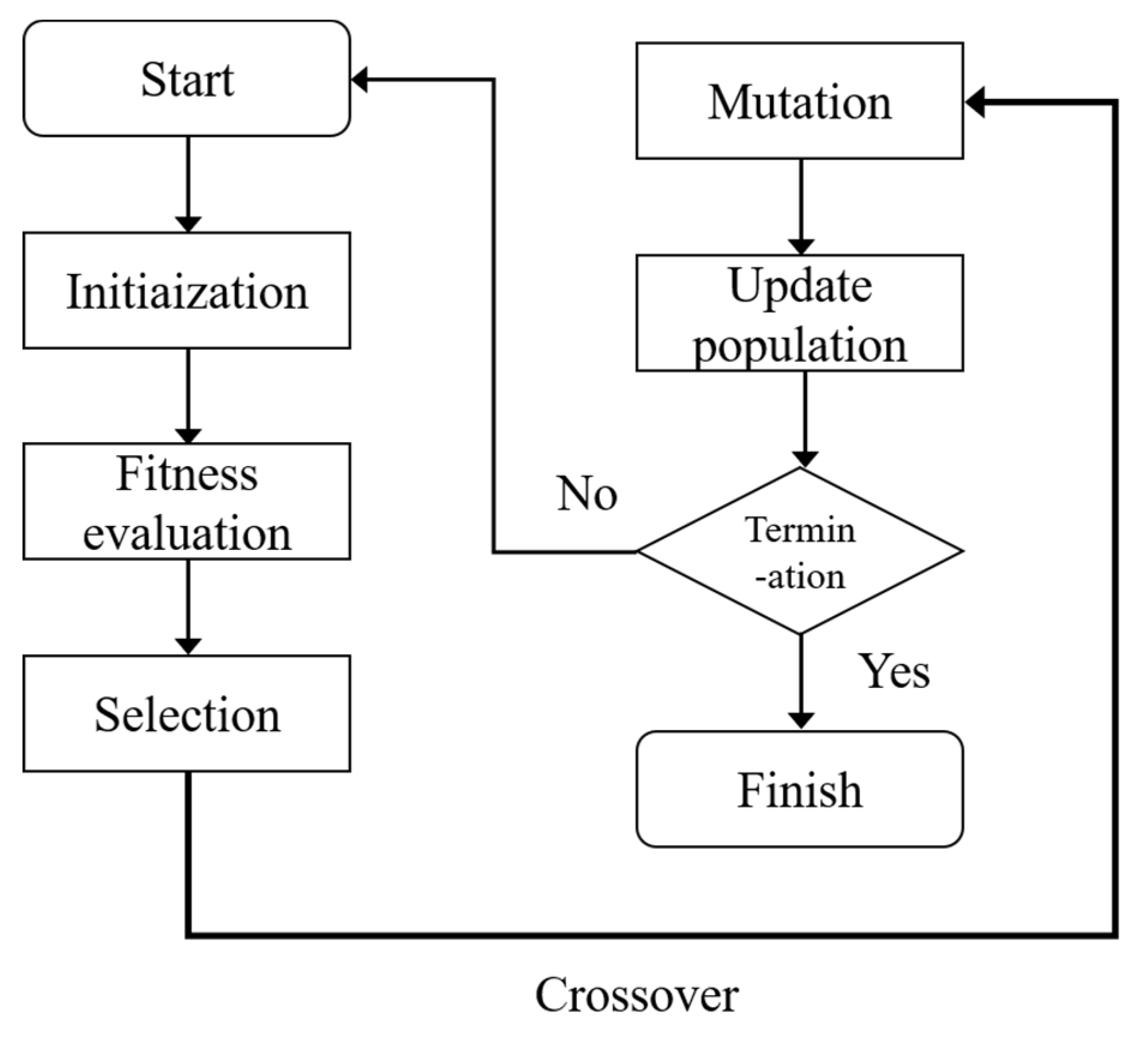
Figure 2.
Single-line diagram of PV plant.
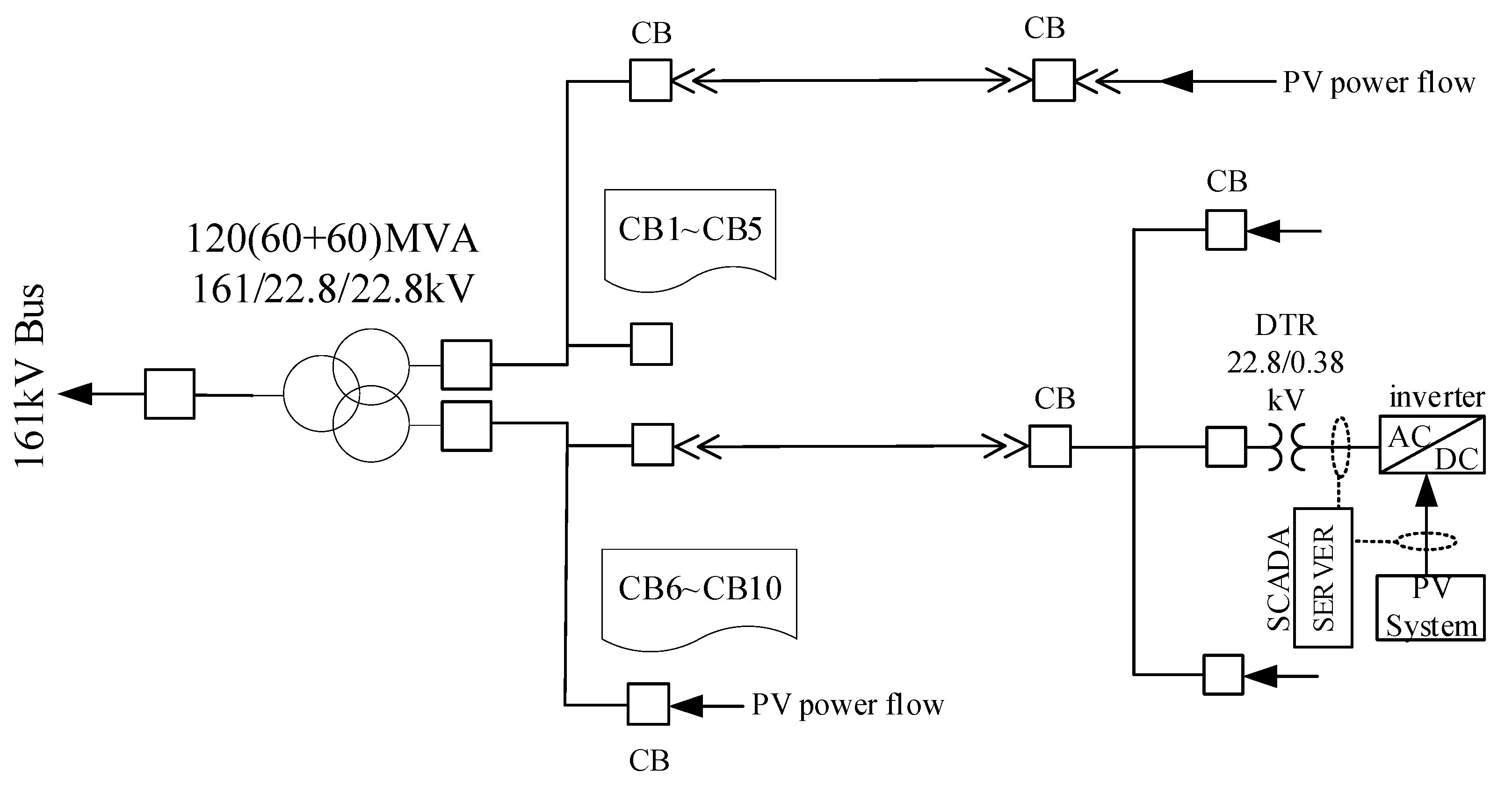
Figure 3.
Power flow curve of the solar power plant before improvement. (Data source: Taipower SCADA).
Figure 3.
Power flow curve of the solar power plant before improvement. (Data source: Taipower SCADA).
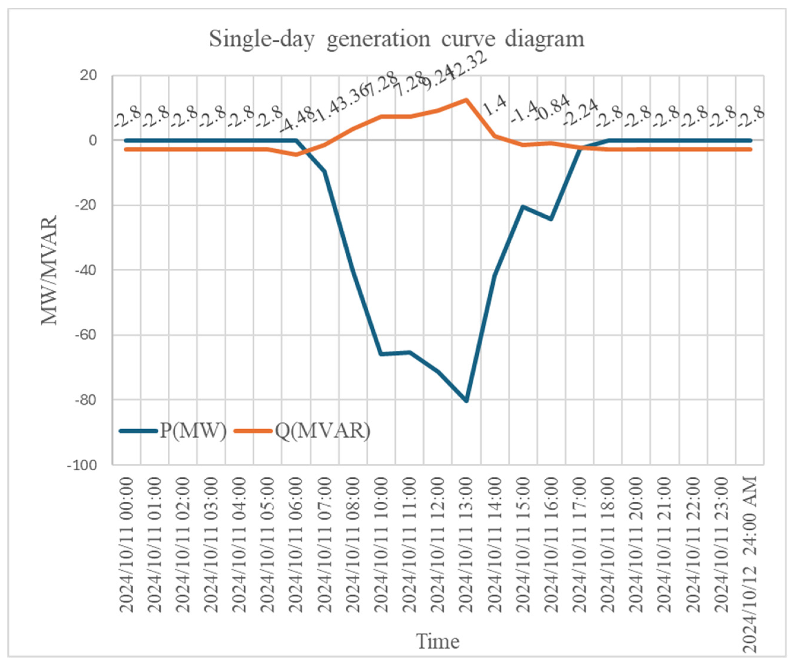
Figure 4.
Optimal inverter placement identified by GA. The solution selects DTR No.2, No.4, and No.5, which are closer to the PCC with lower line impedances, enabling effective reactive power support with fewer inverters.
Figure 4.
Optimal inverter placement identified by GA. The solution selects DTR No.2, No.4, and No.5, which are closer to the PCC with lower line impedances, enabling effective reactive power support with fewer inverters.
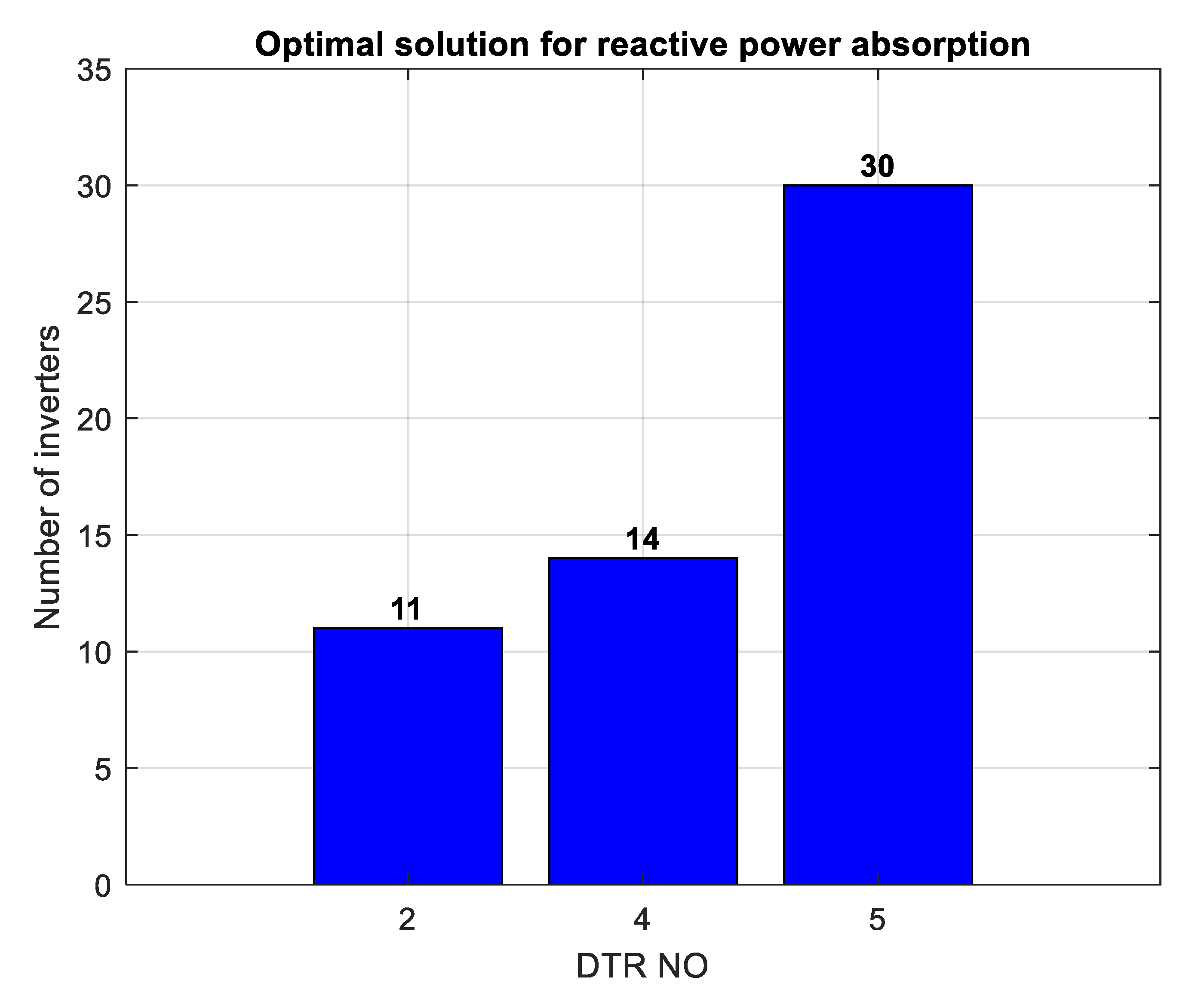
Figure 9.
Operational flowchart of the Digital Twin (DT) inverter dispatch strategy.
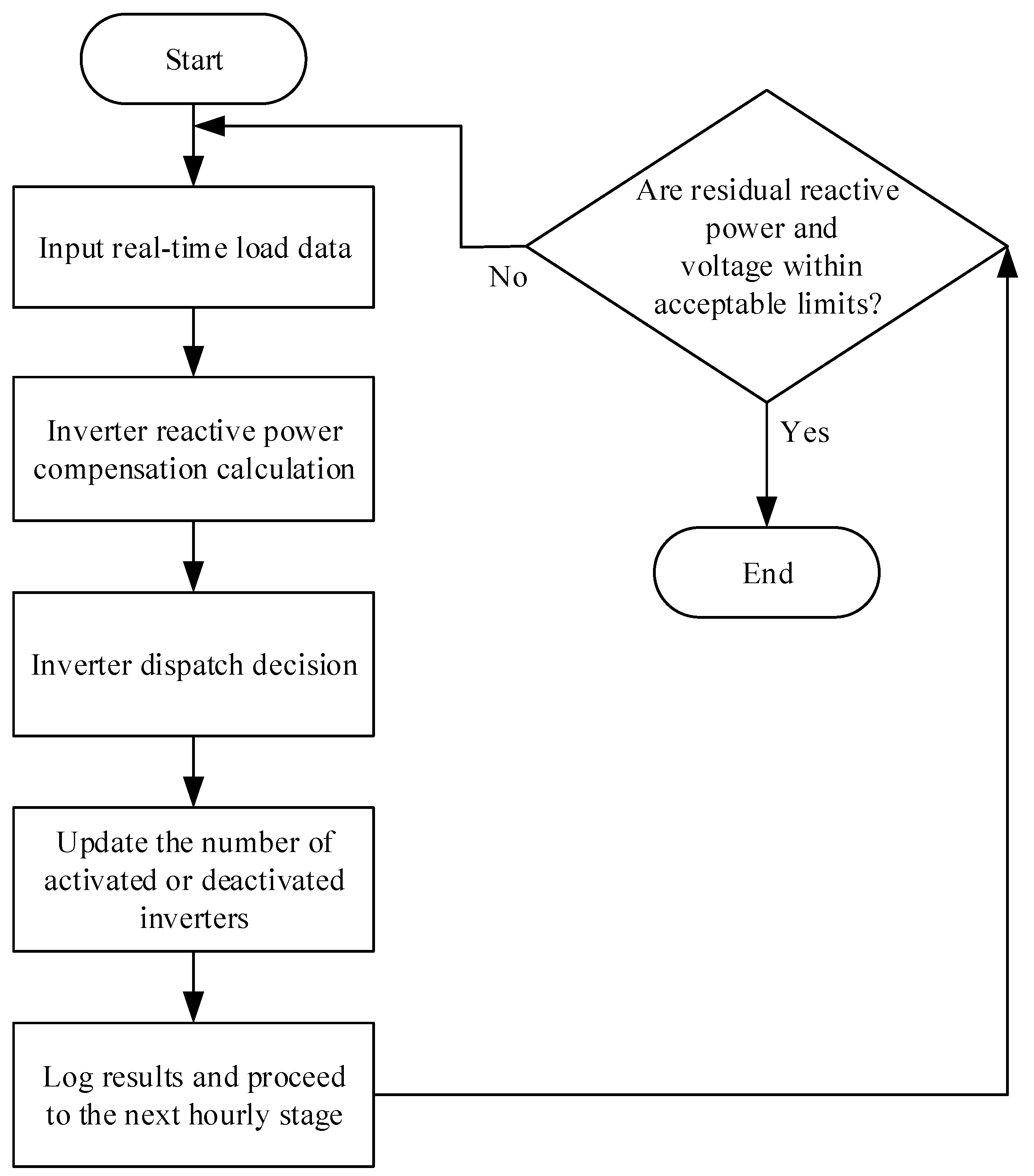
Figure 10.
Scenario Under Overvoltage Conditions.
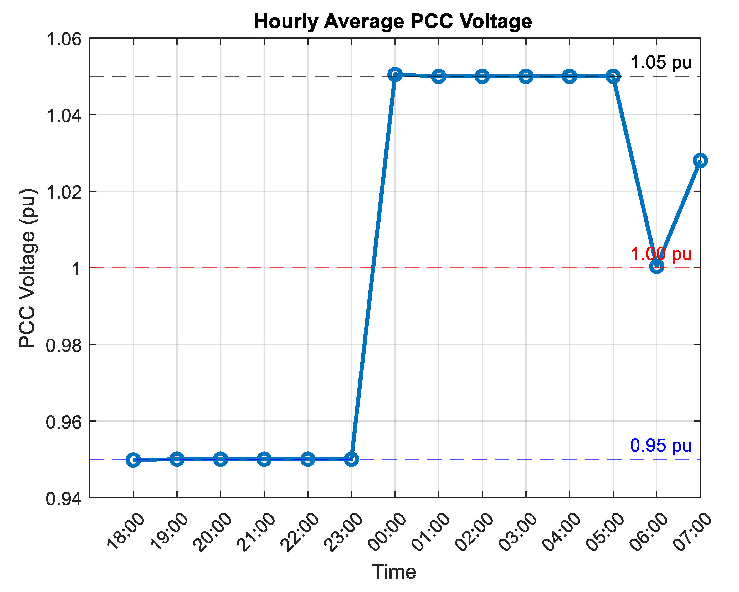
Figure 11.
Time Periods of Inverter Dispatch under DT Control.
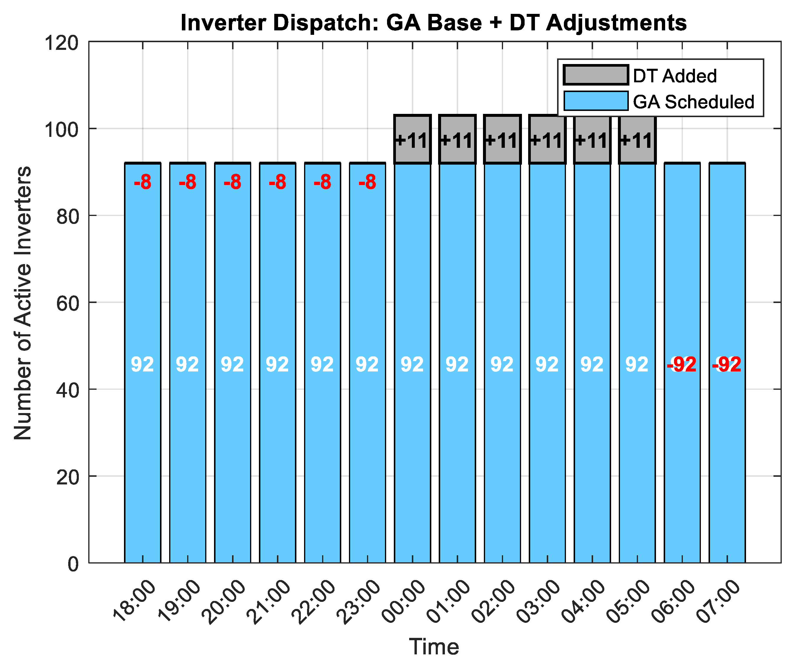
Figure 12.
Residual Reactive Power After DT-Based Improvement.
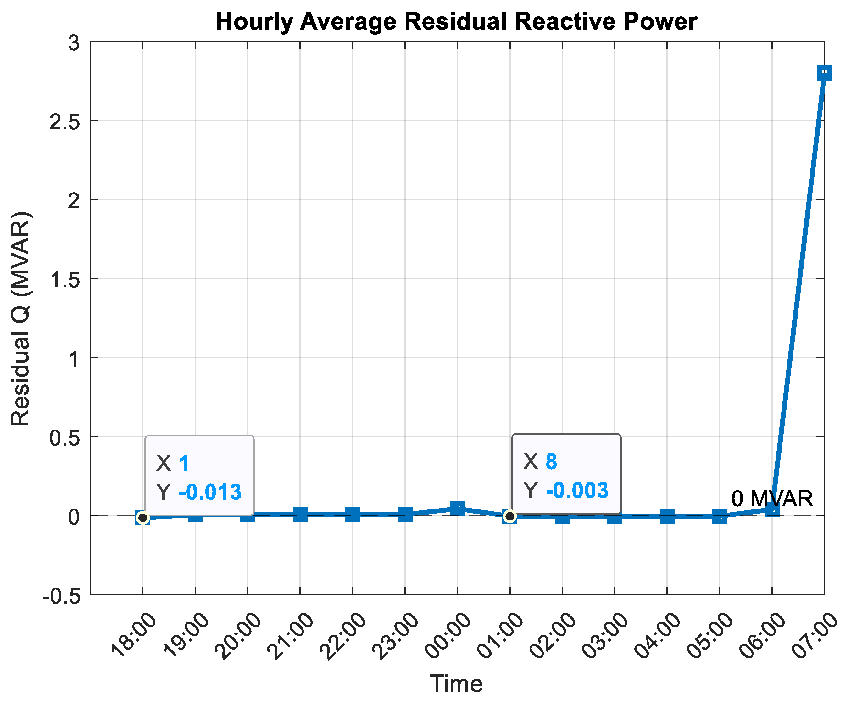
Figure 13.
Inverter Dispatch Curve Under DT-Based Multi-Task Operation.
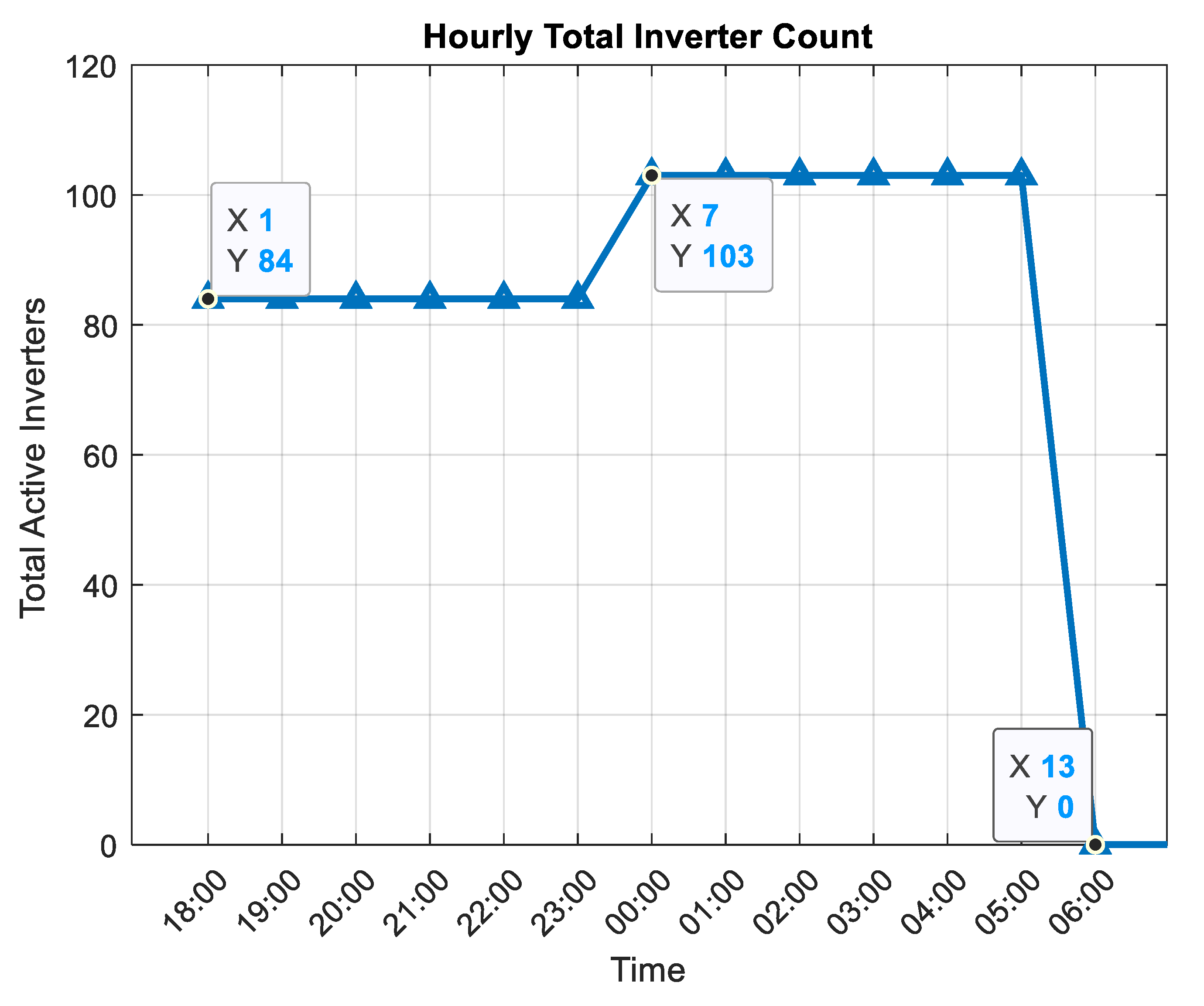

Table 1.
Impedance characteristics of transformers and cables.
 |
Disclaimer/Publisher’s Note: The statements, opinions and data contained in all publications are solely those of the individual author(s) and contributor(s) and not of MDPI and/or the editor(s). MDPI and/or the editor(s) disclaim responsibility for any injury to people or property resulting from any ideas, methods, instructions or products referred to in the content. |
© 2025 by the authors. Licensee MDPI, Basel, Switzerland. This article is an open access article distributed under the terms and conditions of the Creative Commons Attribution (CC BY) license (http://creativecommons.org/licenses/by/4.0/).
Copyright: This open access article is published under a Creative Commons CC BY 4.0 license, which permit the free download, distribution, and reuse, provided that the author and preprint are cited in any reuse.


