Submitted:
09 September 2025
Posted:
10 September 2025
You are already at the latest version
Abstract
The distribution of electricity is commonly done in 3 phase radial network or loop type system. The voltage varies from 34 KV (Kilovolts) down to 13.8 or 11 KV. The single-phase transformers are evenly distributed or connected along the system, that causes unbalance loading to the system as the load behavior of the customers is dynamically changing.
Due to these unbalance loading, the voltage at the sending end is adjusted by the distribution operator to compensate for the unbalance. The voltage regulator (VR) used has a maximum tap setting capacity that when the unbalance occurs and beyond the capability of the VR, the unbalance voltage will be imminent. Therefore, the operator has no option, although this can rarely happen, but to change the physical connection of a few single-phase transformers connected to the system to correct the unbalances. Power interruption is needed to execute the desired connection of the single-phase transformer, and the duration varies depending on the type of connector used. Hotline clamps are commonly used along overhead lines but sometimes wedge type or clamp connector is used. The process of removing and transferring the transformer leads and, in most cases, the primary leads are either long or short to the new phase and therefore is not efficient and the safety of personnel is always in question as this is done with the live line procedure when hot line clamp was utilized.
This research paper investigated the potential of a new hardware to be permanently connected to all the single-phase transformers that can facilitate the needed changing of phase connection should the unbalance in the system be beyond the VR tap setting limits and the on-load tap changer (OLTC) of the substation transformer. The aim of this new hardware design is to have a fast and efficient way to transfer the phase connection of single-phase transformers to any desired phase (AB, BC, or CA). The research is currently limited to the control unit using electromechanical relays and timers.
Keywords:
distribution
; transformer
; regulator
; unbalance
; interruption
; relay
; network
1. Introduction
The net zero plan of the government is also putting pressure to all Distribution Network Operator (DNO) as one of this is the phasing out of gas fired boiler and this only means that electricity driven heat pump will need to be utilised, and this is additional potential single-phase loads that could contribute to the three-phase unbalance system. The recent acquisition of Northern Irish heat pump manufacturer (Renewable Energy Devices) by Octopus Energy, Craigavon that will scale up the production of the latter to over 12,000 units per year. This is tied up with the government boiler upgrade scheme that soon attract more and more households switching to heat pumps (Energy Live News, 2022). The head of UKPN Smart Grid development Sotiris Georgiopoulos said ‘This is a critical time for all energy networks.
The single-phase transformers along the distribution line should be flexible on which phase it can be connected without lengthy interruptions. Currently these transformers are permanently connected to 11, 24, or 33 KV distribution line. With this initial study, on how to possibly overcome the switching procedure of changing the connection of the single transformers, the conventional electromechanical relay will be utilized to demonstrate the potential of this concept. Figure 1 is a diagram of the main relay contactor.
2. Literature Review
Three phase system current flows over three wires with a neutral (ideally zero current if balanced) if the system is distributed in a wye connected fashion. Single phase loads are connected by using one of the phase circuits and the neutral which is common practice in distribution sector. Other system design uses just three phase conductors without the neutral on high voltage distribution network and the neutral is just grounded on the main substation. Regardless of the design of the system the unbalanced circuit phenomenon is always given as there are combinations of three phase loads and single-phase loads on the network. Unbalanced loading reduced efficiency, dependability, and the safety aspect of the network due to the neutral current flowing on the network. The ideal system should have a vector sum of zero as this is separated by 120 degrees and equal magnitude (Y. Zerguit et al, 2023).
Several studies and research are trying to address this problem using different methodologies and the location of the equipment proposed. The recent paper from IEEE dated 27 July 2017 ‘An improvement of voltage unbalance in a low voltage 11/0.4 kV electric power distribution network under 3-phase unbalance load condition using dynamic voltage restorer’ (Mohammadpour et al., 2017), entails the solution to the problem by injecting the missing voltage to the system to have an optimal load voltage at the feeder 3 phase The Dynamic voltage restorer (DVR) is one way to compensate the unbalance voltage of the system by releasing the appropriate magnitude and direction of missing voltage to the network. DVR is composed of direct current (DC) source to Alternating Current (AC) switching inverter that is connected to the injection transformer which is in series to the system (O.P. Taiwo et al, 2017). Few obstacles that need to be incorporated with the DVR concept like the DC supply of the equipment, the fault current level of the equipment and the number of operation that the DVR needs to execute before the maintenance if this will be utilized in the main feeder of 11 or 33 KV level.
A present-day single line diagram of 3 phase-13.8KV distribution shown in Figure 1, shows the number of single-phase transformers connected into the system clearly outnumbered the 3-phase bank (DECORP (Dagupan Electric Company), 2023). The current connection of transformer is wedge type connection via sectionizing cutout fuse. Transferring the phase connection of a single-phase transformer to the desired phase with a wedge connection needs time and special tools (impact tools) to release the stirrup. If the hotline clamp was utilized, the primary leads could be short or long therefore new leads are needed.
A relay-based automatic balancing system for three phase loads could be a breakthrough into a more efficient and flexible way of balancing the network. The relay-based switching mechanism will achieve the optimum balance loading by closing and opening of several interlocked relays that is controlled by microcontroller (Y. Zerguit et al, 2023). The architecture applied on this technique is beneficial to adopt on main feeder of distribution line to dynamically transfer the single-phase transformers to optimum configuration of the feeder. Both DVR and relay based balancing mechanism can be used simultaneously as per their respective advantages. The DVR on the load side of the customer to mitigate fault current issue and relay-based system on the main feeder line.
3. Design
The design started by defining the requirements of the contactors and relays as shown in the table below.

Table 1.
Relay/Contactors requirements in the design.
| Relay / Contactors | NO (Normally Open) | NC (Normally Closed) |
| A (240 Volts coil) | 4 NC | |
| B (240 Volts coil) | 4 NC | |
| C (240 Volts coil) | 4 NC | |
| R1 (240 Volts coil) | 5 NO | |
| R2 (240 Volts coil) | 4 NO | |
| R3 (240 Volts coil) | 5 NO |
The design is based on the architecture of electro-mechanical relays that are interlocked with each other to produce a pre-determined output. The switch or push-button momentary type contact will energize the 24 volts contactor with a delay pre-set on the installed timer to allow the voltage supply to be transferred to desired phase. The main contactor or relay will serve as the primary source of the load. The secondary relay will serve as the control circuit for each phase. The auxiliary circuit will function as the safety circuit for the system as this will screen the unwanted energization of the unwanted main contactor during the two energized contactor.
For Phase BC - The energization of the contactor B and C (phase BC) is by pushing the push button BC that supplies both the main B and C coil. The normally open auxiliary contact of B and C will hold the supply of the coil. See the control circuit in Figure 2.
For interlocking circuits, the normally open contacts of B and C which will energize the 12 volts auxiliary relay R1 to prevent the AC and AB control circuit to be closed. The contacts are in series as shown in Figure 5.
Considering Phase AB, the energization of the contactor A and B (phase AB) is by pushing the push button AB that supplies both the main A and B coil. The normally open auxiliary contact of A and B will hold the supply of the coil. This is shown in the Figure 3.
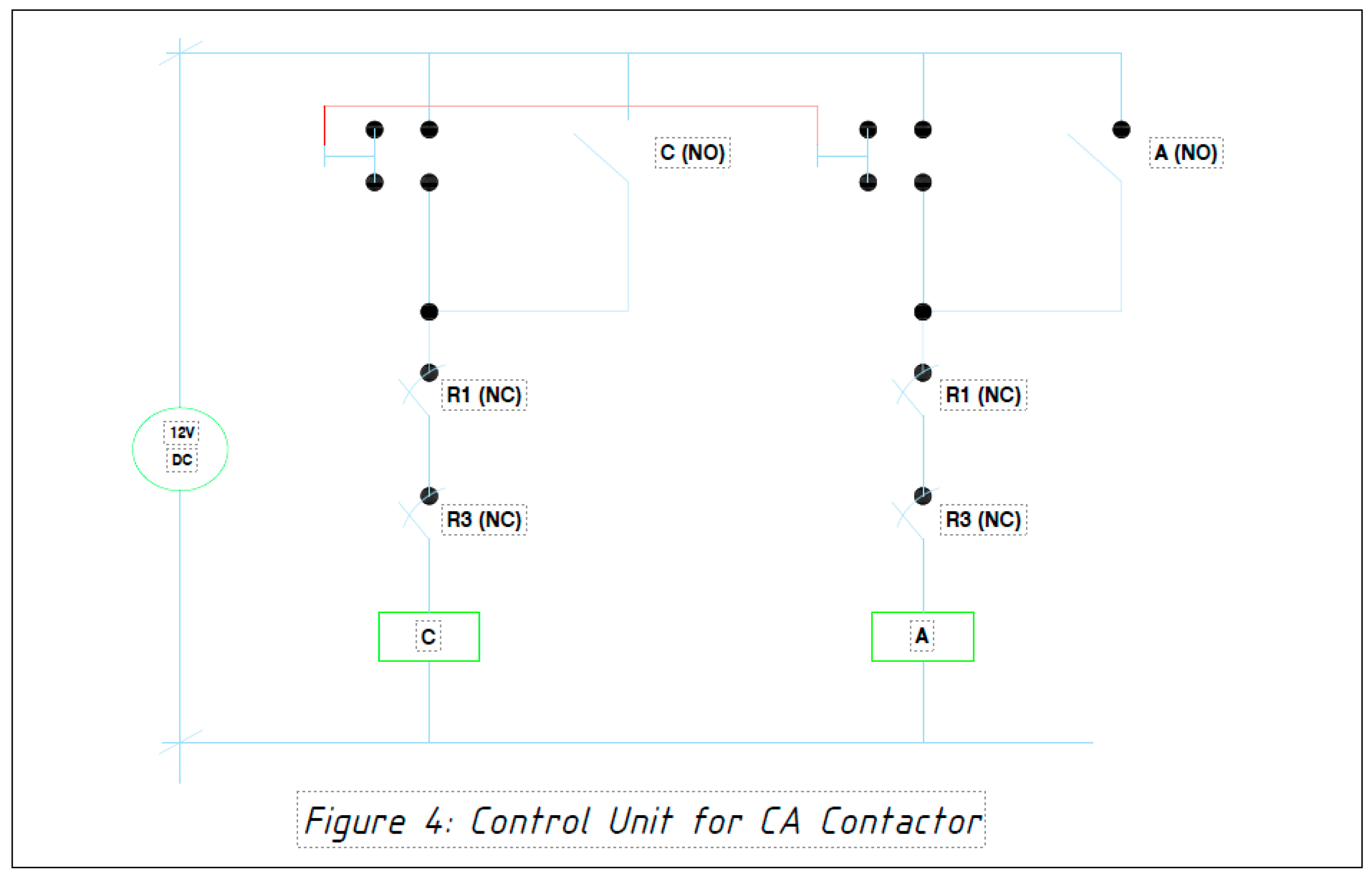
In the case for Phase AC the energization of the contactor A and C (phase AC) is by pushing the push button AC that supplies both the main A and C coil. The normally open auxiliary contact of A and C will hold the supply of the coil. For interlocking circuit, the normally open contacts of A and C which will energize the 12 volts auxiliary relay R2 to prevent the BC and AB control circuit to be closed. The contacts are in series as shown in Figure 5.
Figure 4.
Control circuit for CA contactor.
The design in this work is only limited to simulating the actual equivalent of relays and contact as the main contacts should be on medium voltage level (11, 13.8, 24, 33 KV). Figure 5 shows the interlocking circuit.
This interlocking circuit is wired or configured so that it prevents the relays from actuating at the same time. It means that the contactors cannot be energized or close simultaneously.
4. Results and Discussion
The result of proposed control of circuit of dynamic load balancer on three phase medium voltage distribution line is achieved using 3 - 220 volts electromechanical relay and 3 – auxiliary relay to represent the switching device on three phase medium voltage. The original control design was slightly modified as shown in Figure 6.
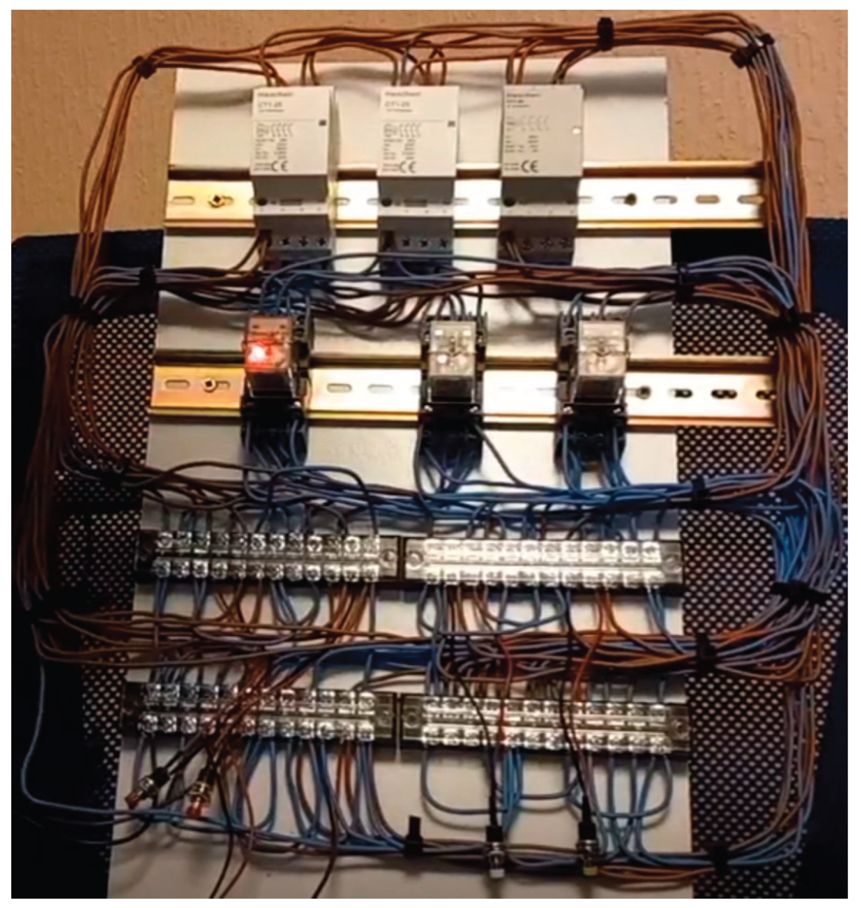
The momentary contact switch is now placed below the auxiliary contact before the A1 and A2 of the supply coil. For interlocking purposes, an auxiliary relay was utilized (R1, R2 and R3) to facilitate the desired switching combinations as per selection of the desired phase. The red colored push button represents the AB phase control, yellow for the CA and blue for the BC. Two momentary contact push buttons (NO) were used to imitate a single momentary contact with two normally open contacts. This design will need to be scaled to the desired voltage level. The traditional medium voltage recloser or sectionalizer have normally open or normally closed contacts that can be utilized to this application with integration on few relays for interlocking purposes. Figure 7 is the practical implementation of result.
As shown in the present-day single line diagram of DECORP, the number of single-phase transformers installed in the network is of considerable amount (45 single phase – 7 three phase bank). The duration of interruption needed to transfer the primary leads from and to desired phase will be about 30 to 45 minutes as per experienced opinion of Mr. Angelito Lora of DECORP (overhead line construction supervisor). With the new concept hardware, this interruption will be 5 seconds maximum and only the customers connected to the DT will be affected. The feeder interruption will no longer be required to execute the transfer of primary leads as this can be done by using the concept hardware with just momentary break switch and the transfer push button or using the SCADA capability to manipulate the transfer.
The control circuit is only to prelude the design of the entire hardware. The required BIL of the unit will need to be designed in relation to the system voltage it is intended to be utilized. The short circuit rating and other IEC or NEMA requirements should also be the benchmark in design specification of this new hardware. Design practice in single phase DT sizing normally from 25 KVA to 100 KVA, beyond this range the DT banking is done. With that as standard, the new hardware should be rated 100 KVA duty as this can future proof the system if the uprating of the DT will come. The simple requirement of balancing the system can be addressed by VR and OLTC. The additional option to dynamically transfer the loading of single-phase transformers will make the system operator more efficient and flexible. The possibility to develop SCADA integration of this concept hardware is of great potential as this will allow remote operation for the substation operator. The line personnel will no longer needed to change the primary leads; therefore, the resources can be utilized for other line maintenance or construction.
5. Conclusion
The control circuit of the proposed dynamic load balancer is the key to success of the concept. The ratings, current transformer (CT), potential transformer (PT), BIL, short circuit rating, limits switches, insulators insulation medium and the actual tank size will depend on which voltage level of application will this concept to be applied. The scalability could be from DT’s on distribution line to load side of customers with three phase and single-phase loads on their system connected together on one transformer bank.
The fundamental aim of this hardware is to lessen the switching or interruption time should the need to transfer a single-phase transformer is needed to balance the three-phase network. The one-hour average interruption time for a single transformer to be reconfigured to desired phase will be thing of the past, as this hardware will just a push of the button on local operation or click on the mouse if SCADA system can be exploited to this. Additional retrofitting is needed to achieve SCADA capability of the hardware, like to CT and PT and the communication and protocols to be used. This part of research will be the continuation for the development of the hardware.
The few seconds of interruptions could be negligible to some but not with few users like medical facilities or continuous manufacturing. The hardware full potential could be possibly used on fully hybrid loads with battery bank to absorb the burden during the switching to eliminate the interruptions. The utilization of existing network hardware to work with this new hardware will further improve network flexibility, system performance and reliability. Electricity network systems with complex interconnections will further develop and the future of smart grid is unfolding, and more challenges set by the government and the regulators are within the horizon.
References
- Energy Live News, 2022. Octopus Energy acquires Northern Irish heat pump manufacturer. [Online] Available at: https://www.energylivenews.com/2022/04/13/octopus-energy-acquires-northern-irish-heat-pump-manufacturer/ [Accessed 28 Sept 2023].
- Hamid Mohammadpour, B. A. E. S. M. K. K. , 2020. Optimized Dynamic Voltage Restorer (DVR) for. IEEE.
- London.gov.uk, 2016. London Plan. [Online] Available at: https://www.london.gov.uk [Accessed 16 September 2022].
- McMahon, S., 2020. Preparing for an accelerating decentralized energy system. [Online] Available at: https://www.ofgem.gov.uk/publication/preparing-accelerating-decentralised-energy-system [Accessed 19 September 2022].
- Ogunboyo Patrick Taiwo, R. T. I. E. D. , 2017. An Improvement of Voltage Unbalance in a Low. IEEE.
- Rao, S. , 1973. Switchgear and Protection. 1st ed. Delhi: Khanna Publishers.
- Vella, H. , 2022. Ten Steps to Net Zero. [Online] Available at: https://ieeexplore.ieee.org/stamp/stamp.jsp?tp=&arnumber=9450329 [Accessed 27 September 2022].
Figure 1.
Main relay contactor.
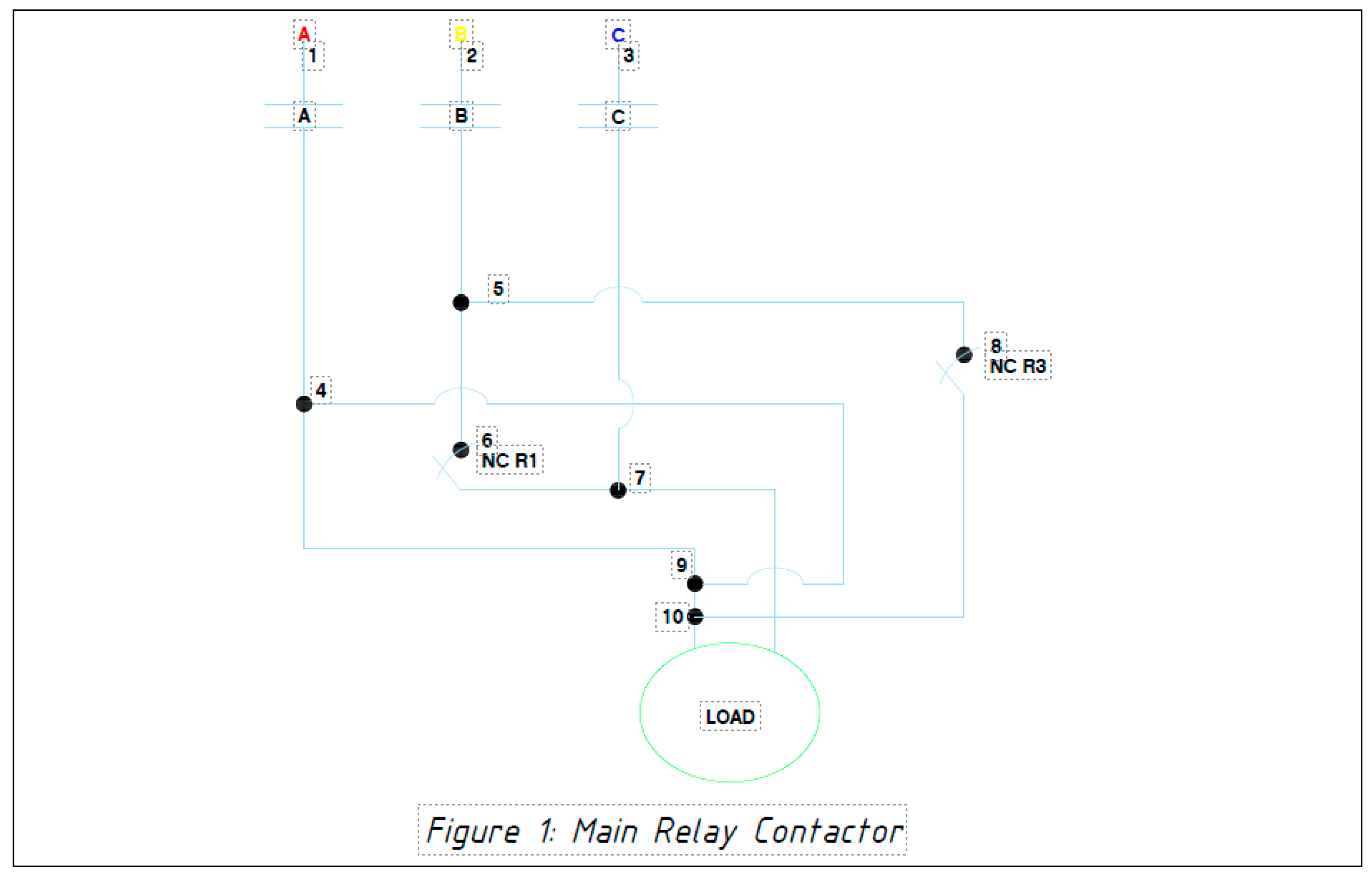
Figure 2.
Control circuit for BC contactor.
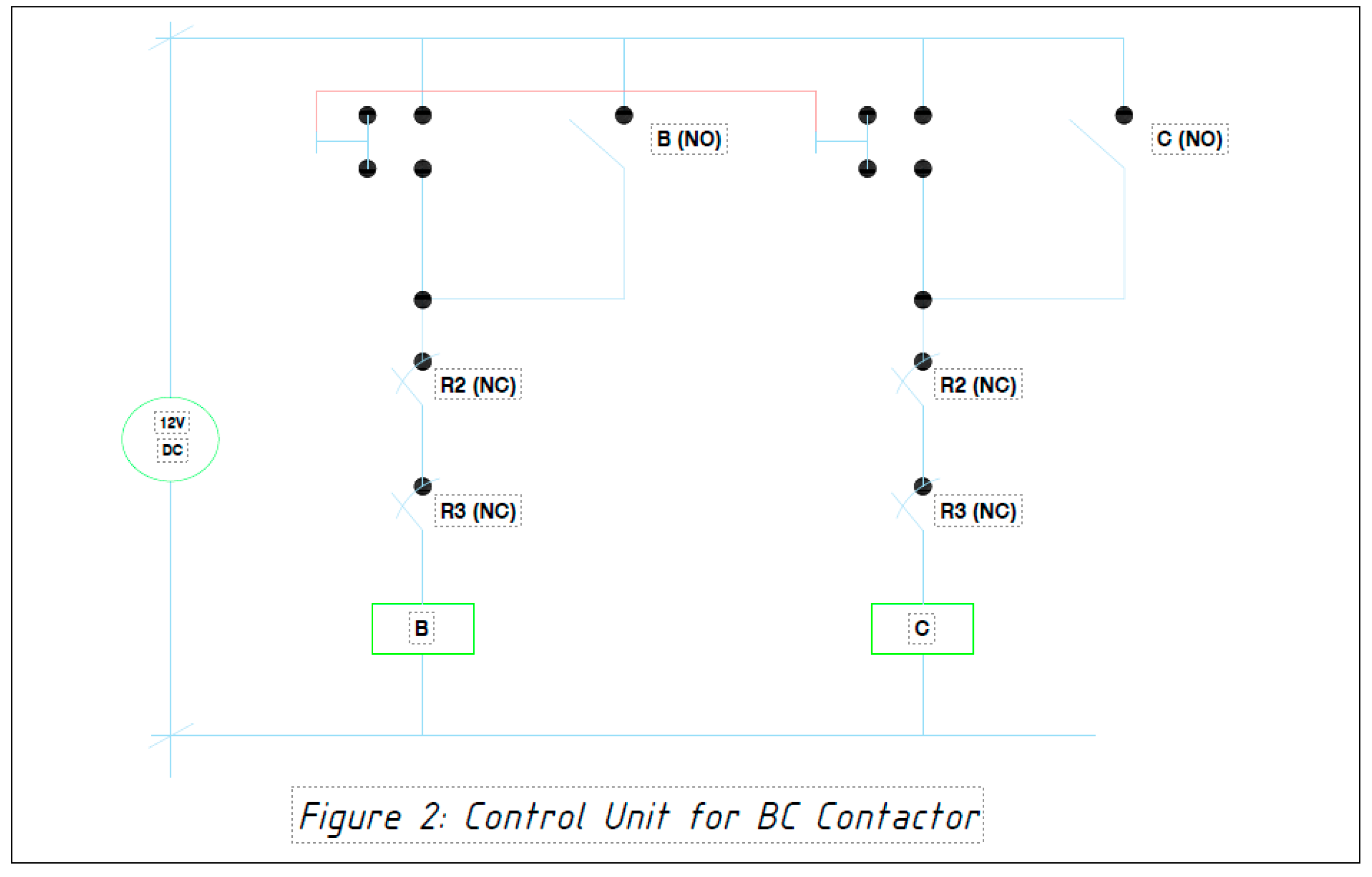
Figure 3.
Control circuit for AB contactor.
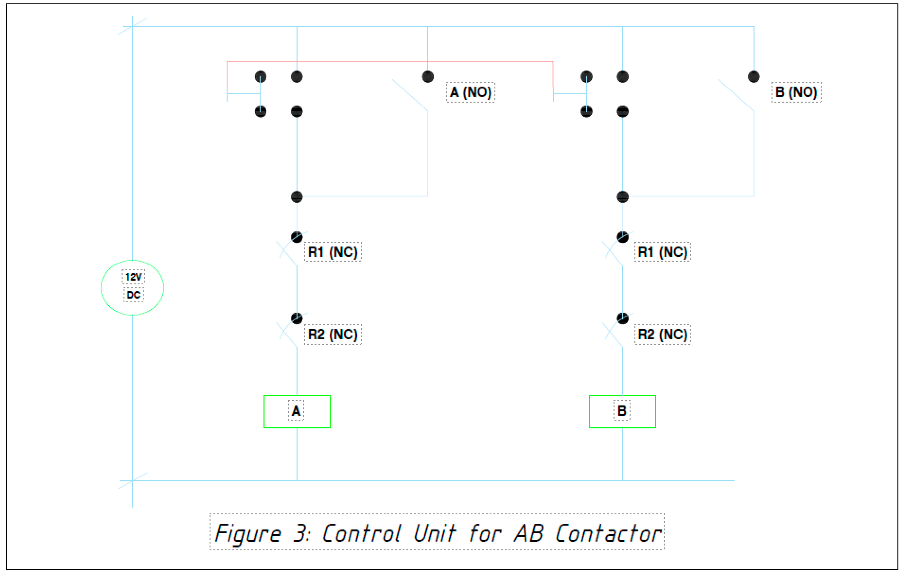
Figure 5.
The interlocking circuit.
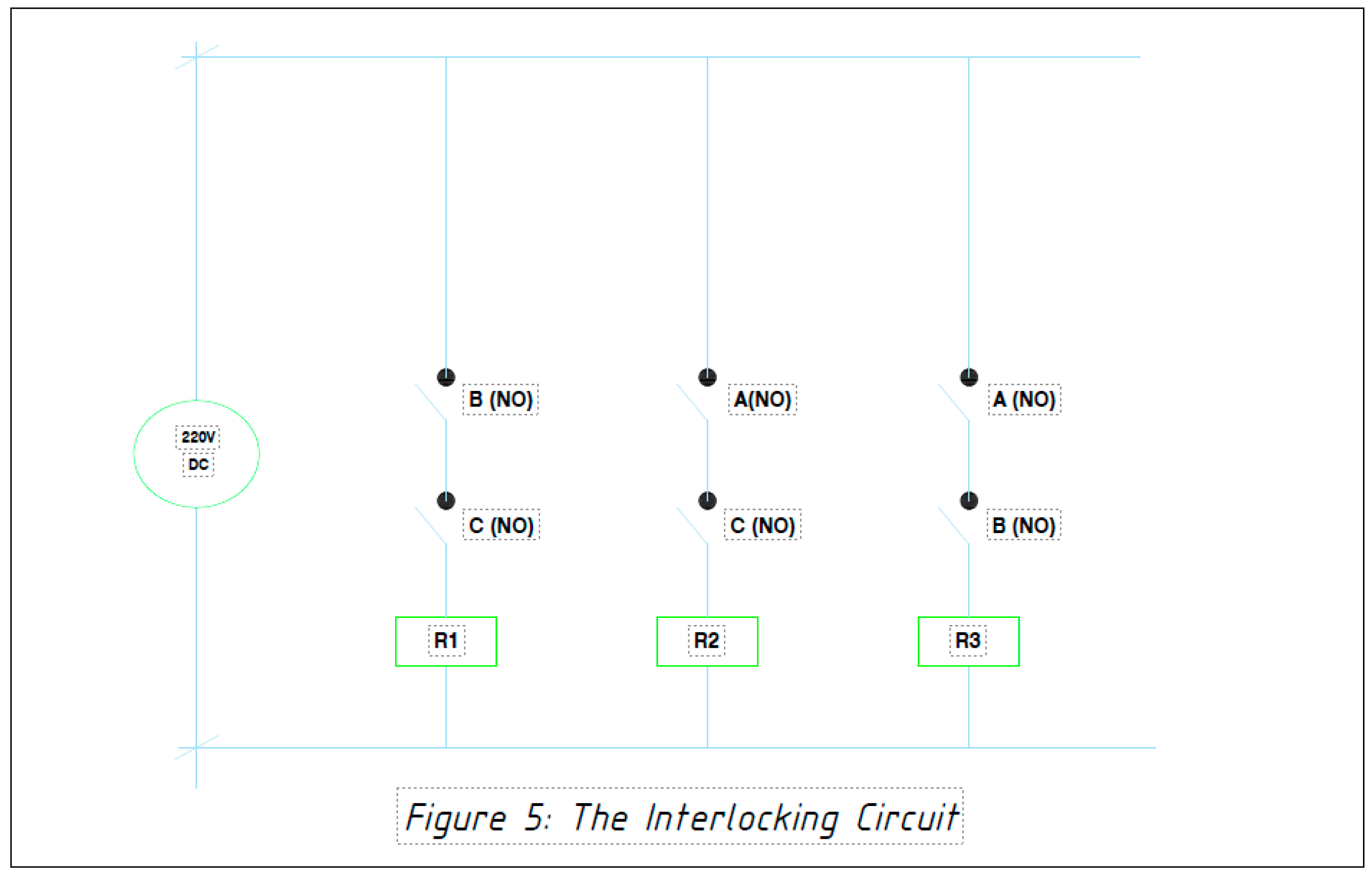
Figure 6.
Modified control unit.
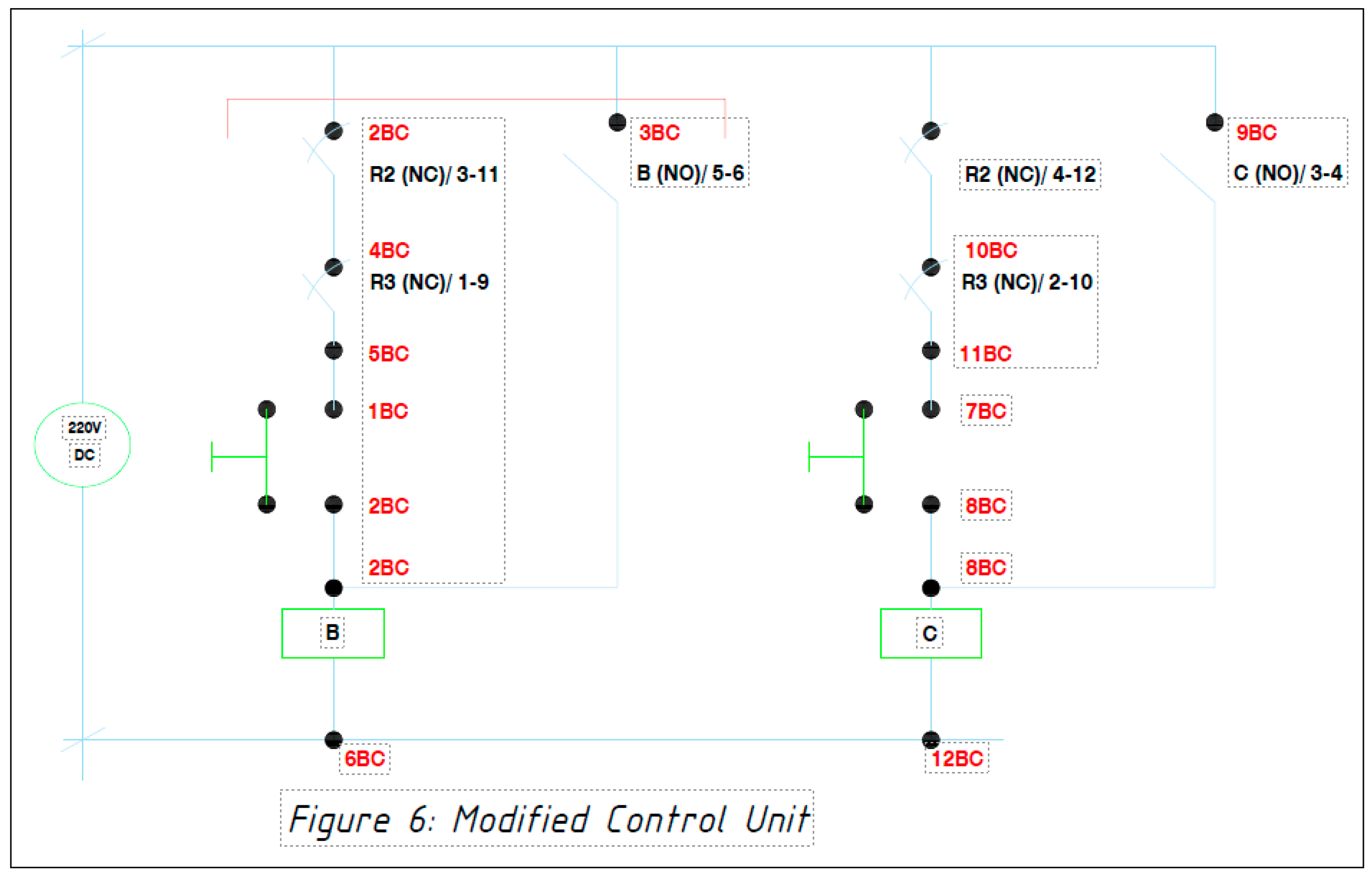
Figure 7.
Practical implementation of the designed control unit showing wiring and connections.
Disclaimer/Publisher’s Note: The statements, opinions and data contained in all publications are solely those of the individual author(s) and contributor(s) and not of MDPI and/or the editor(s). MDPI and/or the editor(s) disclaim responsibility for any injury to people or property resulting from any ideas, methods, instructions or products referred to in the content. |
© 2025 by the authors. Licensee MDPI, Basel, Switzerland. This article is an open access article distributed under the terms and conditions of the Creative Commons Attribution (CC BY) license (http://creativecommons.org/licenses/by/4.0/).
Copyright: This open access article is published under a Creative Commons CC BY 4.0 license, which permit the free download, distribution, and reuse, provided that the author and preprint are cited in any reuse.


