
Submitted:
07 September 2025
Posted:
09 September 2025
You are already at the latest version
Abstract
The computational fluid dynamics (CFD) computer language OpenFOAM is used to develop a magnetohydrodynamic (MHD) solver, which we applied to the Sakhalin pulsed solid-propellant plasma (SPP) power system, with a supersonic divergent channel. The proposed solver corresponds to the low magnetic Reynolds number (Rem), and it utilizes the scalar electric potential as the working variable for handling the electric aspect of the problem. After validation and verification, we use the solver to explore various aspects of the thermal, fluidic, and electric features of the problem. These include the pressure, temperature, density, velocity, Mach number, electric-current density, specific turbulent kinetic energy, and turbulence dissipation. After validation and verification, we use the solver to explore various aspects of the thermal, fluidic, and electric features of the problem. These include the pressure, temperature, density, velocity, Mach number, electric-current density, specific turbulent kinetic energy, and turbulence dissipation. Despite earlier studies about this Sakhalin pulsed magnetohydrodynamic generator (PMHDG), the current study provides novel comprehensive aspects and presents a useful MHD solver.
Keywords:
solid-propellant plasma
; solver
; PMHDG
; Sakhalin
; OpenFOAM
1. INTRODUCTION
A. BACKGROUND
Sakhalin is the name of a Russian island in Northeast Asia with a conspicuously elongated form, located near the Japanese island of Hokkaido 1,2. Sakhalin is also the name of a powerful pulsed magnetohydrodynamic (MHD) generator that has been widely used and studied in the USSR (Union of Soviet Socialist Republics), with a demonstrated electric output of 510 MW during one of its performed tests. The Sakhalin pulsed MHD generator (PMHDG) was fueled by a solid propellant (pyrotechnic powder), and it contained a single linear continuous Faraday-type supersonic channel, with a length of 4.5 m 3–5. The working medium for Sakhalin was hot-seeded weakly-ionized solid-propellant plasma (SPP). Continuous Faraday-type channels of MHG generators have two continuous electrodes placed opposite to each other, which is a simpler configuration compared to other electric connection designs 6,7; namely, the segmented electrodes (segmented Faraday) design, the linear Hall design, and the diagonal design 8. The Sakhalin was the world's most powerful PMHDG, with a theoretical peak electric output power of 600 MW (this reduces to about 400 MW with a connected matched load) 9. It was a self-contained system, not requiring connections to external supply sources 10. The mass of the solid propellant charge was about 6000 kg (6 tonnes). The electrodes (negative anode and positive cathode) were graphite. A possible solid propellant is a mixture of powders having 64% Mg (magnesium), 35% KNO3 (potassium nitrate), and 1% technological additives (percentages are mass-based), pressed to a density of about 1700 kg/m3 11. The propellant can also be based on metal aluminum, rather than metal magnesium 12. A small amount of alkali metal (cesium “Cs” or potassium “K”) is added to the solid propellant charge (the grain) to permit an appreciable level of ionization of the atoms of the seeded alkali metal (which changes phase to vapor at the high temperatures of the MHD channel) 13,14. Potassium (K) vaporizes at about 762 °C (1035 K), while cesium (Cs) vaporizes at about 682 °C (955 K) 15–17.
Pulsed magnetohydrodynamic generators (PMHDG) can be used for producing a powerful pulse of electricity, for a few seconds. PMHDG can be used in geoelectric prospecting, where the produced electric pulse allows for estimating the electric resistivity of underground formations at different depths 18–20. PMHDG may also be used to power electromagnetic rail launchers (railguns), where projectiles can be accelerated to speeds exceeding 2.5 km/s 21,22. PMHDG may also find applications in space systems 23,24 and rocket propulsion 25,26.
Besides Sakhalin, there were other solid-propellant plasma (SPP) PMHDG in the former USSR, but Sakhalin was by large the most powerful 27–29. A comparison of different SPP-PMHDG that existed in the former USSR is presented in Table I 30–32.
The table is not an exhaustive list. There were even additional SPP-PMHDG systems in the USSR, such as “Pamir”, and “Pamir-06”.
Aside from the pulsed mode of magnetohydrodynamic (MHD) generators, they can also operate in a continuous mode as a non-conventional topping power cycle in a dual-cycle thermal power plant 33–37. MHD generators have a special feature of favoring elevated temperatures, which boost the electric conductivity in a rapid nonlinear fashion 38–40. Other conventional power cycles (such as the Rankine-type steam cycle) can then be used as a bottoming cycle, where the enormous unexploited heat in the exhaust hot gases leaving the topping MHD power cycle can be used to generate steam that drives steam turbines, coupled with electromechanical generators, as happens in combined-cycle gas turbine (CCGT) power plants via a heat recovery steam generator (HRSG) to transfer heat from the higher-temperature topping gas cycle to the lower-temperature bottoming steam cycle 41–44.
The use of MHD generators, either pulsed or continuous, has an environmental advantage over fossil-fuel-fired power plants, where reducing the emissions of greenhouse gases (GHG) becomes possible, and this reduction helps in attenuating global warming 45–49. This possibility of GHG reduction when using MHD generators arises because the fuel and oxidizer combination in the case of combustion-plasma-based MHD generators can be selected such that the carbon dioxide (CO2) dominates the exploited plasma gases leaving the MHD generator, which facilitates its capture through the oxy-fuel carbon capture (OFCC) technology 50–53. The oxy-fuel technology is particularly attractive for MHD generators, because this specialized combustion technique largely raises the temperature of the combustion flame and the combustion products, thereby improving the electric conductivity of the thermal-equilibrium “hot” plasma gas, and thus increasing the electric output from the same volume flow rate of the plasma gas 54,55. In thermal-equilibrium “hot” plasma gas, atoms are ionized due to the temperature alone (unlike non-thermal “cold” plasma), and thus higher temperatures increase the electric output from the same volume flow rate of the plasma gas 56,57.
MHD generators also have the advantage of not having moving mechanical parts, which is unlike gas turbines, steam turbines, wind turbines, Stirling engines, and electromechanical generators that are commonly used in power generation 58–62. This simplicity of the design and the lack of complex fluid-structure interaction (FSI) and solid-solid contact eliminate the need for lubrication, bearing, and sealing elements 63–65. MHD generators are direct power extraction (DPE) systems, like solar photovoltaic (PV) modules and thermoelectric generators (TEG) modules, with no intermediate energy conversion processing needed 66–70.
One more advantage of MHD generators operating with seeded combustion plasma is their flexibility with regard to the combusted fuel. Unlike conventional internal combustion engines (ICE), either reciprocating ones used in automobiles or turbomachinery ones used in jet airplanes, the MHD generator can be viewed as an external combustion engine (ECE), because the combustion of the fuel occurs outside the MHD channel, which is the primary energy conversion component (extracting thermal, pressure, and/or kinetic energy from the fluid and converting the fluid energy into direct-current “DC” electricity) 71,72. Because the combustion products (flue gases) act mainly as a bulk high-speed medium that carries the ionized alkali metal species and the liberated charge-carrying electrons, a wide variety of fuels can be used in the plasma generator (PG) combustor unit 73–75. For example, green hydrogen (hydrogen produced through water electrolysis powered by renewable energy sources) may be exploited for this type of power generation 76–81. Gaseous fuels (such as natural gas) 82–85. Also, liquid fuels (such as kerosene) 86–88, and solid fuels (such as coal) are candidate sources of the plasma gases 89,90. Despite this flexibility, gas-fired and liquid-fired MHD generators have the advantage of not forming a slag layer (a layer of molten ash material that is solidified on walls) over the electrodes of the MHD channel 91–93.
B. OBJECTIVES
The first goal of this work is to present a proposed computational fluid dynamics (CFD) solver for continuous-electrode (continuous-Faraday) MHD channels, which is based on the OpenFOAM object-oriented programming (OOP) environment 94. OpenFOAM is a popular collection of open-source CFD solvers for a wide variety of problems, which include compressible flows, incompressible flows, laminar flows, turbulent flows, multi-phase flows, and reacting flows 95–99. OpenFOAM has been used in many applications in fluid dynamics 100–102, combustion 103, fluid-structure interaction (FSI) 104, and heat transfer 105. OpenFOAM is based on the finite volume method (FVM) for discretizing the governing equations of the flow, while attempting to enforce local conservation of mass, momentum, and energy at the level of a single computational cell (a single finite volume) 106,107. The proposed MHD channel solver in this study is a valuable tool in the computer-aided design (CAD) of MHD channels with continuous electrodes, either operating in a pulsed mode or operating in a sustained mode. The solver may be further extended by the interested readers to add desired design alterations or explore different operating conditions such that one or more of the performance outputs can be controlled and optimized 108,109. For example, the influence of the area cross-section profile of the supersonic channel (as a control variable) on the electric power output, the role of the externally applied magnetic field (applied magnetic-field flux density) on the plasma streamlines, and the use of seed alkali injection to boost the electric conductivity of the expanding plasma gas may be investigated in other studies by extending the model provided in this work 110–112.
The second goal of this work is to present comprehensive results of three-dimensional computational fluid dynamics (CFD) modeling of the channel of the Sakhalin pulsed magnetohydrodynamic generator with solid-propellant plasma (PMHDG-SPP). Unlike various reported results in the literature, the current study shows a large number of three-dimensional and sampled one-dimensional variations of fluid fields and electric fields, as well as aggregate system-level scalar values. All these results help in understanding better the complex phenomena inside the channel. CFD modeling and post-processing of its results are very beneficial in this regard, due to the digital non-intrusive probing at any spatial location of the simulated domain. Although Sakhalin is an old system, it remains an exemplary MHD study case due to the details reported about it. Therefore, this goal is viewed as a beneficial contribution to the MHD generation field, as it can guide future attempts to construct a similar system, either pulsed for geological research or sustained for electric power generation.
The third goal of this work is to provide a brief review of former solid-propellant plasma (SPP) pulsed magnetohydrodynamic generators (PMHDG).
This study contributes to regaining interest in MHD power generation, aiming for it to be further investigated as a potential way for diversifying the energy mix locally and globally 113–116, expanding the oxy-combustion carbon capture technology, benefiting from an exceptionally high volumetric power density 117–119, utilizing concentrated direct power extraction, facilitating the process of electrification 120–123, and pursuing unconventional energy solutions to help in achieving net-zero emissions 124. Furthermore, the study can be helpful for educational purposes in physics, electric power engineering, numerical methods, or computer programming at the higher education level 125–130.
2. RESEARCH METHOD
This section aims to describe the mathematical, computational, and geometric settings of the proposed simulation modeling for generic Faraday-type magnetohydrodynamic (MHD) channels having continuous electrodes 131.
By being continuous electrically-conducting electrodes (made of metal or graphite for example), either electrode is assigned a single voltage (a single electric potential). In this study, the anode is assigned a reference voltage of zero. Thus, the “cathode voltage” here refers to the voltage difference between the higher cathode voltage and the lower anode voltage.
A. FLUID FLOW EQUATIONS
We present here the governing partial differential equations for the plasma as a homogeneous compressible turbulent gas. These equations are extended versions of the classical Favre-averaged Navier-Stokes equations (FANS), by adding supplementary terms that mathematically account for the electromagnetic effects on the electrically-conductive plasma. The Favre-averaged Navier-Stokes equations are commonly referred to as RANS (Reynolds-averaged Navier-Stokes equations), although RANS strictly applies to incompressible (constant-density) fluids, whereas the Favre-averaged Navier-Stokes equations are extension of RANS to compressible (variable-density) fluids, which pertain to MHD generators operating on combustion plasma 132–135. The RANS formulation utilizes simple (unweighted) time averaging, whereas the formulation FANS formulation utilizes density-weighted (mass-weighted) time averaging 136–139.
The scalar mass conservation equation (the continuity equation) of the plasma gas is identical to the one governing ordinary gases (not electrically-conducting). The presence of a magnetic field and the existence of an electric conductivity of the plasma do not influence the mass conservation law of that plasma. Therefore, the mass conservation equation is
where is the mass density of the plasma gas, is the time, is the velocity vector of the plasma (this is absolute velocity, relative to a fixed laboratory frame), and is the divergence operator 140,141.
The vector linear momentum conservation equation for the plasma flow within the MHD channel is an extension of the conventional linear momentum conservation equation for a non-reacting single-phase compressible turbulent flow, where a source term is added to account for the Lorentz force per unit volume, acting on the charged particles within the plasma gas as a body force exerted on a unit volume of the plasma flowing inside the MHD channel 142,143. To explain the cause of this source term, it should be noted that any current-passing electrically-conducting medium that is in a translational motion while subject to a magnetic field experiences an induced force called the Lorentz force, which is perpendicular to both the translational motion and the applied magnetic field 144,145.
Therefore, the extended plasma’s linear momentum equation within the MHD channel is
where the operator represents the outer product of two vectors, is the pressure (absolute pressure), is the pressure gradient vector, is the viscous shear stress tensor, is the turbulent shear stress tensor, is the electric-current density (the current density) vector, is the magnetic-field flux density (the magnetic field) vector, and the right-hand side term is the added source term (the Lorentz force per unit volume of plasma) 146–149.
The viscous shear stress tensor is a deviatoric (traceless) tensor, modeled using the following constitutive relation 150,151:
where is the absolute viscosity (the dynamic viscosity) of the plasma gas, is a tensor representing the gradient of the velocity vector, is the transpose of , and is the identity tensor 152,153.
The turbulent (or Reynolds) stress tensor is modeled using the following gradient transport hypothesis (eddy-viscosity turbulence modeling) 154:
where is the turbulent viscosity, is the turbulent kinetic energy per unit mass, and the spherical tensor appears due to the eddy-viscosity turbulence modeling 155,156.
The sum of the laminar viscosity (the molecular viscosity) and the turbulent viscosity (the eddy viscosity) is the effective viscosity () 157,158
Therefore, the sum of the viscous stress tensor and the turbulent stress tensor can be expressed as 159,160
It is worth mentioning that the tensor
is the deviatoric (traceless) component of the velocity gradient tensor , which has a trace of , and this trace quantity vanishes for incompressible fluids, but it is not zero here in the presented MHD plasma low model 161–164.
The scalar equation of energy conservation is written here using the total (stagnation) specific internal energy, , as the dependent variable, instead of the temperature . This form is suitable for high-speed gases, as encountered in open-cycle MHD channels 165–168,168,169. As with the case of the vector momentum equation, the scalar energy equation has a source term that is not present in the ordinary form (for non-electrically-conductive gases). This source is the power (per unit volume of plasma) extracted from the plasma and converted into electric power (per unit volume of plasma) to an external electric load connected to the electrodes of the MHD channel.
Thus, the extended energy equation for the plasma gas is
where is the effective thermal conductivity (accounting for both laminar/molecular effect and turbulent/eddy effect in heat conduction), is the effective diffusion heat flux vector (expressed in terms of the temperature gradient according to Fourier’s law), is the viscous-stresses power (rate of work by the plasma) per unit plasma volume due to viscous stresses, and is the source term due to the electric properties of the plasma 170,171. The vector is the electrostatic field (caused by the voltage difference between the MHD electrodes due to the externally applied load “if applicable” or due to the external electric circuit being open “the electrodes are not electrically connected electrically”). The vector field is an applied electric field on the plasma due to the voltage difference at the electrodes surrounding it, and these electrodes (grounded anode and positive cathode) are used to power an external electric load, thus we also refer to this electric field as the electrostatic field. The vector field is not directly dependent on the motion of the plasma, which explains the name “electrostatic”. The vector field can even be externally applied and ma manually controlled, by connecting the electrodes of the MHD channel to a DC power source (instead of an electric load). On the other hand; another electric field is induced due to the translational motion of the electric-conductive plasma gas with a velocity vector within an applied magnetic magnetic-field flux density ; this induced electric field is , and it can be referred to as an “electrodynamic” field. The load electric field is irrotational (as per Coulomb’s law) 172–174. This means
The source term actually has a negative value (the electrostatic field vector is directed against the electric-current density vector), making this source term act actually as an energy sink, which is the valid interpretation of it as an expression of the process of extracting energy from the plasma flow and supplying it as electric energy to an external electric load. In the idealized (most simplified) case of one-dimensional (unidirectional) constant plasma velocity through a constant-cross section MHD channel, one-dimensional (unidirectional) constant applied magnetic field and one-dimensional (unidirectional) constant electrostatic field being perpendicular to the parallel electrodes (from the grounded anode to the positive cathode), and with the three fields are mutually orthogonal to each other; this energy source term reduces to . Thus, it is actually an energy sink term with a magnitude of , where and reduce to scalar values (but the current density is from the anode to the cathode, while the electrostatic field is from the cathode to the anode) 175.
The total specific internal energy is the sum of the static specific internal energy and the specific kinetic energy . Mathematically, this is expressed as 176
The static specific internal energy is related to the static specific enthalpy as 177,178
Likewise, the total specific internal energy is related to the total specific enthalpy as 179,180
This means
The ideal gas law (ideal gas equation of state) is also needed in the MHD model, as an algebraic relation between the absolute pressure , absolute temperature , and density . The ideal gas law is not affected by the electric characteristic of the weakly-ionized seeded combustion plasma, which is still treated as a gas thermodynamically. The ideal gas law has the form 181,182
where is the specific gas constant for the plasma gas, which is related to the universal (molar) gas constant and the plasma molecular weight as 183
The value of is 8.314 J/(mol.K) or 8,314 J/(kmol.K) 184,185. If the plasma is treated as a mixture of two of more gaseous species, then the molecular weight depends on the local chemical composition of the plasma (at a given computational cell) as 186
where is the mole fraction of the ith gaseous species in the plasma gas mixture (such as carbon dioxide CO2 or water vapor H2O), is the molecular weight of that ith gaseous species, and N is the number of gaseous species in the plasma gas mixture.
B. ELECTRIC FIELDS EQUATIONS
In the previous subsection, it was shown that three electromagnetic vector fields are needed in order to integrate the system of partial differential equations governing the density, velocity, and the total specific internal energy of the plasma flow within the MHD channel. These three electromagnetic vector fields appear in the two source terms that arise in the extended vector momentum equation and the extended scalar energy equation. These three needed electromagnetic vector fields are (1) the electric-current density vector (or simply the current density) , (2) the magnetic-field flux density vector (or simply the magnetic field) , (3) and the electrostatic vector field .
The magnetic-field flux density is a specified applied field. Thus, in the proposed MHD model here, only the current density field and the electrostatic field need to be estimated.
The approach proposed here for handling the electric aspect of the problem utilizes a scalar electric potential field as a working variable that is directly solved for, and then its solution is used to indirectly compute the fields and .
The electric potential scalar field is related to the electrostatic vector field as follows:
Thus, the gradient of the electric potential is the electrostatic field, but in the opposite direction. The above mathematical relation is made possible given that the electrostatic field is irrotational 187–190.
The electric potential is governed by a Poisson-type parabolic partial different equation as 191
where is an effective electric conductivity tensor for the plasma gas. For the case of unidirectional magnetic-field flux density in the direction only (thus, ), with being the magnitude of that magnetic-field flux density (which can be a function of space rather than being a uniform constant), the effective electric conductivity tensor has the following form:
where is the scalar electric conductivity of the plasma, and is the dimensionless Hall parameter (electron’s Hall parameter), which is the product of the electron mobility and the magnitude of the applied magnetic field 192–194. Therefore,
The effective electric conductivity tensor is used to express the generalized form (the vector form) of Ohm’s law for the electrically-conductive plasma, as 195,175,196
It should be noted that the vector is the net electric field acting internally on the plasma (as an electrically-conductive medium having its own internal electric resistivity), and it accounts for both the electrostatic field and the electrodynamic field . As an illustrative analogy with a simple battery-lamp circuit, the field is likened to the battery voltage, the field is likened to the voltage drop across the lamp, and the field is likened to the voltage drop across the battery itself due to its internal electric resistance. Furthermore, the absolute value of the energy equation source term can be likened to the power dissipated in the lamp. In the plasma’s energy equation, this term has a negative value because, for the plasma, it is power extracted (removed).
It should also be noted that the proposed solution method for the electric fields assumes that the magnetic-field flux density is fixed in time (but it does not need to be fixed in space), and thus the magnetic-field flux density is not affected by the plasma flow. This corresponds to the low magnetic Reynolds number approximation 197,198. The magnetic Reynolds number (Rem) is a dimensionless quantity that helps in quantifying the interaction between the moving plasma and the magnetic field 199,200. Under large magnetic Reynolds numbers (Rem >> 1), the magnetic field lines can be likened to elastic bands that are frozen into the electrically-conductive plasma 201. The velocity of the plasma induces a secondary induced magnetic-field flux density , which is added to the applied magnetic-field flux density , making the total magnetic-field flux density actually dependent on the plasma flow. This additional flow-dependent magnetic-field flux density then affects the plasma velocity through the source term in the plasma momentum equation, presented in (2). Thus, at high magnetic Reynolds numbers, a two-way coupling exists between the magnetic-field flux density seen by the traveling plasma and the velocity field of that plasma. On the other hand, under small magnetic Reynolds numbers (Rem << 1), the movement of the plasma has a negligible effect on the magnetic-field flux density acting on it. Therefore, it is reasonable in that case to treat the magnetic-field flux density acting upon the plasma as the fixed externally-applied field only. This means that the low magnetic Reynolds number approximation treats the coupling between the magnetic-field flux density and the plasma motion as having a one-way direction, with the externally-applied magnetic-field flux density affecting the motion of the plasma while the induced current density within the moving plasma does not distort the magnetic field through producing an additional induced one 202. The low magnetic Reynolds number (low-Rem) approximation is also called an “inductionless” approximation 203. On the other hand, when the induced magnetic-field flux density is accounted for, this corresponds to a “self-excitation” or “self-excited” system 204.
Mathematically, the magnetic Reynolds number (Rem) is defined as
where is a reference magnetic permeability. The magnetic permeability of vacuum (the permeability of free space or the magnetic constant) is a universal constant with the exact value of 4π × 10–7 H/m 205–207. In the above equation defining Rem, is a reference electric conductivity of the electrically-conductive medium, is a reference scalar speed for the electrically-conductive medium, and is a reference length relevant to the geometric scales of the problem.
The definition of the magnetic Reynolds number (Rem) in (21) can be reformulated as
where the product has the dimension of (area/time), which is the same as the momentum diffusivity (the kinematic viscosity) for fluids. Therefore, the quantity may be called a reference “magnetic diffusivity”, and assigned the symbol that resembles the symbol used for designating a reference momentum diffusivity (a reference kinematic viscosity) in fluid mechanics 208.
Equation (22) thus can be written as
The above form is very similar to the one used for defining the conventional Reynolds number (Re) in fluid mechanics applications, which is 209,210
This conventional Reynolds number (Re) in fluid mechanics is used as a nondimensional criterion to infer whether the fluid flow is expected to be in a laminar (regular and smooth) regime or a turbulent (irregular with a lot of mixing) regime. However, unlike the magnetic Reynolds number (Rem); the threshold of regime transitioning for the conventional Reynolds number (Re) tends to be much larger than unity, and this threshold is dependent on the type of flow (for example, internal flows inside a cylindrical pipe have a lower threshold than external flows over the same cylindrical pipe).
The low magnetic Reynolds number (low-Rem) approximation is relevant in MHD generators, and it is adopted in the proposed MHD model here 211,212. To demonstrate this relevance, we consider a representative situation of a weakly-ionized plasma gas for MHD channels, formed by seeding hot air at 3,000 °C (3,273 K) with a small amount of potassium vapor (2% fraction). Under a reasonable reference length of 1 m and a reasonable reference speed of 1,000 m/s, the magnetic Reynolds number (Rem) is near 0.13 only, while the conventional Reynolds number (Re) is about 3.5 × 10⁶ 213. For the Sakhalin pulsed MHD generator, the induced magnetic-field flux density is small compared to the external magnetic-field flux density , with the peak of (about 0.19 T) being less than 10% of the peak of (about 2.1 T). This induced magnetic-field flux density causes the overall magnetic-field flux density (the sum of and ) to be less than the externally applied at the first region of the channel (nearly in its first half), but more than the externally applied in the second region of the channel (nearly in its second half), and the alteration due to are smallest near the middle of the longitudinal dimension of MHD channel (around = 2.25 m). The influence of the induced on the estimated electric power generation is only 2.5% 214. So, our low magnetic Reynolds number (low-Rem) approximation is considered suitable, despite that the magnetic Reynolds number (Rem) for the Sakhalin PMHD generator is not very small compared to unity, but it is still less than one (about 0.5).
For a solid conductor, the generalized form (vector form) of Ohm’s law, as presented in (20), reduces to the classical scalar form of Ohm’s law, which is
where is the electric current, is the voltage difference (voltage drop across the electric load), and is the electric resistance of the electric load.
Using (18) in (20), and expanding the resulting expression from a vector equation into three scalar equations gives the following three Cartesian components of the electric density vector, ]:
where are the three Cartesian components of the plasma velocity vector , and are the three Cartesian components of the electrostatic vector . Thus, . and . It can be noticed that while there is a coupling between and , they are decoupled from . This decoupling is a result of assuming the magnetic-field flux density to be unidirectional, thus in the proposed MHD model.
The Poisson equation (17) for the electric potential has the electric potential in the left-hand side only, which is treated with implicit discretization, while the right-hand side has the flow velocity, which is discretized explicitly.
When the electric potential is obtained by integrating the Poisson equation (17) numerically, a Dirichlet boundary condition (a first-type boundary condition) is applied at the anode (the top MHD boundary), by enforcing the value of to be zero, which is an arbitrary value that represents electric grounding 215–217. Another Dirichlet boundary condition is applied at the positive cathode electrode (the bottom MHD boundary), by enforcing the value of there to be equal to the aimed value for the MHD operation (the target voltage drop needed for powering the external electric load, or the target open-circuit voltage if no load is connected). Therefore, the two boundary conditions for the electric potential at the two electrodes are
where is the target voltage difference across the electrodes and thus across the external connected load (or the open-circuit voltage).
For the two other boundaries of the MHD channel (the non-electrically-conductive walls), a Neumann boundary condition (a second-type boundary condition) is applied, which has the form 218–220
where is a unit normal vector pointing perpendicularly away from the MHD boundary wall (as if leaving the channel laterally).
After obtaining the electric potential field , the electrostatic field is computed as the negative gradient of using (16), which is repeated below for a convenient flow of the analysis.
Finally, the generalized Ohm’s law is used to compute the electric-current density according to (20), which is repeated below for a convenient flow of the analysis.
C. GEOMETRY AND MESH OF THE SAKHALIN MHD CHANNEL
The geometry and operational settings for the modeled Sakhalin MHD channel are illustrated in Figure 1. The bulk flow direction of the supersonic plasma is along the -axis. The unidirectional magnetic field depends only on the axial distance () from the channel inlet, and the range of is from 0 to 4.5 m. The anode is the upper surface of the channel (having positive linearly-increasing coordinates), while the cathode is the lower surface of the channel (having negative linearly-decreasing coordinates). The width of the channel (along the Z direction) is constant, with a value of 1 m. The height (along the Y direction) of the channel increases from 0.9 m at the inlet to 1.6 m at the outlet.
Projected views (front view and top view) of the MHD channel are provided in Figure 2. The front view is a trapezium (a trapezoid), while the top view is a rectangle.
The spatial discretization of the Sakhalin MHD channel is illustrated in Figure 3. Due to its geometric simplicity, the channel is discretized spatially as a single block, with a total of 376,380 hex cells (hexahedral computational cells). We used 180 cells along the axial dimension (the length), 51 cells along the vertical dimension (the height), and 41 cells along the lateral dimension (the width). Hexahedral (structured) meshes tend to be favored over tetrahedral (unstructured) meshes due to the higher accuracy, and the ability to have a larger aspect ratio 221–223. Similarly, in two-dimensional problems, quadrilateral cells are computationally preferred over triangular cells 224,225. Therefore, when possible, a tetrahedral mesh may be limited to complex geometries that cannot be represented well through hexahedral mesh elements. In our CFD simulation of the Sakhalin MHD channel, tetrahedral cells were not necessary.
Our selected spatial discretization makes each cell nearly a cube (cells have a comparable size of their edges, near 0.025 m), and this rough regularity in the mesh is preferred in CFD simulations compared to highly skewed or stretched cells 226,227. Furthermore, our selection of an odd number of cells for the height (51 cells) and the width (41 cells) ensures that the longitudinal centerline of the channel coincides with a sequence of cell centers, which are also equally spaced. This is helpful because we sample the simulation results along that longitudinal centerline, which starts from the coordinates [0,0,0] and ends at the point [4.5,0,0]. Thus, exact cell-center values are readily available for sampling, without approximating interpolation.
D. EMPIRICAL EXPRESSIONS FOR SAKHALIN
The previous mathematical description of the governing equations and computational modeling for the MHD plasma is not restricted to the Sakhalin pulsed magnetohydrodynamic generator (PMHDG). However, a number of thermofluidic and electromagnetic properties appear in these governing equations, which should be modeled in the computational fluid dynamics (CFD) simulations using customized submodels 228–231. Such properties include the specific heat capacity at constant pressure , the magnitude of the unidirectional magnetic-field flux density the Hall parameter , and the scalar electric conductivity .
The Sakhalin PMHDG has empirical expressions published in the literature that describe the aforementioned four quantities 232. Such expressions are listed in Table II. In addition, the same table lists other operational conditions used in our simulation based on published data in the literature.
For the magnitude of the magnetic-field flux density , the expression listed in the table is our seventh-degree polynomial fitting, which we obtained using the (curve_fit) function of the (optimize) package for optimization and root finding, provided with the (SciPy) open-source Python library 233–235. The function (curve_fit) utilizes a non-linear least squares method. Our proposed fitting function is visualized in Figure 4.
E. COMPUTATIONAL SETTINGS
As with other computational fluid dynamics (CFD) simulations, a number of choices need to be made with regard to discretization schemes and/or numerical parameters. In this subsection, we cover this aspect of the OpenFOAM model presented here for magnetohydrodynamics (MHD) channels by listing some configuration settings adopted in the simulation in Table III.
The simulated time of 0.04 s was selected because the solution reached a quasi-steady state, with negligible transience. Although the governing equations are unsteady, the simulation solution reached a stable stage.
OpenFOAM Code Lines
We provide below code lines from the proposed OpenFOAM magnetohydrodynamic (MHD) solver, based on our mathematical description provided earlier.
For example, the first part of these code lines shows how the Poisson equation (17) for the electric potential is solved using the high-level OpenFOAM programming language, through an iterative loop with (nCorr) iterations. In the code, the electric potential is assigned the variable name (phi_e).
The remaining parts of the code lines show how the scalar mass conservation equation is solved, followed by the vector momentum equation, and finally the scalar energy equation 255,256.
for (int i = 0; i < nCorr; i++)
{
fvScalarMatrix phiEqn
(
fvc::div( sigmaEff & (U ^ B) ) - fvm::laplacian(sigmaEff,phi_e)
);
phiEqn.relax();
phiEqn.solve();
E = -fvc::grad(phi_e);
J = sigmaEff & ( E + (U^B) );
lorentzForceDensity = J ^ B;
powerDensity = E & J;
}
solve(fvm::ddt(rho) + fvc::div(phi));
solve
(
fvm::ddt(rho, U) - fvc::ddt(rho, U)
- fvm::laplacian(muEff, U)
- fvc::div(tauEffExplicit)
);
surfaceScalarField TauEffDotUDotSf
(
(
fvc::interpolate(muEff)*mesh.magSf()*fvc::snGrad(U)
+ (mesh.Sf() & fvc::interpolate(tauEffExplicit))
)
& (frac_ap*U_ifAllFluxesOut + frac_am*U_ifAllFluxesIn)
);
solve
(
fvm::ddt(rhoE)
+ fvc::div(phiE_pU)
- fvc::div(TauEffDotUDotSf)
- powerDensity
);
e = rhoE/rho - 0.5*magSqr(U);
e.correctBoundaryConditions();
volScalarField kEff("kEff", thermo.Cp()*turbulence->alphaEff());
solve
(
fvm::ddt(rho, e) - fvc::ddt(rho, e)
- fvc::laplacian(kEff, T)
);
rhoE = rho*(e + 0.5*magSqr(U));
3. VALIDATION AND VERIFICATION
After presenting the mathematical/computational formulation of the OpenFOAM solver developed for handing continuous Faraday channels in MHD generators, this section is provided to compare some results we obtained using the solver with values previously published in the literature, and this is a validation step for our CFD solution of the Sakhalin pulsed magnetohydrodynamics generator (PMHG), through external benchmarking. In the verification step, we perform internal benchmarking by comparing the CFD solution at the nominal spatial and temporal resolutions with another CFD solution using the same solver but at finer spatial and temporal resolutions; this verifies the ability of the CFD model to converge at the nominal resolutions 257–259.
Before presenting the validation step; we point out that due to the uncertainty in reported data of the Sakhalin PMHDG where a range for a variable is reported, rather than a single value for it (such as the mass flow rate), the discrepancy of some reported operational characteristics (such as the MHD channel inlet velocity), the time-unsteadiness nature of the actual problem, our simplification introduced in the inlet conditions, and the empirical fitting functions used in modeling some parameters; we do not aim at achieving a close quantitative agreement with the literature information 260. Instead, we seek to obtain values of aggregate quantities that are comparable to those reported by others. We consider three key benchmarking quantities for the validation step, as summarized in Table IV. Based on the acceptable small deviation in this table, our simulation is considered valid.
Table V summarizes the verification step for our CFD simulation of the Sakhalin PMHDG channel using the proposed OpenFOAM solver. In this step, we generated an internal benchmarking solution using the same proposed OpenFOAM solver but at a finer spatial resolution and a finer temporal resolution. This auxiliary fine-resolution solution acts as a higher-fidelity reference to assess the nominal (the solution obtained with the nominal resolutions). Based on the observed small changes in the compared characteristic of the MHD channel, as shown in the table, our verification step is considered successful, and our nominal OpenFOAM CFD solution is considered satisfactorily resolution-independent. All the remaining results in this study correspond to the nominal resolutions (which are 376,380 cells and 5 × 10⁻⁶ s time-step).
The above verification table also has indications about the validity of our OpenFOAM model, through the correct sign of the -component of the volumetric Lorentz force density (force per unit volume), which is pointing from the lower cathode to the upper anode for our case where the plasma’s bulk motion is in the positive direction, and the magnetic-field flux density is unidirectional in the positive direction. The Lorentz force vector on a general electrically charged particle with a positive charge , when this particle is carried with the plasma gas (moving at the same bulk velocity ) is 265
Although electrostatic field reduces or alters the electrodynamic fields , the resultant overall electric field is like electrodynamic fields in terms of pointing vertically down (in the negative direction, from the upper anode to the lower cathode).
Because the effective mobile charge carriers in the plasma are the negatively-charged electrons (not the positively-charged seed ions), the charge is actually negative, and thus the Lorentz force actually points upward, and this is in agreement with our CFD predictions 266,267.
The finding that the averaged electric-current density vector is pointing opposite to the averaged Lorentz force vector is also a favorable indication that the CFD model is able to predict correct vector fields. While the collected conventional electric current flows externally through the electric load from the positive cathode to the grounded anode, the electron electric current flows externally in the opposite direction from the grounded anode to the positive cathode. In the presented OpenFOAM model, the electric-current density refers to the conventional electric current. Therefore, its averaged direction within the MHD channel should be pointing down (thus, having a negative -component), which is correctly predicted in out simulation.
Finally, the obtained zero -component of either the averaged Lorentz force density vector or the averaged electric-current density vector is a logical outcome, given the unidirectional -oriented nature of the applied magnetic-field flux density, and this does not cause any electric-current density or Lorentz force along the direction. There is no reason for having an averaged -component of the electrostatic field (thus, = 0).
4. RESULTS
We present the results of the proposed OpenFOAM solver when applied to the Sakhalin magnetohydrodynamic (MHD) channel in the next three subsections.
In the first subsection, we present scalar aggregate quantitative values. In the second subsection, we present one-dimensional graphical profiles. In the third subsection, we present three-dimensional visualizations of selected fields in the entire MHD channel.
Scalar Values at the MHD Channel Outlet
By post-processing our simulation results, we obtain the mass-averaged values of six key selected properties of the plasma as it exits the MHD channel. These values are summarized in Table VI.
A generic mass-averaged quantity (say ) at the outlet is computed through density-weighted integration of that quantity at the outlet area, and then dividing the mass flow leaving the channel form that outlet area. Thus,
where is the axial component of the exiting plasma (this component is perpendicular to the outlet surface), is an infinitesimal area element at the outlet (which has a total finite area of 1.6 m2).
To better demonstrate the change in the plasma flow due to the direct power extraction (DPE) process within the MHD channel, the inlet values in our OpenFOAM simulation for the same six plasma properties are also listed in the table, which helps in contrasting them with the computed outlet values.
It can be seen that one major influence of the power extraction process from the plasma is an occurring deceleration process, although supersonic flows accelerate in divergent channels (as in the case of the Sakhalin channel) 268,269.
On the other hand, the temperature and the pressure nearly did not change from their inlet values. This means that the main source of the electricity extracted from the flowing plasma is its kinetic energy, rather than its internal energy (thermal energy) or its pressure energy (flow energy).
Due to the weak change in the pressure and temperature, and because the electric conductivity and the Hall parameter are fitted as dependent functions of these two thermodynamic properties (the Hall parameter depends additionally on the magnitude of the applied magnetic-field flux density), the electric conductivity and the Hall parameter of the plasma do not change largely when the outlet location is compared with the inlet location.
Because the Mach number depends largely on the axial velocity of the plasma, and because the speed of sound is dependent on the temperature which does not show a large change between the inlet and the outlet locations of the MHD channel; the Mach number decreases strongly between the inlet and the outlet locations, similar to the change in the axial plasma velocity. This decrease of a supersonic Mach number for a flow within a divergent channel or nozzle also emphasizes the loss of kinetic energy from the plasma, which is actually decelerated within the channel because of the electric power extraction.
Centerline Profiles
Through one-dimensional sampling along the centerline of the MHD channel (thus, along all values from 0 to 4.5 m, but with = 0 and = 0), the variations of ten thermodynamic, fluidic, or electric properties of the simulated Sakhalin channel are illustrated in the current subsection. None of the investigated profiles has a discontinuity (abrupt change), which is an implicit indication of the lack of internal instabilities in the performed simulation, which agrees with the expectation for this problem and supports the correctness of the presented model.
We start with the electric conductivity , and display its centerline variation in Figure 5. We point out here that this plasma electric variable is described through an empirical nonlinear regression model as a function of the local temperature and the local pressure. Therefore, its variation reflects variation in either of these two independent variables. Despite the apparent non-uniformity of the electric conductivity, its variation is smooth and bounded within a narrow range of about 4 S/m only (from 48.6 S/m to 52.8 S/m).
Next, we display the variations of the Hall parameter along the centerline of the MHD channel in Figure 6. Like the electric conductivity, the Hall parameter is described through an empirical nonlinear regression model as a function of the local temperature and the local pressure. In addition, the Hall parameter depends linearly on the magnitude of the applied magnetic-field flux density . The magnitude of the applied magnetic-field flux density declines rapidly near the inlet and outlet of the MHD channel, and this is clearly shown in the profile of the Hall parameter. In the internal region of the channel, the Hall parameter qualitatively follows a similar profile to that of the unidirectional applied magnetic-field flux density, which can be explained by the weak influence of the temperature and the pressure because they do not change significantly within the MHD channel. The maximum encountered value of the Hall parameter is 0.39, while the lowest value is at the MHD outlet, and it is 0.26.
Figure 7 shows the centerline profile of the Mach number, which declines in a nearly monotonic pattern, leaving the MHD channel at a noticeably smaller value of 1.26 than its inlet value of 2.05. However, the plasma remains supersonic even at the outlet (the exit Mach number is still above unity). Therefore, the exiting plasma still has a lot of kinetic energy that can be exploited in a subsequent energy conversion system.
Figure 8 shows the centerline profile of the absolute pressure, which manifests slow variations within 0.6 bar. The leaving plasma still has a high pressure close to the inlet pressure (in addition to the still-high speed), thus it is subject to further energy extraction through another energy system (such as gas turbines) after deceleration to proper subsonic speeds using supersonic diffusers 244,270.
Figure 9 and Figure 10 show the centerline profiles of the plasma density, and the plasma absolute temperature, respectively. It is interesting that the temperature is practically constant near its inlet value of 2,750 K. Following the ideal gas law, the density in such a case (a nearly isothermal process) becomes essentially a scaled version of the absolute pressure, which is a satisfied feature that can be confirmed by comparing the previous profile of the absolute pressure with the profile of the density. The high temperature of the leaving plasma indicates an enormous amount of thermal energy that can be transferred through a heat exchanger to another fluid, for example, to generate steam that can be used in a steam power cycle. Using the empirical formula for the specific heat capacity at constant pressure for the plasma of the Sakhalin PMHDG, namely , the change in the specific enthalpy, designated by , between two states (a lower-temperature state 1 and a higher-temperature state 2) can be obtained by integrating this expression as
This gives
If the higher-temperature state has = 2,750 K (nearly the plasma exit temperature), and the lower-temperature state has = 300 K (nearly the ambient temperature), then the enthalpic energy available per kg of plasma is 3.912 × 10⁶ J/kg (3.912 MJ/kg). This is more than enough to generate superheated steam at extremely high temperatures (even exceeding 700 °C), which is suitable to operate steam power plants 271,272.
Figure 11 and Figure 12 show the centerline profiles of the axial and upward velocity components of the plasma, respectively. As was the case for the Mach number, the centerline axial velocity declines as the plasma progresses through the MHD channel, reflecting a loss of kinetic energy that is converted into electric energy. The upward velocity component (the plasma velocity in the direction, being positive if the plasma is moving from the downward cathode to the upward anode) varies mildly around the zero value, bounded between –50 m/s and 30 m/s.
Figure 13 shows the centerline profile of the third velocity component of the plasma (the -component), which is along the unidirectional applied magnetic-field flux density. This component is practically zero at the centerline, reflecting perfect symmetry and balance of lateral forces. This is reasonable given the lack of gravitational effect along the direction, as well as the constant channel width along the same direction.
Figure 14 shows the centerline profile of the downward component of the electric-current density. This component has negative values; thus the conventional electric-current density is directed toward the bottom cathode (although the physical charge-carrying electrons are forced upward toward the upper anode). In the figure, the negative value of that already-negative conventional component is displayed, which is equivalent to displaying the absolute value of that negative conventional component. The displayed absolute conventional current density component increases nonlinearly until reaching a maximum value of 6.1 A/cm2 at a distance of 1 m from the MHD channel inlet; it then declines nonlinearly until reaching a zero value at the channel outlet.
B. THREE-DIMENSIONAL DISTRIBUTIONS
In this subsection, we present three-dimensional views for eight selected fields as per the solution obtained in our simulation of the Sakhalin MHD channel. These views are instrumental in demonstrating the variation of each field in the entire channel.
Figure 15 displays the spatial distribution of the electric conductivity, which changes mildly between 43.9 S/m and 53.6 S/m. Again, the variations in this electric conductivity are determined by the variations in the temperature or pressure.
Figure 16 displays the spatial distribution of the Hall parameter, which changes between 0.253 and 0.424. The variations in the Hall parameter are determined by variations in the temperature, pressure, and the applied magnetic-field flux density.
Figure 17 displays the spatial distribution of the absolute pressure, which changes between 2.56 bar and 3.62 bar. A pressure recovery phenomenon is observed near the outlet, where the pressure increases back after its initial drop after entering the channel.
Figure 18 displays the spatial distribution of the axial velocity component of the plasma, which changes between 832.9 m/s and 2,089 m/s. The deceleration process is efficiently visible through this figure, with the axial velocity generally dropping as the plasma moves from the inlet toward the outlet.
Figure 19 displays the spatial distribution of the specific turbulent kinetic energy (the turbulent kinetic energy per unit mass, designated by the symbol ), which changes between 1,803 m2/s2 and 16,262 m2/s2. This variable represents the intensity of the modeled turbulence in the plasma 273. This turbulence quantity is higher in the intermediate part of the channel compared to the inlet and the outlet.
Figure 20 displays the spatial distribution of the turbulence dissipation or the turbulence dissipation rate (designated by the symbol or the name “epsilon”), which changes between 2.05 × 10⁵ m2/s3 and 7.2 × 10⁷ m2/s3. This variable describes the loss of turbulent motion that is converted into thermal internal heat due to viscous effects 274. This turbulence quantity is higher in the intermediate part of the channel than in the inlet and outlet. This was the case for the turbulent kinetic energy per unit mass, and it is as reasonable behavior that as the turbulence intensity increases, the turbulence dissipation also increases 275.
Figure 21 and Figure 22 display the spatial distribution of the axial and downward components of the electric-current density, respectively. Thus, the variables displayed in these figures are and , respectively. The axial component changes between –0.008 A/cm2 and 10.5 A/cm2. Thus, the axial electric-current density is mostly from the channel inlet to the channel outlet. The downward component changes between –0.310 A/cm2 and 21.9 A/cm2. Thus, the vertical electric-current density is mostly from the top anode to the bottom cathode.
5. CONCLUSIONS
In the current study, we presented a mathematical and computational model for simulating linear magnetohydrodynamic (MHD) Faraday channels with continuous electrodes.
The computational fluid dynamics (CFD) computer language OpenFOAM is used to develop an MHD solver which we applied to the Sakhalin pulsed solid-propellant plasma (SPP) power system, with a supersonic divergent channel. The proposed solver corresponds to the low magnetic Reynolds number (Rem), and it utilizes the scalar electric potential as the working variable for handling the electric aspect of the problem.
After validation and verification, we used the solver to explore various aspects of the thermal, fluidic, and electric features of the problem. These include the pressure, temperature, density, velocity, Mach number, electric-current density, specific turbulent kinetic energy, and turbulence dissipation.
Despite earlier studies about this Sakhalin pulsed magnetohydrodynamic generator (PMHDG), we do not know of any previous that that provided the same comprehensive aspects as our study, and we do not know of any previous study that presented the OpenFOAM MHD solver we propose.
The following items can be considered as contributions made in this study:
- A review of real examples of pulsed MHG generators (PMHD) was made, with emphasis on the Sakhalin model that was described with quantitative values and empirical regression models for its operational settings that help in modeling it by others. A large number of literature research articles were used in preparing this review.
- A mathematical/computational model is proposed for simulating the three-dimensional fluid dynamic and electric fields for linear continuous-electrode MHD channels. The proposed solver was found to yield satisfactory outputs when compared to other independent studies. The ability of the solver to give resolution-independent results was verified.
- Selected results from our CFD simulation for the Sakhalin MHD channel were presented and discussed. Using the power of CFD and data post-processing, it was possible to reveal various attributes of the channel of the Sakhalin PMHDG, such as the nearly-isothermal operation, the extraction of energy mainly from the kinetic energy of the plasma (rather than the thermal or the pressure energies), the unusual deceleration (opposite to the conventional situation) of supersonic flow despite flowing in a divergent channel, the weak change in the electric conductivity, and the pressure recovery phenomenon.
The MHD solver presented here can be expanded in subsequent studies to make it even more useful as a generic tool for designing MHD channels for open-cycle MHD generators, without being customized to the Sakhalin channel. One way to improve the applicability of the presented model is to replace the prescribed regression function for the local plasma electric conductivity with a submodel that estimates the local plasma electric conductivity for an arbitrary thermal-equilibrium plasma medium, given its (1) chemical composition, (2) temperature, and (3) pressure.
Funding
Not applicable (this research received no funding).
DECLARATION OF COMPETING INTERESTS STATEMENT
The author declares that they have no known competing financial interests or personal relationships that could have appeared to influence the work reported in this paper.
Nomenclature (in Alphabetical Order)
| CAD | Computer-aided design |
| CCGT | Combined-cycle gas turbine |
| CFD | Computational fluid dynamics |
| DC | Direct current |
| DPE | Direct power extraction |
| ECE | External combustion engine |
| FANS | Favre-averaged Navier-Stokes equations |
| FSI | Fluid-structure interaction |
| FVM | Finite volume method |
| GHG | Greenhouse gas |
| HRSG | Heat recovery steam generator |
| ICE | Internal combustion engine |
| MHD | Magnetohydrodynamics |
| OFCC | Oxy-fuel carbon capture |
| OOP | Object-oriented programming |
| PG | Plasma generator |
| PMHDG | Pulsed magnetohydrodynamic generator |
| PV | Photovoltaic |
| RANS | Reynolds-averaged Navier-Stokes equations |
| SPP | Solid-propellant plasma |
| TEG | Thermoelectric generator |
| USSR | Union of Soviet Socialist Republics |
References
- Gruzdeva, E. J. The Linguistic Situation on Sakhalin Island. In Atlas of Languages of Intercultural Communication in the Pacific, Asia, and the Americas: Vol I: Maps. Vol II: Texts; Wurm, S. A., Mühlhäusler, P., Tryon, D. T., Eds.; De Gruyter Mouton, 2011; pp 1007–1012. [CrossRef]
- Syrbu, N.; Kholmogorov, A.; Stepochkin, I.; Lobanov, V.; Shkorba, S. Formation of Abnormal Gas-Geochemical Fields and Dissolved Gases Transport at the Shallow Northeastern Shelf of Sakhalin Island in Warm Season: Expedition Data and Remote Sensing. Water 2024, 16 (10), 1434. [CrossRef]
- Afonin, A. G.; Butov, V. G.; Panchenko, V. P.; Sinyaev, S. V.; Solonenko, V. A.; Shvetsov, G. A.; Yakushev, A. A. Powerful Pulsed Magnetohydrodynamic Generator Fueled by a Solid (Powder) Propellant of a New Generation. J Appl Mech Tech Phy 2018, 59 (6), 1024–1035. [CrossRef]
- Panchenko, V. P. Peculiarities of Two-Phase Flow in Pulsed MHD Generators. In 12th International Conference on MHD Electrical Power Generation; Yokohama, Japan, 1996; Vol. 1, pp 972–980.
- Yuhara, M.; Fujino, T.; Ishikawa, M. Numerical Analysis of Effects of Liquid Particles on Plasmadynamics in a Large-Scale Pulsed MHD Generator. In 35th AIAA Plasmadynamics and Lasers Conference; AIAA [American Institute of Aeronautics and Astronautics]: Portland, Oregon, USA, 2004; p AIAA-2004-2369. [CrossRef]
- Ishikawa, M.; Koshiba, Y. 52. Preliminary Analysis of Large Pulsed MHD Generator. In 3th Workshop on Magnetoplasma Aerodynamics for Aerospace Applications; Moscow, Russia, 2001; pp 276–281.
- Marzouk, O. A. Combined Oxy-Fuel Magnetohydrodynamic Power Cycle. In Conference on Energy Challenges in Oman (ECO’2015); DU [Dhofar University]: Salalah, Dhofar, Oman, 2015. [CrossRef]
- Angrist, S. W. Direct Energy Conversion, 4. ed.; Allyn and Bacon series in mechanical engineering and applied mechanics; Allyn and Bacon: Boston, Massachusetts, USA, 1982.
- Marzouk, O. A. Thermoelectric Generators versus Photovoltaic Solar Panels: Power and Cost Analysis. Edelweiss Applied Science and Technology 2024, 8 (5), 406–428. [CrossRef]
- Panchenko, V. P. 55. Preliminary Analysis of the “Sakhalin” World Largest Pulsed MHD Generator. In 4th Workshop on Magnetoplasma Aerodynamics for Aerospace Applications; Moscow, Russia, 2002; pp 322–331.
- Yakushev, A. A.; Panchenko, V. P.; Dyogtev, Yu. G.; Dogadayev, R. V.; Gomozov, V. A.; Ivanenko, A. A. Recent Experimental Researches of Combustion Products Plasma of Combined (Pyrotechnic) Propellant for Pulsed MHD Generators. In 13th International Conference on MHD Electrical Power Generation and High Temperature Technologies; Beijing, China, 1999; Vol. 2, pp 423–434.
- Ishikawa, M.; Koshiba, Y.; Matsushita, T. Effects of Induced Magnetic Field on Large Scale Pulsed MHD Generator with Two Phase Flow. Energy Conversion and Management 2004, 45 (5), 707–724. [CrossRef]
- Dogadayev, R. V.; Koroleva, L. A.; Martinov, B. M.; Panchenko, V. P.; Yakushev, A. A.; Bukhteyev, L. A. Experimental and Numerical Investigations of the Pulsed Solid Propellant Diagonal Type MHD Generator “Pamir-06.” In 12th International Conference on MHD Electrical Power Generation; Yokohama, Japan, 1996; Vol. 1, pp 61–70.
- Marzouk, O. A. Estimated Electric Conductivities of Thermal Plasma for Air-Fuel Combustion and Oxy-Fuel Combustion with Potassium or Cesium Seeding. Heliyon 2024, 10 (11), e31697. [CrossRef]
- Bong, H. K.; Selvarajoo, A.; Arumugasamy, S. K. Stability of Biochar Derived from Banana Peel through Pyrolysis as Alternative Source of Nutrient in Soil: Feedforward Neural Network Modelling Study. Environ Monit Assess 2022, 194 (2), 70. [CrossRef]
- Brockmeier, U.; Koch, M.; Unger, H.; Schütz, W. Volatile Fission Product and Sodium Release from Liquids. Nuclear Engineering and Design 1994, 148 (2), 499–507. [CrossRef]
- Li, L.; Wang, J.; Jia, C.; Lv, Y.; Liu, Y. Co-Pyrolysis of Cyanobacteria and Plastics to Synthesize Porous Carbon and Its Application in Methylene Blue Adsorption. Journal of Water Process Engineering 2021, 39, 101753. [CrossRef]
- Pasi S.r.l. Instruments for Earth Resistivity Measurement of the Subsoil. https://www.pasisrl.it/c/en/earth-resistivity/geoelectrical-prospecting-electrical-imaging (accessed 2025-02-08).
- Vorobev, V.; Safarov, I.; Mostovoy, P.; Shakirzyanov, L.; Fagereva, V. Best Practices of Exploration: Integration of Seismic and Electrical Prospecting; OnePetro, 2019. [CrossRef]
- Mogilatov, V.; Balashov, B. A New Method of Geoelectrical Prospecting by Vertical Electric Current Soundings. Journal of Applied Geophysics 1996, 36 (1), 31–41. [CrossRef]
- Afonin, A. G.; Butov, V. G.; Sinyaev, S. V.; Solonenko, V. A.; Shvetsov, G. A.; Stankevich, S. V. Rail Electromagnetic Launchers Powered by Pulsed MHD Generators. IEEE Trans. Plasma Sci. 2017, 45 (7), 1208–1212. [CrossRef]
- Esposito, N.; Raugi, M.; Tellini, A. MHD Generators as Pulse Power Sources for Arc-Driven Railguns. IEEE Transactions on Magnetics 1995, 31 (1), 47–51. [CrossRef]
- Harada, Nob.; Hamada, R. Preparations for Studies on Space Application of MHD Generation and Acceleration. In 39th Aerospace Sciences Meeting and Exhibit; AIAA [American Institute of Aeronautics and Astronautics]: Reno, Nevada, USA, 2001; p AIAA-2001-0797. [CrossRef]
- Zeigarnik, V. A.; Novikov, V. A.; Okunev, V. I.; Rickman, V. Yu. Potentialities of Application of Pulsed MHD Generators for Power Supply of Reusable Transport Space Systems with Horizontal Launching of Aerospace Plane. In 33rd Plasmadynamics and Lasers Conference; AIAA [American Institute of Aeronautics and Astronautics]: Maui, Hawaii, USA, 2002; p AIAA 2002-2190. [CrossRef]
- Litchford, R.; Jones, J. E.; Dobson, C. C.; Cole, J. W.; Thompson, B. R.; Plemmons, D. H.; Turner, M. W. Pulse Detonation Rocket MHD Power Experiment. In 33rd Plasmadynamics and Lasers Conference; AIAA [American Institute of Aeronautics and Astronautics]: Maui, Hawaii, USA, 2002; p AIAA 2002-2231. [CrossRef]
- Saurabh, A.; Turan, A. Computational Analysis of 3D-Flows in Rocket Produced H2/H2O Plasma Based MHD Generators for Space Applications. International Journal of Space Science and Engineering 2013, 1 (3), 290–310. [CrossRef]
- Sugita, H.; Matsuo, T.; Inui, Y.; Ishikawa, M. Two-Dimensional Analysis of Gas-Particle Two Phase Flow in Pulsed MHD Channel. In 30th Plasmadynamic and Lasers Conference; American Institute of Aeronautics and Astronautics: Norfolk, Virginia, USA, 1999; p AIAA-99-3483. [CrossRef]
- Matsuo, T.; Sugita, H.; Ishikawa, M.; Zeigarnik, V. A. Boundary-Layer Separation and Generator Performance of Self-Excited Pulsed MHD Channel with Strong MHD Interaction. In 13th International Conference on MHD Electrical Power Generation and High Temperature Technologies; Beijing, China, 1999; Vol. 2, pp 399–408.
- Babakov, Ju.; Eremenko, V.; Krivosheev, N.; Kuzmin, R.; Poljakov, V.; Pisakin, A. Powerful Self-Contained Solid Propellant Fueled MHD Generator “Sojuz” for Area and Deep Geoelectrical Prospecting. In 12th International Conference on MHD Electrical Power Generation; Yokohama, Japan, 1996; Vol. 1, pp 445–450.
- Novikov, V. A.; Okunev, V. I.; Rickman, V. Yu. 51. Feasibility Study of Application of Pulsed MHD Generators for Power Supply of Nasa Maglev Launch-Assist Electromagnetic Tracks. In 3th Workshop on Magnetoplasma Aerodynamics for Aerospace Applications; Moscow, Russia, 2001; pp 273–275.
- Velikhov, E. P.; Panchenko, V. P. Large-Scale Geophysical Surveys of the Earth’s Crust Using High-Power Electromagnetic Pulses. In Handbook of Geophysical Exploration: Seismic Exploration; Elsevier, 2010; Vol. 40, pp 29–53. [CrossRef]
- Sugita, H.; Matsuo, T.; Inui, Y.; Ishikawa, M. Two-Dimensional Behavior of Gas-Particle Two-Phase Flow under Strong MHD Interaction. In 13th International Conference on MHD Electrical Power Generation and High Temperature Technologies; Beijing, China, 1999; Vol. 2, pp 453–462.
- Kayukawa, N. Open-Cycle Magnetohydrodynamic Electrical Power Generation: A Review and Future Perspectives. Progress in Energy and Combustion Science 2004, 30 (1), 33–60. [CrossRef]
- Marzouk, O. A. Hydrogen Utilization as a Plasma Source for Magnetohydrodynamic Direct Power Extraction (MHD-DPE). IEEE Access 2024, 12, 167088–167107. [CrossRef]
- WILSON, W. W.; SINGH, J. P.; YUEH, F. Y.; BAUMAN, L. E.; GEORGE, A.; COOK, R. L.; LEE, J. J.; LINEBERRY, J. T. Comparison of Velocity and Temperature Measurements in an MHD Topping Cycle Environment With Flow Field Model Calculations. Combustion Science and Technology 1995, 109 (1–6), 1–22. [CrossRef]
- Hustad, C.-W.; Coleman, D. L.; Mikus, T. Technology Overview for Integration of an MHD Topping Cycle with the CES Oxyfuel Combustor; Final Report; CO2-Global, 2009. https://co2.no/wp-content/uploads/2020/07/MHD_Report-Final.pdf (accessed 2011-06-12).
- Marzouk, O. A. Power Density and Thermochemical Properties of Hydrogen Magnetohydrodynamic (H2MHD) Generators at Different Pressures, Seed Types, Seed Levels, and Oxidizers. Hydrogen 2025, 6 (2), 31. [CrossRef]
- Bünde, R.; Muntenbruch, H.; Raeder, J.; Volk, R.; Zankl, G. MHD Power Generation: Selected Problems of Combustion MHD Generators; Raeder, J., Ed.; Springer: Berlin, 1975.
- Marzouk, O. A. Temperature-Dependent Functions of the Electron–Neutral Momentum Transfer Collision Cross Sections of Selected Combustion Plasma Species. Applied Sciences 2023, 13 (20), 11282. [CrossRef]
- Mori, Y.; Ohtake, K.; Yamamoto, M.; Imani, K. Thermodynamic and Electrical Properties of Combustion Gas and Its Plasma : 1st Report, Theoretical Calculation. Bulletin of JSME 1968, 11 (44), 241–252. [CrossRef]
- Kittijungjit, T.; Klamrassamee, T.; Laoonual, Y.; Sukjai, Y. Comprehensive Study on Waste Heat Recovery from Gas Turbine Exhaust Using Combined Steam Rankine and Organic Rankine Cycles. Energy Conversion and Management: X 2025, 25, 100825. [CrossRef]
- Boretti, A. Combined Cycle Gas Turbine (CCGT) Plants Utilizing Methane-Hydrogen Blends Represent a Significant Element in Australia’s Journey toward Achieving Net-Zero Emissions. Fuel 2025, 381, 133339. [CrossRef]
- Marzouk, O. A. Cantera-Based Python Computer Program for Solving Steam Power Cycles with Superheating. International Journal of Emerging Technology and Advanced Engineering 2023, 13 (3), 63–73. [CrossRef]
- Marzouk, O. A.; Al Kamzari, A. A.; Al-Hatmi, T. K.; Al Alawi, O. S.; Al-Zadjali, H. A.; Al Haseed, M. A.; Al Daqaq, K. H.; Al-Aliyani, A. R.; Al-Aliyani, A. N.; Al Balushi, A. A.; Al Shamsi, M. H. Energy Analyses for a Steam Power Plant Operating under the Rankine Cycle. In First International Conference on Engineering, Applied Sciences and Management (UoB-IEASMA 2021); Al Kalbani, A. S., Kanna, R., EP Rabai, L. B., Ahmad, S., Valsala, S., Eds.; IEASMA Consultants LLP: Virtual, 2021; pp 11–22. [CrossRef]
- Marzouk, O. A. Assessment of Global Warming in Al Buraimi, Sultanate of Oman Based on Statistical Analysis of NASA POWER Data over 39 Years, and Testing the Reliability of NASA POWER against Meteorological Measurements. Heliyon 2021, 7 (3), e06625. [CrossRef]
- Meinshausen, M.; Meinshausen, N.; Hare, W.; Raper, S. C. B.; Frieler, K.; Knutti, R.; Frame, D. J.; Allen, M. R. Greenhouse-Gas Emission Targets for Limiting Global Warming to 2 °C. Nature 2009, 458 (7242), 1158–1162. [CrossRef]
- Marzouk, O. A. Chronologically-Ordered Quantitative Global Targets for the Energy-Emissions-Climate Nexus, from 2021 to 2050. In 2022 International Conference on Environmental Science and Green Energy (ICESGE); IEEE [Institute of Electrical and Electronics Engineers]: Shenyang, China (and Virtual), 2022; pp 1–6. [CrossRef]
- Marzouk, O. A. Zero Carbon Ready Metrics for a Single-Family Home in the Sultanate of Oman Based on EDGE Certification System for Green Buildings. Sustainability 2023, 15 (18), 13856. [CrossRef]
- Marzouk, O. A. Evolution of the (Energy and Atmosphere) Credit Category in the LEED Green Buildings Rating System for (Building Design and Construction: New Construction), from Version 4.0 to Version 4.1. Journal of Infrastructure, Policy and Development 2024, 8 (8), 5306. [CrossRef]
- Kim, Y.; Kim, T.; Lee, I.; Park, J. Liquid Air Energy Storage System with Oxy-Fuel Combustion for Clean Energy Supply: Comprehensive Energy Solutions for Power, Heating, Cooling, and Carbon Capture. Applied Energy 2025, 379, 124937. [CrossRef]
- Marzouk, O. A. Technical Review of Radiative-Property Modeling Approaches for Gray and Nongray Radiation, and a Recommended Optimized WSGGM for CO2/H2O-Enriched Gases. Results in Engineering 2025, 25, 103923. [CrossRef]
- Raho, B.; Giangreco, M.; Colangelo, G.; Milanese, M.; de Risi, A. Technological, Economic, and Emission Analysis of the Oxy-Combustion Process. Applied Energy 2025, 378, 124821. [CrossRef]
- Marzouk, O. A. Radiant Heat Transfer in Nitrogen-Free Combustion Environments. International Journal of Nonlinear Sciences and Numerical Simulation 2018, 19 (2), 175–188. [CrossRef]
- Ork, K.; Masuda, R.; Okuno, Y. Fundamental Experiment and Numerical Simulation of Ne/Xe Plasma Magnetohydrodynamic Electrical Power Generation. Journal of Propulsion and Power 2024, 40 (3), 368–379. [CrossRef]
- Marzouk, O. A. Adiabatic Flame Temperatures for Oxy-Methane, Oxy-Hydrogen, Air-Methane, and Air-Hydrogen Stoichiometric Combustion Using the NASA CEARUN Tool, GRI-Mech 3.0 Reaction Mechanism, and Cantera Python Package. Engineering, Technology & Applied Science Research 2023, 13 (4), 11437–11444. [CrossRef]
- Bian, J.-Y.; Guo, X.-Y.; Lee, D. H.; Sun, X.-R.; Liu, L.-S.; Shao, K.; Liu, K.; Sun, H.-N.; Kwon, T. Non-Thermal Plasma Enhances Rice Seed Germination, Seedling Development, and Root Growth under Low-Temperature Stress. Appl Biol Chem 2024, 67 (1), 2. [CrossRef]
- Guragain, R. P.; Kierzkowska-Pawlak, H.; Fronczak, M.; Kędzierska-Sar, A.; Subedi, D. P.; Tyczkowski, J. Germination Improvement of Fenugreek Seeds with Cold Plasma: Exploring Long-Lasting Effects of Surface Modification. Scientia Horticulturae 2024, 324, 112619. [CrossRef]
- Yousefi, H.; Mahmoudi, M.; Ghodusinejad, M. H. Modeling and Sensitivity Analysis of a Supersonic Inductive Magnetohydrodynamic (MHD) Generator. futech 2024, 3 (2), 1–10. [CrossRef]
- Marzouk, O. A. Energy Generation Intensity (EGI) for Parabolic Dish/Engine Concentrated Solar Power in Muscat, Sultanate of Oman. IOP Conference Series: Earth and Environmental Science 2022, 1008 (1), 012013. [CrossRef]
- Wang, Y.; Cheng, K.; Xu, J.; Jing, W.; Huang, H.; Qin, J. Thermodynamic and Mass Analysis of a Novel Two-Phase Liquid Metal MHD Enhanced Energy Conversion System for Space Nuclear Power Source. Energy 2024, 308, 132860. [CrossRef]
- Marzouk, O. A. Land-Use Competitiveness of Photovoltaic and Concentrated Solar Power Technologies near the Tropic of Cancer. Solar Energy 2022, 243, 103–119. [CrossRef]
- Marzouk, O. A. Wind Speed Weibull Model Identification in Oman, and Computed Normalized Annual Energy Production (NAEP) From Wind Turbines Based on Data From Weather Stations. Engineering Reports 2025, 7 (3), e70089. [CrossRef]
- Feng, Y.; Shi, X. J.; Lu, X. Q.; Sun, W.; Liu, K. P.; Fei, Y. F. Study on Scuffing Failure of Gas Turbine Ball Bearing Based on 3D Mixed Lubrication and Dynamics. Proceedings of the Institution of Mechanical Engineers, Part J: Journal of Engineering Tribology 2024, 238 (8), 897–911. [CrossRef]
- Marzouk, O. A. One-Way and Two-Way Couplings of CFD and Structural Models and Application to the Wake-Body Interaction. Applied Mathematical Modelling 2011, 35 (3), 1036–1053. [CrossRef]
- Gbashi, S. M.; Olatunji, O. O.; Adedeji, P. A.; Madushele, N. From Academic to Industrial Research: A Comparative Review of Advances in Rolling Element Bearings for Wind Turbine Main Shaft. Engineering Failure Analysis 2024, 163, 108510. [CrossRef]
- Domínguez-Lozoya, J. C.; Domínguez-Lozoya, D. R.; Cuevas, S.; Ávalos-Zúñiga, R. A. MHD Generation for Sustainable Development, from Thermal to Wave Energy Conversion: Review. Sustainability 2024, 16 (22), 10041. [CrossRef]
- Marzouk, O. A. Lookup Tables for Power Generation Performance of Photovoltaic Systems Covering 40 Geographic Locations (Wilayats) in the Sultanate of Oman, with and without Solar Tracking, and General Perspectives about Solar Irradiation. Sustainability 2021, 13 (23), 13209. [CrossRef]
- P., R.; Barik, D.; S, S. K.; M., A. M.; Praveenkumar, S. Experimental Analysis on the Thermoelectric Effect of Various Solid-State Devices Used for Direct Conversion of Thermal Energy into Electrical Energy. Results in Engineering 2024, 23, 102752. [CrossRef]
- Marzouk, O. A. Tilt Sensitivity for a Scalable One-Hectare Photovoltaic Power Plant Composed of Parallel Racks in Muscat. Cogent Engineering 2022, 9 (1), 2029243. [CrossRef]
- Marzouk, O. A. Facilitating Digital Analysis and Exploration in Solar Energy Science and Technology through Free Computer Applications. Engineering Proceedings 2022, 31 (1), 75. [CrossRef]
- DEMIRBAS, A.; MEYDAN, F. Utilization of Biomass as Alternative Fuel for External Combustion Engines. Energy Sources 2004, 26 (13), 1219–1226. [CrossRef]
- Marzouk, O. A. Urban Air Mobility and Flying Cars: Overview, Examples, Prospects, Drawbacks, and Solutions. Open Engineering 2022, 12 (1), 662–679. [CrossRef]
- AERL, [Avco Everett Research Laboratory]. MHD Generator Component Development. Quarterly Report, January--March 1977; FE-2519-1, 5224888; Avco Everett Research Laboratory, Inc.: USA, 1977; p FE-2519-1, 5224888. [CrossRef]
- Marzouk, O. A. Jatropha Curcas as Marginal Land Development Crop in the Sultanate of Oman for Producing Biodiesel, Biogas, Biobriquettes, Animal Feed, and Organic Fertilizer. Reviews in Agricultural Science 2020, 8, 109–123. [CrossRef]
- Palmer, H.; Beér, J. M. Combustion Technology: Some Modern Developments; Elsevier: New York City, New York, USA, 2012.
- Marzouk, O. A. Energy Generation Intensity (EGI) of Solar Updraft Tower (SUT) Power Plants Relative to CSP Plants and PV Power Plants Using the New Energy Simulator “Aladdin.” Energies 2024, 17 (2), 405. [CrossRef]
- Patonia, A. Green Hydrogen and Its Unspoken Challenges for Energy Justice. Applied Energy 2025, 377, 124674. [CrossRef]
- Marzouk, O. A. Compilation of Smart Cities Attributes and Quantitative Identification of Mismatch in Rankings. Journal of Engineering 2022, 2022, 5981551. [CrossRef]
- Marzouk, O. A. Expectations for the Role of Hydrogen and Its Derivatives in Different Sectors through Analysis of the Four Energy Scenarios: IEA-STEPS, IEA-NZE, IRENA-PES, and IRENA-1.5°C. Energies 2024, 17 (3), 646. [CrossRef]
- Marzouk, O. A. Levelized Cost of Green Hydrogen (LCOH) in the Sultanate of Oman Using H2A-Lite with Polymer Electrolyte Membrane (PEM) Electrolyzers Powered by Solar Photovoltaic (PV) Electricity. E3S Web of Conferences 2023, 469, 00101. [CrossRef]
- Marzouk, O. A. 2030 Ambitions for Hydrogen, Clean Hydrogen, and Green Hydrogen. Engineering Proceedings 2023, 56 (1), 14. [CrossRef]
- SCHMIDT, H.; LINEBERRY, J.; CRAWFORD, L. Design Criteria for High Performance MHD Generator Utilizing Energetic Fuels. In 25th AIAA Aerospace Sciences Meeting; American Institute of Aeronautics and Astronautics: Reno, Nevada, USA, 1987. [CrossRef]
- Marzouk, O. A. Portrait of the Decarbonization and Renewables Penetration in Oman’s Energy Mix, Motivated by Oman’s National Green Hydrogen Plan. Energies 2024, 17 (19), 4769. [CrossRef]
- Chapman, J.; Erb, D.; Crawford, L.; Johanson, N. Use of Natural Gas as Fuel for MHD Central Power Generation. In Intersociety Energy Conversion Engineering Conference; AIAA [American Institute of Aeronautics and Astronautics]: Monterey, California, USA, 1994; p AIAA-94-3907-CP. [CrossRef]
- Marzouk, O. A. Performance Analysis of Shell-and-Tube Dehydrogenation Module. International Journal of Energy Research 2017, 41 (4), 604–610. [CrossRef]
- Way, S.; DeCorso, S. M.; Hundstad, R. L.; Kemeny, G. A.; Stewart, W.; Young, W. E. Experiments With MHD Power Generation. Journal of Engineering for Power 1961, 83 (4), 397–408. [CrossRef]
- Brogan, T. R.; Louis, J. F.; Ros, R. J.; Stekly, Z. J. J. A Review of Recent MHD Generator Work at the Avco-Everett Research Laboratory. In Third Symposium on the Engineering Aspects of Magnetohydrodynamics; Armed Services Technical Information Agency: Rochester, New York, USA, 1962; pp 1–20.
- Ibberson, V. J.; Beér, J. M.; Swithenbank, J.; Taylor, D. S.; Thring, M. W. A Combustion Oscillator for MHD Energy Conversion. Symposium (International) on Combustion 1971, 13 (1), 565–572. [CrossRef]
- Rosa, R. J. MHD Power Generation: State of the Art and Prospects for Advanced Nuclear Applications; Thom, K., Schneider, R. T., Eds.; NASA [United States National Aeronautics and Space Administration]: Gainesville, Florida, USA, 1970; pp 315–326.
- Galanga, F. L.; Lineberry, J. T.; Wu, Y. C. L.; Scott, M. H.; Baucum, W. E.; Clemons, R. W. Experimental Results of the UTSI Coal-Fired MHD Generator and Investigations of Various Power Take-off Schemes. In 19th Aerospace Sciences Meeting; AIAA [American Institute of Aeronautics and Astronautics]: St. Louis, Missouri, USA, 1981. [CrossRef]
- Im, K. H.; Ahluwalia, R. K. Convective and Radiative Heat Transfer in MHD Radiant Boilers. Journal of Energy 1981, 5 (5), 308–314. [CrossRef]
- Donev et al, J. M. K. C. Energy Education │ Boiler slag. https://energyeducation.ca/encyclopedia/Boiler_slag (accessed 2025-02-10).
- Pintana, P.; Tippayawong, N.; Nuntaphun, A.; Thongchiew, P. Characterization of Slag from Combustion of Pulverized Lignite with High Calcium Content in Utility Boiler. Energy Exploration & Exploitation 2014, 32 (3), 471–482. [CrossRef]
- Greenshields, C. OpenFOAM v12 User Guide. CFD Direct. https://doc.cfd.direct/openfoam/user-guide-v12/programming-language-openfoam (accessed 2025-02-18).
- Greenshields, C. OpenFOAM User Guide; The OpenFOAM Foundation: London, UK, 2024; Vol. 12.
- OpenCFD. OpenFOAM® Documentation. https://www.openfoam.com/documentation/overview (accessed 2024-11-19).
- Jasak, H. OpenFOAM: Open Source CFD in Research and Industry. International Journal of Naval Architecture and Ocean Engineering 2009, 1 (2), 89–94. [CrossRef]
- Weller, H. G.; Tabor, G.; Jasak, H.; Fureby, C. A Tensorial Approach to Computational Continuum Mechanics Using Object-Oriented Techniques. Computer in Physics 1998, 12 (6), 620–631. [CrossRef]
- Marzouk, O. A. Reduced-Order Modeling (ROM) of a Segmented Plug-Flow Reactor (PFR) for Hydrogen Separation in Integrated Gasification Combined Cycles (IGCC). Processes 2025, 13 (5), 1455. [CrossRef]
- Lysenko, D. A.; Ertesvåg, I. S.; Rian, K. E. Modeling of Turbulent Separated Flows Using OpenFOAM. Computers & Fluids 2013, 80, 408–422. [CrossRef]
- Marzouk, O. A.; Huckaby, E. D. Modeling Confined Jets with Particles and Swril. In Machine Learning and Systems Engineering; Ao, S.-I., Rieger, B., Amouzegar, M. A., Eds.; Lecture Notes in Electrical Engineering; Springer Netherlands: Dordrecht, Netherlands, 2010; Vol. 68, pp 243–256. [CrossRef]
- Robertson, E.; Choudhury, V.; Bhushan, S.; Walters, D. K. Validation of OpenFOAM Numerical Methods and Turbulence Models for Incompressible Bluff Body Flows. Computers & Fluids 2015, 123, 122–145. [CrossRef]
- Marzouk, O. A.; Huckaby, E. D. Assessment of Syngas Kinetic Models for the Prediction of a Turbulent Nonpremixed Flame. In Fall Meeting of the Eastern States Section of the Combustion Institute 2009; College Park, Maryland, USA, 2009; pp 726–751. [CrossRef]
- Chen, L. F.; Zang, J.; Hillis, A. J.; Morgan, G. C. J.; Plummer, A. R. Numerical Investigation of Wave–Structure Interaction Using OpenFOAM. Ocean Engineering 2014, 88, 91–109. [CrossRef]
- Liu, K.; Wang, M.; Gan, F.; Tian, W.; Qiu, S.; Su, G. H. Numerical Investigation of Flow and Heat Transfer Characteristics in Plate-Type Fuel Channels of IAEA MTR Based on OpenFOAM. Progress in Nuclear Energy 2021, 141, 103963. [CrossRef]
- Cockburn, B.; Coquel, F.; LeFloch, P. G. Convergence of the Finite Volume Method for Multidimensional Conservation Laws. SIAM J. Numer. Anal. 1995, 32 (3), 687–705. [CrossRef]
- Chandrashekar, P.; Garg, A. Vertex-Centroid Finite Volume Scheme on Tetrahedral Grids for Conservation Laws. Computers & Mathematics with Applications 2013, 65 (1), 58–74. [CrossRef]
- Marzouk, O. A.; Nayfeh, A. H. Control of Ship Roll Using Passive and Active Anti-Roll Tanks. Ocean Engineering 2009, 36 (9), 661–671. [CrossRef]
- Shahidian, A.; Ghassemi, M. Effect of Magnetic Flux Density and Other Properties on Temperature and Velocity Distribution in Magnetohydrodynamic (MHD) Pump. IEEE Transactions on Magnetics 2009, 45 (1), 298–301. [CrossRef]
- Sriram, A. T.; Chakraborty, D. Numerical Exploration of Staged Transverse Injection into Confined Supersonic Flow behind a Backward-Facing Step. Defence Science Journal 2011, 61 (1), 3–11.
- Marzouk, O. A. Flow Control Using Bifrequency Motion. Theoretical and Computational Fluid Dynamics 2011, 25 (6), 381–405. [CrossRef]
- Pirumov, U. G. Three-Dimensional Sub- and Supersonic Flows in Nozzles and Channels of Varying Cross Section: PMM Vol. 36, N≗2, 1972, Pp.239–247. Journal of Applied Mathematics and Mechanics 1972, 36 (2), 220–229. [CrossRef]
- Nibedita, B.; Irfan, M. Energy Mix Diversification in Emerging Economies: An Econometric Analysis of Determinants. Renewable and Sustainable Energy Reviews 2024, 189, 114043. [CrossRef]
- Marzouk, O. A. Globalization and Diversity Requirement in Higher Education. In The 11th World Multi-Conference on Systemics, Cybernetics and Informatics (WMSCI 2007) - The 13th International Conference on Information Systems Analysis and Synthesis (ISAS 2007); IIIS [International Institute of Informatics and Systemics]: Orlando, Florida, USA, 2007; Vol. III (3), pp 101–106.
- Marzouk, O. A. In the Aftermath of Oil Prices Fall of 2014/2015–Socioeconomic Facts and Changes in the Public Policies in the Sultanate of Oman. International Journal of Management and Economics Invention 2017, 3 (11), 1463–1479. [CrossRef]
- Marzouk, O. A. Benchmarking the Trends of Urbanization in the Gulf Cooperation Council: Outlook to 2050. In 1st National Symposium on Emerging Trends in Engineering and Management (NSETEM’2017); WCAS [Waljat College of Applied Sciences], Muscat, Oman, 2017; pp 1–9. [CrossRef]
- Lineberry, J. T.; Schmidt, H. J.; Chapman, J. N. Experimental Program for Investigation of High Power Density MHD. In Proceedings of the 24th Intersociety Energy Conversion Engineering Conference; 1989; pp 1085–1090 vol.2. [CrossRef]
- Schmidt, H. J.; Lineberry, J. T.; Chapman, J. N. An Innovative Demonstration of High Power Density in a Compact MHD (Magnetohydrodynamic) Generator; DOE/PC/79678-T4; Tennessee Univ., Tullahoma, TN (USA). Space Inst., 1990. [CrossRef]
- SCHMIDT, H.; LINEBERRY, J.; CHAPMAN, J. High-Power Density MHD Experiments. In 28th Aerospace Sciences Meeting; AIAA [American Institute of Aeronautics and Astronautics]: Reno, Nevada, USA, 1990. [CrossRef]
- Marzouk, O. A. Aerial E-Mobility Perspective: Anticipated Designs and Operational Capabilities of eVTOL Urban Air Mobility (UAM) Aircraft. Edelweiss Applied Science and Technology 2025, 9 (1), 413–442. [CrossRef]
- Marzouk, O. A. Growth in the Worldwide Stock of E-Mobility Vehicles (by Technology and by Transport Mode) and the Worldwide Stock of Hydrogen Refueling Stations and Electric Charging Points between 2020 and 2022. In Construction Materials and Their Processing; Key Engineering Materials; Trans Tech Publications Ltd: Baech (Bäch), Switzerland, 2023; Vol. 972, pp 89–96.
- Marzouk, O. A. Toward More Sustainable Transportation: Green Vehicle Metrics for 2023 and 2024 Model Years. In Intelligent Sustainable Systems; Nagar, A. K., Jat, D. S., Mishra, D. K., Joshi, A., Eds.; Lecture Notes in Networks and Systems; Springer Nature Singapore: Singapore, 2024; Vol. 817, pp 261–272. [CrossRef]
- Marzouk, O. A. Recommended LEED-Compliant Cars, SUVs, Vans, Pickup Trucks, Station Wagons, and Two Seaters for Smart Cities Based on the Environmental Damage Index (EDX) and Green Score. In Innovations in Smart Cities Applications Volume 7; Ben Ahmed, M., Boudhir, A. A., El Meouche, R., Karaș, İ. R., Eds.; Lecture Notes in Networks and Systems; Springer Nature Switzerland: Cham, Switzerland, 2024; Vol. 906, pp 123–135. [CrossRef]
- Marzouk, O. A. Summary of the 2023 (1st Edition) Report of TCEP (Tracking Clean Energy Progress) by the International Energy Agency (IEA), and Proposed Process for Computing a Single Aggregate Rating. E3S Web of Conferences 2025, 601, 00048. [CrossRef]
- Marzouk, O. A. Status of ABET Accreditation in the Arab World. Global Journal of Educational Studies 2019, 5 (1), 1–10. [CrossRef]
- Marzouk, O. A. Accrediting Artificial Intelligence Programs from the Omani and the International ABET Perspectives. In Intelligent Computing; Arai, K., Ed.; Lecture Notes in Networks and Systems; Springer International Publishing: Cham, Switzerland, 2021; Vol. 285, pp 462–474. [CrossRef]
- Marzouk, O. A. Utilizing Co-Curricular Programs to Develop Student Civic Engagement and Leadership. The Journal of the World Universities Forum 2008, 1 (5), 87–100. [CrossRef]
- Marzouk, O. A. English Programs for Non-English Speaking College Students. In 1st Knowledge Globalization Conference 2008 (KGLOBAL 2008); Sawyer Business School, Suffolk University: Boston, Massachusetts, USA, 2008; pp 1–8. [CrossRef]
- Marzouk, O. A. University Role in Promoting Leadership and Commitment to the Community. In Inaugural International Forum on World Universities; Davos, Switzerland, 2008. [CrossRef]
- Marzouk, O. A. Benchmarking Retention, Progression, and Graduation Rates in Undergraduate Higher Education Across Different Time Windows. Cogent Education 2025, 12 (1), 2498170. [CrossRef]
- Marzouk, O. A. Detailed Derivation of the Scalar Explicit Expressions Governing the Electric Field, Current Density, and Volumetric Power Density in the Four Types of Linear Divergent MHD Channels Under a Unidirectional Applied Magnetic Field. Contemporary Mathematics 2025, 6 (4), 4060–4100. [CrossRef]
- Choubey, G.; Tiwari, M. Chapter Six - Pedagogy for the Computational Approach in Simulating Supersonic Flows. In Scramjet Combustion; Choubey, G., Tiwari, M., Eds.; Butterworth-Heinemann, 2022; pp 163–181. [CrossRef]
- Garcia-Rodriguez, L. F.; Alonso, D. H.; Silva, E. C. N. Turbulence Effects in the Topology Optimization of Compressible Subsonic Flow. International Journal for Numerical Methods in Fluids 2025, 97 (1), 44–68. [CrossRef]
- Marzouk, O. A.; Nayfeh, A. H. Reduction of the Loads on a Cylinder Undergoing Harmonic In-Line Motion. Physics of Fluids 2009, 21 (8), 083103. [CrossRef]
- Lodares, D.; Manzanero, J.; Ferrer, E.; Valero, E. An Entropy–Stable Discontinuous Galerkin Approximation of the Spalart–Allmaras Turbulence Model for the Compressible Reynolds Averaged Navier–Stokes Equations. Journal of Computational Physics 2022, 455, 110998. [CrossRef]
- Blazek, J. Chapter 7 - Turbulence Modeling. In Computational Fluid Dynamics: Principles and Applications (Third Edition); Blazek, J., Ed.; Butterworth-Heinemann: Oxford, 2015; pp 213–252. [CrossRef]
- Marzouk, O. A.; Nayfeh, A. H. Characterization of the Flow over a Cylinder Moving Harmonically in the Cross-Flow Direction. International Journal of Non-Linear Mechanics 2010, 45 (8), 821–833. [CrossRef]
- Baker, C.; Johnson, T.; Flynn, D.; Hemida, H.; Quinn, A.; Soper, D.; Sterling, M. Chapter 4 - Computational Techniques. In Train Aerodynamics; Baker, C., Johnson, T., Flynn, D., Hemida, H., Quinn, A., Soper, D., Sterling, M., Eds.; Butterworth-Heinemann, 2019; pp 53–71. [CrossRef]
- Marzouk, O. A. Simulation, Modeling, and Characterization of the Wakes of Fixed and Moving Cylinders. PhD in Engineering Mechanics, Virginia Polytechnic Institute and State University (Virginia Tech), Blacksburg, Virginia, USA, 2009. http://hdl.handle.net/10919/26316 (accessed 2024-11-26).
- Majda, A. Compressible Fluid Flow and Systems of Conservation Laws in Several Space Variables; Springer Science & Business Media, 2012.
- Marzouk, O. A. Direct Numerical Simulations of the Flow Past a Cylinder Moving With Sinusoidal and Nonsinusoidal Profiles. Journal of Fluids Engineering 2009, 131 (12), 121201. [CrossRef]
- Fletcher, C. A. J. Computational Techniques for Fluid Dynamics - Volume II: Specific Techniques for Different Flow Categories, 2nd ed.; Scientific Computation; Springer Berlin Heidelberg: Berlin, Heidelberg, 1991. [CrossRef]
- Marzouk, O. A. Characteristics of the Flow-Induced Vibration and Forces With 1- and 2-DOF Vibrations and Limiting Solid-to-Fluid Density Ratios. Journal of Vibration and Acoustics 2010, 132 (4), 041013. [CrossRef]
- Rothan, Y. A. Thermal Management of Nanofluid Flow through Porous Container with Impose of Lorentz Force. Case Studies in Thermal Engineering 2024, 60, 104779. [CrossRef]
- Bereanu, C. Interactions in the Lorentz Force Equation. Calc. Var. 2024, 63 (2), 29. [CrossRef]
- Mansour, K.; Khorsandi, M. The Drag Reduction in Spherical Spiked Blunt Body. Acta Astronautica 2014, 99, 92–98. [CrossRef]
- Marzouk, O. A.; Nayfeh, A. H. A Study of the Forces on an Oscillating Cylinder. In ASME 2007 26th International Conference on Offshore Mechanics and Arctic Engineering (OMAE 2007); ASME [American Society of Mechanical Engineers]: San Diego, California, USA, 2009; pp 741–752. [CrossRef]
- Li, Y.; Huang, J.; Xie, C.; Zhao, H. CFD-DEM Simulation on the Main-Controlling Factors Affecting Proppant Transport in Three-Dimensional Rough Fractures of Offshore Unconventional Reservoirs. Journal of Marine Science and Engineering 2024, 12 (12), 2117. [CrossRef]
- Marzouk, O. A. Contrasting the Cartesian and Polar Forms of the Shedding-Induced Force Vector in Response to 12 Subharmonic and Superharmonic Mechanical Excitations. Fluid Dynamics Research 2010, 42 (3), 035507. [CrossRef]
- Ge, L.; Dasi, L. P.; Sotiropoulos, F.; Yoganathan, A. P. Characterization of Hemodynamic Forces Induced by Mechanical Heart Valves: Reynolds vs. Viscous Stresses. Ann Biomed Eng 2008, 36 (2), 276–297. [CrossRef]
- Marzouk, O. A.; Nayfeh, A. H. New Wake Models With Capability of Capturing Nonlinear Physics. In ASME 2008 27th International Conference on Offshore Mechanics and Arctic Engineering (OMAE 2008); ASME [American Society of Mechanical Engineers]: Estoril, Portugal, 2009; pp 901–912. [CrossRef]
- Grosse, A. V. The Reduced Dynamic (Absolute) and Kinematic Viscosities of the Metals—Mercury, Sodium and Potassium—over Their Entire Liquid Range, i.e., from the Melting Point to the Critical Point, and a Comparison with van Der Waals’ Substances. Journal of Inorganic and Nuclear Chemistry 1965, 27 (5), 979–987. [CrossRef]
- Marzouk, O. A.; Nayfeh, A. H. Loads on a Harmonically Oscillating Cylinder. In ASME 2007 International Design Engineering Technical Conferences and Computers and Information in Engineering Conference (IDETC-CIE 2007); ASME [American Society of Mechanical Engineers]: Las Vegas, Nevada, USA, 2009; pp 1755–1774. [CrossRef]
- Smith, J. D.; Lorra, M.; Hixson, E. M.; Eldredge, T. 5 CFD in Burner Development. In Industrial Burners Handbook; Baukal, J., Charles E., Ed.; CRC Press: Boca Raton, Florida, USA, 2003; pp 145–188.
- Weinert, U. Spherical Tensor Representation. Arch. Rational Mech. Anal. 1980, 74 (2), 165–196. [CrossRef]
- Marzouk, O. A.; Nayfeh, A. H. Hydrodynamic Forces on a Moving Cylinder with Time-Dependent Frequency Variations. In 46th AIAA Aerospace Sciences Meeting and Exhibit; AIAA [American Institute of Aeronautics and Astronautics]: Reno, Nevada, USA, 2008; p AIAA 2008-680. [CrossRef]
- Fan, Y.; Kozul, M.; Li, W.; Sandberg, R. D. Eddy-Viscosity-Improved Resolvent Analysis of Compressible Turbulent Boundary Layers. Journal of Fluid Mechanics 2024, 983, A46. [CrossRef]
- Marzouk, O. A. A Nonlinear ODE System for the Unsteady Hydrodynamic Force - A New Approach. World Academy of Science, Engineering and Technology 2009, 39, 948–962. [CrossRef]
- Kosker, M.; Yilmaz, F. The Cross-Sectional Curvature Effect of Twisted Tapes on Heat Transfer Performance. Chemical Engineering and Processing - Process Intensification 2020, 154, 108008. [CrossRef]
- Marzouk, O. A.; Nayfeh, A. H. Fluid Forces and Structure-Induced Damping of Obliquely-Oscillating Offshore Structures. In The Eighteenth (2008) International Offshore and Polar Engineering Conference (ISOPE-2008); ISOPE [International Society of Offshore and Polar Engineers]: Vancouver, British Columbia, Canada, 2008; Vol. 3, pp 460–468.
- Hu, X. Y.; Adams, N. A. A SPH Model for Incompressible Turbulence. Procedia IUTAM 2015, 18, 66–75. [CrossRef]
- Marzouk, O. A.; Nayfeh, A. H. A Parametric Study and Optimization of Ship-Stabilization Systems. In 1st WSEAS International Conference on Maritime and Naval Science and Engineering (MN’08); WSEAS [World Scientific and Engineering Academy and Society]: Malta, 2008; pp 169–174. [CrossRef]
- Linke, A. A Divergence-Free Velocity Reconstruction for Incompressible Flows. Comptes Rendus Mathematique 2012, 350 (17), 837–840. [CrossRef]
- Marzouk, O. A.; Nayfeh, A. H. Mitigation of Ship Motion Using Passive and Active Anti-Roll Tanks. In ASME 2007 International Design Engineering Technical Conferences and Computers and Information in Engineering Conference (IDETC-CIE 2007); ASME [American Society of Mechanical Engineers]: Las Vegas, Nevada, USA, 2009; pp 215–229. [CrossRef]
- Ashwin Ganesh, M.; John, B. Concentrated Energy Addition for Active Drag Reduction in Hypersonic Flow Regime. Acta Astronautica 2018, 142, 221–231. [CrossRef]
- Marzouk, O. A. A Two-Step Computational Aeroacoustics Method Applied to High-Speed Flows. Noise Control Engineering Journal 2008, 56 (5), 396. [CrossRef]
- Camberos, J. Energy Analysis Applied to External Aerodynamics of High-Speed Flow. In 9th AIAA/ASME Joint Thermophysics and Heat Transfer Conference; American Institute of Aeronautics and Astronautics: San Francisco, California, USA, 2006; p AIAA 2006-2943. [CrossRef]
- Marzouk, O. A. Directivity and Noise Propagation for Supersonic Free Jets. In 46th AIAA Aerospace Sciences Meeting and Exhibit; AIAA [American Institute of Aeronautics and Astronautics]: Reno, Nevada, USA, 2008; p AIAA 2008-23. [CrossRef]
- Marzouk, O. A. Accurate Prediction of Noise Generation and Propagation. In 18th Engineering Mechanics Division Conference of the American Society of Civil Engineers (ASCE-EMD); Zenodo: Blacksburg, Virginia, USA, 2007; pp 1–6. [CrossRef]
- Foundations to Heat Transfer, 6. ed., internat. student version.; Incropera, F. P., DeWitt, D. P., Bergman, T. L., Lavine, A. S., Eds.; Wiley: Singapore, 2013.
- Schlichting, H.; Gersten, K. Boundary-Layer Theory; Springer Berlin Heidelberg: Berlin, Heidelberg, 2000. [CrossRef]
- Schwab, A.; Fuchs, C.; Kistenmacher, P. Semantics of the Irrotational Component of the Magnetic Vector Potential, A. IEEE Antennas and Propagation Magazine 1997, 39 (1), 46–51. [CrossRef]
- Marzouk, O. A. Airfoil Design Using Genetic Algorithms. In The 2007 International Conference on Scientific Computing (CSC’07), The 2007 World Congress in Computer Science, Computer Engineering, and Applied Computing (WORLDCOMP’07); CSREA Press: Las Vegas, Nevada, USA, 2007; pp 127–132. [CrossRef]
- Matsushita, T. Electrostatic Field. In Electricity and Magnetism: New Formulation by Introduction of Superconductivity; Matsushita, T., Ed.; Springer International Publishing: Cham, 2021; pp 3–32. [CrossRef]
- Marzouk, O. A. Detailed and Simplified Plasma Models in Combined-Cycle Magnetohydrodynamic Power Systems. International Journal of Advanced and Applied Sciences 2023, 10 (11), 96–108. [CrossRef]
- Laney, C. B. Computational Gasdynamics, 1st ed.; Cambridge University Press: USA, 1998. [CrossRef]
- Griffiths, J. F.; Barnard, J. A. Flame and Combustion, 3rd ed.; Routledge: Boca Raton, Florida, USA, 1995.
- Marzouk, O. A. Noise Emissions from Excited Jets. In 22nd National Conference on Noise Control Engineering (NOISE-CON 2007); INCE [Institute of Noise Control Engineering]: Reno, Nevada, USA, 2007; pp 1034–1045. [CrossRef]
- Zucker, R. D.; Biblarz, O. Fundamentals of Gas Dynamics; John Wiley & Sons: USA, 2019; Vol. 3.
- Marzouk, O. A. Investigation of Strouhal Number Effect on Acoustic Fields. In 22nd National Conference on Noise Control Engineering (NOISE-CON 2007); INCE [Institute of Noise Control Engineering]: Reno, Nevada, USA, 2007; pp 1056–1067. [CrossRef]
- Struchtrup, H. Thermodynamics and Energy Conversion, 1st ed.; Thermodynamics and Energy Conversion; Springer-Verlag: Berlin, Germany, 2014.
- Marzouk, O. A. Changes in Fluctuation Waves in Coherent Airflow Structures with Input Perturbation. WSEAS Transactions on Signal Processing 2008, 4 (10), 604–614. [CrossRef]
- Poinsot, T.; Veynante, D. Theoretical and Numerical Combustion, 2nd ed.; Edwards: Philadelphia, 2005.
- Warnatz, J.; Maas, U.; Dibble, R. W. Combustion - Physical and Chemical Fundamentals, Modeling and Simulation, Experiments, Pollutant Formation, 4th ed.; Springer Berlin Heidelberg: Berlin, Germany, 2006. [CrossRef]
- Marzouk, O. A. Assessment of Three Databases for the NASA Seven-Coefficient Polynomial Fits for Calculating Thermodynamic Properties of Individual Species. International Journal of Aeronautical Science & Aerospace Research 2018, 5 (1), 150–163. [CrossRef]
- Kuo, K. K. Principles of Combustion, 2nd ed.; John Wiley: Hoboken, NJ, 2005.
- Sultanian, B. K.; Sultanian, B. K. Potential Flow. In Fluid Mechanics and Turbomachinery; CRC Press: Boca Raton, Florida, USA, 2021.
- Durst, F. Potential Flows. In Fluid Mechanics: An Introduction to the Theory of Fluid Flows; Durst, F., Ed.; Springer: Germany, 2022; pp 327–363. [CrossRef]
- Marzouk, O. A. Evolutionary Computing Applied to Design Optimization. In ASME 2007 International Design Engineering Technical Conferences and Computers and Information in Engineering Conference (IDETC-CIE 2007), (4–7 September 2007); ASME [American Society of Mechanical Engineers]: Las Vegas, Nevada, USA, 2009; Vol. 2, pp 995–1003. [CrossRef]
- Kaushik, M. Potential Flow Theory. In Theoretical and Experimental Aerodynamics; Kaushik, M., Ed.; Springer: Singapore, 2019; pp 107–126. [CrossRef]
- Marzouk, O. A. Multi-Physics Mathematical Model of Weakly-Ionized Plasma Flows. American Journal of Modern Physics 2018, 7 (2), 87–102. [CrossRef]
- Cappelli, M.; Meezan, N.; Gascon, N. Transport Physics in Hall Plasma Thrusters. In 40th AIAA Aerospace Sciences Meeting & Exhibit; American Institute of Aeronautics and Astronautics: Reno, Nevada, USA, 2002; p AIAA-2002-0485. [CrossRef]
- Pandey, B. P.; Wardle, M. Hall Magnetohydrodynamics of Partially Ionized Plasmas. Monthly Notices of the Royal Astronomical Society 2008, 385 (4), 2269–2278. [CrossRef]
- Meezan, N. B.; Hargus, W. A.; Cappelli, M. A. Anomalous Electron Mobility in a Coaxial Hall Discharge Plasma. Phys. Rev. E 2001, 63 (2), 026410. [CrossRef]
- Levy-Nathansohn, T. Studies of the Generalized Ohm’s Law. Physica A: Statistical Mechanics and its Applications 1997, 241 (1), 166–172. [CrossRef]
- Parent, B.; Shneider, M. N.; Macheret, S. O. Generalized Ohm’s Law and Potential Equation in Computational Weakly-Ionized Plasmadynamics. Journal of Computational Physics 2011, 230 (4), 1439–1453. [CrossRef]
- Knaepen, B.; Moreau, R. Magnetohydrodynamic Turbulence at Low Magnetic Reynolds Number. Annual Review of Fluid Mechanics 2008, 40 (Volume 40, 2008), 25–45. [CrossRef]
- Lee, D.; Choi, H. Magnetohydrodynamic Turbulent Flow in a Channel at Low Magnetic Reynolds Number. Journal of Fluid Mechanics 2001, 439, 367–394. [CrossRef]
- Khan, O.; Hoffmann, K.; Dietiker, J.-F. Validity of Low Magnetic Reynolds Number Formulation of Magnetofluiddynamics. In 38th Plasmadynamics and Lasers Conference; AIAA [American Institute of Aeronautics and Astronautics]: Miami, Florida, USA, 2007; p AIAA 2007-4374. [CrossRef]
- Oeveren, S. B. van; Gildfind, D.; Wheatley, V.; Gollan, R.; Jacobs, P. Numerical Study of Magnetic Field Deformation for a Blunt Body with an Applied Magnetic Field During Atmospheric Entry. In AIAA SCITECH 2024 Forum; AIAA [American Institute of Aeronautics and Astronautics]: Orlando, Florida, USA, 2024; p AIAA 2024-1646. [CrossRef]
- Davidson, P. A. An Introduction to Magnetohydrodynamics; Cambridge University Press: USA, 2001.
- Rosa, R. J.; Krueger, C. H.; Shioda, S. Plasmas in MHD Power Generation. IEEE Transactions on Plasma Science 1991, 19 (6), 1180–1190. [CrossRef]
- Smolentsev, S.; Cuevas, S.; Beltrán, A. Induced Electric Current-Based Formulation in Computations of Low Magnetic Reynolds Number Magnetohydrodynamic Flows. Journal of Computational Physics 2010, 229 (5), 1558–1572. [CrossRef]
- Maxwell, C. D.; Demetriades, S. T. Initial Tests of a Lightweight, Self-Excited MHD Power Generator. Journal of Propulsion and Power 1986, 2 (5), 474–480. [CrossRef]
- Gupta, S. V. Redefining the Base Units. In Mass Metrology: The Newly Defined Kilogram; Gupta, S. V., Ed.; Springer International Publishing: Cham, 2019; pp 365–384. [CrossRef]
- Zhang, J. X. J.; Hoshino, K. Chapter 3 - Microfluidics and Micro Total Analytical Systems. In Molecular Sensors and Nanodevices; Zhang, J. X. J., Hoshino, K., Eds.; William Andrew Publishing: Oxford, 2014; pp 103–168. [CrossRef]
- NIST, [United States National Institute of Standards and Technology]. CODATA [Committee on Data for Science and Technology] Value: vacuum magnetic permeability. https://physics.nist.gov/cgi-bin/cuu/Value?mu0 (accessed 2025-02-16).
- ALPINIERI, L. J. Turbulent Mixing of Coaxial Jets. AIAA Journal 1964, 2 (9), 1560–1567. [CrossRef]
- Purcell, E. M. Life at Low Reynolds Number. In Physics and Our World; WORLD SCIENTIFIC, 2012; pp 47–67. [CrossRef]
- Marzouk, O. A.; Al Badi, O. R. H.; Al Rashdi, M. H. S.; Al Balushi, H. M. E. Proposed 2MW Wind Turbine for Use in the Governorate of Dhofar at the Sultanate of Oman. Science Journal of Energy Engineering 2019, 7 (2), 20–28. [CrossRef]
- Messerle, H. K. Magnetohydrodynamic Electrical Power Generation; Unesco energy engineering series Energy engineering learning package; Wiley: Chichester, England, UK, 1995.
- Aithal, S. M. Characteristics of Optimum Power Extraction in a MHD Generator with Subsonic and Supersonic Inlets. Energy Conversion and Management 2009, 50 (3), 765–771. [CrossRef]
- Tillack, M. S.; Morley, N. B. Magnetohydrodynamics. In Standard Handbook for Electrical Engineers; Fink, D. G., Beaty, H. W., Eds.; McGraw Hill: New York, USA, 2000; p 11.109-11.144.
- Koshiba, Y.; Yuhara, M.; Ishikawa, M. Two-Dimensional Analysis of Effects of Induced Magnetic Field on Generator Performance of a Large-Scale Pulsed MHD Generator. In 35th AIAA Plasmadynamics and Lasers Conference; AIAA [American Institute of Aeronautics and Astronautics]: Portland, Oregon, USA, 2004; p AIAA-2004-2368. [CrossRef]
- Hoffmann, K. A.; Chiang, S. T. Computational Fluid Dynamics - Volume 1, 4. ed., 2. print.; Engineering Education System: Wichita, Kansas, USA, 2004.
- Marzouk, O.; Nayfeh, A. Differential/Algebraic Wake Model Based on the Total Fluid Force and Its Direction, and the Effect of Oblique Immersed-Body Motion on `Type-1’ and `Type-2’ Lock-In. In 47th AIAA Aerospace Sciences Meeting including The New Horizons Forum and Aerospace Exposition; AIAA [American Institute of Aeronautics and Astronautics]: Orlando, Florida, USA, 2009; p AIAA 2009-1112. [CrossRef]
- Fletcher, C. A. J. Computational Techniques for Fluid Dynamics - Volume I: Fundamental and General Techniques, 2nd ed.; Springer series in computational physics; Springer-Verlag: Berlin Heidelberg New York, 1991.
- Faust, E.; Schlüter, A.; Müller, H.; Steinmetz, F.; Müller, R. Dirichlet and Neumann Boundary Conditions in a Lattice Boltzmann Method for Elastodynamics. Comput Mech 2024, 73 (2), 317–339. [CrossRef]
- Marzouk, O.; Nayfeh, A. Physical Interpretation of the Nonlinear Phenomena in Excited Wakes. In 46th AIAA Aerospace Sciences Meeting and Exhibit; AIAA [American Institute of Aeronautics and Astronautics]: Reno, Nevada, USA, 2008; p AIAA 2008-1304. [CrossRef]
- Le, M. Global Existence of Solutions in Some Chemotaxis Systems with Sub-Logistic Source under Nonlinear Neumann Boundary Conditions in 2d. Nonlinear Analysis 2024, 241, 113491. [CrossRef]
- Shepherd, J. F.; Johnson, C. R. Hexahedral Mesh Generation Constraints. Engineering with Computers 2008, 24 (3), 195–213. [CrossRef]
- Biswas, R.; Strawn, R. C. Tetrahedral and Hexahedral Mesh Adaptation for CFD Problems. Applied Numerical Mathematics 1998, 26 (1), 135–151. [CrossRef]
- Wang, W.; Cao, Y.; Okaze, T. Comparison of Hexahedral, Tetrahedral and Polyhedral Cells for Reproducing the Wind Field around an Isolated Building by LES. Building and Environment 2021, 195, 107717. [CrossRef]
- Das, A. K.; Acharyya, K.; Sarma, S.; Saha, U. K. Hybrid Double-Divergent Nozzle as a Novel Alternative for Future Rocket Engines. Journal of Spacecraft and Rockets 2022, 59 (3), 761–772. [CrossRef]
- Marzouk, O. A.; Nayfeh, A. H. Detailed Characteristics of the Resonating and Non-Resonating Flows Past a Moving Cylinder. In 49th AIAA/ASME/ASCE/AHS/ASC Structures, Structural Dynamics, and Materials Conference; AIAA [American Institute of Aeronautics and Astronautics]: Schaumburg, Illinois, USA, 2008; p AIAA 2008-2311. [CrossRef]
- Lyra, P. R. M.; Almeida, R. C. A Preliminary Study on the Performance of Stabilized Finite Element CFD Methods on Triangular, Quadrilateral and Mixed Unstructured Meshes. Communications in Numerical Methods in Engineering 2002, 18 (1), 53–61. [CrossRef]
- Smith, R. A PDE-Based Mesh Update Method for Moving and Deforming High Reynolds Number Meshes. In 49th AIAA Aerospace Sciences Meeting including the New Horizons Forum and Aerospace Exposition; AIAA [American Institute of Aeronautics and Astronautics]: Orlando, Florida, USA, 2011; p AIAA 2011-472. [CrossRef]
- Koo, J.; Kleinstreuer, C. A New Thermal Conductivity Model for Nanofluids. J Nanopart Res 2004, 6 (6), 577–588. [CrossRef]
- Marzouk, O. A.; Nayfeh, A. H. Simulation, Analysis, and Explanation of the Lift Suppression and Break of 2:1 Force Coupling Due to in-Line Structural Vibration. In 49th AIAA/ASME/ASCE/AHS/ASC Structures, Structural Dynamics, and Materials Conference; AIAA [American Institute of Aeronautics and Astronautics]: Schaumburg, Illinois, USA, 2008; p AIAA 2008-2309. [CrossRef]
- Karataev, R. N. Modelling of Gas Streams Taking Account of Viscosity. Meas Tech 2005, 48 (2), 171–174. [CrossRef]
- Marzouk, O. A. Thermo Physical Chemical Properties of Fluids Using the Free NIST Chemistry WebBook Database. Fluid Mechanics Research International Journal 2017, 1 (1). [CrossRef]
- Hardianto, T.; Sakamoto, N.; Harada, N. Three-Dimensional Flow Analysis in a Faraday-Type MHD Generator. IEEE Transactions on Industry Applications 2008, 44 (4), 1116–1123. [CrossRef]
- SciPy. scipy.optimize.curve_fit. https://docs.scipy.org/doc/scipy/reference/generated/scipy.optimize.curve_fit.html (accessed 2025-02-15).
- SciPy. Optimization and root finding (scipy.optimize) — SciPy v1.15.1 Manual. https://docs.scipy.org/doc/scipy/reference/optimize.html#module-scipy.optimize (accessed 2025-02-15).
- Himawan, M.; Sadrawi, M. Development of Long QT Syndrome Detection Using SciPy. Indonesian Journal of Life Sciences 2023, 1–8. [CrossRef]
- Marzouk, O. A.; Huckaby, E. D. Nongray EWB and WSGG Radiation Modeling in Oxy-Fuel Environments. In Computational Simulations and Applications; Zhu, J., Ed.; IntechOpen, 2011; pp 493–512. [CrossRef]
- Marzouk, O. A.; Huckaby, E. D. New Weighted Sum of Gray Gases (WSGG) Models for Radiation Calculation in Carbon Capture Simulations: Evaluation and Different Implementation Techniques. In 7th U.S. National Technical Meeting of the Combustion Institute; Atlanta, Georgia, USA, 2011; Vol. 4, pp 2483–2496. [CrossRef]
- Marzouk, O. A.; Jul, W. A. M. H. R.; Al Jabri, A. M. K.; Al-ghaithi, H. A. M. A. Construction of a Small-Scale Vacuum Generation System and Using It as an Educational Device to Demonstrate Features of the Vacuum. International Journal of Contemporary Education 2018, 1 (2), 1–11. [CrossRef]
- Marzouk, O. A. Dataset of Total Emissivity for CO2, H2O, and H2O-CO2 Mixtures; over a Temperature Range of 300-2900 K and a Pressure-Pathlength Range of 0.01-50 Atm.m. Data in Brief 2025, 59, 111428. [CrossRef]
- Foust Iii, H. C. Thermodynamics, Gas Dynamics, and Combustion; Springer International Publishing: Cham, 2022. [CrossRef]
- Kumar, S. Problems and Solutions in Thermal Engineering: With Multiple-Choice Type Questions; Springer International Publishing: Cham, 2023. [CrossRef]
- Marzouk, O. A. Coupled Differential-Algebraic Equations Framework for Modeling Six-Degree-of-Freedom Flight Dynamics of Asymmetric Fixed-Wing Aircraft. International Journal of Applied and Advanced Sciences 2025, 12 (1), 30–51. [CrossRef]
- Marzouk, O. A. A Flight-Mechanics Solver for Aircraft Inverse Simulations and Application to 3D Mirage-III Maneuver. Global Journal of Control Engineering and Technology 2015, 1, 14–26. [CrossRef]
- Ding, H.; Dong, Y.; Zhang, Y.; Wen, C.; Yang, Y. Performance of Supercritical Carbon Dioxide (sCO2) Centrifugal Compressors in the Brayton Cycle Considering Non-Equilibrium Condensation and Exergy Efficiency. Energy Conversion and Management 2024, 299, 117849. [CrossRef]
- Marzouk, O. A. InvSim Algorithm for Pre-Computing Airplane Flight Controls in Limited-Range Autonomous Missions, and Demonstration via Double-Roll Maneuver of Mirage III Fighters. Scientific Reports 2025, 15, 23382. [CrossRef]
- Kirkpatrick, A. T. Fluid Flow in Refrigeration and Air Conditioning Systems. In Introduction to Refrigeration and Air Conditioning Systems: Theory and Applications; Kirkpatrick, A. T., Ed.; Springer International Publishing: Cham, 2023; pp 65–89. [CrossRef]
- Marzouk, O. A.; Huckaby, E. D. Simulation of a Swirling Gas-Particle Flow Using Different k-Epsilon Models and Particle-Parcel Relationships. Engineering Letters 2010, 18 (1).
- Darbandi, M.; Zakyani, M.; Schneider, G. Evaluation of Different K-Omega and k-Epsilon Turbulence Models in a New Curvilinear Formulation. In 17th AIAA Computational Fluid Dynamics Conference; American Institute of Aeronautics and Astronautics: Toronto, Ontario, Canada, 2005; p AIAA 2005-5101. [CrossRef]
- Kurganov, A.; Petrova, G. Central Schemes and Contact Discontinuities. ESAIM: Mathematical Modelling and Numerical Analysis 2000, 34 (6), 1259–1275. [CrossRef]
- Kurganov, A.; Tadmor, E. New High-Resolution Central Schemes for Nonlinear Conservation Laws and Convection–Diffusion Equations. Journal of Computational Physics 2000, 160 (1), 241–282. [CrossRef]
- Marzouk, O. A. The Sod Gasdynamics Problem as a Tool for Benchmarking Face Flux Construction in the Finite Volume Method. Scientific African 2020, 10, e00573. [CrossRef]
- Kurganov, A.; Tadmor, E. New High-Resolution Semi-Discrete Central Schemes for Hamilton–Jacobi Equations. Journal of Computational Physics 2000, 160 (2), 720–742. [CrossRef]
- Sparrow, E. M.; Gregg, J. L. Heat Transfer From a Rotating Disk to Fluids of Any Prandtl Number. Journal of Heat Transfer 1959, 81 (3), 249–251. [CrossRef]
- Li, D. Turbulent Prandtl Number in the Atmospheric Boundary Layer - Where Are We Now? Atmospheric Research 2019, 216, 86–105. [CrossRef]
- Marzouk, O. A. Validating a Model for Bluff-Body Burners Using the HM1 Turbulent Nonpremixed Flame. Journal of Advanced Thermal Science Research 2016, 3 (1), 12–23. [CrossRef]
- Marzouk, O. A.; Huckaby, E. D. A Comparative Study of Eight Finite-Rate Chemistry Kinetics for CO/H2 Combustion. Engineering Applications of Computational Fluid Mechanics 2010, 4 (3), 331–356. [CrossRef]
- Oberkampf, W. L.; Trucano, T. G. Verification and Validation in Computational Fluid Dynamics. Progress in Aerospace Sciences 2002, 38 (3), 209–272. [CrossRef]
- Marzouk, O. A. Benchmarks for the Omani Higher Education Students-Faculty Ratio (SFR) Based on World Bank Data, QS Rankings, and THE Rankings. Cogent Education 2024, 11 (1), 2317117. [CrossRef]
- Wüthrich, B. Simulation and Validation of Compressible Flow in Nozzle Geometries and Validation of OpenFOAM for This Application. Master Thesis, Institute of Fluid Dynamics, ETH [Swiss Federal Institute of Technology Zurich], Zürich, Switzerland, 2007. [CrossRef]
- Ishikwa, M.; Yuhara, M.; Fujino, T. Three-Dimensional Computation of Magnetohydrodynamics in a Weakly Ionized Plasma with Strong MHD Interaction. Journal of Materials Processing Technology 2007, 181 (1–3), 254–259. [CrossRef]
- Ayeleso, A. O.; Kahn, M. T. E.; Raji, A. K. Computational Fluid Domain Simulation of MHD Flow of an Ionised Gas inside a Rectangular Duct (August 2016). In 2016 International Conference on the Industrial and Commercial Use of Energy (ICUE); 2016; pp 84–91.
- Swallom, D. W.; Goldfarb, V. M.; Gibbs, J. S.; Sadovnik, I.; Zeigarnik, V. A.; Kuzmin, R. K.; Aitov, N. L.; Okunev, V. I.; Novikov, V. A.; Rickman, V. J.; Blokh, A. G.; Pisakin, A. V.; Egorushkin, P. N.; Tkachenko, B. G.; Babakov, J. P.; Olson, A. M.; Anderson, R. E.; Fedun, M. A.; Hill, G. R. Results from the Pamir-3U Pulsed Portable MHD Power System Program. In 12th International Conference on MHD Electrical Power Generation; Yokohama, Japan, 1996; Vol. 1, pp 186–195.
- Velikhov, E. P.; Pismenny, V. D.; Matveenko, O. G.; Panchenko, V. P.; Yakushev, A. A.; Pisakin, A. V.; Blokh, A. G.; Tkachenko, B. G.; Sergienko, N. M.; Zhukov, B. B.; Zhegrov, E. F.; Babakov, Yu. P.; Polyakov, V. A.; Glukhikh, V. A.; Manukyan, G. Sh.; Krylov, V. A.; Vesnin, V. A.; Parkhomenko, V. A.; Sukharev, E. M.; Malashko, Ya. I. Pulsed MHD Power System “Sakhalin” - The World Largest Solid Propellant Fueled MHD Generator of 500MWe Electric Power Output. In 13th International Conference on MHD Electrical Power Generation and High Temperature Technologies; Beijing, China, 1999; Vol. 2, pp 387–398.
- Panchenko, V. P. Preliminary Analysis of the “Sakhalin” World Largest Pulsed MHD Generator. In 33rd Plasmadynamics and Lasers Conference; AIAA [American Institute of Aeronautics and Astronautics]: Maui, Hawaii, USA, 2002; p AIAA-2002-2147. [CrossRef]
- Makinde, O. D.; Sandeep, N.; Ajayi, T. M.; Animasaun, I. L. Numerical Exploration of Heat Transfer and Lorentz Force Effects on the Flow of MHD Casson Fluid over an Upper Horizontal Surface of a Thermally Stratified Melting Surface of a Paraboloid of Revolution. International Journal of Nonlinear Sciences and Numerical Simulation 2018, 19 (2), 93–106. [CrossRef]
- Khrapak, S. A.; Khrapak, A. G. On the Conductivity of Moderately Non-Ideal Completely Ionized Plasma. Results in Physics 2020, 17, 103163. [CrossRef]
- Smirnov, B. M. Transport Processes in Gas Discharge Plasma. In Theory of Gas Discharge Plasma; Smirnov, B. M., Ed.; Springer International Publishing: Cham, 2015; pp 151–196. [CrossRef]
- AML, [Ames Aeronautical Laboratory]. Equations, Tables, and Charts for Compressible Flow; Technical Report NACA-TR-1135; NACA [United States National Advisory Committee for Aeronautics]: Moffett Field, California, USA, 1953; pp 612–681. https://ntrs.nasa.gov/api/citations/19930091059/downloads/19930091059.pdf (accessed 2025-02-17).
- Moroz, L.; Burlaka, M.; Frolov, B.; Dyzenko, T. Supersonic Convergent-Divergent Vaned Nozzles Design Algorithm and Respective Discharge Coefficient Model; American Society of Mechanical Engineers Digital Collection, 2024. [CrossRef]
- Puzach, S. V. Effect of Supersonic Diffuser Geometry on Operation Conditions. Experimental Thermal and Fluid Science 1992, 5 (1), 124–128. [CrossRef]
- Marzouk, O. A. Subcritical and Supercritical Rankine Steam Cycles, under Elevated Temperatures up to 900°C and Absolute Pressures up to 400 Bara. Advances in Mechanical Engineering 2024, 16 (1), 16878132231221065. [CrossRef]
- Marzouk, O. A. Condenser Pressure Influence on Ideal Steam Rankine Power Vapor Cycle Using the Python Extension Package Cantera for Thermodynamics. Engineering, Technology & Applied Science Research 2024, 14 (3), 14069–14078. [CrossRef]
- Marzouk, O. A.; Huckaby, E. D. Effects of Turbulence Modeling and Parcel Approach on Dispersed Two-Phase Swirling Flow. In World Congress on Engineering and Computer Science 2009 (WCECS 2009); IAENG [International Association of Engineers]: San Francisco, California, USA, 2009; Vol. II, pp 1–11. [CrossRef]
- Wang, G.; Yang, F.; Wu, K.; Ma, Y.; Peng, C.; Liu, T.; Wang, L.-P. Estimation of the Dissipation Rate of Turbulent Kinetic Energy: A Review. Chemical Engineering Science 2021, 229, 116133. [CrossRef]
- Apostolidis, A.; Laval, J. P.; Vassilicos, J. C. Scalings of Turbulence Dissipation in Space and Time for Turbulent Channel Flow. Journal of Fluid Mechanics 2022, 946, A41. [CrossRef]
FIGURE 1.
Three-dimensional illustration of the modeled Sakhalin MHD channel
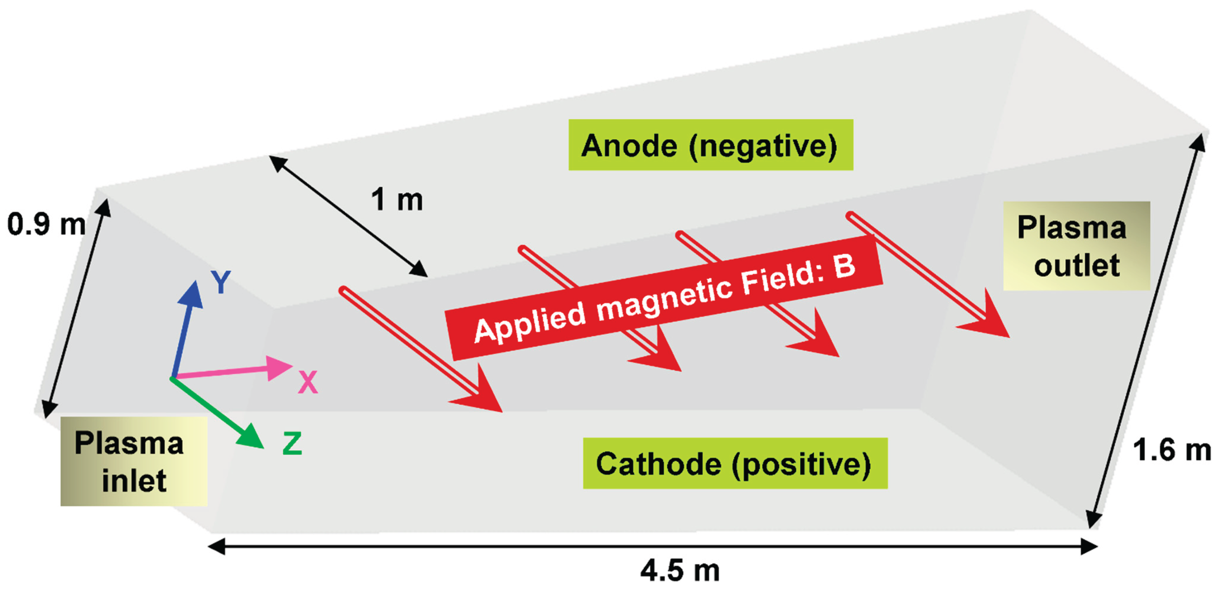
FIGURE 2.
Projection views of the modeled Sakhalin MHD channel
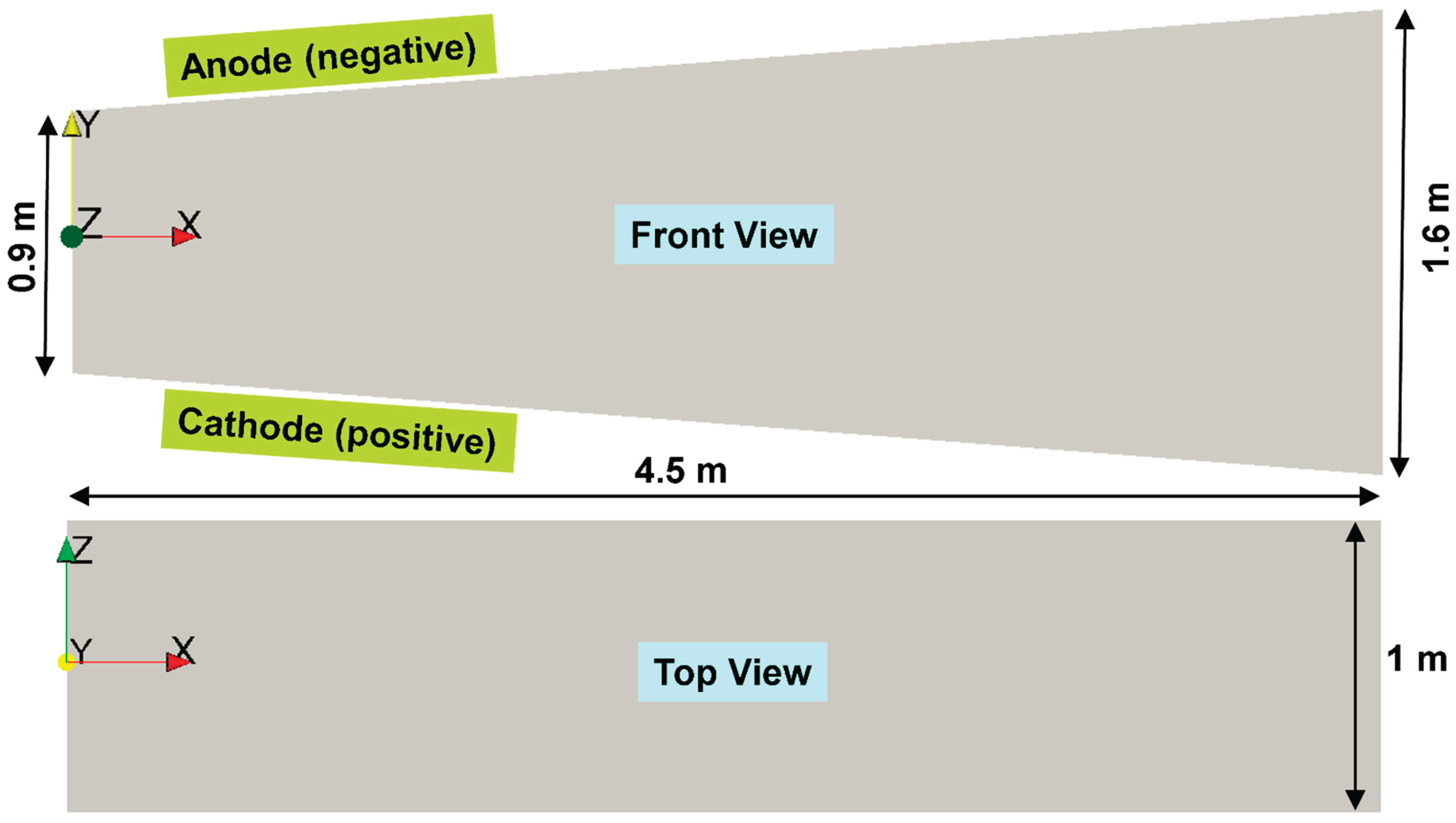
FIGURE 3.
Zoomed views of the discretization mesh of the Sakhalin MHD channel
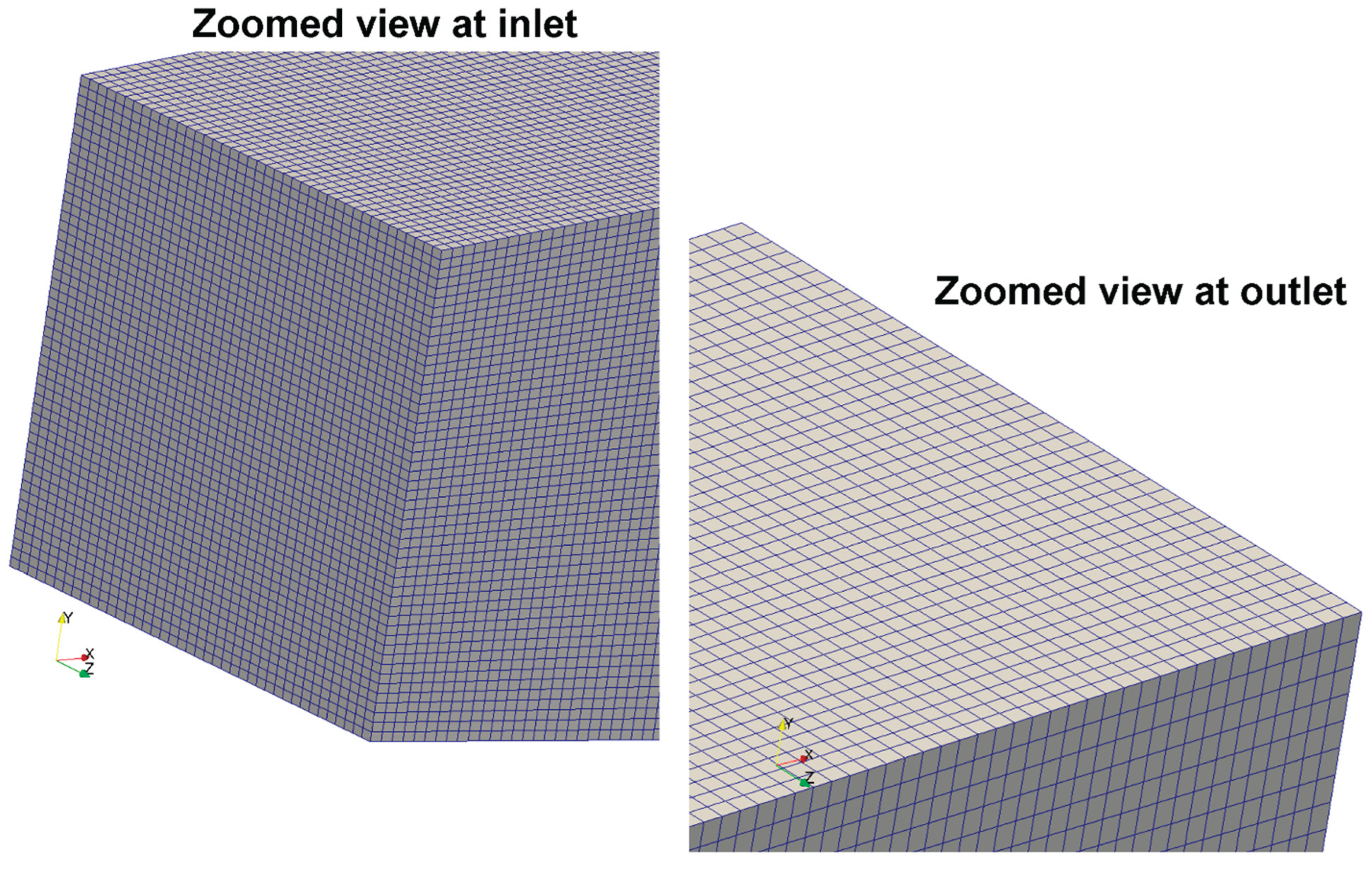
FIGURE 4.
Nonlinear polynomial fitting (seventh-degree polynomial) for the magnitude of the magnetic-field flux density () of the Sakhalin MHD channel, as a function of the axial distance (). The unidirectional magnetic field is in thedirection, and is expressed in teslas ().
FIGURE 4.
Nonlinear polynomial fitting (seventh-degree polynomial) for the magnitude of the magnetic-field flux density () of the Sakhalin MHD channel, as a function of the axial distance (). The unidirectional magnetic field is in thedirection, and is expressed in teslas ().
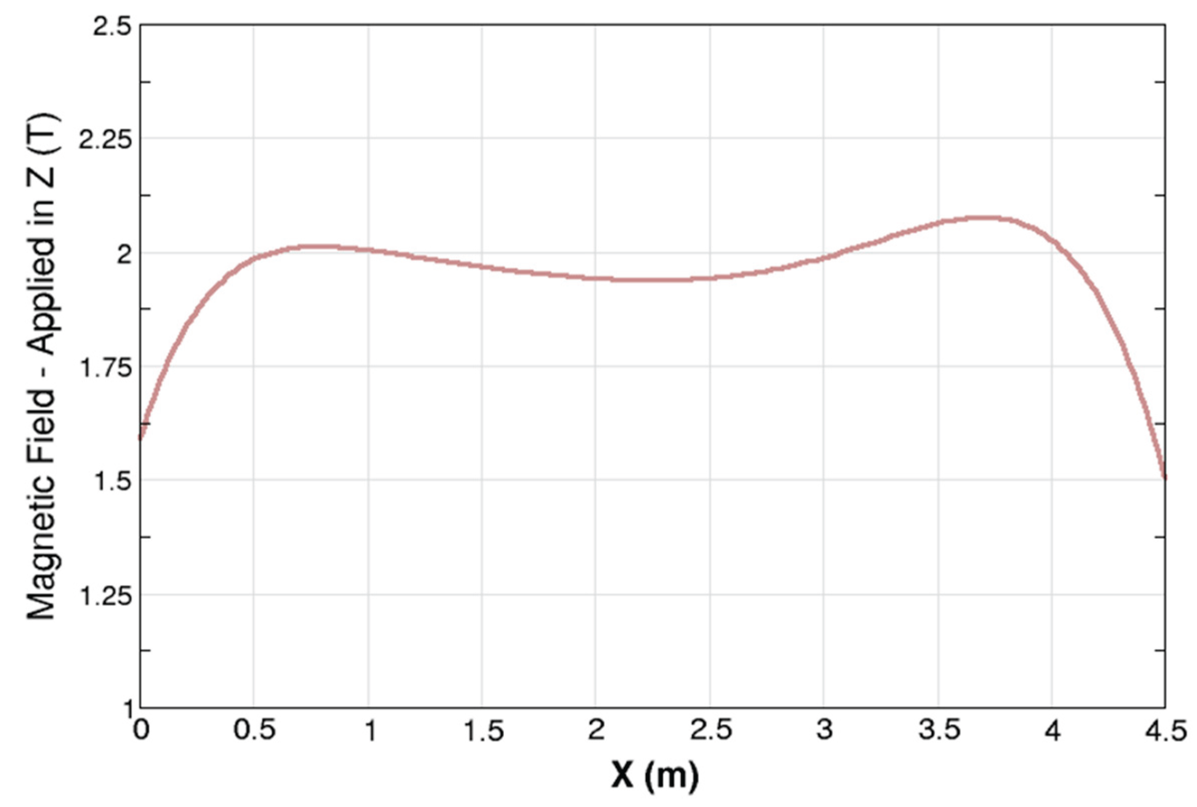
FIGURE 5.
Centerline profile of the electric conductivity along the simulated Sakhalin MHD channel.
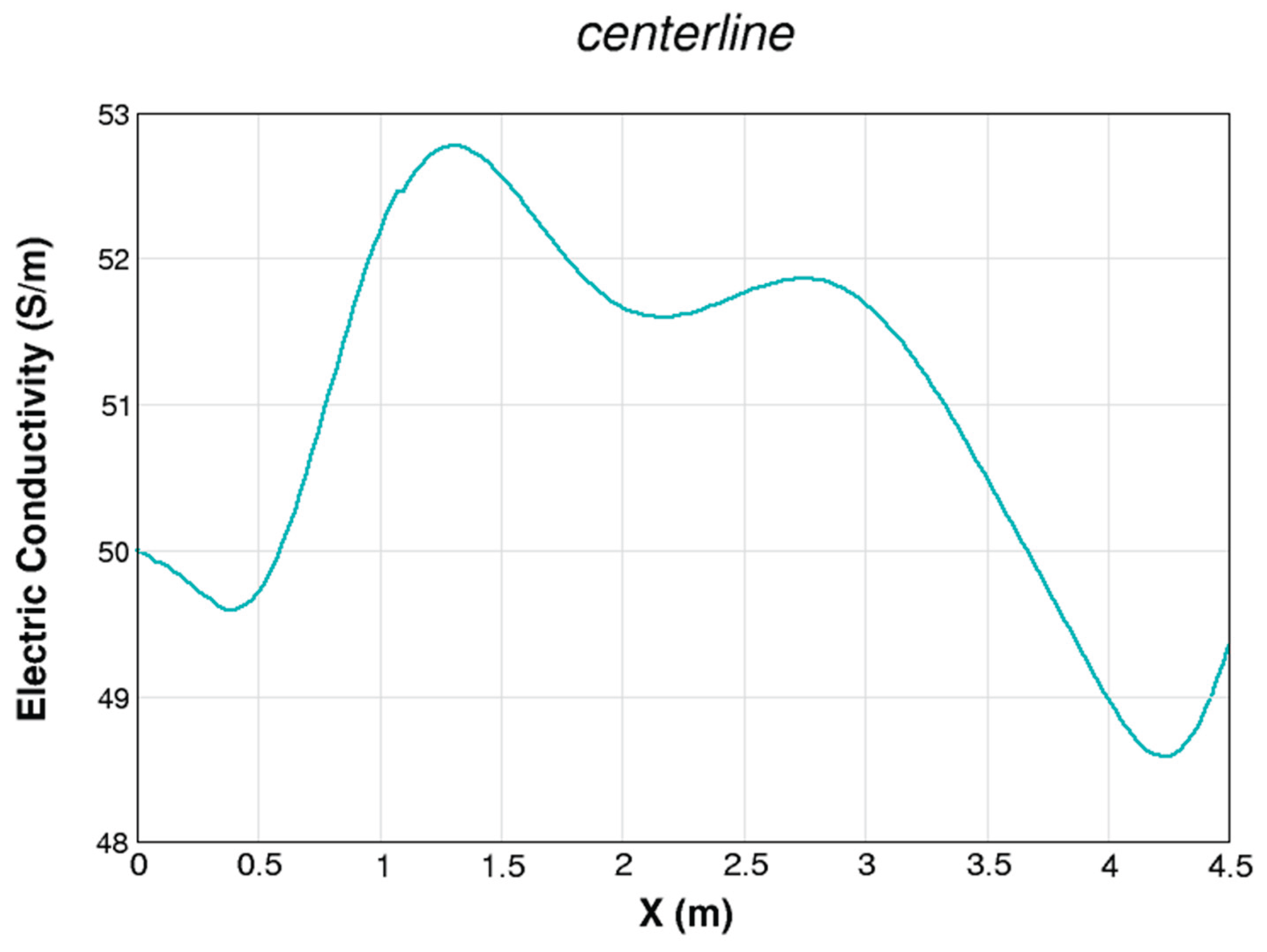
FIGURE 6.
Centerline profile of the Hall parameter along the simulated Sakhalin MHD channel.
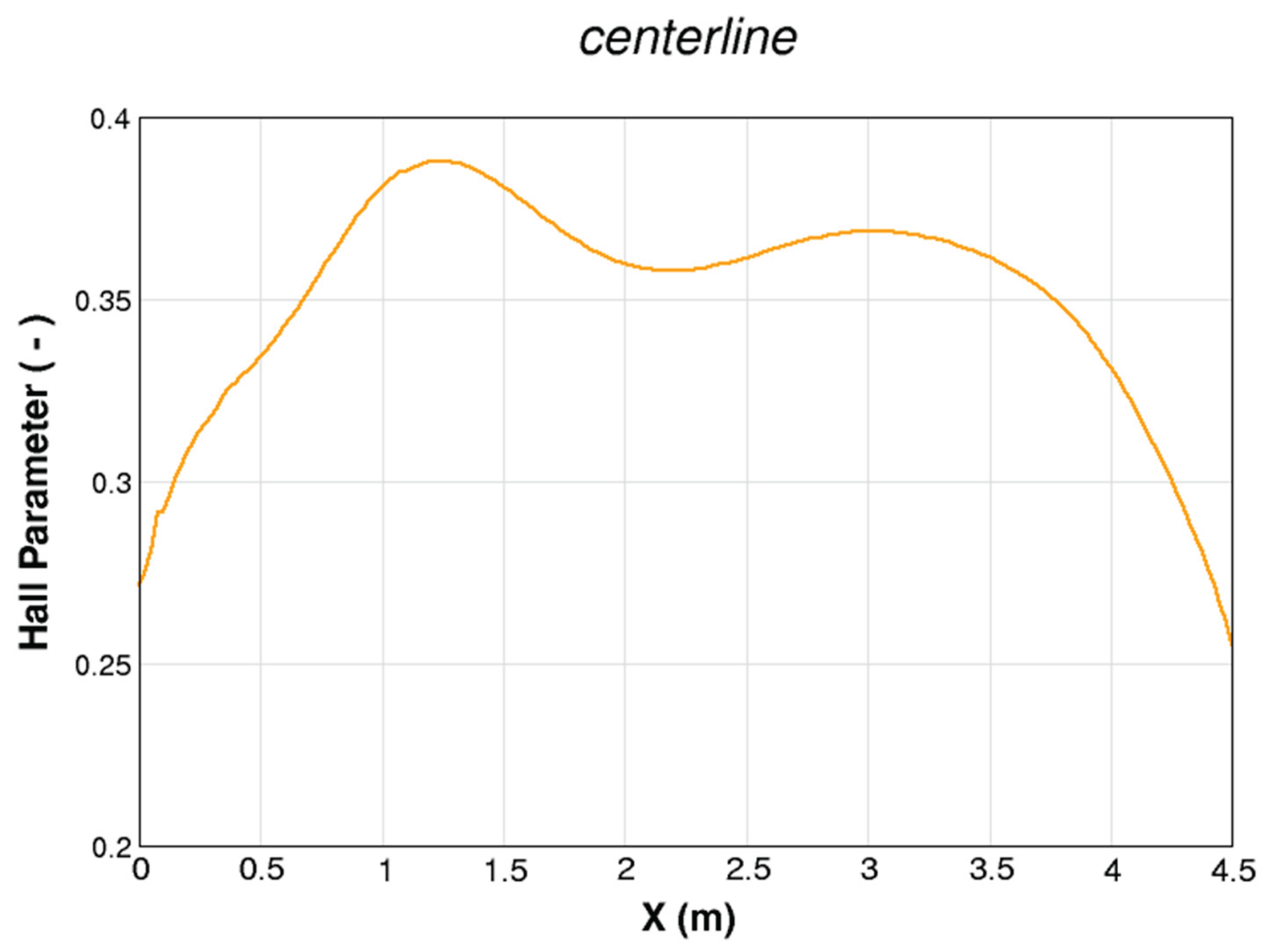
FIGURE 7.
Centerline profile of the Mach number along the simulated Sakhalin MHD channel.
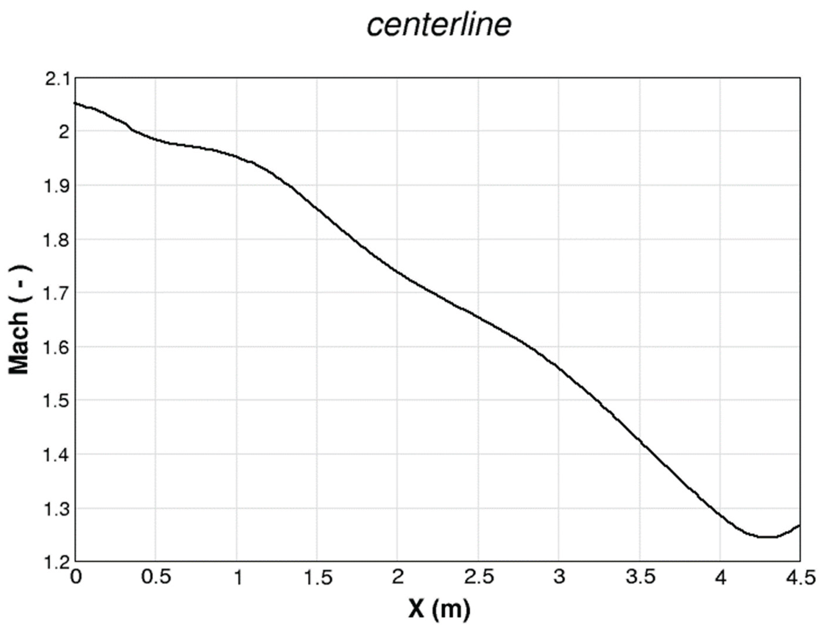
FIGURE 8.
Centerline profile of the absolute pressure along the simulated Sakhalin MHD channel.
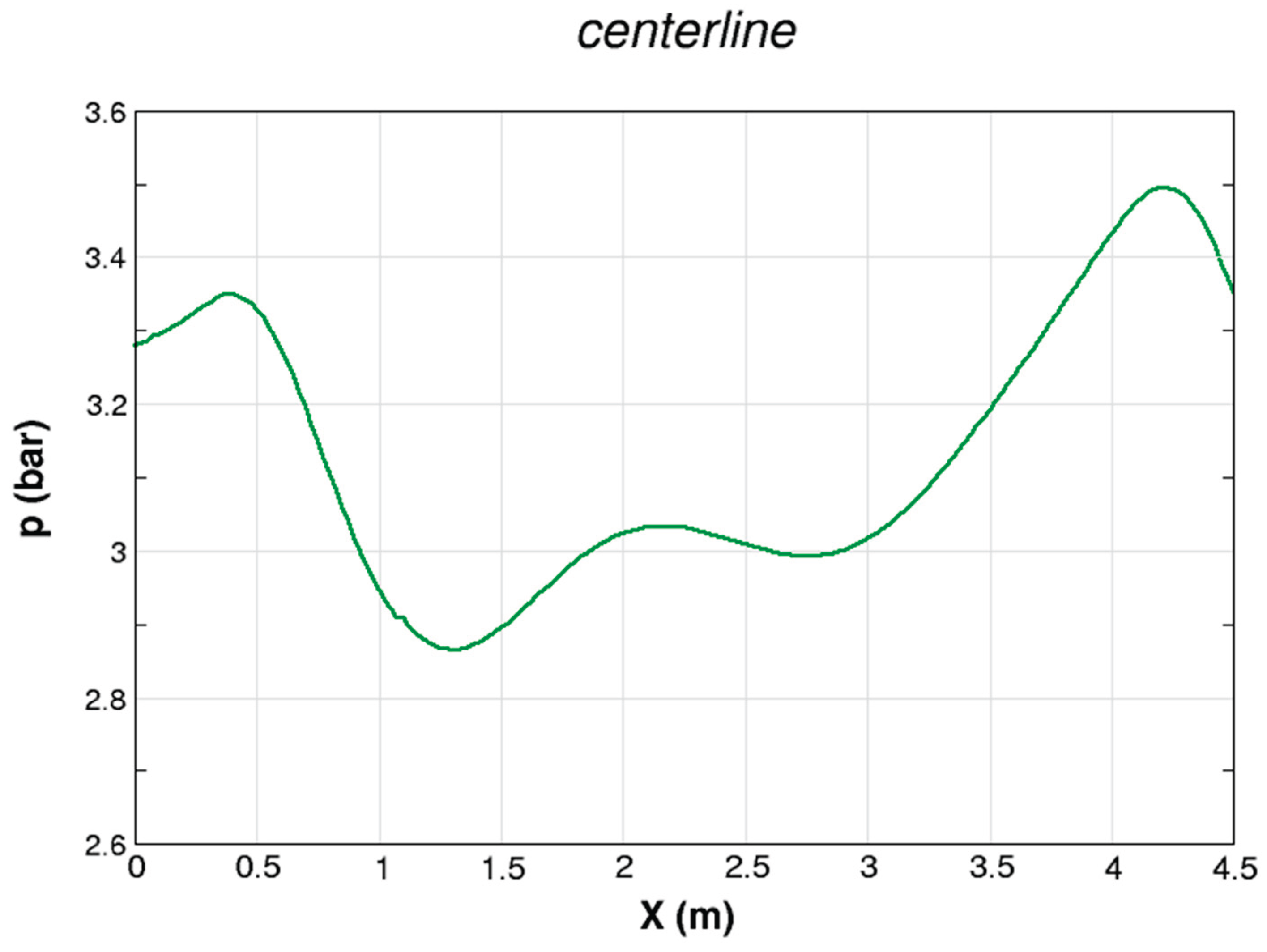
FIGURE 9.
Centerline profile of the plasma density along the simulated Sakhalin MHD channel.
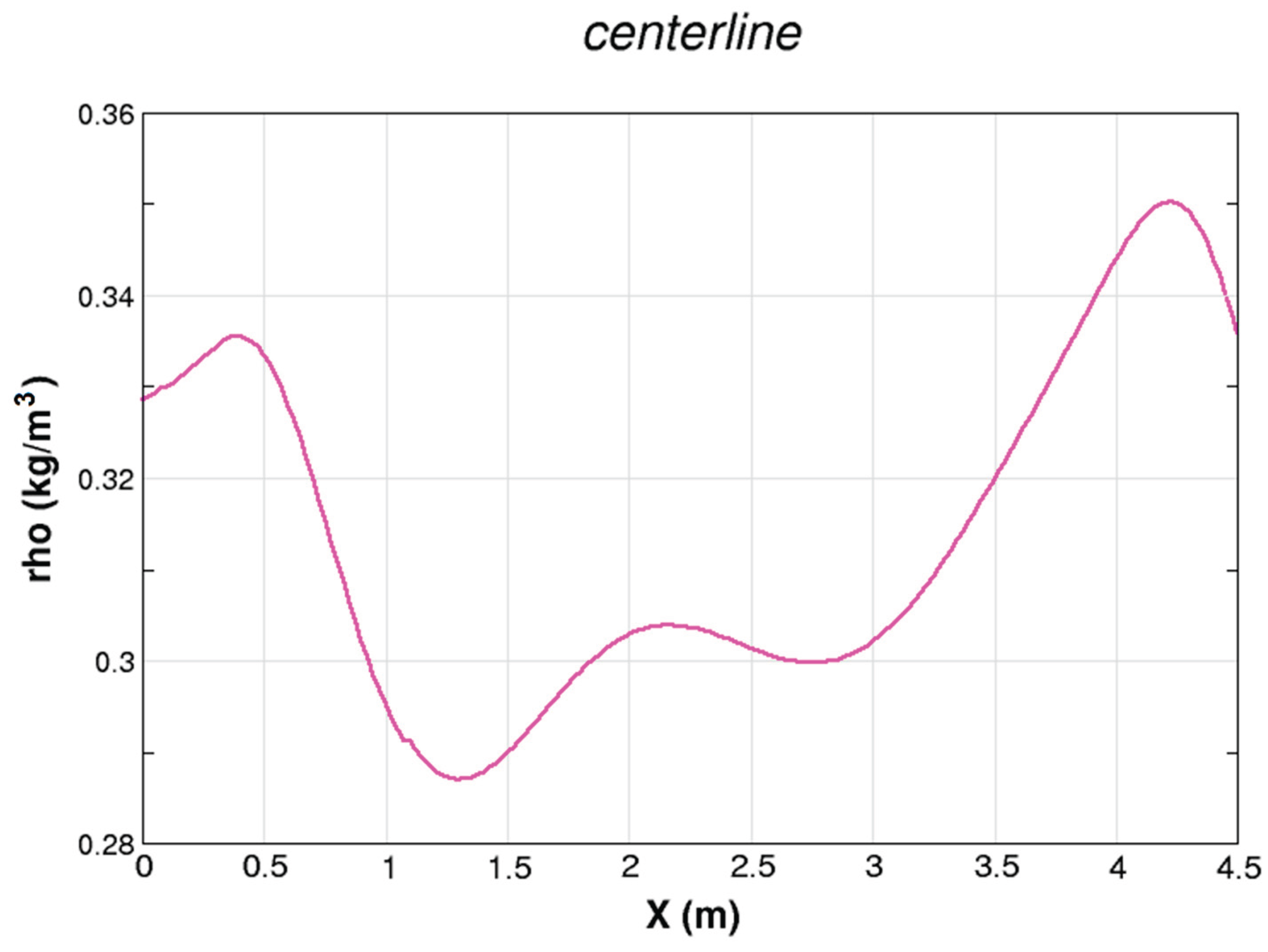
FIGURE 10.
Centerline profile of the absolute temperature along the simulated Sakhalin MHD channel.
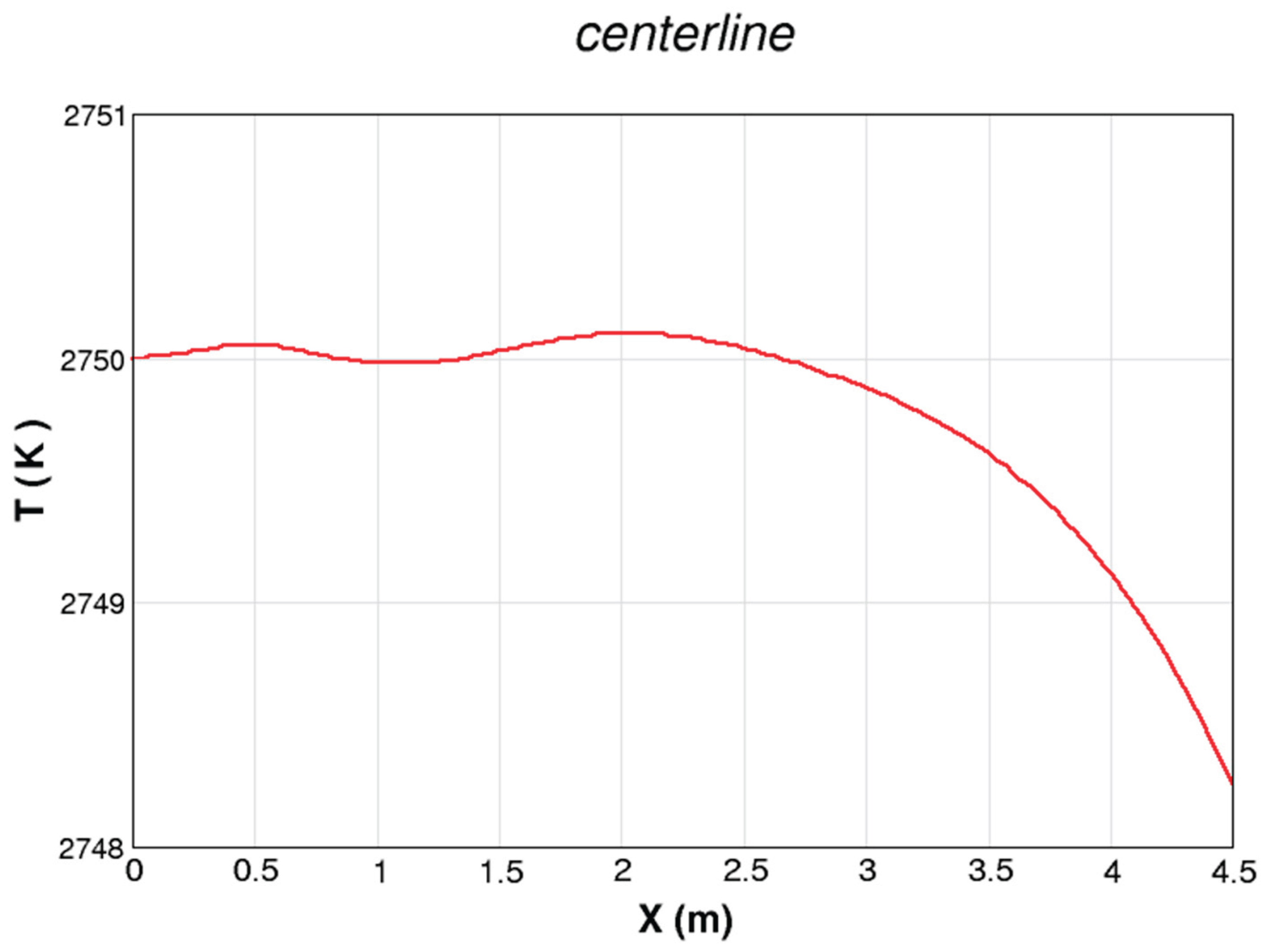
FIGURE 11.
Centerline profile of the axial velocity component along the simulated Sakhalin MHD channel.
FIGURE 11.
Centerline profile of the axial velocity component along the simulated Sakhalin MHD channel.
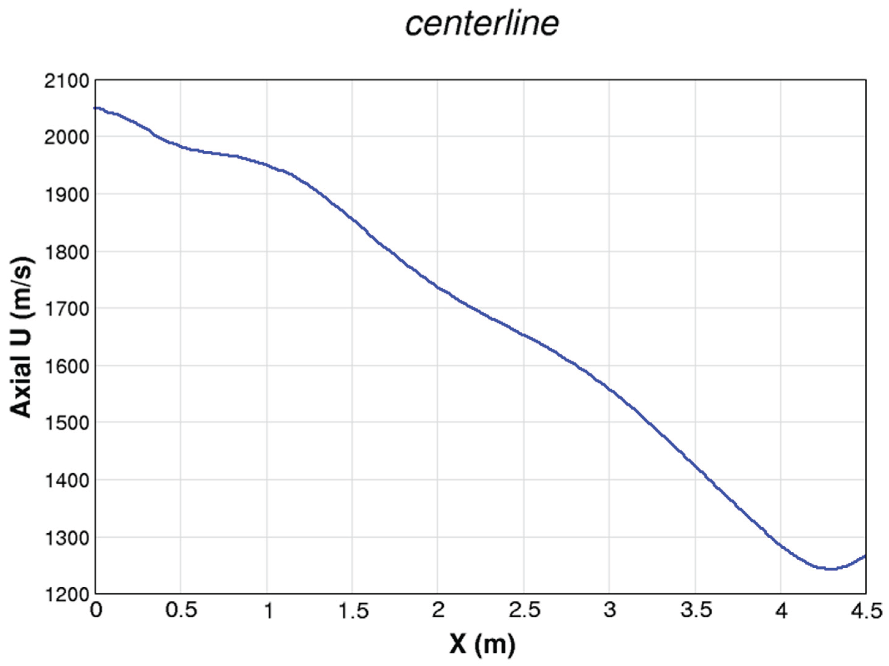
FIGURE 12.
Centerline profile of the upward velocity component (the-compoent) along the simulated Sakhalin MHD channel.
FIGURE 12.
Centerline profile of the upward velocity component (the-compoent) along the simulated Sakhalin MHD channel.
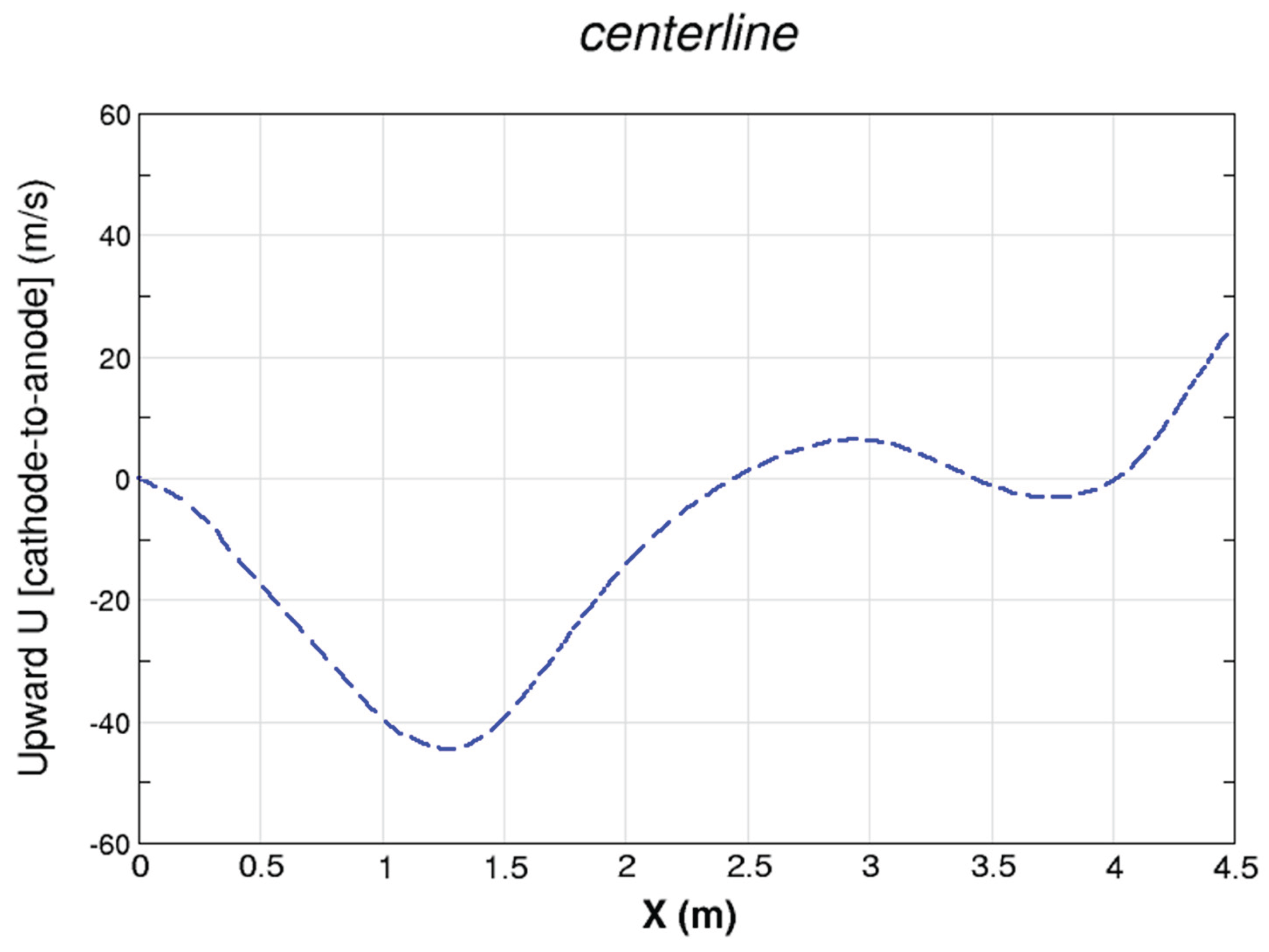
FIGURE 13.
Centerline profile of the lateral velocity component (the-compoent) along the simulated Sakhalin MHD channel.
FIGURE 13.
Centerline profile of the lateral velocity component (the-compoent) along the simulated Sakhalin MHD channel.
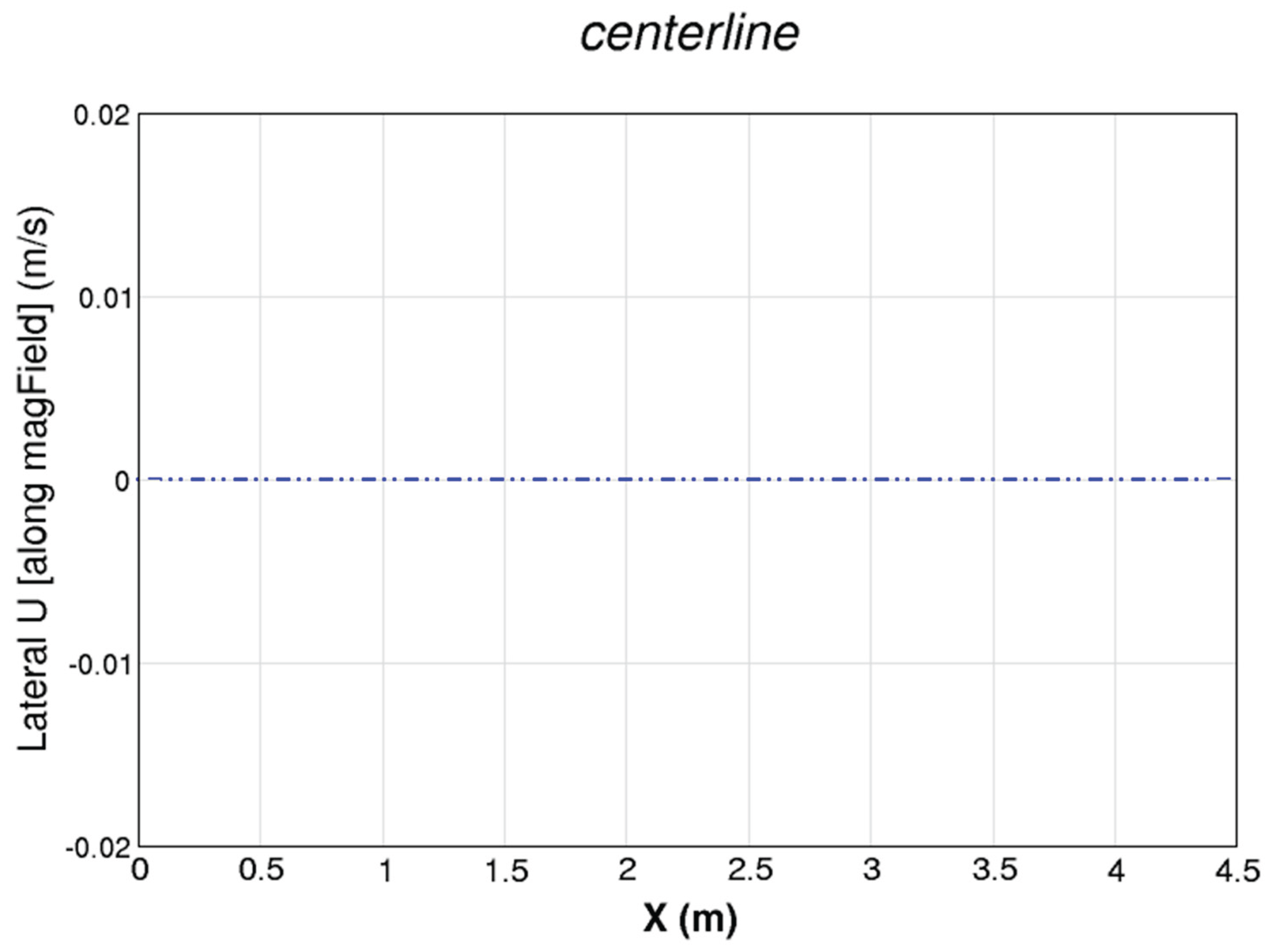
FIGURE 14.
Centerline profile of the downward component of the electric-current density (from anode to cathode) along the simulated Sakhalin MHD channel.
FIGURE 14.
Centerline profile of the downward component of the electric-current density (from anode to cathode) along the simulated Sakhalin MHD channel.
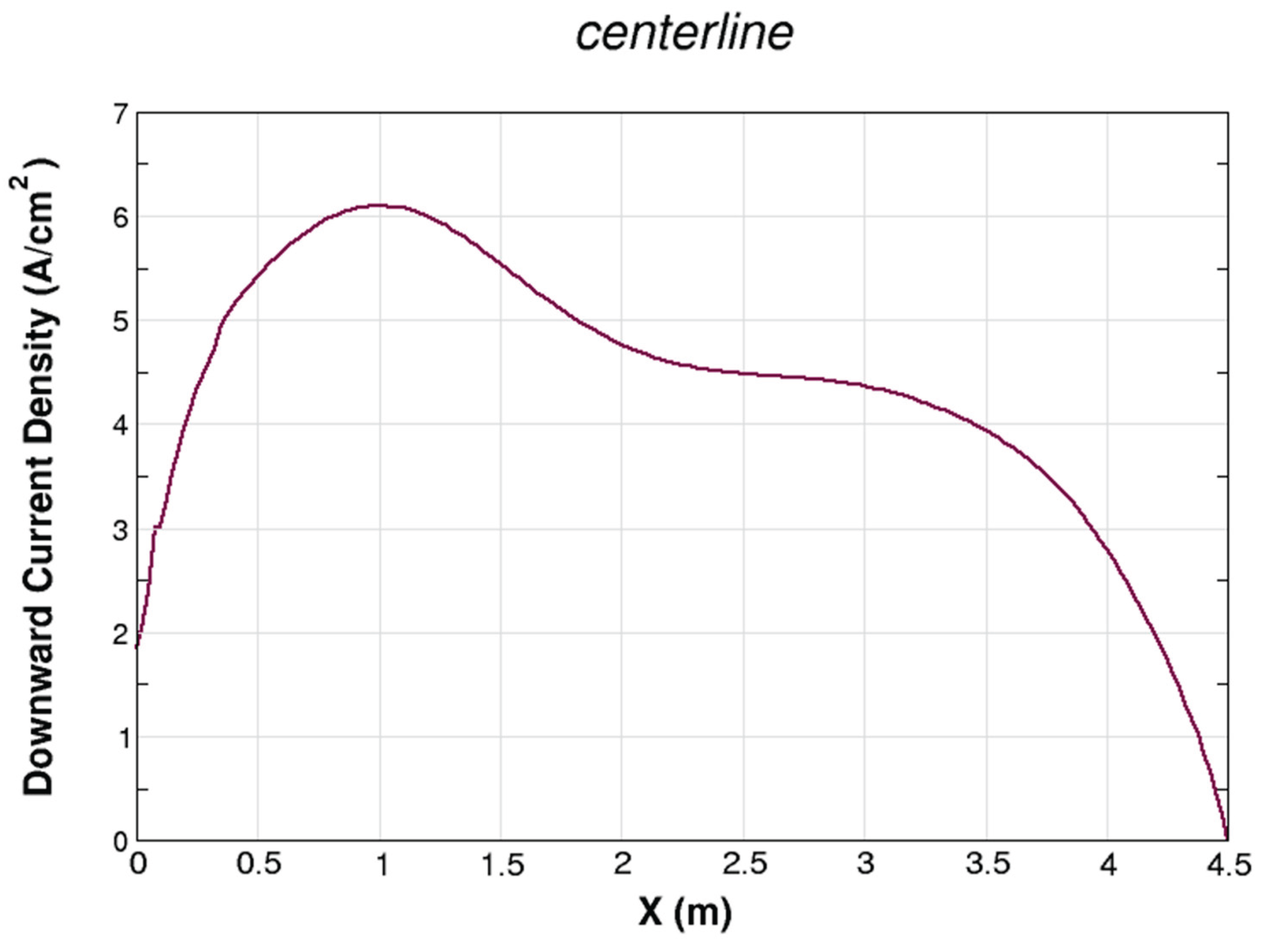
FIGURE 15.
Three-dimensional distribution of the electric conductivity within the simulated Sakhalin MHD channel.
FIGURE 15.
Three-dimensional distribution of the electric conductivity within the simulated Sakhalin MHD channel.
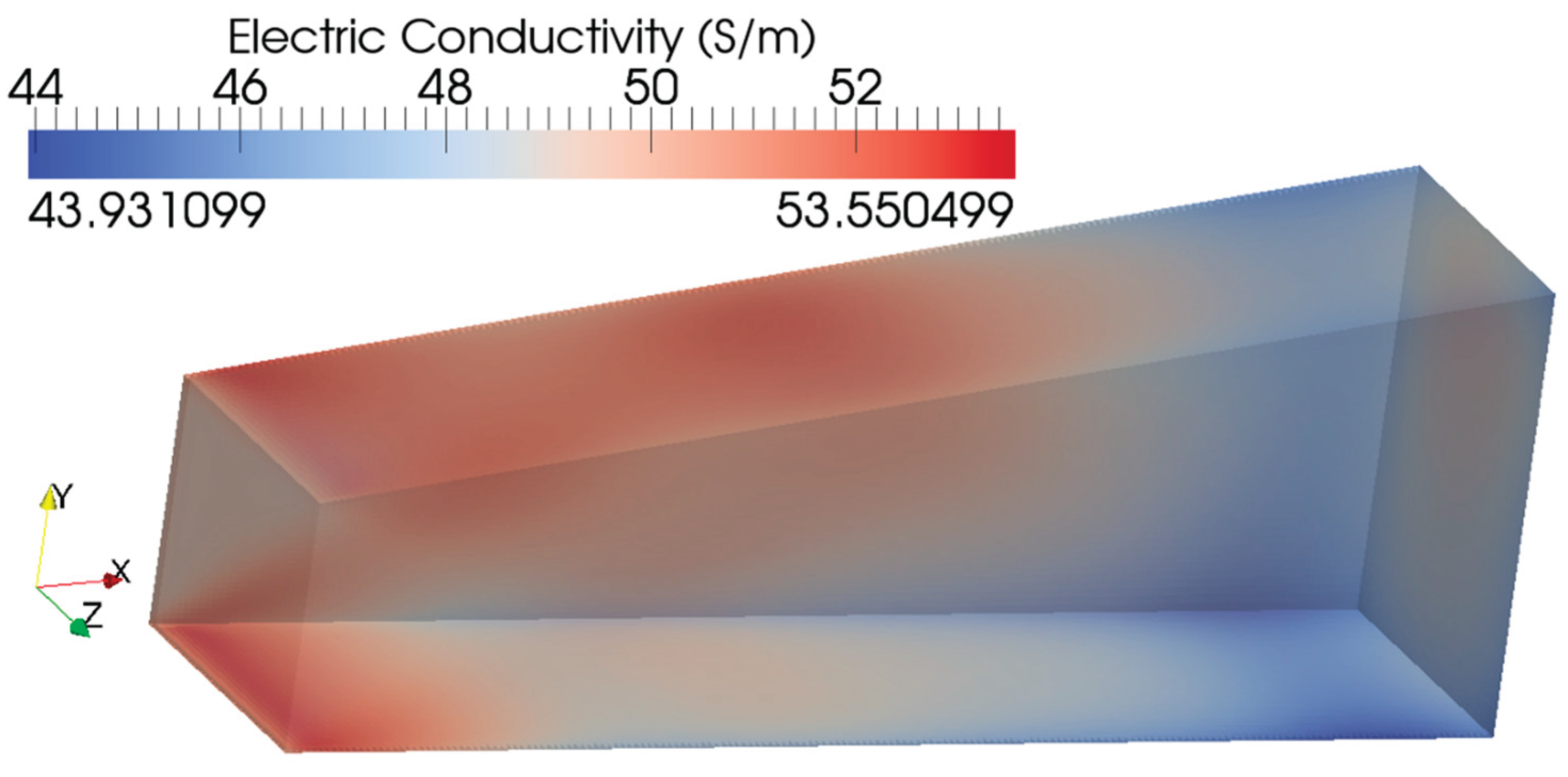
FIGURE 16.
Three-dimensional distribution of the Hall parameter conductivity within the simulated Sakhalin MHD channel.
FIGURE 16.
Three-dimensional distribution of the Hall parameter conductivity within the simulated Sakhalin MHD channel.
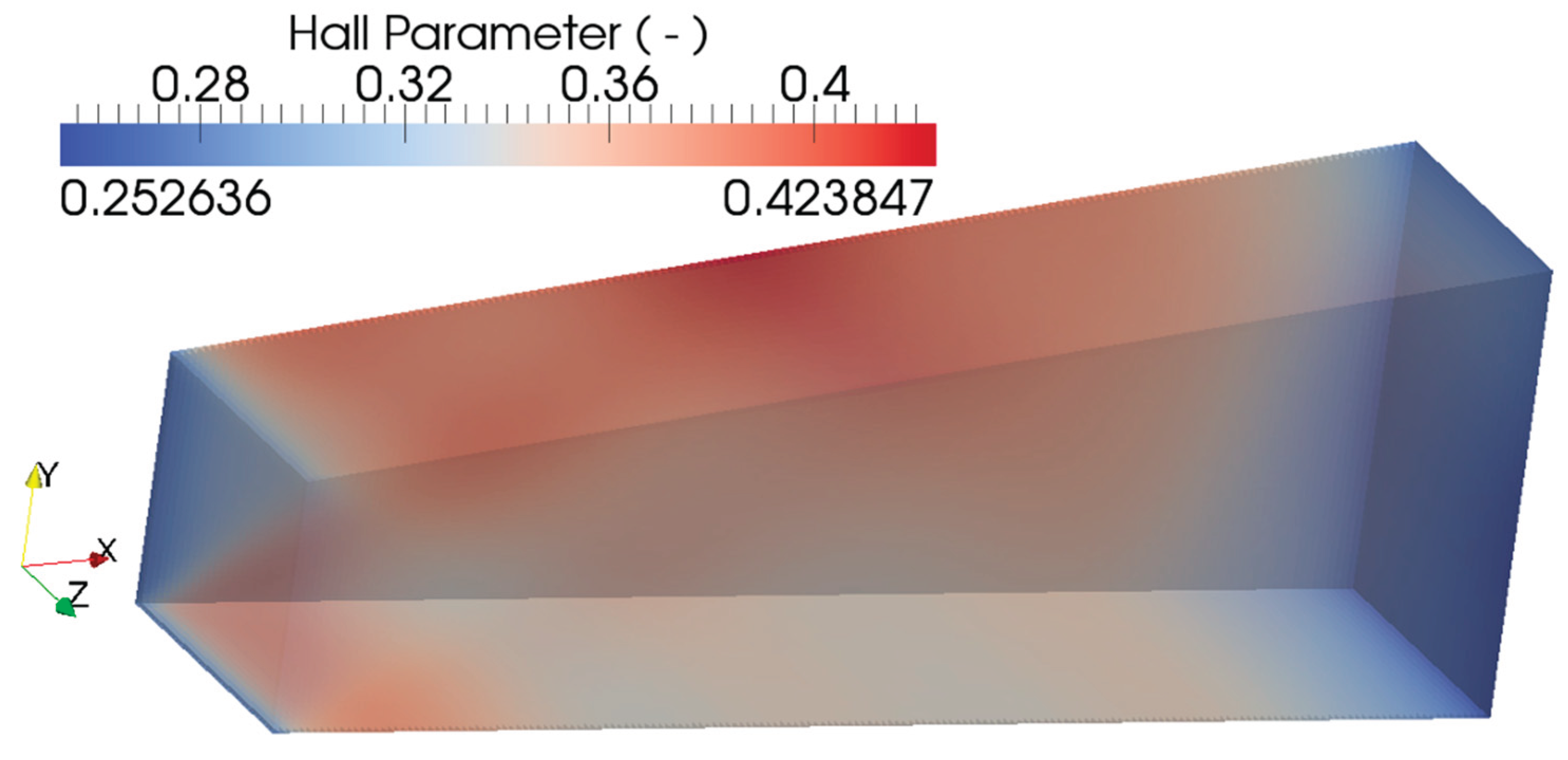
FIGURE 17.
Three-dimensional distribution of the absolute pressure within the simulated Sakhalin MHD channel.
FIGURE 17.
Three-dimensional distribution of the absolute pressure within the simulated Sakhalin MHD channel.
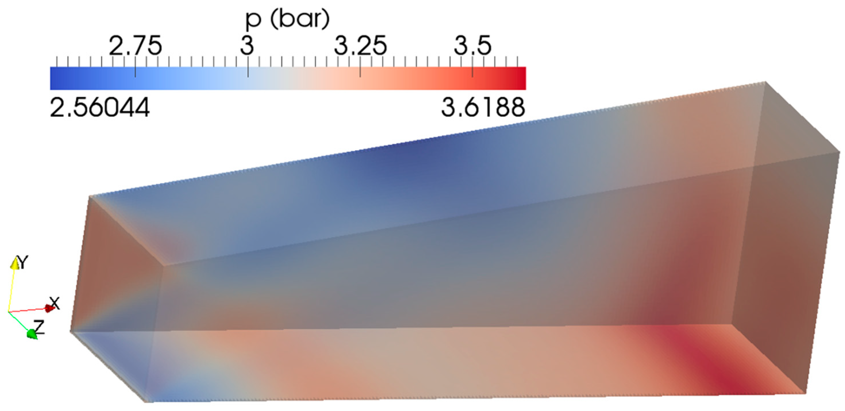
FIGURE 18.
Three-dimensional distribution of the axial velocity component within the simulated Sakhalin MHD channel.
FIGURE 18.
Three-dimensional distribution of the axial velocity component within the simulated Sakhalin MHD channel.
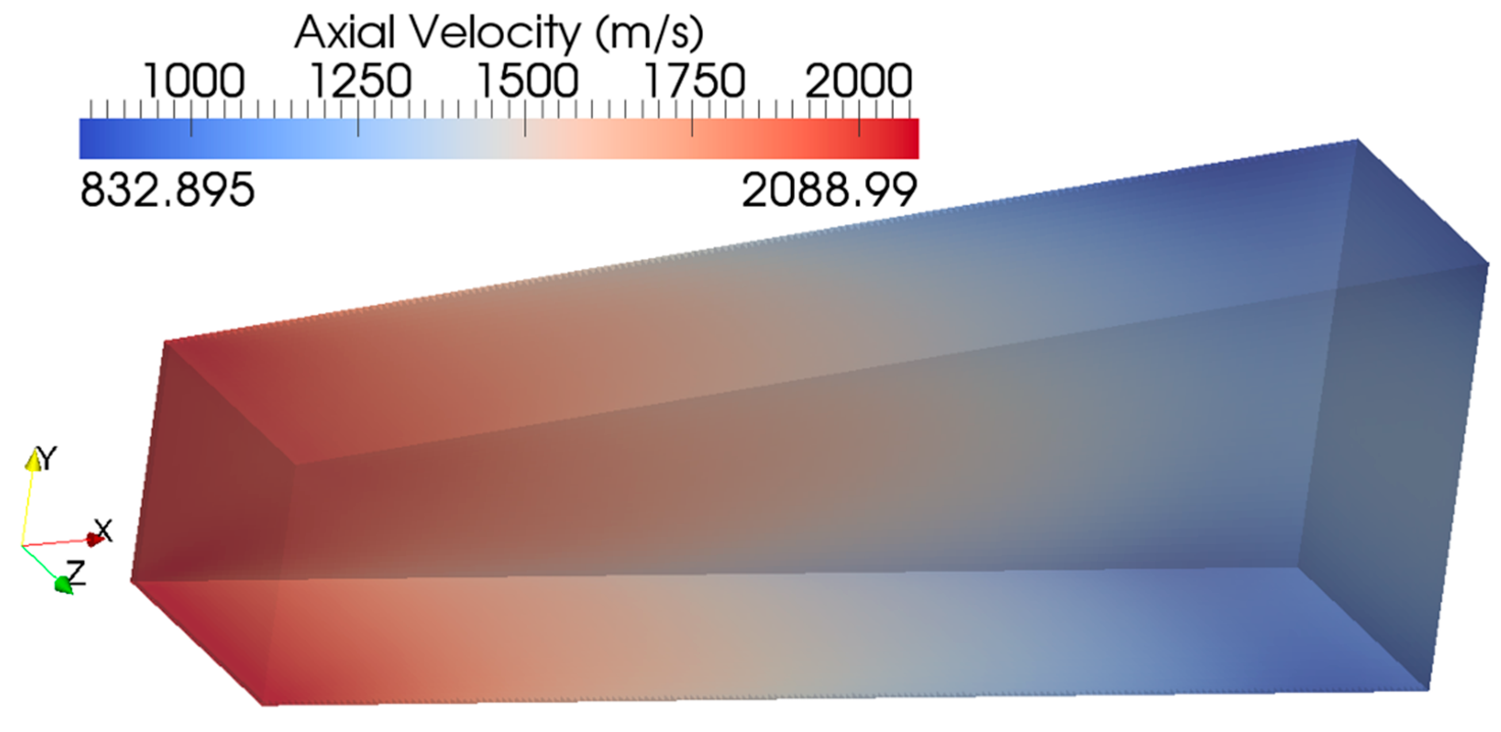
FIGURE 19.
Three-dimensional distribution of the specific (per unit mass) turbulent kinetic energy within the simulated Sakhalin MHD channel.
FIGURE 19.
Three-dimensional distribution of the specific (per unit mass) turbulent kinetic energy within the simulated Sakhalin MHD channel.
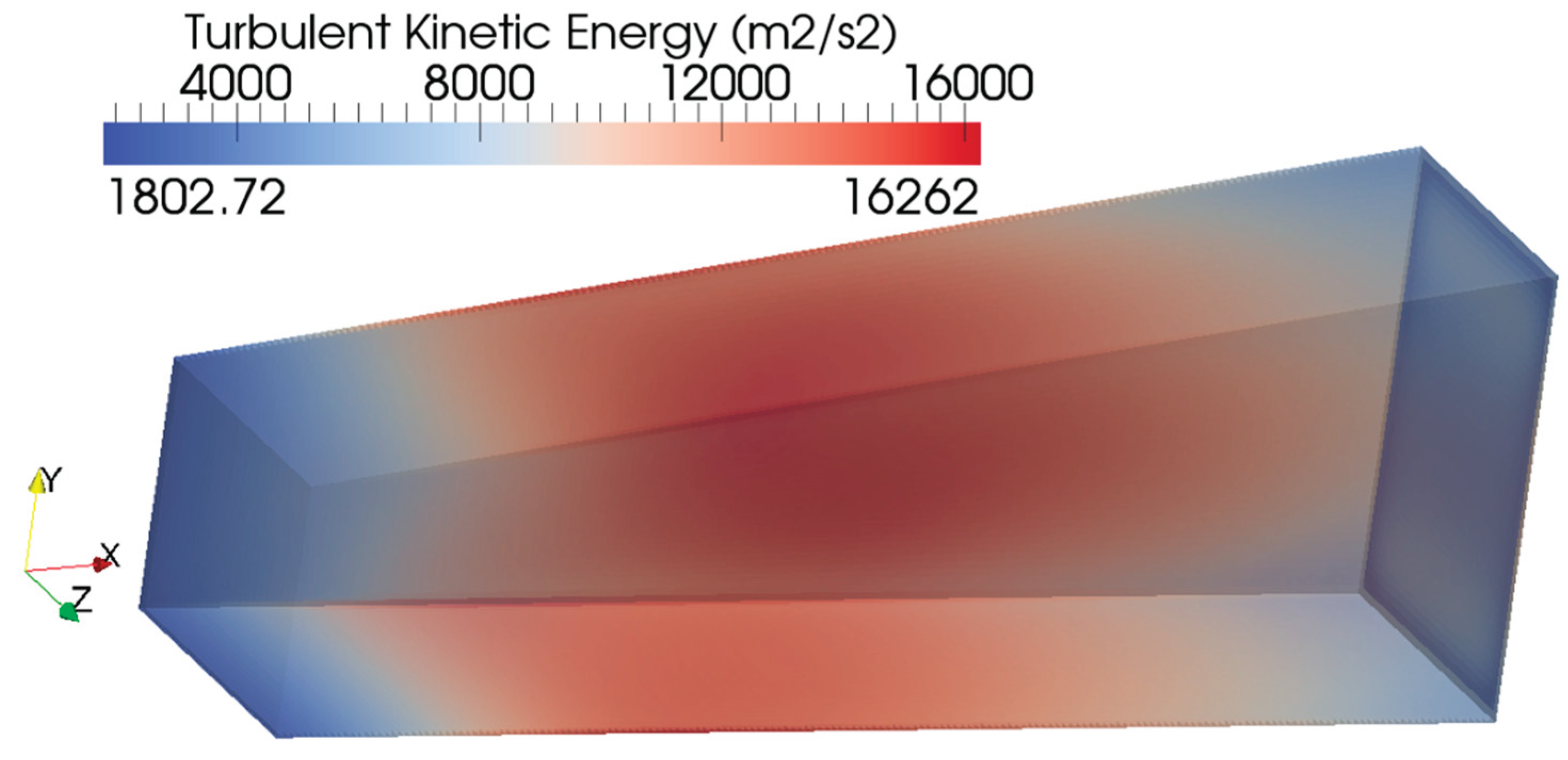
FIGURE 20.
Three-dimensional distribution of the dissipation (epsilon) of the turbulent kinetic energy within the simulated Sakhalin MHD channel.
FIGURE 20.
Three-dimensional distribution of the dissipation (epsilon) of the turbulent kinetic energy within the simulated Sakhalin MHD channel.
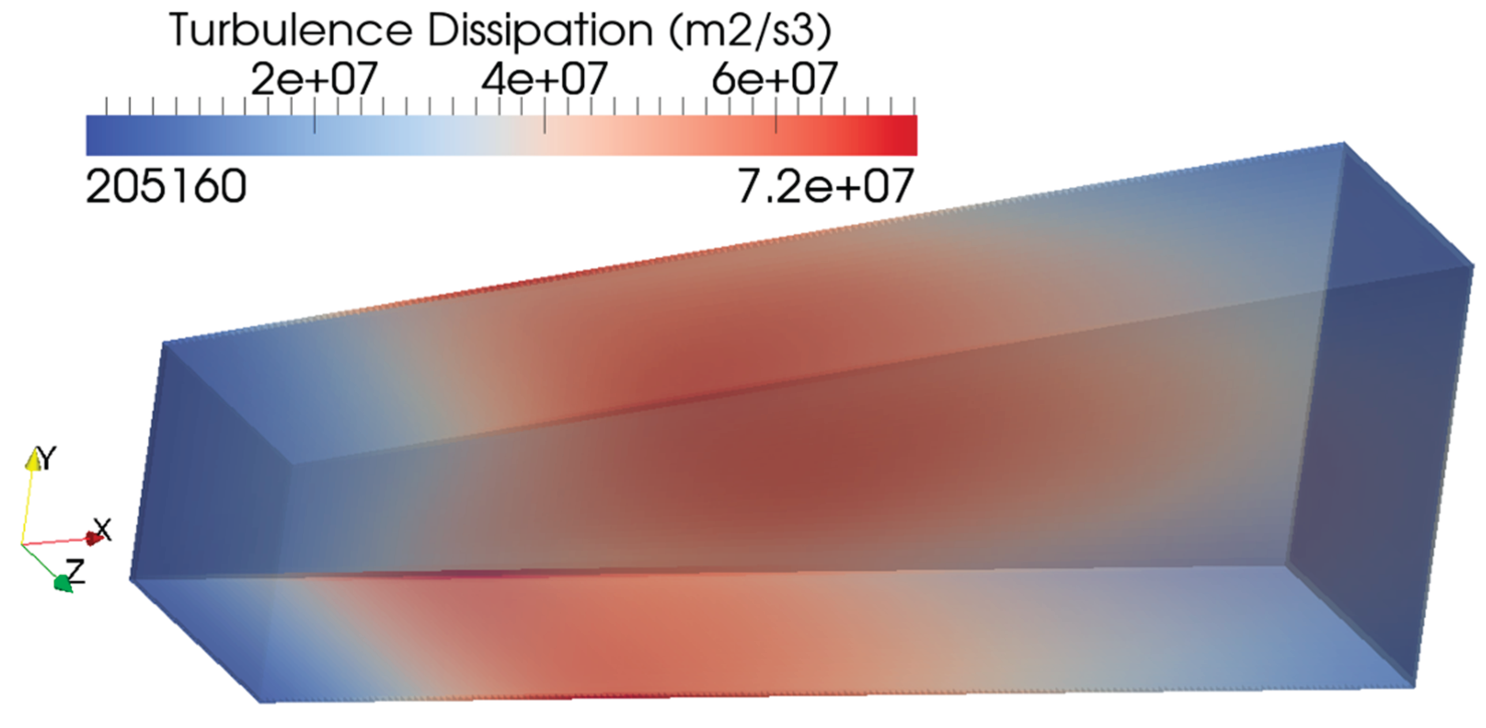
FIGURE 21.
Three-dimensional distribution of the axial component of the electric-current within the simulated Sakhalin MHD channel.
FIGURE 21.
Three-dimensional distribution of the axial component of the electric-current within the simulated Sakhalin MHD channel.
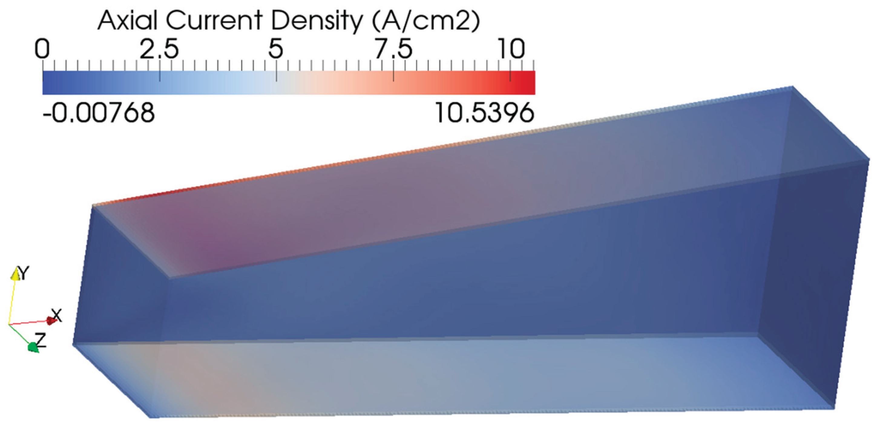
FIGURE 22.
Three-dimensional distribution of the downward component of the electric-current density within simulated Sakhalin MHD channel.
FIGURE 22.
Three-dimensional distribution of the downward component of the electric-current density within simulated Sakhalin MHD channel.
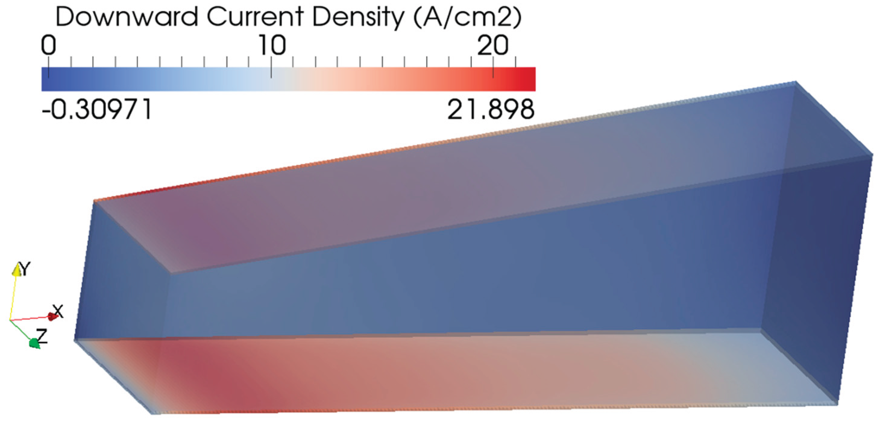

TABLE I.
COMPARISON OF DIFFERENT SOLID-PROPELLANT PLASMA (SPP) SELF-CONTAINED PULSED MAGNETOHYDRODYNAMIC GENERATORS (PMHDG) IN THE FORMER UNION OF SOVIET SOCIALIST REPUBLICS (USSR). AN EMPTY CELL HAVING A DASH SYMBOL (-) INDICATES AN UNKNOWN VALUE FOR US.
TABLE I.
COMPARISON OF DIFFERENT SOLID-PROPELLANT PLASMA (SPP) SELF-CONTAINED PULSED MAGNETOHYDRODYNAMIC GENERATORS (PMHDG) IN THE FORMER UNION OF SOVIET SOCIALIST REPUBLICS (USSR). AN EMPTY CELL HAVING A DASH SYMBOL (-) INDICATES AN UNKNOWN VALUE FOR US.
| Power System (Ordered by Power) | Pamir-0-KT | Pamir-1 | Pricaspiy | Pamir 3U | Soyuz | Ural | Khybiny | Sakhalin |
| Maximum electric power demonstrated (with an unmatched load), MW | 0.1 | 20 | 20 | 30 | 31 | 40 | 120 | 500 |
| Maximum electric power demonstrated (with a matched load), MW | - | 10 | 10 | 15 | 16 | 30 | 60 | 400 |
| Mobility | - | In containers | Mobile on a track | In containers | Mobile on a trailer | - | In containers | In containers |
| Number of MHD channels | 1 | 2 | 2 | 3 | 1 | 1 | 2 | 1 |
| Length of MHD channel(s), m | 1 | 1 | 1 | 1 | 1.8 | - | 1.17 | 4.5 |
| Operating duration for the load (duration of the pulse), s | Up to 3.6 | 3-7 | 3-7 | 2.5-10 | Up to 10 | 6 | 7-10 | Up to 7 |
| Minimum pause between two runs, h | - | 12 | 12 | - | 12 | - | 12 | 24 |
| Approximate maximum possible mass flow rate of working fluid (plasma), kg/s | 2 | 50 | 50 | 24 | 40 | 100 | 200 | 1,000 |
| Overall mass of the power system, tonne | - | 8 | 12 | 18 | 25 | 16 | 34 | 50 |
| Overall dimensions of the power system, m | - | 4 × 1.5 × 2 | 4 × 1.5 × 2 | - | 7 × 2 × 2 | - | 8 × 7 × 1.5 | 13.5 × 3.7 × 2.7 |
TABLE II.
EMPIRICAL EXPRESSIONS AND OPERATING CONDITIONS FOR SAKHALIN PLASMA
| Quantity | Unit | Expression or Value | Remarks |
| Specific heat capacity at constant pressure, | J/(kg.K) |
|
|
| Magnetic-field flux density magnitude, | T (tesla) |
|
|
| Hall parameter, | - |
|
|
| Scalar electric conductivity, | S/m (siemens per meter) |
|
|
| Cathode voltage, | V (volt) | 2,550 |
|
| Plasma molecular weight, | kg/kmol | 22.905 |
|
| Plasma specific gas constant, | J/(kg.K) | 362.978 | |
| Inlet temperature, | K (kelvin) | 2,750 |
|
| Inlet pressure, | bar | 3.28 |
|
| Inlet axial velocity, | m/s | 2,050 |
|
| Inlet specific heat capacity at constant pressure, | J/(kg.K) | 2,357.426 | |
| Inlet specific heat capacity at constant volume, | J/(kg.K) | 1,994.448 |
|
| Inlet specific heat ratio, | - | 1.1820 |
|
| Inlet speed of sound, | m/s | 999.5 |
|
| Inlet Mach number, | - | 2.05 |
|
| Inlet Plasma density, | kg/m3 | 0.32859 | |
| Inlet cross-section area, | m2 | 0.9 |
|
| Mass flow rate, | kg/s | 606.2 |
|
| Outlet cross-section area, | m2 | 1.6 |
|
a This speed of sound corresponds to a temperature of = 2,328 K. If the centerline plasma temperature of = 2,750 K is used, the formula gives 1,086.2 m/s. The temperature at the inlet can be viewed as a combined effect of the hotter core plasma and the colder walls and near-wall region, or as the temperature of the plasma at the centerline, which has the highest temperature in the inlet boundary.
TABLE III.
SOME SIMULATION CONDITIONS FOR THE CFD SIMULATION OF THE SAKHALIN MHD CHANNEL
| Condition | Adopted Setting |
| Turbulence model | Standard k-epsilon 247,248,247 |
| Flow solver | Density-based, nearly explicit |
| Upwind scheme | Kurganov central 249–252 |
| Prandtl number (Pr) | 0.72 253,254 |
| Time-step | 5 × 10⁻⁶ s (5 μs) |
| Completed time steps | 8000 |
| Simulated time | 0.04 s |
TABLE IV.
VALIDATION OF OUR SIMULATION FOR THE SAKHALIN MHD CHANNEL
| Quantity | Our Value | Benchmarking Value | Remarks |
| Electric power output | 488.1 MW | 476 MW 261 |
|
| Electric current from electrodes | 191.4 kA | 200 kA 263 |
|
| Plasma speed at channel exit | 1,156 m/s | 1,306 m/s 264 |
|
TABLE V.
VERIFICATION OF OUR SIMULATION FOR THE SAKHALIN MHD CHANNEL (RESOLUTION SENSITIVITY ANALYSIS)
TABLE V.
VERIFICATION OF OUR SIMULATION FOR THE SAKHALIN MHD CHANNEL (RESOLUTION SENSITIVITY ANALYSIS)
| Quantity | Nominal Resolution | Finer Resolution |
| Number of cells | 376,380 | 1,235,250 |
| Time step | 5 × 10⁻⁶ s | 2.5 × 10⁻⁶ s |
| Electric power output | 488.1 MW | 480.3 MW |
| Volume-average pressure | 3.128 bar | 3.011 bar |
| Volume-average Lorentz force density vector | [–89.12, 28.83, 0] kN/m3 | [–85.86, 28.75, 0] kN/m3 |
| Volume-average electric-current density vector | [1.462, –4.517, 0] A/cm2 | [1.457, –4.351, 0] A/cm2 |
TABLE VI.
COMPUTED PROPERTIES OF THE PLASMA (MASS-AVERAGED) AT THE CHANNEL OUTLET, AND CORRESPONDING INLET VALUES
TABLE VI.
COMPUTED PROPERTIES OF THE PLASMA (MASS-AVERAGED) AT THE CHANNEL OUTLET, AND CORRESPONDING INLET VALUES
| Quantity | Outlet Value | Inlet Value |
| Temperature (K) | 2,738.4 | 2,750 |
| Pressure (bar) | 3.294 | 3.28 |
| Axial velocity (m/s) | 1,156 | 2,050 |
| Mach number ( - ) | 1.161 | 2.051 |
| Electric conductivity (S/m) | 48.4 | 50 |
| Hall parameter ( - ) | 0.2555 | 0.2715 |
Disclaimer/Publisher’s Note: The statements, opinions and data contained in all publications are solely those of the individual author(s) and contributor(s) and not of MDPI and/or the editor(s). MDPI and/or the editor(s) disclaim responsibility for any injury to people or property resulting from any ideas, methods, instructions or products referred to in the content. |
© 2025 by the authors. Licensee MDPI, Basel, Switzerland. This article is an open access article distributed under the terms and conditions of the Creative Commons Attribution (CC BY) license (http://creativecommons.org/licenses/by/4.0/).
Copyright: This open access article is published under a Creative Commons CC BY 4.0 license, which permit the free download, distribution, and reuse, provided that the author and preprint are cited in any reuse.


