
Submitted:
05 September 2025
Posted:
08 September 2025
You are already at the latest version
Abstract
With the development of drone technology in recent years, many studies have discussed how to leverage drones equipped with sensors and cameras to conduct inspections un-der bridges. To address positioning challenges caused by the lack of GPS signals under the bridges, triangulation methods with on-site pre-installed UWB sensors were used extensively to determine drone locations. However, the practical hurdles of deploying anchors under bridges are often overlooked, including variable terrain and potential electromagnetic interference from deploying a large number of UWB sensors. This study introduces a handover mechanism to address long-distance positioning challenges and an improved two-stage algorithm to enhance its suitability for bridge terrain with higher stability. By integrating these concepts, a practical bridge inspection system was devised, and realistic under-bridge experiments were conducted to validate the method's efficacy in real-world settings.
Keywords:
bridge inspection
; GPS-free
; Handover
; UWB
; wireless positioning
1. Introduction
Bridges are a vital piece of infrastructure critical to people's daily lives, but their components inevitably degrade over time. Without proper maintenance and repairs, the consequences can be severe. For example, a bridge collapse in Tennessee in 2019 [1] had a significant impact on the lives of residents. Therefore, regular inspections are imperative. However, the current practice of bridge inspection still heavily relies on manual visual inspection, resulting in each inspection requiring a lot of manpower and taking a long time. Hence, developing a more efficient and cost-effective inspection method is of paramount importance.
Unmanned Aerial Vehicles (UAVs), also known as drones, have emerged as highly promising tools thanks to their high maneuverability. In recent years, researchers have dedicated significant efforts in developing automatic bridge inspection systems using UAVs [2, 3]. These frameworks allow an inspection path for drones to be preset, enabling the drones to autonomously navigate along a designated route using GNSS (Global Navigation Satellite System). However, some components of a bridge, such as piers, supports, and abutments, are often located underneath the bridge, which may prevent these methods from being successfully implemented in these areas due to unavailable GPS signals. While techniques like SOP (Signals of Opportunity) [4-6] have been used for determining a drone’s position in GPS-denied areas, they are typically deployed in urban environments where multiple signals are readily available, such as LTE, Wi-Fi, and 5G. However, there is currently no work using this technology in bridge inspection scenarios, possibly because the bridge's location cannot receive such diverse signals.
To enable drones to operate in GPS-denied environments, earlier studies proposed adding sensors to drones, such as optical flow sensors [7, 8] or upward two-dimensional (2-D) laser range finders [9], so that the drone can fly under the bridge by measuring the distance between the underside of the bridge and the drone. Nonetheless, this method only allows the drone to fly autonomously vertically; horizontal control still requires a pilot. Subsequent researches attempt to utilize positioning algorithms with auxiliary sensors, such as Inertial Measurement Units (IMUs), visual sensors, ultrasonic sensors, and Ultra-Wideband (UWB) devices, to achieve fully autonomous flight of drones.
Depending on the type of sensors utilized, they can be divided into two categories: onboard sensors within the drone and off-board sensors mounted on the drone. For instance, an Inertial Navigation System (INS) [10] serves as a classical example, utilizing an IMU within the drone itself to measure angular velocity and linear acceleration. These measurements are then integrated to estimate the drone’s position and direction from the starting point [11]. However, INS is susceptible to errors that accumulate over time, leading to severe estimation errors. This positioning method is typically employed only for short periods of time when the GPS signal is unavailable. Although subsequent studies attempt to reduce accumulated errors through the use of DEM (Digital Elevation Maps) [12], building a DEM can be time-consuming, especially for large or high-resolution datasets.
Other researches focus on mounting off-board sensors on UAVs for positioning, such as visual cameras and beacon-based sensors. In vision-based positioning, visual cameras primarily assist UAV positioning. A common approach is using visual odometry (VO) [13], which tracks the position of a monocular camera from an initial local reference frame [14]. However, the camera only provides a 2-D projection of the scene, making it difficult to accurately estimate the drone’s position due to the lack of scale information. To address this limitation, researchers have turned their attention to RGB [15] or stereo cameras [16]. While these cameras can measure depth to achieve more accurate positioning, their accuracy decreases with increasing distance from the target [17, 18]. To solve this problem, the concept of global attitude estimation has emerged, e.g., SLAM system [19-21], which reduces the impact of accumulated errors by establishing an environment map and continuously updating the target attitude corresponding to the map [22]. But it requires substantial memory space and computing power, which makes implementing this approach on bridges challenging.
Beacon-based sensors, such as ultrasonic range sensors and UWB, are also widely used for positioning. When using this method, anchors must first be deployed in the area to be localized. The tag on the drone can then obtain distance information from the anchors and use a localization algorithm to estimate the location. For example, Ali et al. [23] successfully used ultrasonic range sensors to estimate the global position of a drone. However, the effective communication distance of ultrasonic waves is usually only about ten meters, which limits their use on long bridges.
The effective communication distance of UWB is usually larger than that of ultrasonic sensors, about 50-60 meters. It is also used for various indoor or outdoor positioning problems [24-27], but still faces the limitation of short communication range when applied to bridge inspection. Although this problem can be solved by deploying a large number of UWB anchors under the bridge, the increase in the number of anchors will cause electromagnetic interference between them, making it difficult for the tag to identify which anchors sent the message. Recently, a UWB handover system has been proposed to alleviate these problems [28]. It uses a bipartite graph and a greedy algorithm to transform the problem into a vertex coloring problem to solve the challenge caused by the long area and numerous beams and columns under the bridge.
In addition, most previous studies utilizing UWB for positioning lacked consideration of the terrain where the anchors are deployed. These studies typically conducted positioning experiments on flat ground [24-26, 29]. Although Thien et al. [27] placed anchors at different heights, the experimental area remains relatively small, such as within a 6 by 6 meters square, which is not representative of real-world applications like bridge inspection. Although trilateration positioning is a classical problem, previous studies, such as [30, 31], employed the least squares method and the cosine law to determine the solutions. Positioning accuracy, especially regarding height, is highly sensitive to the placement of anchor positions. Chan et al. [25] proposed using the Taylor series algorithm [30] to enhance height accuracy, but it requires relatively more time due to iterations. Other methods utilize an IMU combined with a Kalman filter [27] or a barometer to enhance vertical position accuracy [26]. However, relying on these sensors for an extended duration may lead to accumulated errors. Recently, an improved UWB positioning algorithm was proposed to address these difficulties [32]. The algorithm employed a two-stage singular value decomposition (SVD) to reduce positioning errors caused by tilted anchor configurations. Furthermore, optimal anchor placement strategies were explored to provide better positioning accuracy, enhancing more precise outlier detection and robust performance in bridge inspection environments.
Hence, it is crucial to develop a method that adapts to the terrain under the bridge and allows UAVs to be positioned with high accuracy for long periods of time. This study proposes innovative ideas to address this problem, with major contributions outlined below:
- presents an inspection system tailored to various bridge terrains and conducts practical experiments on real bridge structures.
- applies a handover mechanism to prevent electromagnetic interference among anchors, and ensures accurate positioning by quickly controlling anchor switches in distinct areas.
- utilizes an enhanced two-stage method that adapts to the terrain under the bridge, which reduces the error in height by about ten times compared with the original two-stage method and about half that of the Taylor series method.
The subsequent Sections are highlighted below. Section 2 provides an overview of the entire bridge inspection process, detailing its key components and methods. Section 3 describes the concept of handover, a key mechanism to enable the simultaneous use of multiple UWB anchors. It also summarizes the concept of enhanced localization based on the two-stage method. Section 4 presents the experimental results obtained from conducting inspections under the bridge. Finally, the paper summarizes the findings and insights from this study.
2. Framework of Bridge Inspection
This section provides an overview of the entire bridge inspection process, from data acquisition by drones to the establishment of an inspection platform, as depicted in Fig. 1.
Figure 1.
Bridge inspection framework.
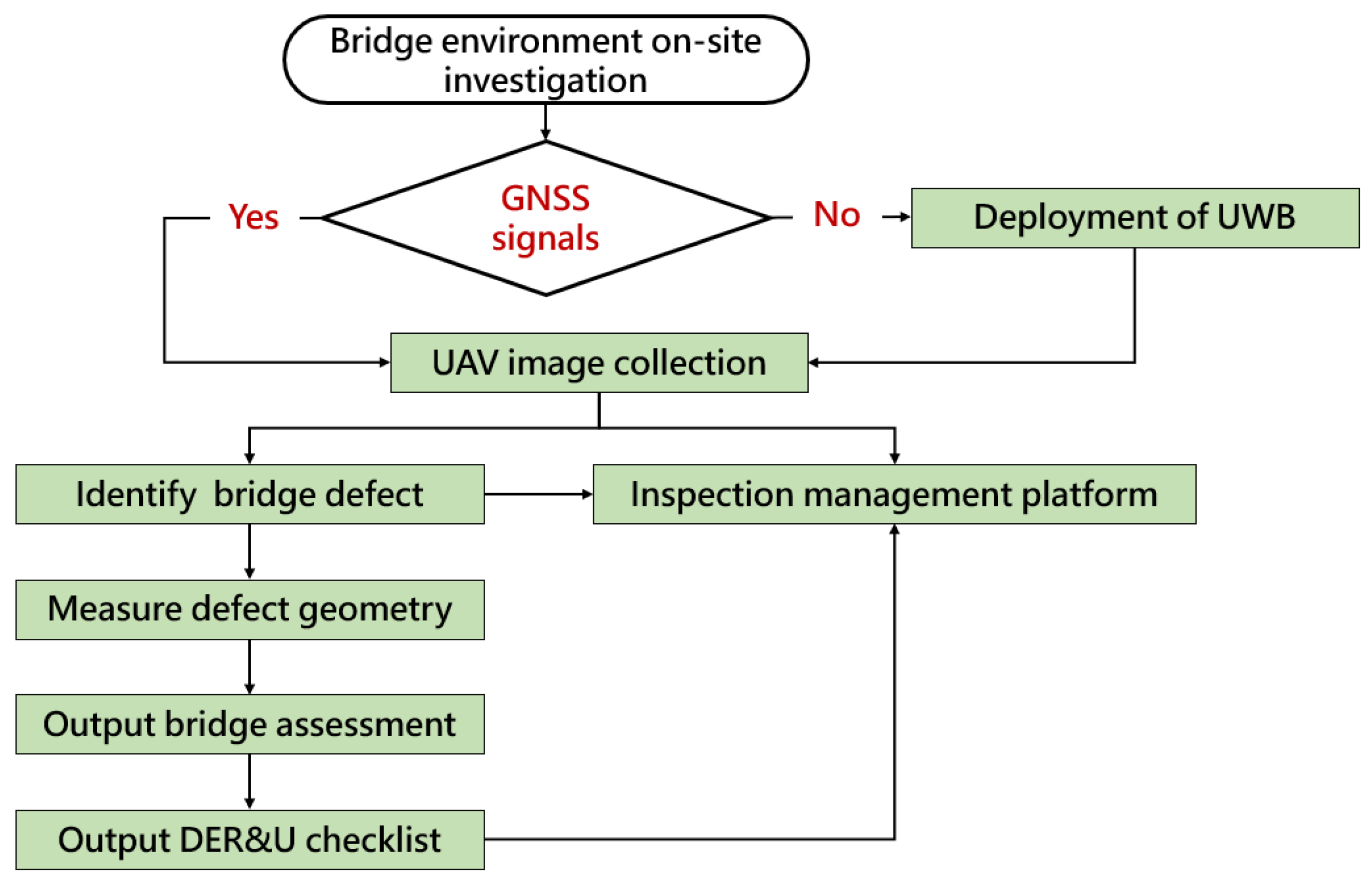
Firstly, a quick survey of the selected area is conducted to determine whether it lacks GNSS signals. GNSS signals are often missing when bridge inspections are conducted under the bridge. If GNSS signals are missing, a UWB network is deployed in the area to enable drones to fly and capture images of crucial components, such as the main beams and bridge deck panels. Then, an AI model is employed to detect defects such as "cracks", "spalling“, and "exposed rebar" in the captured images. Subsequently, the images are processed using geometric extraction methods in combination with rating criteria specified by regulations. This process yields corresponding evaluation integers of DER&U, including the Degree of deterioration, the Extent of deterioration, and the Relevancy, which are utilized to assess the severity of the structural safety impact and propose a classification of Urgency of repairing. Ultimately, the results obtained above are summarized on the inspection platform.
2.1. Data Acquisition Using UAV
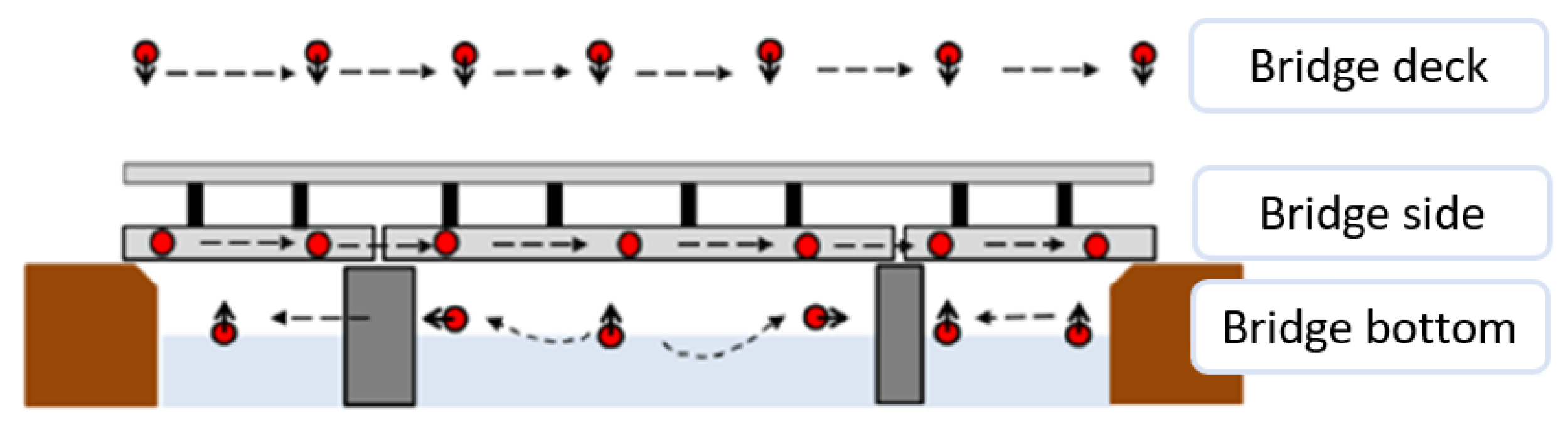
To enable the drone to autonomously navigate along a predefined path for capturing the appearance of the bridge structure, this study employs the open-source software Mission Planner to generate a flight path that is readable for the drone. Fig. 2 illustrates the planning process for capturing UAV images along the predefined path. Throughout the path planning phase, it is imperative to ensure that the captured images adhere to subsequent evaluation criteria, encompassing scale, geometric transformation, and coordinate data. To fulfill the prerequisites of bridge inspection, this study captures images at specific points, including the bridge deck, both sides of the bridge, and beneath the structure.
Figure 2.
Schematic diagram of UAV flight paths.
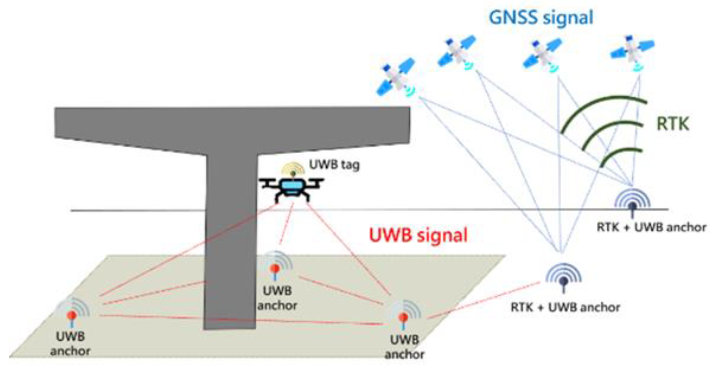
Moreover, due to the absence of GNSS signals under the bridge, a UWB network must be deployed to facilitate UAVs in capturing crucial components such as beam webs, transverse diaphragms, and supports. As shown in Fig. 3, the UWB network consists of many UWB anchors. Some of these are located outside the bridge, where their precise coordinates can be obtained using RTK (real-time kinematic) technology. Others may be located under the bridge, where GPSS is missing. Nonetheless, those RTK-equipped anchors outside the bridge can accurately determine their coordinates. A UWB tag sensor is installed on the drone to receive distance data from the anchors. Leveraging the method proposed in this study (Section 3) and the open source toolkit MAVProxy enables the drone to localize itself in GPS-denied areas.
Figure 3.
UWB technical operation diagram.
2.2. Automatic Detection of Damaged Structures
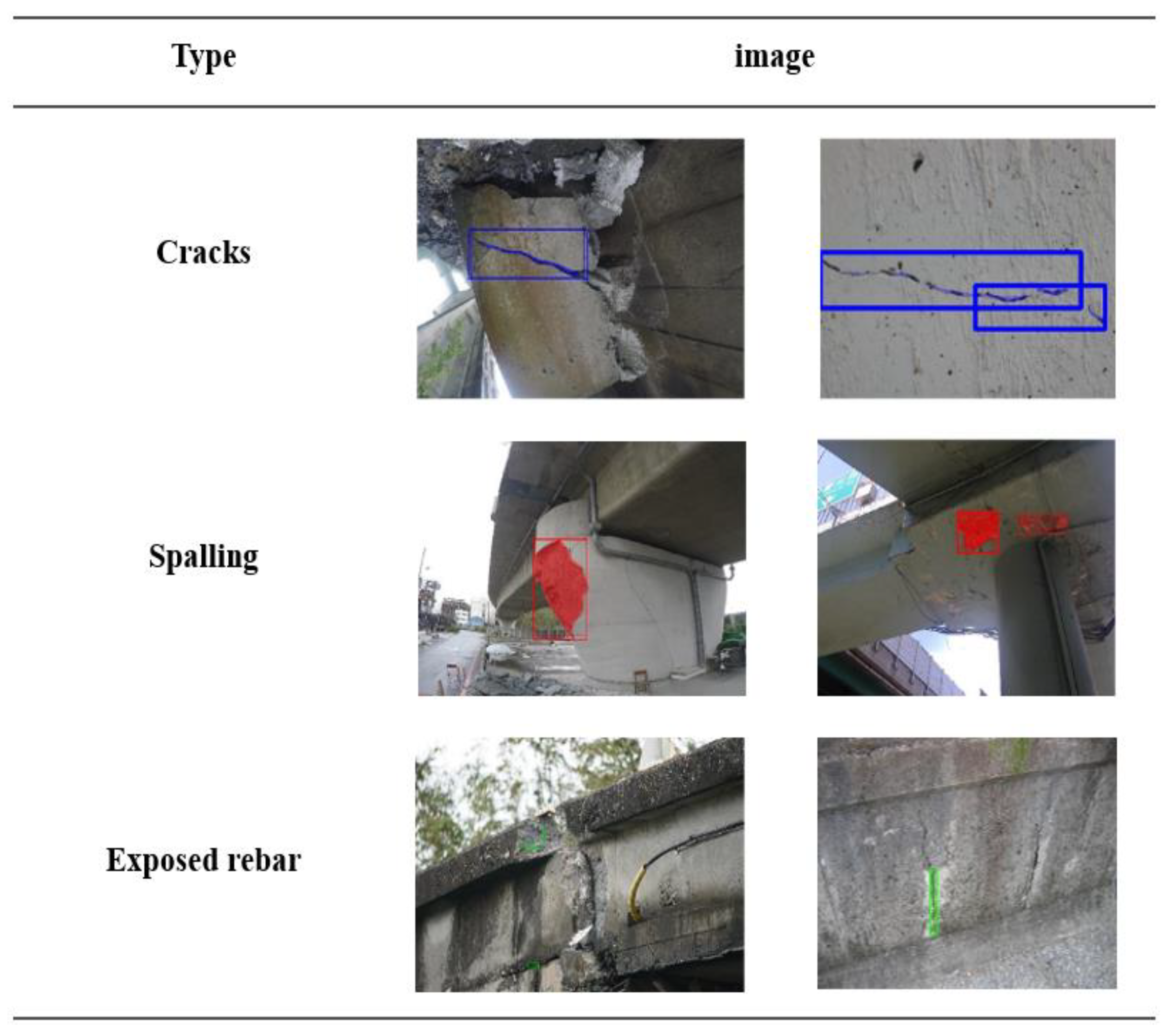
To accurately identify the damaged parts of the bridge, this study employs Mask R-CNN [33] as our training model. For training data, we collect information from the open source dataset [34] and data provided by Taiwan CECI Engineering Consultants Inc. This data covers various regions, including vehicular bridges, pedestrian footbridges, and river crossings. This study mainly assesses problems such as concrete cracks, damage, and exposed steel bars, as shown in Fig. 4. After filtering, approximately 800 images remained, chosen as training data. These images are then divided into training and validation set at a ratio of 9:1.
Figure 4.
Main problems to be assessed in bridge inspection.
During the training phase, we implement a trial approach, where the learning rate increases as the training iterations progress. After numerous experiments, the optimal parameters for the model are determined to be a batch size of 4, a learning rate of 0.0002, and 80 epochs.
2.3. Detection Results to the Inspection Checklists
In the previous subsection, we employed AI deep learning techniques to identify bridge components and defects. This identification is then further analyzed according to the DER&U values obtained through the rating criteria, which allows us to assess the severity of the structure and propose an urgency classification. Based on this classification, maintenance personnel prioritize inspections of higher-severity locations and develop a repair and reinforcement plan. In addition, due to differences in bridge shape, size, color, location, etc., applying this method requires collaboration with professional engineers to adjust the defined rules or add exception criteria for special situations.
2.4. Build a Detection Management System
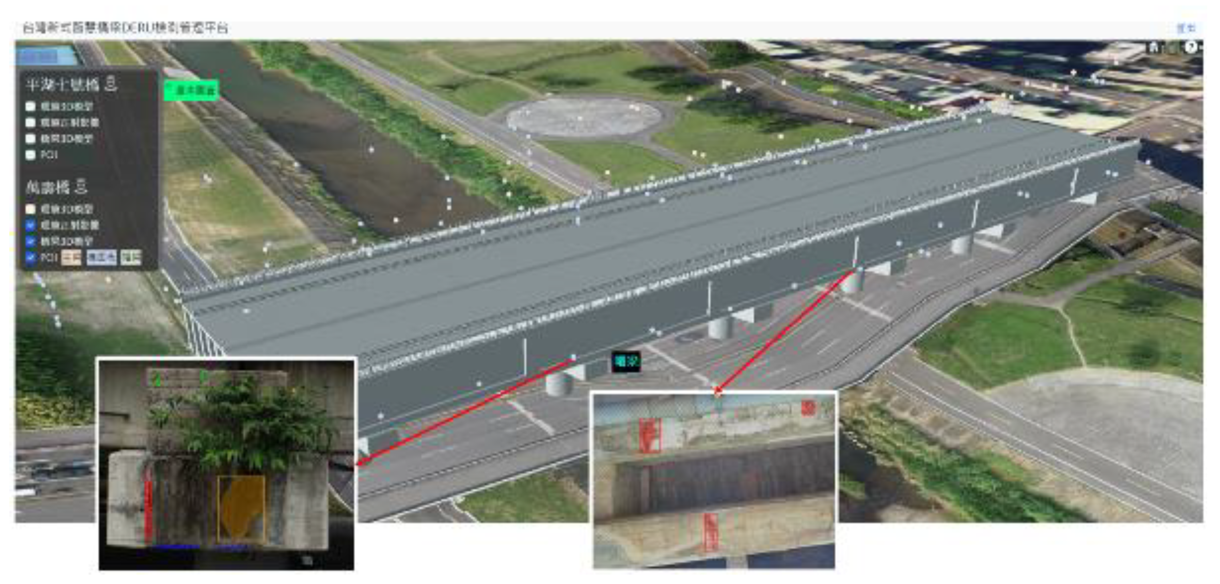
By integrating images captured by drones at points of interest with the identification results from AI models, we can construct a comprehensive three-dimensional (3D) bridge management system (refer to Fig. 5). This system not only showcases the 3D model of the bridge and its associated facilities, but can also promptly display cracks or concrete spalling on the structure, allowing maintenance personnel to initially understand the bridge condition and reduce their burden.
Figure 5.
3D bridge management system.
3. Positioning by Anchors Handover and SVD-Enhanced Method
3.1. Statement of the Handover Problem
In view of the problems caused by the large number of anchors under the bridges, the idea of “handover” is proposed to achieve precise positioning by timely controlling the switching of anchors in different areas. This ensures that the tag can accurately identify which anchor number is sending the message, allowing for precise positioning.
3.1.1. Method
A communication network is established between the tag and anchors, allowing any anchor to be controlled by the tag's position at any given time. Each UWB tag and anchor is equipped with a Raspberry Pi. All Raspberry Pis are configured to operate under the same wireless local area network (WLAN), enabling the tag to communicate with each anchor using the UDP protocol. In addition, each anchor is equipped with a relay that can be switched on and off as needed. Each group of anchors within specific areas is assigned a predefined letter, and an alphabetic reference table is established accordingly. The tag then switches these anchors on and off by sending the corresponding letter to anchors based on its location (determined by the SVD-enhanced two-stage method described later). Based on the drone’s location, the on-off mechanism will be executed to ensure that the anchors in the appropriate group are activated to locate the drone, while others are de-activated.
An optimization algorithm for anchor deployment and ID assignment has been developed to adapt the UWB handover system to bridge inspection [28]. It solves three main issues: (1) occlusion by the bridge which has many beams and columns and the effective range of UWB being than 40 m according to actual measurements; (2) deployment cost reduction by reducing the number of anchors that is deployed, even if the UWB signal covers the area under the bridge; and (3) the limited number of anchors that can be assigned at one time. Different IDs must be assigned to different anchors in the same group to avoid ranging interference between anchors.
3.1.2. Experiment
The anchors are deployed within a 10.47 m x 3.22 m area, as shown in Fig. 6. The drone’s area is divided into three zones, each of which can be located by four anchors. Although there are eight anchors, they only need to be assigned four ID’s (labeled as ID 1, 2, 3, and 4) to avoid duplication of ID’s in each zone. When the tag resides in a certain zone, the anchors within that zone are activated, while the remaining anchors are deactivated.
Figure 6.
Experimental configuration diagram. The DUT moves in the direction of the dashed arrow. While it is in Zone_A, anchors that have corresponding character A are turned on, while others off.
Figure 6.
Experimental configuration diagram. The DUT moves in the direction of the dashed arrow. While it is in Zone_A, anchors that have corresponding character A are turned on, while others off.
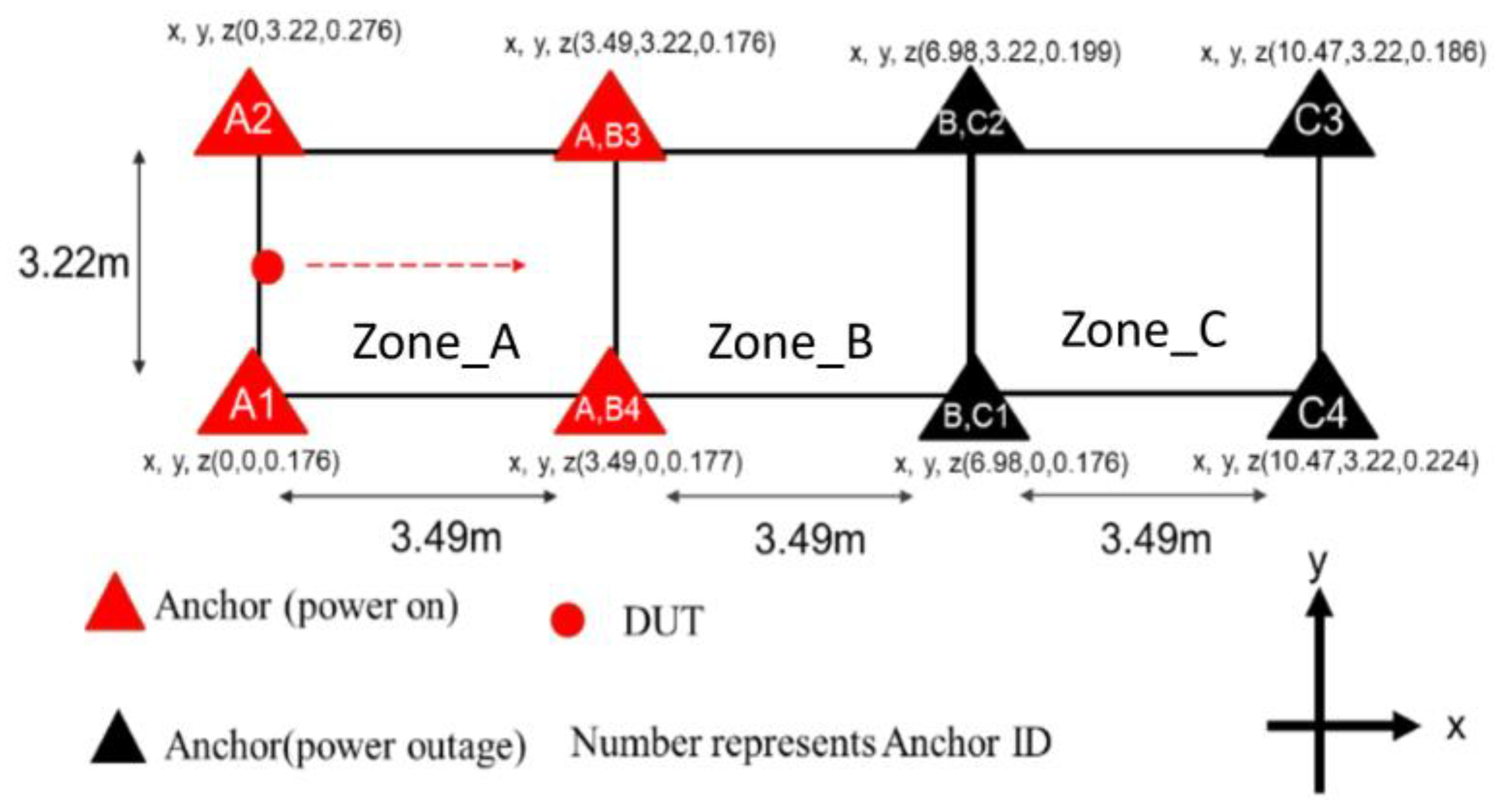
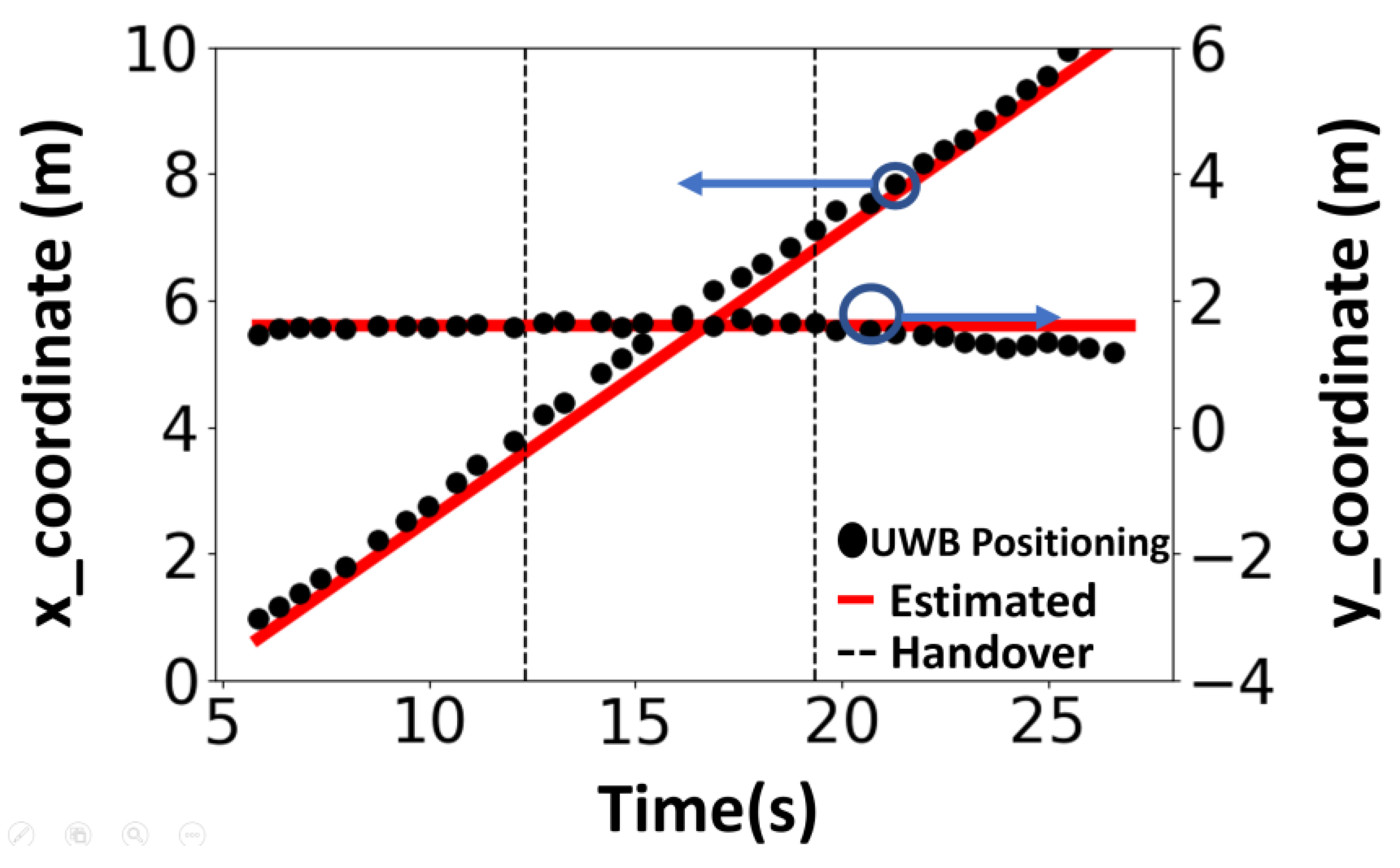
During the experiment, the experimenter, carrying the Tag, walked along a straight path from coordinates (0, 1.61) to (11.44, 1.61). The handover mechanism was activated according to the tag's position, and the positioning results were recorded throughout the experiment for subsequent analysis. The positioning results, shown in Fig. 7, demonstrate continuous positioning throughout the handover process. The horizontal axis represents time, and the vertical axes represent the x and y coordinates in meters. The red lines denote the estimated location of the DUT, the black dots denote the actual positioning solution, and the black dashed line marks the time point of handover. By comparing the estimated position with the actual routes, the positioning accuracy can be estimated, with an RMSE of 0.176 m and 0.102 m for x and y coordinates, respectively.
Figure 7.
The x-y coordinates of the positioning results. The DUT moves along x direction. The estimated position (x, y) over time is plotted using UWB measurement with handover and compared to the estimated route (red lines).
Figure 7.
The x-y coordinates of the positioning results. The DUT moves along x direction. The estimated position (x, y) over time is plotted using UWB measurement with handover and compared to the estimated route (red lines).
3.2. SVD-Enhanced Positioning in Slant Terrains
A two-stage method was originally introduced to locate the position of a drone using a UWB device [25]. In the first stage, trilateration is used to determine the x and y coordinates, which are then substituted into a predefined cost function to obtain the z coordinate. In real-world scenarios such as bridge inspection, uneven terrain limits the placement of anchors to accessible heights, usually near human working levels. When anchors are placed at different heights, the prediction accuracy drops significantly, mainly due to a large condition number.
3.2.1. Method
To reduce positioning errors caused by tilted anchor configurations, an improved UWB positioning algorithm based on SVD is developed [28]. It is found that if the anchors are nearly coplanar on sloping terrain, the unequal altitudes of the anchors will seriously contaminate the accuracy of the horizontal coordinates, resulting in inaccurate positioning of the DUT. To overcome this difficulty, the coordinate system of the anchors is transformed by rotation to a new coordinate system so that the anchors are dominantly in a horizontal plane with minimum vertical altitude span. Then, the two-stage algorithm is applied in the new coordinate system, where the horizontal coordinates of the tag are found in the first stage and the vertical height in the second stage. Finally, the new coordinates are converted back to the original coordinate system to obtain the tag position.
In a positioning scenario with or more anchors, let the coordinates of the DUT at point T and the coordinates of the anchors be (,) for . Choosing one anchor, say , as the reference, the anchor configuration can be characterized by a matrix consisting of vectors Apply SVD to decompose matrix into the form of , where is a diagonal matrix of singular values. Let the solution for the DUT be . This transformation shifts all computations to the domain, allowing us to express as . Therefore, the x’ and y’ coordinates of the solution are no longer adversely affected by the large condition number. The second stage of the two-stage method [25] is then performed to obtain the expected value of by giving the accurate and . Finally, the solution can be determined using .
3.2.2. Experiment
A set of UWB anchors with IDs 1-4 are located within a 27 m × 4.83 m area. To mimic the bridge’s downhill terrain, anchors 1 and 2 are placed at a lower elevation, while anchors 3 and 4 are placed at a higher elevation, with tilt angle θ = 3.4 degree (see Fig. 8). In Fig. 8, the red points correspond to anchors labeled 1-4 and the experimenter, carrying a tag, walked along the blue rectanglar path from P1, P4, P3, P2, and back to P1. Through the enhanced two-stage method, the tag position can be determined.
Figure 8.
Anchor positions and walking path on tilted plane.

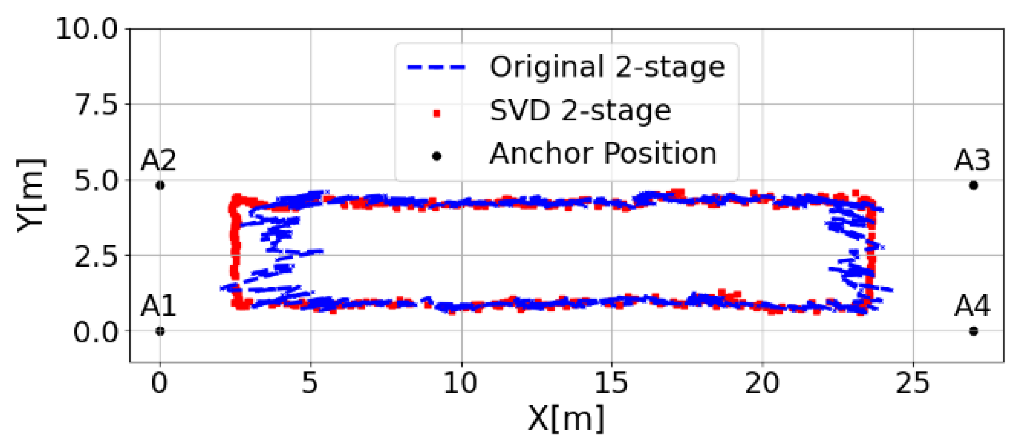
The effect of the large condition number on positioning results is also investigated. At a tilt angle of θ = 3.4, the condition number is 606 and the smallest singular value = . This small value indicates high sensitivity to measurement errors, which can significantly affect 2D positioning results. Fig. 9 shows a comparison of 2D positioning results for the original and enhanced two-stage methods. Using SVD significantly improves x-y positioning accuracy and reduces the error amplification caused by the high condition number. This real-world positioning experimental finding highlights the effectiveness of the enhanced two-stage method in maintaining high positioning accuracy even when the anchors are not placed on a flat surface.
Figure 9.
Comparison of original and SVD two-stage methods for 2D positioning at
4. Bridge Inspection Experiment
4.1. Experiment Settings
4.1.1. Hardware
The hardware is shown in Fig. 10. The UAV has a three-axis gimbal primarily mounted upward to fulfill the inspection requirements beneath the bridge. In addition, it is equipped with a video transmission transmitter and receiver module to facilitate long-distance wireless transmission of aerial footage captured by the drone. This model also boasts a wind resistance capability equivalent to Beaufort scale 4, ensuring that it is suitable for handling sudden strong winds that may occur under the bridge.
Figure 10.
Hardware used in the experiment. (a) UAV, and (b) UWB sensor.
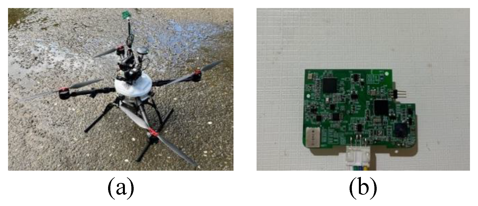
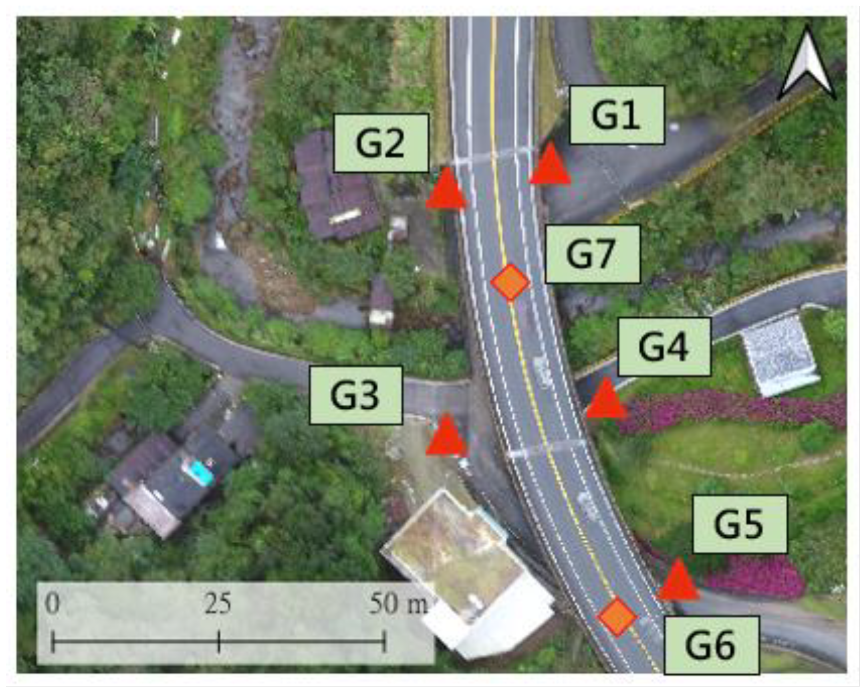
The UWB used in this experiment supports IEEE 802.15.4a and offers multiple channels. We primarily operate within the channel range of 4.25 GHz to 4.75 GHz, with a packet transmission rate of 50 Hz. In this experiment, UWB anchors are deployed outside or under the bridge. First, the longitude and latitude coordinates of the anchors outside the bridge are measured using RTK technology. With the above information, the coordinates of other anchors under the bridge can be obtained using the positioning algorithm (see Fig. 11).
Figure 11.
Anchor coordinates G1-G5 are determined via VRS-RTK, while G6-G7 coordinates are obtained using a positioning algorithm based on G1-G5.
Figure 11.
Anchor coordinates G1-G5 are determined via VRS-RTK, while G6-G7 coordinates are obtained using a positioning algorithm based on G1-G5.
4.1.2. Software
The drone’s flight control system uses Pixhawk, which is supported by the open-source firmware Ardupilot. This tool enables us to leverage a range of packages to facilitate various tasks in this experiment. For instance, we can utilize the package GPSInput of MAVProxy to simulate GPS signals to achieve drone positioning. Additionally, tools like Mission Planner can be used to set flight paths and monitor the drone's flight in real time.
4.2. Selection of Validation Bridges
This study selected two bridges for experimental validation: a small bridge, Bridge A, located in a mountainous area, and a river-crossing bridge, Bridge B, in an urban area.
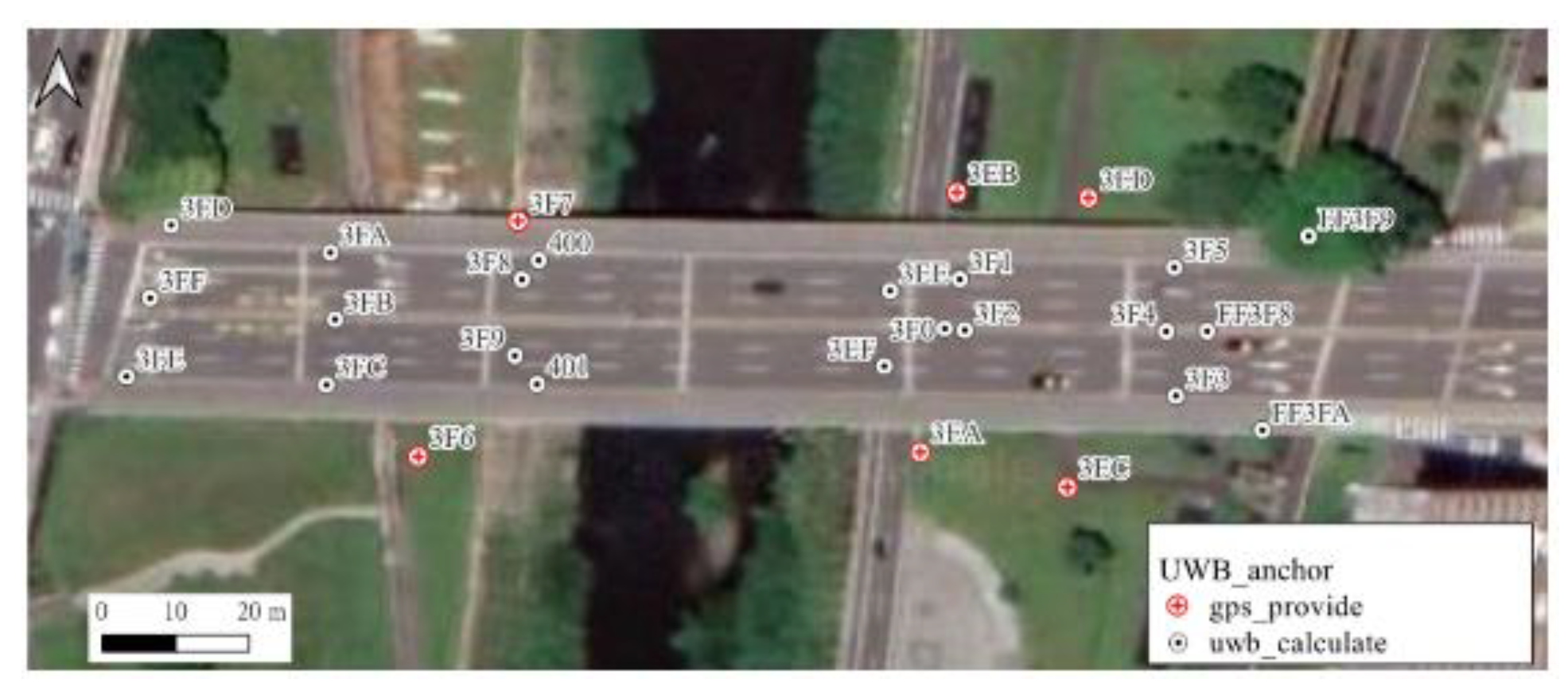
These two bridges were selected based on specific considerations. According to the Taiwan Ministry of Transportation's "National Bridge Basic Information Table," Bridge A requires drone inspections because its minimum underpass height is 1.2 m, making it difficult for large equipment to enter. Bridge B, a vital role as a transportation link connecting downtown Taipei with its suburbs, spans the Jingmei River, measuring 166 m in length and 29.5 m in width. The bridge piers are in the stream, making traditional bridge inspection difficult. Figs. 11 and 12 describe the UWB network deployment for Bridges A and B, respectively.
Figure 12.
The 166-meter-long bridge is deployed with a total of 27 UWB anchors along its span.
4.3. Image Acquisition
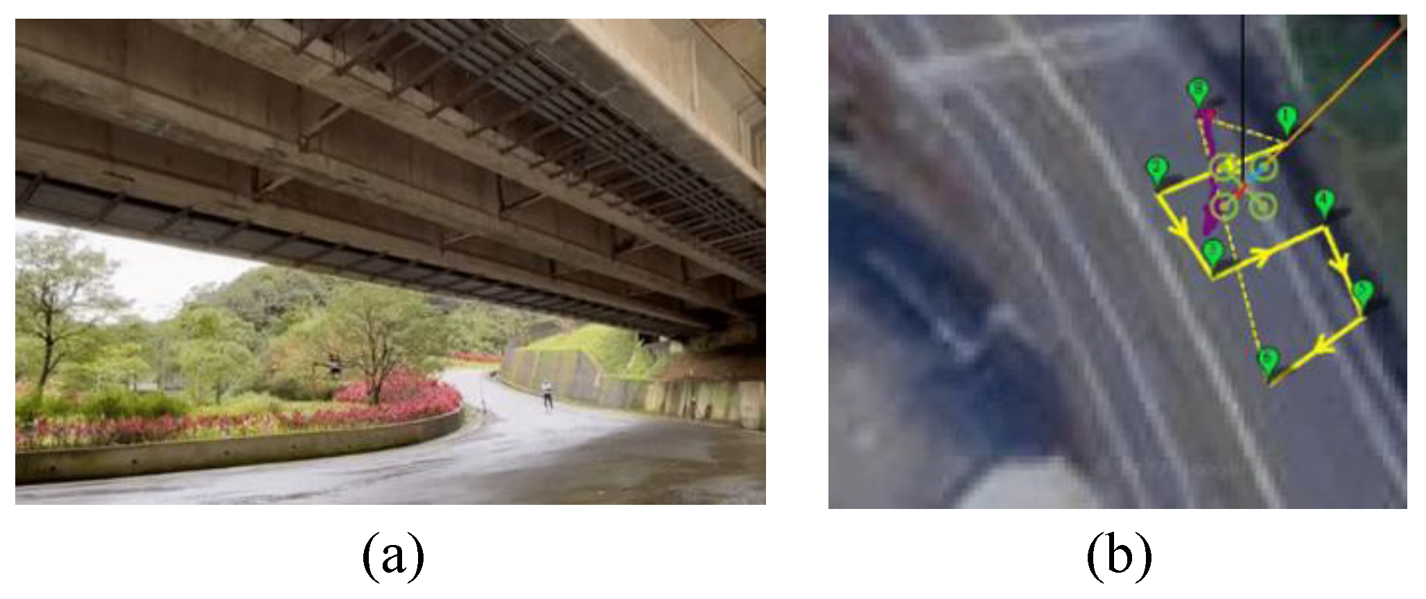
For drone image acquisition, this study uses Mission Planner to generate flight paths compatible with the drone, and save them in the .waypoint file format. This planning process involves pre-defining the drone’s shooting path for key bridge components and setting parameters such as altitude, flight speed, and dwell time at waypoints to ensure that the drone's flight trajectory aligns with site requirements during route planning. Fig. 13 illustrates the drone’s flight path around and under a bridge as an example. The actual flight path, as shown by the purple line in the figure, is in good agreement with that defined by the Mission Planner.
Figure 13.
(a) Drone's flight trajectory (b) Pre-defining path via Mission Planner. The purple line represents the actual flight path of the drone.
Figure 13.
(a) Drone's flight trajectory (b) Pre-defining path via Mission Planner. The purple line represents the actual flight path of the drone.
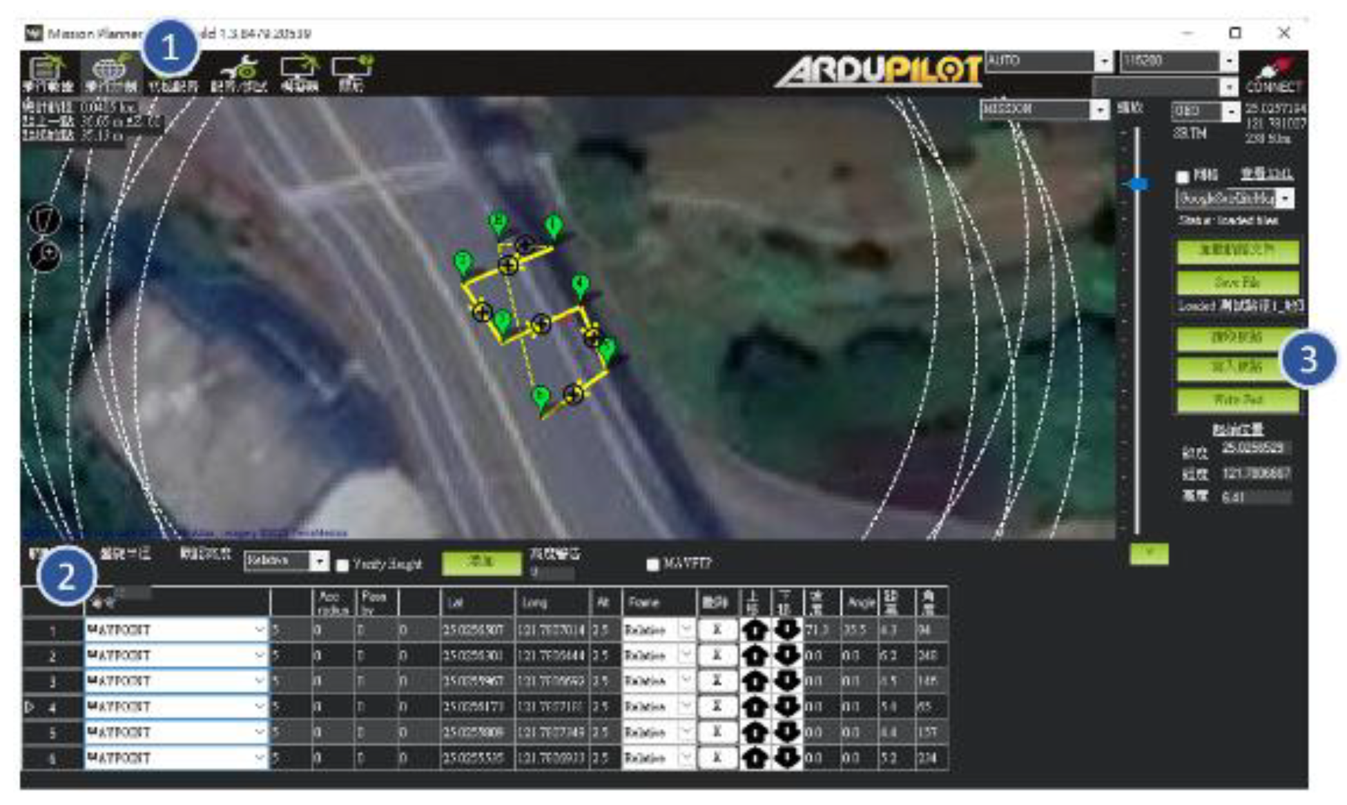
Drone route planning involves three main steps, as shown in Fig. 14. First, as (1), switch the Mission Planner screen to the "Flight Plan" page and designate the return position (H). By default, the drone will autonomously return to this position after completing its mission. Next, as (2), select the waypoint locations to chart the route. Once the location of each waypoint is confirmed, proceed to set the dwell seconds and altitude (Alt) for each point. In this case, the route required the drone to pause for 5 seconds at each point, and the altitude was set to 2.5 m. The altitude specified here is relative to the initial position. Finally, as (3), upload the planned route to the drone to perform the mission.
Figure 14.
Illustration of a task comprising six waypoints.
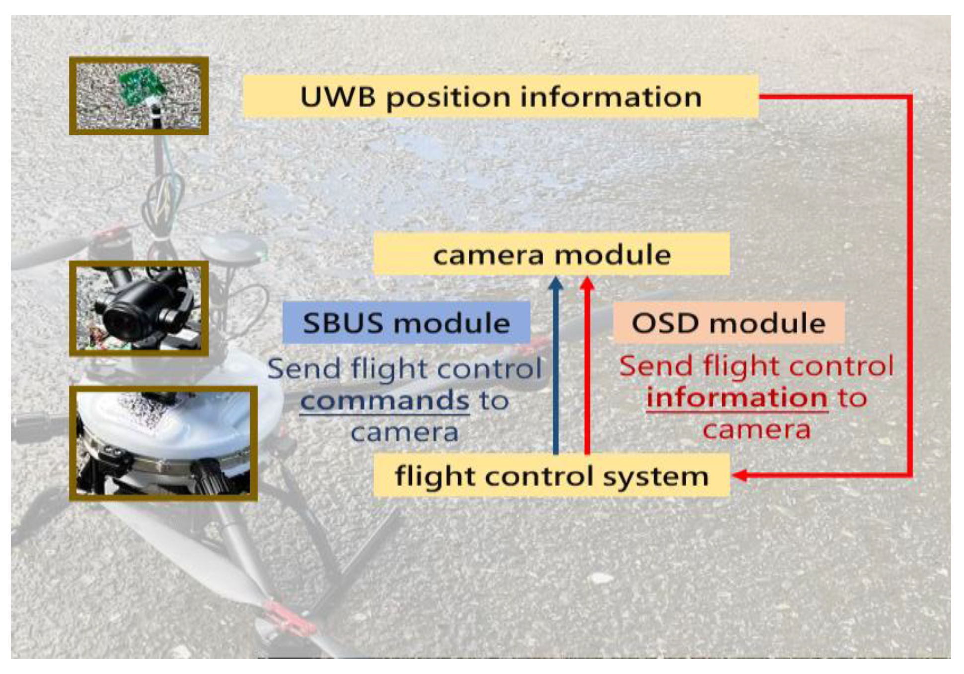
To issue commands for capturing images through the Mission Planner and embed the coordinate information provided by UWB into the image, this study employed an on-screen display (OSD) module and a serial bus (SBUS) signal conversion module to facilitate the UAV imaging process (see Fig. 15). This process is primarily divided into two parts: transmitting flight control information to the camera module (red section) and issuing flight control instructions for image capture (blue section).
Figure 15.
The framework for embedding coordinates into UAV images.
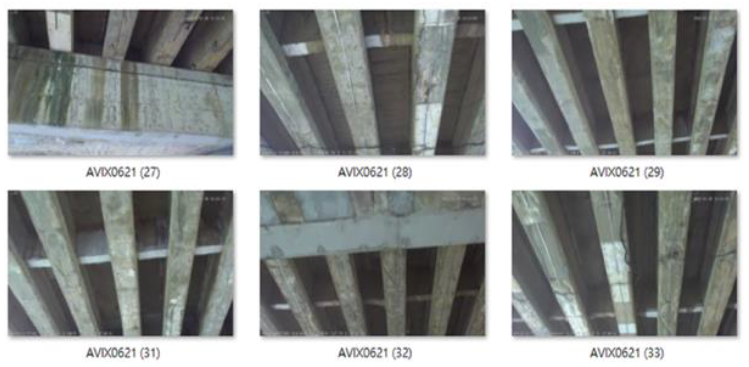
Finally, the drone performed the shooting task according to the pre-defined paths and obtained images of each bridge component. Fig. 16 shows images captured through the pre-planned flight paths. Coordinate information is embedded in each image, allowing the results to be subsequently mapped to actual locations.
Figure 16.
Images captured by UAV for the inspection of Bridge B.
5. Conclusions and Discussion
The structural safety of bridges is a critical public concern. However, traditional visual inspection methods are labor-intensive and time-consuming. This study is dedicated to the research and development of key technologies for bridge inspection. In terms of data collection, through a comprehensive UAV route planning process, the study has completed the collection of images of several key bridge inspection components. The establishment of a UWB network addresses the difficulty of UAVs collecting images from under bridges, representing a significant breakthrough in autonomous image collection. The study has deployed a UWB environment on Bridges A and B, successfully improving the UAV's position accuracy to 0.2–0.5 meters. Through route planning, the study automatically collects images of key bridge components previously difficult for UAVs to capture, including supports and beam webs.
Another core aspect of this project is UAV image processing and analysis management. This bridge inspection framework, based on deep learning and computer vision, assists engineers in conducting bridge inspections quickly and efficiently. This AI recognition process is divided into three modules: image localization, degradation identification, and damage assessment. It can more effectively assess problems such as concrete cracks, damage, and exposed steel bars. Compared to previous research on degradation identification, this focuses more on establishing a comprehensive bridge inspection framework to assist engineers in patrol inspections. Inspection results from the two practical bridges demonstrate that UAVs, by collecting a wider range of inspection angles, reveal more deterioration areas than visual inspections, providing on-site personnel with a more comprehensive basis for bridge repairs.
Still, this study does not consider certain real-world scenarios, such as the presence of beams and columns beneath bridges, which may block or diffract UWB signals during UAV flight, thus affecting positioning accuracy. Therefore, detecting UWB signal outliers is an important consideration for future bridge inspection methods. On the other hand, for long-span bridges, determining the optimal locations of anchors under the bridges while ensuring precise positioning is also an essential issue. Overall, there may be other factors not discussed here that need to be considered in real-world scenarios. However, by addressing the issues raised, bridge inspection technology can advance further.
Author Contributions
Conceptualization, J.Y. and R.B.; methodology, R.B.; software, J.H. and J.Y.; validation, J.Y. and R.B.; formal analysis, J.H.; investigation, R.B.; resources, R.B.; data curation, J.H.; writing—original draft preparation, J.H.; writing—review and editing, R.B.; visualization, J.H and J.Y.; supervision, J.Y. and R.B.; project administration, R.B.; funding acquisition, R.B. All authors have read and agreed to the published version of the manuscript.
Funding
This research was funded jointly by the Ministry of Science and Technology, Taiwan, under grant MOST 110-221-E-0020172 and the Xin Tai Asset Management Co., Ltd., Taipei, Taiwan.
Data Availability Statement
The original contributions presented in this study are included in the article. Further inquiries can be directed to the corresponding author.
Acknowledgments
J. J. Bai thanks C. R. Hsu, P. X. Wang and J. L. Tsai for providing the experimental data for this paper.
Conflicts of Interest
The authors declare no conflicts of interest.
References
- Vera, A. Concrete bridge railing collapses onto Tennessee interstate, injuring one person. CNN, 2019.
- Lin, J.J.; Ibrahim, A.; Sarwade, S.; Golparvar-Fard, M. Bridge inspection with aerial robots: Automating the entire pipeline of visual data capture, 3D mapping, defect detection, analysis, and reporting. J. Comput. Civ. Eng. 2021, 35(2), p. 04020064. [CrossRef]
- Morgenthal, G.; Hallermann, N.; Kersten, J.; Taraben, J.; Debus, P.; Helmrich, M.; Rodehorst, V.; Framework for automated UAS-based structural condition assessment of bridges. Autom. Constr. 2019, 97, 77-95. [CrossRef]
- Yang, Y; Khalife, J.; Morales, J.J.; Kassas, M. UAV waypoint opportunistic navigation in GNSS-denied environments. IEEE Trans. Aerosp. Electron. Syst. 2021, 58 (1), 663-678. [CrossRef]
- Khalife, J.; Kassas, Z.M. On the achievability of submeter-accurate UAV navigation with cellular signals exploiting loose network synchronization. IEEE Trans. Aerosp. Electron. Syst. 2022, 58(5), 4261-4278. [CrossRef]
- Khalife, J.; Kassas, Z.M., Opportunistic UAV navigation with carrier phase measurements from asynchronous cellular signals, IEEE Trans. Aerosp. Electron. Syst. 2019, 56(4), 3285-3301. [CrossRef]
- Tomiczek, A.P.; J. Bridge, J.A.; Ifju, P.-G.; Whitley T.J. Small unmanned aerial vehicle (sUAV) inspections in GPS denied area beneath bridges. Struct. Congr. 2018, 205-216.
- Whitley, T.; Tomiczek, A.; Tripp, C.; Ortega, A.; Mennu, M.: Bridge J.;, P. Ifju, Design of a small unmanned aircraft system for bridge inspections, J. Sens. 2020, 20(18), 5358, 2020. [CrossRef]
- Abiko, S.; Sakamoto, S.Y.; Hasegawa, T.; Shimaji, N. Development of constant altitude flight system using two dimensional laser range finder with mirrors. In Int. Conf. Adv. Intelligent Mechatron. (AIM) 2017. [CrossRef]
- Petritoli, E.; Leccese, F.; Leccisi, M. Inertial navigation systems for UAV: Uncertainty and error measurements. In 5th Int. Workshop Metrology AeroSpace (MetroAeroSpace) 2019. [CrossRef]
- Scaramuzza, D.; Zhang, Z. Visual-inertial odometry of aerial robots. 2019. [Online]. Available: arXiv:1906.03289.
- Zhang, J.; Wu, Y.; Liu, W.; Chen, X. Novel approach to position and orientation estimation in vision-based UAV navigation. IEEE Trans. Aerosp. Electron. Syst. 2010, 46(2), 687-700. [CrossRef]
- Balamurugan, G.; Valarmathi, J.; Naidu, V.P.S. Survey on UAV navigation in GPS denied environments. In Int. Conf. Signal Processing, Comm., Power Embedded Syst. (SCOPES) 2016.
- Mansur, S.; Habib, M.; Pratama, G.N.P.; ahyadi, I.A.; and . I. Ardiyanto, I. Real time monocular visual odometry using optical flow: study on navigation of quadrotors UAV. In 3rd Int. Conf. Sci. Technol.-Computer (ICST) 2017.
- El Bouazzaoui, I.; Florez, S.A.R.; El Ouardi, A. Enhancing RGB-d SLAM performances considering sensor specifications for indoor localization. IEEE Sensors J. 2021, 22(6), 4970–4977. [Google Scholar] [CrossRef]
- Warren, M.; Corke, P.; Upcroft, B. Long-range stereo visual odometry for extended altitude flight of unmanned aerial vehicles. Int. J. Robot. 2016, 35(4), 381–403,. [Google Scholar] [CrossRef]
- Shan, M.; Bi, Y.; Qin, H.; Li, J.; Gao, Z.; Lin, F.; Chen, B.M. A brief survey of visual odometry for micro aerial vehicles. In 42nd Annu. Conf. Industrial Electron. Society 2016.
- Thai, V.P.; Zhong, W.; Pham, T.; Alam, S.; Duong, V. Detection, tracking and classification of aircraft and drones in digital towers using machine learning on motion patterns. In Conf. Integrated Comm., Navigat. Surveillance (ICNS) 2019.
- Campos, C.; Elvira, R.; Rodríguez, J.J.G.; Montiel, J.M.; Tardós, J.D. Orb-slam3: An accurate open-source library for visual, visual–inertial, and multimap slam. IEEE Trans. Robot. 2021, 37(6), 1874–1890. [Google Scholar] [CrossRef]
- Qin, T.; Li, P.; Shen, S. Vins-mono: A robust and versatile monocular visual-inertial state estimator. IEEE Trans. Robot. 2018, 34(4), 1004–1020. [Google Scholar] [CrossRef]
- Bryson, M.; Sukkarieh, S. Observability analysis and active control for airborne SLAM. IEEE Trans. Aerosp. Electron. Syst. 2008, 44(1), 261–280. [Google Scholar] [CrossRef]
- Alkendi, Y.; Seneviratne, L.; Zweiri, Y. State of the art in vision-based localization techniques for autonomous navigation systems. IEEE Access 2021, 9, 76847–76874. [Google Scholar] [CrossRef]
- Ali, R.; Kang, D.; Suh, G.; Cha, Y.J. Real-time multiple damage mapping using autonomous UAV and deep faster region-based neural networks for GPS-denied structures. Autom. Constr. 2021, 130, 103831. [Google Scholar] [CrossRef]
- Jiang, S.; Wu, Y.; Zhang, J. Bridge coating inspection based on two-stage automatic method and collision-tolerant unmanned aerial system. Autom. Constr. 2023, 146, 104685. [Google Scholar] [CrossRef]
- Chen, Y.-E.; Liew, H.-H.; Chao, J.-C.; Wu, R.-B. Decimeter-accuracy positioning for drones using two-stage trilateration in a GPS-denied environment. IEEE Internet Things J. 2022, 10(9), 8319–8326. [Google Scholar] [CrossRef]
- Si, M.; Wang, Y.; Zhou, N.; Seow, C.; Siljak, H. A hybrid indoor altimetry based on barometer and UWB. J. Sens. 2023, 23(9), 4180. [Google Scholar] [CrossRef]
- Nguyen, T.M.; Zaini, A.H.; Guo, K.; Xie, L. An ultra-wideband-based multi-UAV localization system in GPS-denied environments. In Int. Conf. Micro Air Vehicles 2016.
- Wang, P.-H.; Wu, R.-B. An ultra-wideband handover system for GPS-free bridge inspection using drones. Sensors 2025, 25(6), 1923. [Google Scholar] [CrossRef]
- Wang, Y.; Li, X. The IMU/UWB fusion positioning algorithm based on a particle filter. ISPRS Int. J. Geo-Inf 2017, 6(8), 235. [Google Scholar] [CrossRef]
- Foy, W.H. Position-location solutions by Taylor-series estimation. IEEE Trans. Aerosp. Electron. Syst. 1976, 2, 187–194. [Google Scholar] [CrossRef]
- Chan, Y.T.; Ho, K.C. A simple and efficient estimator for hyperbolic location. IEEE Trans. Signal Process. 1994, 42(8), 1905–1915. [Google Scholar] [CrossRef]
- Tsai, C.-L.; Wu, R.-B. Enhanced UAV localization and outlier detection using SVD-enhanced UWB for bridge inspections. IEEE Internet Thing J. 2025, 12(16), 33111–33119. [Google Scholar] [CrossRef]
- He, K.; Gkioxari, G.; Dollár, P.; Girshick, R. Mask r-cnn.. In Proc. Int. Conf. Computer Vision 2017.
- Neuhold, G.; Ollmann, T.; Bulo, S.R.; Kontschieder, P. The mapillary vistas dataset for semantic understanding of street scenes. In Proc. Int. Conf. Computer Vision 2017.
Disclaimer/Publisher’s Note: The statements, opinions and data contained in all publications are solely those of the individual author(s) and contributor(s) and not of MDPI and/or the editor(s). MDPI and/or the editor(s) disclaim responsibility for any injury to people or property resulting from any ideas, methods, instructions or products referred to in the content. |
© 2025 by the authors. Licensee MDPI, Basel, Switzerland. This article is an open access article distributed under the terms and conditions of the Creative Commons Attribution (CC BY) license (https://creativecommons.org/licenses/by/4.0/).
Copyright: This open access article is published under a Creative Commons CC BY 4.0 license, which permit the free download, distribution, and reuse, provided that the author and preprint are cited in any reuse.


