
Submitted:
04 September 2025
Posted:
04 September 2025
You are already at the latest version
Abstract
Wood-based materials in the form of wood veneer composites (WVC) possess a high lightweight construction potential for load-bearing applications in mechanical engineering due to their high strength properties combined with low density. However, in order to substitute energy-intensive metallic construction materials (such as steel or aluminum), additional structural space is required to compensate for the comparatively low stiffness by means of the area moment of inertia. Under bending loads, an increase in cross-sectional height at a constant span length leads to elevated shear stresses. Owing to the low shear strength and stiffness of wood-based materials, the influence of shear stresses must be considered in both the design of wooden components and in material testing. Current standards for determining the bending properties of wood-based materials only describe methods for assessing pure bending behavior, without accounting for shear effects. The present contribution introduces a method for determining both bending and shear properties of WVC using the three-point bending test. This approach allows the derivation of bending and shear modulus values through an analytical model based on Timoshenko beam theory by testing various span-to-height ratios. These modulus values represent material constants and enable the numerical design of wooden components for arbitrary geometric parameters.
Keywords:
wood-based materials
; bending
; shear
; mechanical engineering
; material properties
1. Introduction
The main application areas of wood are in the energy and chemical sectors, the paper industry, and, in processed form as wood-based materials, in furniture and structural timber engineering [1,2,3,4,5]. In contrast, wood-based materials are currently rarely used as construction materials in technical applications of mechanical engineering. Upon closer examination, however, a few promising approaches can be identified for the use of wood-based materials in load-bearing elements, such as in automotive engineering, materials handling technology, or even in aerospace [6,7,8,9,10]. Metals, with their isotropic and homogeneous structure combined with superior mechanical properties, have outpaced the anisotropic and inhomogeneous material wood as a construction material since the onset of industrialization [11]. By processing wood into engineered wood products, particularly in the form of veneer-based composites (WVC – Wood Veneer Composites), anisotropy and inhomogeneity can be largely minimized [12,13]. These materials exhibit favorable mechanical properties while maintaining a low density, which grants them significant lightweight potential. Provided sufficient structural space is available, they allow for the substitution of energy-intensive metallic or fiber-reinforced structures, as illustrated in Figure 1 [11].
The research group Application of Renewable Materials at the Chair of Conveying and Material Handling Engineering, Chemnitz University of Technology, has set itself the goal of exploiting the lightweight potential of WVC and developing sustainable applications in the field of materials handling by means of modular timber-based construction [9]. Previous research activities have included the development of workpiece carriers, load handling devices, vertical conveyors, and frame elements [14]. In addition to compressive stresses, three-point bending has emerged as the predominant loading scenario, where, depending on the span-to-height ratio, a combined bending and shear stress condition arises [15]. It is well established that wood and WVC are shear-compliant materials, whose shear moduli and strengths are considerably lower compared to their elastic moduli and strengths under normal stresses [16,17,18,19]. In particular, shear stresses in the radial–tangential (RT) plane, referred to as rolling shear, are critical in plywood and must be explicitly accounted for in structural design verification [20]. This marks a key distinction from metallic construction materials, which exhibit shear stiffness and strength values several times higher.
The currently applicable standards, EN 408 and EN 789, for the determination of bending and shear properties of WVC, specify four-point bending tests to assess bending performance [21,22]. In this test setup, the loaded region between the two load anvils is free from shear, resulting in pure bending stresses. Shear properties, by contrast, are determined in separate tests. The equally valid standard EN 310, however, prescribes a three-point bending test method [23]. Yet, in all of these standards, a span-to-height ratio between 16 and 20 is prescribed. This specification intentionally minimizes shear stresses to the extent that their influence on the test results becomes negligible. Such an approach, however, does not reflect practical conditions for load-bearing applications in mechanical engineering. In the substitution of metallic construction materials by WVC, the span is generally fixed and cannot be altered. The cross-section, in particular height and width, remains the adjustable parameter. This adjustment is necessary because WVC, compared to metals, exhibits significantly lower elastic moduli. To compensate for this deficiency and to limit deformation, the moment of inertia must be increased, preferably by enlarging the component height. The resulting modification of the span-to-height ratio has the negative effect of increasing the influence of shear on structural behavior. As a positive side effect, however, the required cross-sectional enlargement reduces the stresses acting within the component. For this reason, in the dimensioning of WVC-based components, stiffness rather than strength constitutes the decisive criterion.
Characterizing the structural behavior of a component requires accurate knowledge of its material properties. In the case of three-point bending, these properties comprise the bending modulus and shear modulus as well as bending and shear strength. The method presented in this contribution enables the simultaneous determination of both bending and shear properties from three-point bending tests conducted with varying span-to-height ratios. Based on Timoshenko beam theory, an analytical framework can be derived to evaluate the corresponding modulus values. Once these modulus values are established for a material, the same approach can be applied to design components of arbitrary geometries.
The present contribution forms part of the research project Wood in Mechanical Engineering (HoMaBa), conducted between 2018 and 2022 [24]. Within this project, with a focus on the use of wood in mechanical engineering, the following topics were addressed:
2. Materials and Methods
The analyses presented herein were conducted on commercially available birch plywood. All individual specimens were prepared from sheet material originating from a single production batch. Table 1 summarizes the key specifications. The density was determined in accordance with EN 323 and the moisture content in accordance with EN 322 on a random selection of individual specimens; the mean values are listed in Table 1 [32,33].
Classical three-point bending tests were carried out in accordance with EN 310 [23]. All specimens had a square cross-section. In total, seven different span-to-height ratios between 5 and 20 were examined. Although the laminated structure largely minimizes anisotropy, the mechanical properties still vary depending on specimen orientation. Following the classification in EN 1995-1, a distinction was made with regard to the mid-plane orientation relative to the load direction (plate, disk) and the fiber direction of the face layers relative to the longitudinal axis of the specimen (0°, 90°) [34]. Consequently, four different configurations were tested: plate loading with the face layer fibers oriented parallel (P-0°) or perpendicular (P-90°) to the specimen length, and disk loading with the face layer fibers oriented parallel (S-0°) or perpendicular (S-90°) to the specimen length. Figure 2 summarizes the complete experimental spectrum. All tests were conducted using a Zwick/Roell Z250 testing machine with a crosshead speed of 10 mm/min. The recorded deformations correspond to the displacement of the machine traverse.
Since no optical measurement system was employed for determining deformations, the recorded deformation values were first corrected. This correction was necessary because WVC exhibits low hardness in the radial direction, leading to partial indentation of the loading anvil into the specimen. Moreover, all components of the test setup must be regarded as elastic elements that undergo minor deformations. For correction, a calibration curve was obtained by loading a specimen in compression. The deformations from this calibration curve were subtracted from the measured deformation curves. Figure 3 shows an exemplary force–displacement curve of a randomly selected specimen. The grey curve represents the uncorrected data, whereas the black curve represents the corrected data, which served as the basis for further evaluation [28].
From the corrected force–displacement curves, stress values and the global modulus of elasticity were determined. As a first step, the maximum applied load was identified, representing the failure point. In Figure 3, the failure point is marked with a red cross. Subsequently, the global modulus of elasticity was calculated in accordance with EN 789 by performing a linear regression of all measurement values within the 10–40% range of the ultimate load (Figure 3, dark green crosses) and converting the slope of the linear portion (Figure 3, green line) [22]. Finally, the yield point was determined, defined as the point where the slope of the tangent to the curve first falls below 95% of the slope of the linear regression. The stress at this point was defined as the maximum permissible stress and is indicated in Figure 3 by a blue cross. Conversion from force to stress values was carried out using standard equations for bending stress under three-point loading conditions.
As previously discussed, the global modulus of elasticity depends on the span-to-height ratio of the specimen. This dependence arises from the varying influence of shear deformation on the total specimen deflection. Testing specimens with different spans while maintaining constant specimen height enables the determination of both bending and shear moduli through nonlinear regression. Timoshenko beam theory was applied, which assumes that the total deformation is composed of bending and shear components [35]. Bending and shear deformations are considered decoupled and analyzed separately. By contrast, normative testing procedures typically neglect shear deformation and employ the special case of Euler–Bernoulli beam theory. From Timoshenko beam theory, by substituting the governing differential equations for bending and shear into the case of three-point bending, a general expression is obtained for calculating the global modulus of elasticity as a function of bending modulus, shear modulus, span, and cross-sectional parameters (area and moment of inertia), as given in Equation (3-1). Once the cross-section is specified, the corresponding formulas for cross-sectional area and moment of inertia can be substituted, simplifying the expression further. Irrespective of the cross-sectional shape, the specimen width cancels out, leaving only the span and specimen height as geometric parameters. Thus, Equation (3-1) represents the dependence of the global modulus of elasticity on the span-to-height ratio. A selection of the relevant formulas required for deriving Equation (3-1) is provided in Appendix A1–A4.
| EGlobal = (κ ∙ EBiegung ∙ G ∙ A ∙ S2)/(κ ∙ G ∙ A ∙ S2 + 12 ∙ EBiegung ∙ I_yy ) | (1) |
| EGlobal – global modulus of elasticity [MPa] ; EBiegung – bending modulus [MPa] ; G – shear modulus [MPa] ; S – span length [mm] ; A – cross-sectional area [mm2] ; Iyy – moment of inertia [mm4] ; κ – shear correction factor (for rectangular cross-sections κ=5/6) | |
3. Results and Discussion
3.1. Modulus Parameters
Figure 4 presents the determined global moduli of elasticity for the tested configurations, as well as the results of the regression analysis. In general, all curves of the global modulus of elasticity indicate that with increasing span-to-height ratio, the global modulus of elasticity also increases. The curves asymptotically approach the value of the bending modulus, as the influence of shear deformation diminishes with increasing span-to-height ratio.
In plate loading with a 0° fiber orientation of the face layers relative to the span direction, the highest bending moduli but comparatively low shear moduli were obtained. The reason lies in the fact that shear deformation occurs in the radial–tangential (RT) plane of the cross layers, as illustrated in Figure 5. These cross layers exhibit very low rolling shear strength and therefore contribute minimally to resistance against deformation. In plate loading with a 90° fiber orientation of the face layers relative to the span direction, both the bending and shear moduli are reduced. This reduction results from the presence of one additional cross layer and one fewer load-bearing longitudinal layer compared to the 0° configuration.
In disk loading, the shear moduli are approximately five times higher than in plate loading. This is due to the fact that shear deformation occurs not in the RT-plane but in the tangential–longitudinal (TL) plane. In this case, the fibers themselves are more directly subjected to shear stresses, whereas in the RT-plane, shear is primarily carried by the lignin matrix, leading to fiber slippage. Consequently, the higher shear moduli also result in higher global moduli of elasticity at small span-to-height ratios compared to plate loading. Conversely, the bending moduli are lower in disk loading than in plate loading. As with plate loading, the modulus parameters for the 90° orientation are lower than those for the 0° orientation, due to the smaller number of load-bearing longitudinal layers.
The blue curves in Figure 4 show the calculated relationships of global moduli of elasticity, derived from Equation (3-1), using the determined bending and shear moduli. Overall, a good agreement between the calculated and measured values is evident, both visually and as confirmed by the coefficients of determination. The coefficients of determination are lower in disk configurations, particularly in the initial range of low span-to-height ratios, where deviations occur.
3.2. Stresses
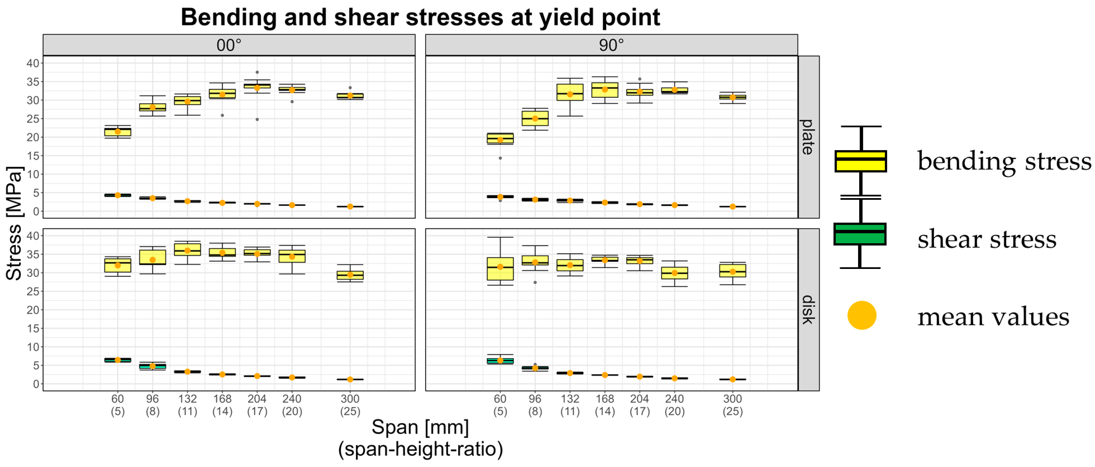
Figure 6 illustrates the determined bending and shear stresses at the yield point for all tested configurations. The calculation was carried out according to Equations A5 (bending) and A6 (shear) in the Appendix.
For plate loading, the determined bending stresses are initially low at small span-to-height ratios and tend to increase with higher ratios, approaching a limiting value that can be defined as the bending strength. The shear stresses, in contrast, are maximal at the smallest tested span-to-height ratio and decrease with increasing ratio. These trends indicate that at small span-to-height ratios, shear effects exert a greater influence on the load-bearing behavior. This becomes evident in the reduced bending stresses achieved compared to those at larger spans with lower shear influence.
It cannot be clearly established whether the specimens failed due to pure shear or pure bending, owing to the abrupt nature of failure. However, the results suggest that at small span-to-height ratios, shear failure occurs in the cross layers, whereas at larger ratios, failure is more likely caused by bending in the outer layers subjected to tensile stresses.
In disk loading, the determined bending stresses remain essentially constant across all span-to-height ratios. The shear stresses, as with plate loading, are maximal at the smallest ratio. No significant differences were observed between the 0° and 90° orientations in either plate or disk loading. Instead, the results suggest that all stress parameters across the tested configurations are on a comparable level, such that a single design strength value can be applied across all configurations. Table A7 in the Appendix summarizes the results of the material tests, listing mean values and standard deviations of the key parameters.
4. Conclusions
In the present study, a method for determining the bending and shear properties of wood-based materials, exemplified by WVC in the form of plywood, was introduced. The results of the material tests demonstrate the dependence of the global modulus of elasticity on the span-to-height ratio and on the orientation of the specimens with respect to the load and span directions. The regression analyses revealed that with the determined bending and shear moduli, the global modulus of elasticity can be reliably predicted for arbitrary geometries. In addition, bending and shear stresses at the proportional limit were reported.
The analyses suggest that a single strength value can be defined, independent of orientation and span-to-height ratio.
This establishes an initial foundation for the analytical dimensioning of wood-based structural components. The presented analyses are limited to the static loading case of three-point bending under monotonic loading until failure. Future investigations will need to address dynamic and long-term loading scenarios and derive corresponding parameters, thereby ensuring the analytical verification of component functionality over the intended service life.
Funding
The research project “Wood-based materials in mechanical engineering (HoMaba)”, on which this publication is based, was funded by the German Federal Ministry of Food and Agriculture (funding reference 22003818). The project was a joint project of the following research partners: TU of Munich, Fraunhofer Institute of Wood Research WKI, University of Technology Chemnitz, Eberswalde University of Sustainable Development, University of Göttingen and the Technical University of Applied Science Rosenheim.
Data Availability Statement
The original contributions presented in this study are included in the article. Further inquiries can be directed to the corresponding author.
Acknowledgments
The authors are grateful to all partners, who worked on the project and to the German Federal Ministry of Food and Agriculture for funding this project.
Conflicts of Interest
The authors declare no conflicts of interest.
Abbreviations
The following abbreviations are used in this manuscript:
| WVC | Wood Veneer Composite |
| EGlobal | global modulus of elasticity [MPa] |
| EBending | bending modulus [MPa] |
| G | shear modulus [MPa] |
| S | span length [mm] |
| A | cross-sectional area [mm2] |
| Iyy | moment of inertia [mm4] |
| κ | shear correction factor (for rectangular cross-sections κ=5/6) |
Appendix A
Appendix A.1

Table A1.
Formulas for Calculation in this paper.
| TIMOSHENKO Beam theorie | |
| A1.1 | |
| A1.2 | |
| A1.3 | |
| A1.4 | |
| Stresses | |
| A1.5 | |
| A1.6 | |
| wGlobal – total deformation [mm] ; wBiegung – deformation due to bending [mm] wSchub – deformation due to shear [mm] ; κ – shear correction factor F – applied load [N] ; S – span length [mm] ; Iyy – moment of inertia [mm4] ; A – cross-sectional area [mm²] ; EGlobal – global modulus of elasticity [MPa] ; EBending – bending modulus [MPa] ; G – shear modulus [MPa] b – cross-sectional width [mm] ; h – cross-sectional height [mm] ; Wy – section modulus [mm³] ; σBending – bending stress [MPa] ; τ – shear stress [MPa] ; MB – bending moment [Nmm] | |
Table A2.
Results of the material tests.
| orientation | span [mm] | span/height | Young‘ Modulus [MPa] | Bending Strength [MPa] | Shear Strength [MPa] |
| plate 00° | 60 | 5 | 2723 ± 201,4 | 21.5 ± 1.3 | 4.3 ± 0.26 |
| 96 | 8 | 4188 ± 62,4 | 28.08 ± 1.74 | 3.51 ± 0.22 | |
| 132 | 11 | 5363 ± 113,8 | 29.6 ± 1.76 | 2.7 ± 0.16 | |
| 168 | 14 | 5855 ± 144,9 | 31.48 ± 2.4 | 2.25 ± 0.17 | |
| 204 | 17 | 6457 ± 233,7 | 33.31 ± 3.34 | 1.97 ± 0.2 | |
| 240 | 20 | 6405 ± 178,9 | 32.69 ± 1.37 | 1.64 ± 0.07 | |
| 300 | 25 | 6691 ± 262,2 | 31.22 ± 1.1 | 1.25 ± 0.04 | |
| plate 90° | 60 | 5 | 2235 ± 185,0 | 19.22 ± 2.07 | 3.86 ± 0.42 |
| 96 | 8 | 3642 ± 199,4 | 25.01 ± 2.23 | 3.13 ± 0.28 | |
| 132 | 11 | 4623 ± 458,8 | 31.55 ± 3.46 | 2.86 ± 0.31 | |
| 168 | 14 | 5242 ± 295,9 | 32.84 ± 2.52 | 2.33 ± 0.18 | |
| 204 | 17 | 5562 ± 154,3 | 32.29 ± 1.84 | 1.9 ± 0.11 | |
| 240 | 20 | 5773 ± 163,7 | 32.77 ± 1.16 | 1.64 ± 0.06 | |
| 300 | 25 | 5703 ± 287,2 | 30.75 ± 0.94 | 1.23 ± 0.04 | |
| disk 00° | 60 | 5 | 5170 ± 196,6 | 31.98 ± 2.1 | 6.44 ± 0.42 |
| 96 | 8 | 5443 ± 451,0 | 38.27 ± 5.61 | 4.8 ± 0.71 | |
| 132 | 11 | 6509 ± 218,5 | 35.98 ± 2.05 | 3.29 ± 0.19 | |
| 168 | 14 | 6602 ± 348,6 | 35.4 ± 1.69 | 2.54 ± 0.12 | |
| 204 | 17 | 6702 ± 372,3 | 35.68 ± 2.31 | 2.11 ± 0.14 | |
| 240 | 20 | 6814 ± 345,1 | 34.33 ± 2.42 | 1.72 ± 0.12 | |
| 300 | 25 | 6026 ± 362,6 | 29.46 ± 1.59 | 1.18 ± 0.06 | |
| disk 90° | 60 | 5 | 4642 ± 236,3 | 31.59 ± 4.16 | 6.32 ± 0.83 |
| 96 | 8 | 4826 ± 271,1 | 33.72 ± 3.95 | 4.22 ± 0.5 | |
| 132 | 11 | 5732 ± 229,7 | 32.06 ± 2.03 | 2.91 ± 0.18 | |
| 168 | 14 | 5684 ± 179,5 | 33.39 ± 0.99 | 2.38 ± 0.07 | |
| 204 | 17 | 5991 ± 163,1 | 33.18 ± 1.36 | 1.95 ± 0.08 | |
| 240 | 20 | 5659 ± 256,7 | 29.94 ± 2.25 | 1.49 ± 0.11 | |
| 300 | 25 | 5872 ± 264,8 | 30.28 ± 2.14 | 1.21 ± 0.08 |
References
- Sikkema, R.; Dallemand, J.F.; Matos, C.T.; van der Velde, M.; San-Miguel-Ayanz, J. How can the ambitious goals for the EU’s future bioeconomy be supported by sustainable and efficient wood sourcing practices? Scand. J. For. Res. 2017, 32, 551–558. [CrossRef]
- Brownell, H.; Iliev, B.E.; Bentsen, N.S. How much wood do we use and how do we use it? Estimating Danish wood flows, circularity, and cascading using national material flow accounts. J. Clean. Prod. 2023, 423. [CrossRef]
- Food and Agriculture Organization of the United Nations: The State of the World’s Forests 2024. 08-2025.
- Ross, R. J.; Richter, K. Part D General Aspects and Concepts in Wood Utilization. In Springer Handbook of Wood Science and Technology. Niemz, P.; Teischinger, A.; Sandberg, D. Springer Nature Switzerland, 2023, pp. 1786 – 1974.
- Ramage, M.H.; Burridge, H.; Busse-Wicher, M.; Fereday, G.; Reynolds, T.; Shah, D.U.; Wu, G.; Yu, L.; Fleming, P.; Densley-Tingley, D.; et al. The wood from the trees: The use of timber in construction. Renew. Sustain. Energy Rev. 2017, 68 Pt 1, 333–359.
- Mair-Bauernfeind, C.; Zimek, M.; Asada, R.; Bauernfeind, D.; Baumgartner, R.J.; Stern, T. Prospective sustainability assessment: the case of wood in automotive applications. Int. J. Life Cycle Assess. 2020, 25, 2027–2049. [CrossRef]
- Guenther, R.; Tajmer, M.; Bach, C. Wood and Wood-Based Materials in Space Applications – A Literature Review of Use Cases, Challenges and Potential. Aerospace 2024, 11(11), pp. 910.
- ligenium: Innovative Materialtransportlösungen für Maschinenbau, Produktion und Logistik. 08-2025.
- Holz im Maschinen- und Anlagenbau: Forschungsgruppe Anwendung erneuerbarer Werkstoffe der TU Chemnitz. 08-2025.
- NEQ: Holzbaukran. 08-2025.
- Ashby, M. F. Materials selection in mechanical design. 3rd ed.; Butterworth-Heinemann, Oxford, 2005. pp. 3-4, 37-39 . ISBN: 0-7506-4357-9.
- Baensch, F. Damage evolution in wood and layered wood composites monitored in situ by acoustic emission, digital image correlation and synchrotron based tomographic microscopy, ETH-Zürich, Zürich, 2015.
- Keylwerth, R. Die anisotrope Elastizität des Holzes und der Lagenhölzer. VDI-Forschungsheft 430, 1951 (Ausgabe B Band 17).
- Forschungsgruppe Anwendung erneuerbarer Werkstoffe – Projekte. 08-2025.
- Molotnikov, V.; Molotnikov, A. Theoretical and Applied Mechanics. Springer Nature Switzerland, 2023. ISBN: 978-3-031-09312-8.
- Li, M. Evaluating rolling shear strength properties of cross-laminated timber by short-span bending tests and modified planar shear tests. J. Wood Sci. 2017, 63, 331–337. [CrossRef]
- Wang, T.; Wang, Y.; Crocetti, R.; Wålinder, M. In-plane mechanical properties of birch plywood. Constr. Build. Mater. 2022, 340. [CrossRef]
- Wang, T.; Huang, Q.; Wang, Z.; Gong, M. Rolling shear failure of CLT transverse layer: AE characterization of damage mechanisms under different test methods. Constr. Build. Mater. 2024, 440. [CrossRef]
- Zhang, L.-P.; Xie, Q.-F.; Han, Y.-G.; Sui, Y.; Wu, Y.-J.; Xue, J.-Y.; Wang, Y.-C. Experimental study on the mechanical properties of wood subjected to combined perpendicular-to-grain normal and rolling shear loads. Constr. Build. Mater. 2024, 449. [CrossRef]
- Bader, T. K.; Ormarsson, S. Chapter 10 Modeling the mechanical Behavior of Wood Materials and Timber Structures. In Wood Science and Technology. Niemz, P.; Teischinger, A.; Sandberg, D. Springer Nature Switzerland, 2023, pp. 536.
- EN 408:2012; Timber Structures—Structural Timber and Glued Laminated Timber—Determination of Some Physical and Mechanical Properties (Includes Amendment A1:2012). European Comitee for Standardization: Brussels, Belgium, 2012.
- EN 789:2005; Timber structures – Test methods – Determination of mechanical properties of wood based panels. European Comitee for Standardization: Brussels, Belgium, 2005.
- EN 310:1993; Wood-Based Panels—Determination of Modulus of Elasticity in Bending and of Bending Strength. European Comitee for Standardization: Brussels, Belgium, 1993.
- Engelhardt, M.; Khaloian Sarnaghi, A.; Buchelt, B.; Krüger, R.; Schulz, T.; Gecks, J.; Kluge, P. et al. Holzbasierte Werkstoffe im Maschinenbau (HoMaba) - Berechnungskonzepte, Kennwertanforderungen, Kennwertermittlung (Wood-Based Materials in Mechanical Engineering - Calculation Concepts, Parameter Requirements, Parameter Determination); Technische Informationsbibliothek (TIB): Hanover, Germany, 2022.
- Meynerts, P. Mechanische Eigenschaften von Holzwerkstoffen. Datenbank. 08-2025.
- Krüger, R.; Buchelt, B.; Wagenführ, A. Method for determination of beech veneer behavior under compressive load using the short-span compression test. Wood Sci. Technol. 2023, 57, 1125–1138. [CrossRef]
- Buchelt, B.; Wagenführ, A.; Dietzel, A.; Raßbach, H. Quantification of cracks and cross-section weakening in sliced veneers. Eur. J. Wood Wood Prod. 2017, 76, 381–384. [CrossRef]
- Kluge, P.; Eichhorn, S. Calculation Concept for Wood-Based Components in Mechanical Engineering. Adv. Eng. Mater. 2023, 25. [CrossRef]
- Kluge, P. Dimensioning and calculation concepts for statically stressed components made of wood veneer composite materials for use in mechanical engineering. PHD, TU Chemnitz, 2024.
- Krüger, R.; Buchelt, B.; Zauer, M.; Wagenführ, A. Veneer Composites for Structural Applications—Mechanical Parameters as Basis for Design. Forests 2025, 16, 617. [CrossRef]
- Krüger, R. Investigations on rotary-cut veneer of beech wood for the application of veneer-based materials in mechanical engineering. PHD, TU Dresden, 2022.
- EN 323:1993; Wood-based panels – Determination of density. European Comitee for Standardization: Brussels, Belgium, 2023.
- EN 322:1993; Wood-based panels – Determination of moisture content. European Comitee for Standardization: Brussels, Belgium, 2023.
- EN 1995-1-1:2023 - 10-Entwurf; Eurocode 5 – Design of timber structures – Part 1-1: General rules and rules for buildings. European Comitee for Standardization: Brussels, Belgium, 2023.
- Spura, C. Technische Mechanik 2. Elastostatik: Nach fest kommt ab. 1. Auflage, Springer Vieweg, Wiesbaden, pp. 223 - 266. ISBN: 978-3-658-19978-4.
Figure 1.
Ashby-graphics; a) strength/Density; b) Young’s modulus/Density.
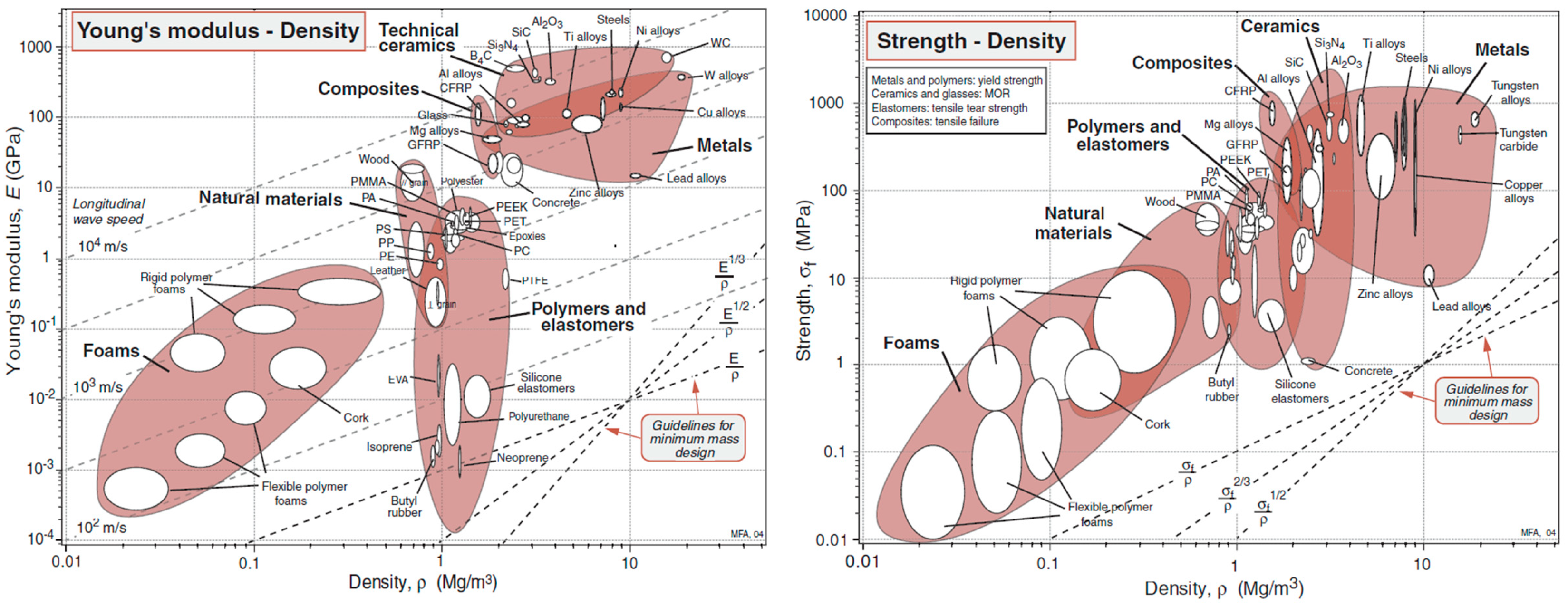
Figure 2.
Overview of the experimental setup; left: tested configurations according to EN 1995-1 [24]; top right: test setup; bottom right: tested span-to-height ratios.
Figure 2.
Overview of the experimental setup; left: tested configurations according to EN 1995-1 [24]; top right: test setup; bottom right: tested span-to-height ratios.
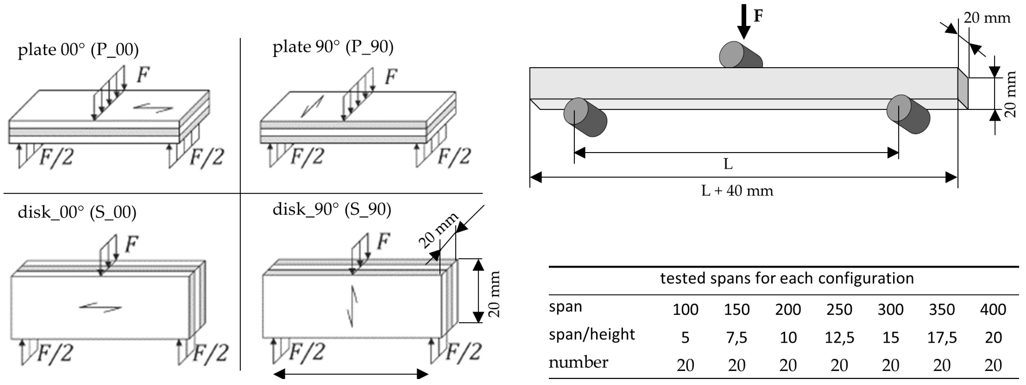
Figure 3.
Exemplary force–displacement curve with the key parameters used for property determination.
Figure 3.
Exemplary force–displacement curve with the key parameters used for property determination.
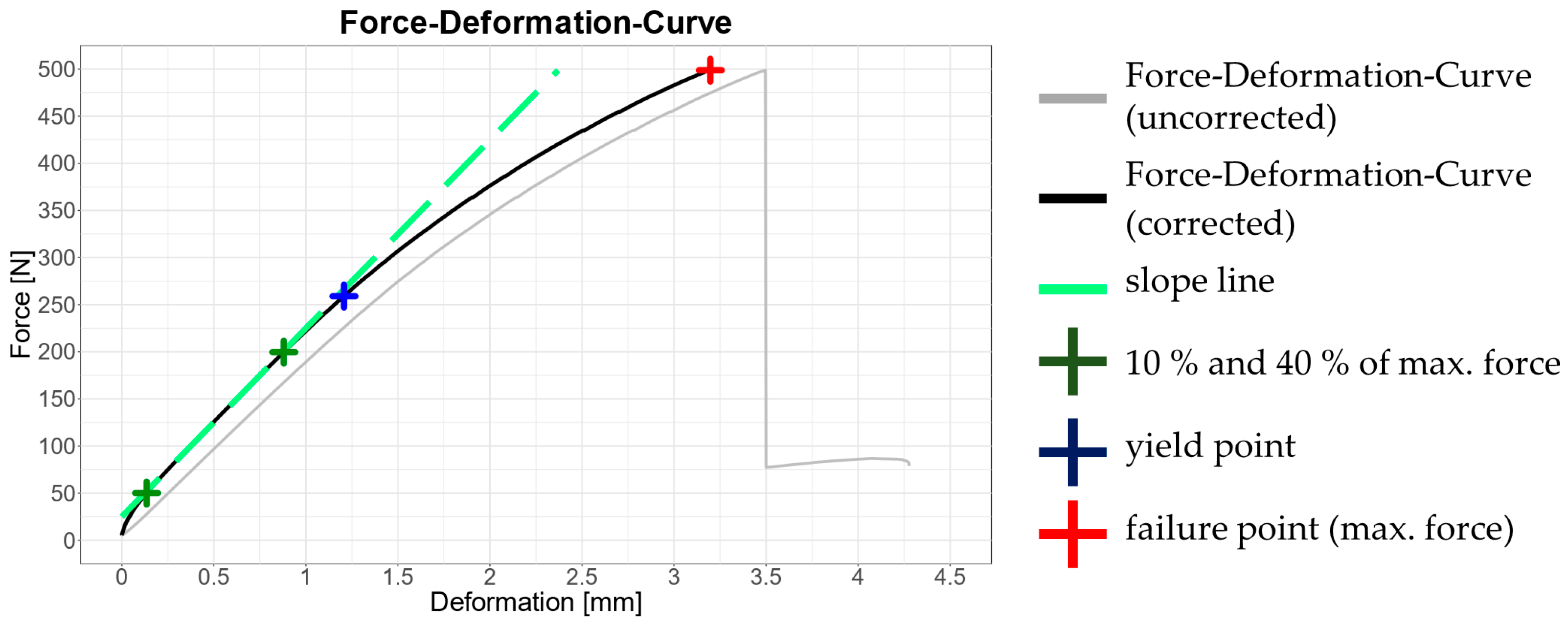
Figure 4.
Global moduli of elasticity and results of the nonlinear regression.
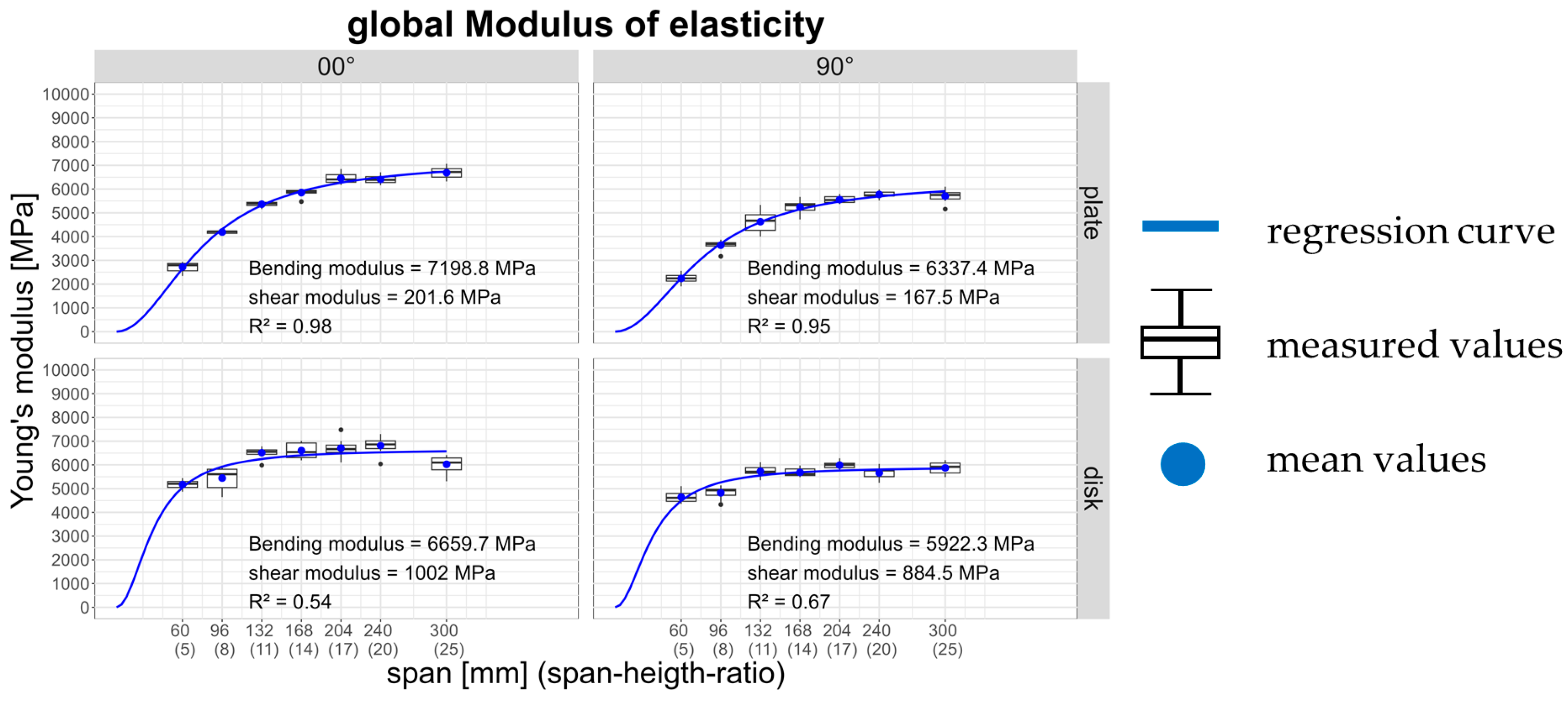
Figure 5.
Stress scenarios in plate and disk loading [29].
Figure 5.
Stress scenarios in plate and disk loading [29].
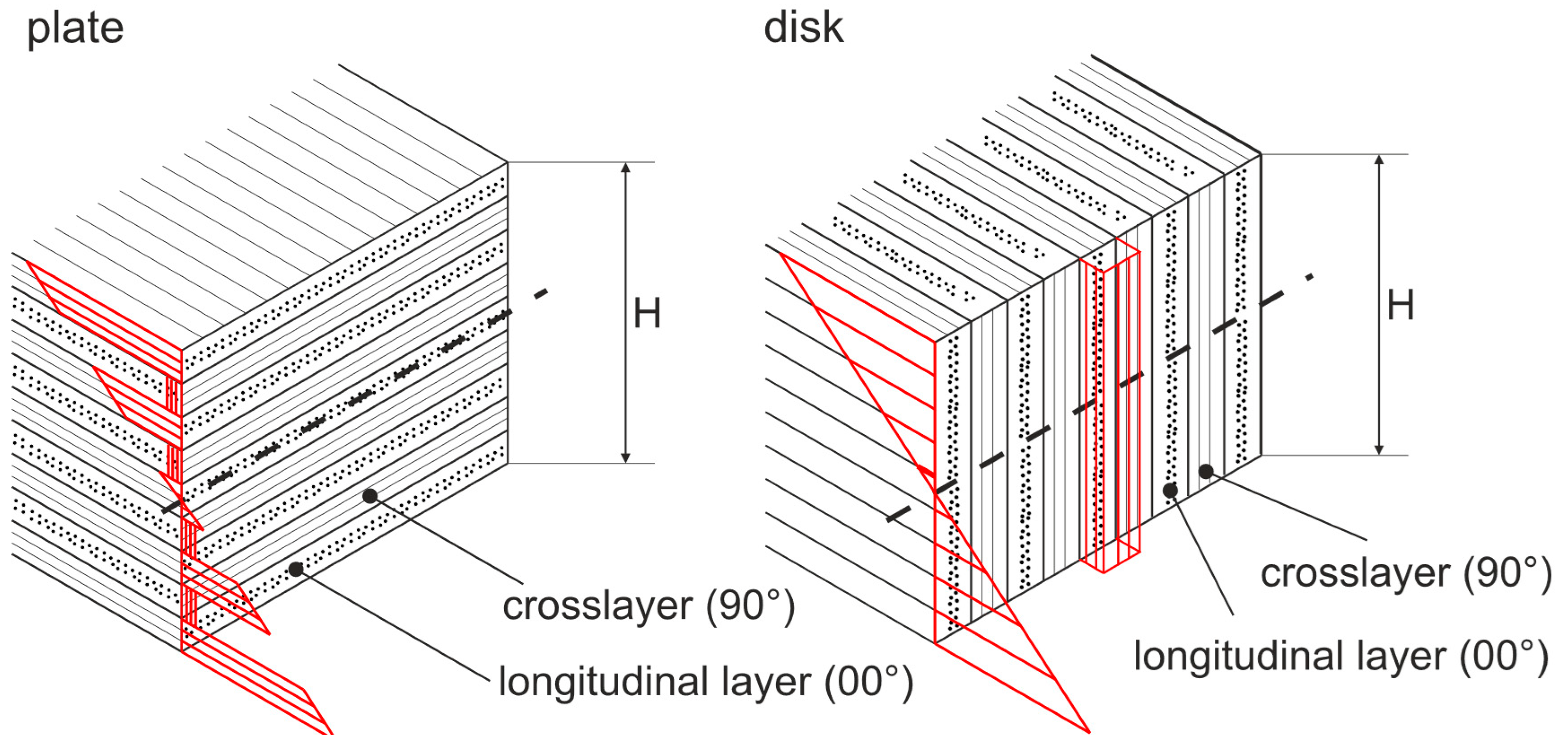
Figure 6.
Bending and shear stresses at the yield point.
| material | No. of Layers | Layer Thickness | Thickness | Density | Moisture Content |
| Birch plywood | 9 | 1,33 mm | 12 mm | 650 kg m-3 | 8,78 % |
Disclaimer/Publisher’s Note: The statements, opinions and data contained in all publications are solely those of the individual author(s) and contributor(s) and not of MDPI and/or the editor(s). MDPI and/or the editor(s) disclaim responsibility for any injury to people or property resulting from any ideas, methods, instructions or products referred to in the content. |
© 2025 by the authors. Licensee MDPI, Basel, Switzerland. This article is an open access article distributed under the terms and conditions of the Creative Commons Attribution (CC BY) license (http://creativecommons.org/licenses/by/4.0/).
Copyright: This open access article is published under a Creative Commons CC BY 4.0 license, which permit the free download, distribution, and reuse, provided that the author and preprint are cited in any reuse.


