Submitted:
02 September 2025
Posted:
05 September 2025
Read the latest preprint version here
Abstract
Environmental microorganisms are a rich yet underused source of bioactive chemistry, but many remain uncultivated and numerous biosynthetic gene clusters fall silent ex situ. NP-TRAP (Natural Product–Targeted Recovery and Adsorption Platform) is introduced here as a modular concept that unites in situ cultivation with adjacent, retrieval-ready metabolite capture. The device architecture couples cell-excluding 0.2-μm microfiltration interfaces with optional, gently duty-cycled vacuum to bias metabolite flow in one direction while preserving near-ambient conditions at the culture layer. A practical specification is outlined: probabilistic single-cell loading to favor clonal growth (including slow growers), low-nutrient gels and matrix-matched osmolarity, inert structural materials and corrosion-aware fasteners, elastomeric duckbill check-valving with redundant non-return protection, two field-friendly filling workflows (fill-then-seal or micro-port injection), and a simplified two-layer variant when affinity or imprinted membranes are used to seal culture wells. Positioned against iChip, Small Molecule In Situ Resin Capture (SMIRC), and the Microbial Containment Device (MCD), NP-TRAP aims to maintain producer–metabolite traceability while remaining simple and stackable for exploratory deployments. A compact bench plan is also suggested—airtightness checks, adsorption/desorption across a polarity range, valve unidirectionality, oxygen stability under cycling, a clip-on prefilter to manage fouling, and monoclonality validation—to guide early pilots. Empirical testing has not yet been performed; the concept and specification are offered to motivate laboratory and environmental trials as resources become available.
Keywords:
in situ cultivation
; microbial metabolites
; natural product discovery
; honeycomb device
; microfiltration membrane
; metabolite adsorption
; environmental microbiology
; vacuum-assisted retrieval
Introduction
Only a small fraction of microbial chemodiversity has been accessed with conventional cultivation, as many taxa resist ex situ growth and numerous biosynthetic gene clusters are conditionally expressed or remain silent [1,2,3,4,5,6]. In situ tools such as iChip and diffusion chambers broaden cultivability by permitting environmental exchange across cell-excluding membranes [1,2,3,9,10,11]. By contrast, Small Molecule In Situ Resin Capture (SMIRC) follows a compound-first strategy that decouples metabolites from specific producers [12], while the Microbial Containment Device (MCD) enables confined in situ studies without integrated metabolite retrieval [13]. Related patent work has also explored diffusion-based devices for detecting metabolites under natural conditions [14]. NP-TRAP is intended to bridge these approaches by bringing together compartmental cultivation, selective capture (resins or affinity/imprinted membranes), and mild, suggested duty-cycled suction to promote unidirectional extraction while maintaining near-ambient gas exchange at the culture layer. Here, “0.2-µm microfiltration membrane” denotes cell-exclusion barriers; “selectively permeable/affinity membrane” denotes materials with molecular recognition or molecular-weight cutoffs [15,16]. Against the broader backdrop of sustainable antibiotic discovery and exploration of under-sampled environments, this integration targets both cultivability and chemical readout [7,8,17,18,19].
Methods
Device Architecture and Functional Design
The baseline module uses three honeycomb layers in a 12 × 12 cm footprint. Fifty-six hexagonal wells (17 mm across flats, 4 mm depth) provide approximately 0.75 mL working volume each, with peripheral through-holes for alignment and stacking. Adjacent layers are separated by 0.2-µm hydrophilic microfiltration membranes of polytetrafluoroethylene (PTFE), polyethersulfone (PES), or polyvinylidene fluoride (PVDF) with 80–150 µm thickness. Where finer selectivity is needed, affinity or molecularly imprinted membranes can replace or complement resin capture without altering the overall stack [15,16].
Metabolites are captured in a dedicated layer containing 10–25 mg of HP-20/Amberlite XAD-type resin per well (up to 40 mg when yield permits), spanning a broad polarity range [20,21,22]. Below each capture well, a silicone duckbill check-valve (elastomeric, not a filter membrane) sits in a shallow conical seat (slit 2.0–2.5 mm, wall 0.25–0.35 mm, opening angle 8–12°, cracking pressure 0.2–0.5 kPa), favoring unidirectional flow toward a lateral vacuum manifold. An inline non-return valve at the outlet adds redundancy.
If negative pressure is employed, downstream placement relative to the capture layer is suggested, limited to a pressure differential (ΔP) of approximately 5–10 mbar (0.5–1.0 kPa). Oil-free diaphragm pumps (for example, KNF Neuberger) are suggested at 0.1–1.0 L·min⁻¹ with programmable duty-cycling—illustratively 1–5 minutes ON per 30–60 minutes OFF—to support retrieval while keeping the culture interface near ambient partial pressures of oxygen.
Materials are specified for chemical inertness and field robustness: poly(ether ether ketone) (PEEK), polycarbonate (PC), and polypropylene (PP) for structure; PEEK or titanium grade 2 (Ti-2) for fasteners (with stainless steel 316 [SS-316] only if passivated and kept away from high-salinity or acidic environments); and expanded polytetrafluoroethylene (ePTFE) or medical-grade silicone gaskets (0.5–1.0 mm) under torque-controlled compression. Adhesive-backed or thermally laminated membranes can improve uniformity and handling.
Two-Layer Simplified Variant
When each culture well is sealed at the top by an imprinted/affinity membrane, the open top layer may be omitted. The resulting stack—culture layer (bottom-sealed by a 0.2-µm microfiltration membrane) → capture layer (top-sealed by an affinity membrane) → valve-cap—preserves exchange laterally and/or through the upper affinity membrane while reducing part count. Elimination of the open top layer is contingent on reliable per-well sealing, to be verified by the suggested benchtop checks below.
Device Loading and Environmental Deployment
To favor isolation, NP-TRAP employs limiting-dilution loading under a Poisson regime with λ ≈ 0.1–0.2 cells·well⁻¹, yielding P(≥2) < 2%. For 0.5 mL fills, a titer of 0.2–0.4 cells·mL⁻¹ is targeted and verified by droplet plating. Physical compartmentalization maintains clonal enrichment during extended in situ incubation. Slow-growing or low-abundance taxa are supported by low-nutrient gellan/agar (1.5–2%), matrix-matched osmolarity, and longer deployments (21–56 days), followed by single-well subculture and standard taxonomic workflows (morphology plus 16S rRNA gene sequencing [16S], internal transcribed spacer [ITS], and whole-genome sequencing [WGS]) [1,2,3,9,10,11].
When both faces of a culture well are membrane-bound, two practical fills are used. Fill-then-seal: the bottom membrane is sealed; warm soft-gel medium (40–45 °C) plus inoculum is dispensed (0.5–0.75 mL), allowed to gel, and the top membrane is laminated by low-temperature pressure lamination or a pressure-sensitive adhesive (PSA) membrane using a rigid stencil. Micro-port injection: both membranes are pre-laminated; a 100–200 µm port is laser-punched and medium is injected through a 30–32 G needle; the puncture is sealed with an ultraviolet (UV)-curable biocompatible dot or PSA micro-patch. Suggested acceptance: no dye leakage or mass loss greater than 1% under ±20 mbar for 10 minutes; visual integrity at 40–45 °C.
Reproducibility Package
Per-well dimensions: across-flats 17 ± 0.2 mm, depth 4.0 ± 0.1 mm, wall 2.0 ± 0.1 mm, seat chamfer 30° × 0.5 mm.
Membranes: 0.2 µm hydrophilic PTFE/PES/PVDF (80–150 µm), adhesive-backed or thermally laminated.
Resins: HP-20/XAD-18; 10–25 mg per well (up to 40 mg).
Valves: silicone duckbill; slit 2.0–2.5 mm, wall 0.25–0.35 mm, cracking 0.2–0.5 kPa, seat outer diameter (OD) 4.0–4.5 mm.
Pump and control: suggested oil-free diaphragm pump; ΔP 5–10 mbar; duty 1–5 min·h⁻¹; outlet non-return valve.
Materials: structural PEEK/PC/PP; fasteners PEEK/Ti-2; gaskets ePTFE/silicone 0.5–1.0 mm.
Suggested Bench Pre-Validation
A compact benchtop verification set is outlined to make the concept actionable once a basic lab setup is available. Airtightness and sealing: pressure-decay at +20 mbar and –10 mbar for 10 minutes with less than 5% ΔP as a practical target. Valve unidirectionality: bubble-point and dye-backflow per well with no reverse flow at +0.5 kPa; confirm redundancy via the inline non-return valve. Resin adsorption/desorption: spike extracts across the octanol/water partition coefficient (logP) range −1 to 5; compare static versus duty-cycled flow; elute with methanol/ethyl acetate; use liquid chromatography–mass spectrometry (LC-MS) recovery to tune resin mass [20,21,22]. Vacuum perturbation: monitor partial pressure of oxygen (pO₂) at the culture interface with a fiber-optic micro-sensor during cycling; aim for change in partial pressure of oxygen (ΔpO₂) less than 5% of ambient per cycle. Membrane sealing of culture holes: dye penetration and leak-rate checks under ±20 mbar; target no visible ingress/egress and less than 1% mass transfer in 10 minutes. Fouling evaluation (contingent): challenge with particles under 63 µm to induce about 30% flow drop, add a clip-on 5–10 µm polyamide/PP mesh prefilter, and verify at least 80% flow recovery without backflush. Monoclonality verification: seed a tracer strain at λ = 0.1/0.2/0.3; plate-out to estimate P(≥2) versus Poisson predictions and refine standard operating procedures (SOPs).
Figure 1.
Illustrative exploded schematic of the NP-TRAP device highlighting its main conceptual components. The top layer allows passive influx of nutrients and substrate-derived molecules from the environment and remains unsealed by membrane. The second layer contains 56 hexagonal cultivation chambers arranged in a honeycomb pattern and is separated from the top layer by a 0.2 µm microfiltration (cell-excluding) membrane, enabling molecular diffusion while excluding cells. The third layer, designed for metabolite capture, is also separated by a 0.2 µm microfiltration membrane and houses adsorbent resins or compound-selective membranes. A unidirectional diaphragm layer with duckbill-type silicone check-valves, beneath an additional 0.2 µm microfiltration membrane, prevents reflux. All layers are aligned through peripheral orifices and secured using stainless steel rods and nuts. The bottom cap includes a lateral vacuum outlet fitted with a non-return valve for mild suction.
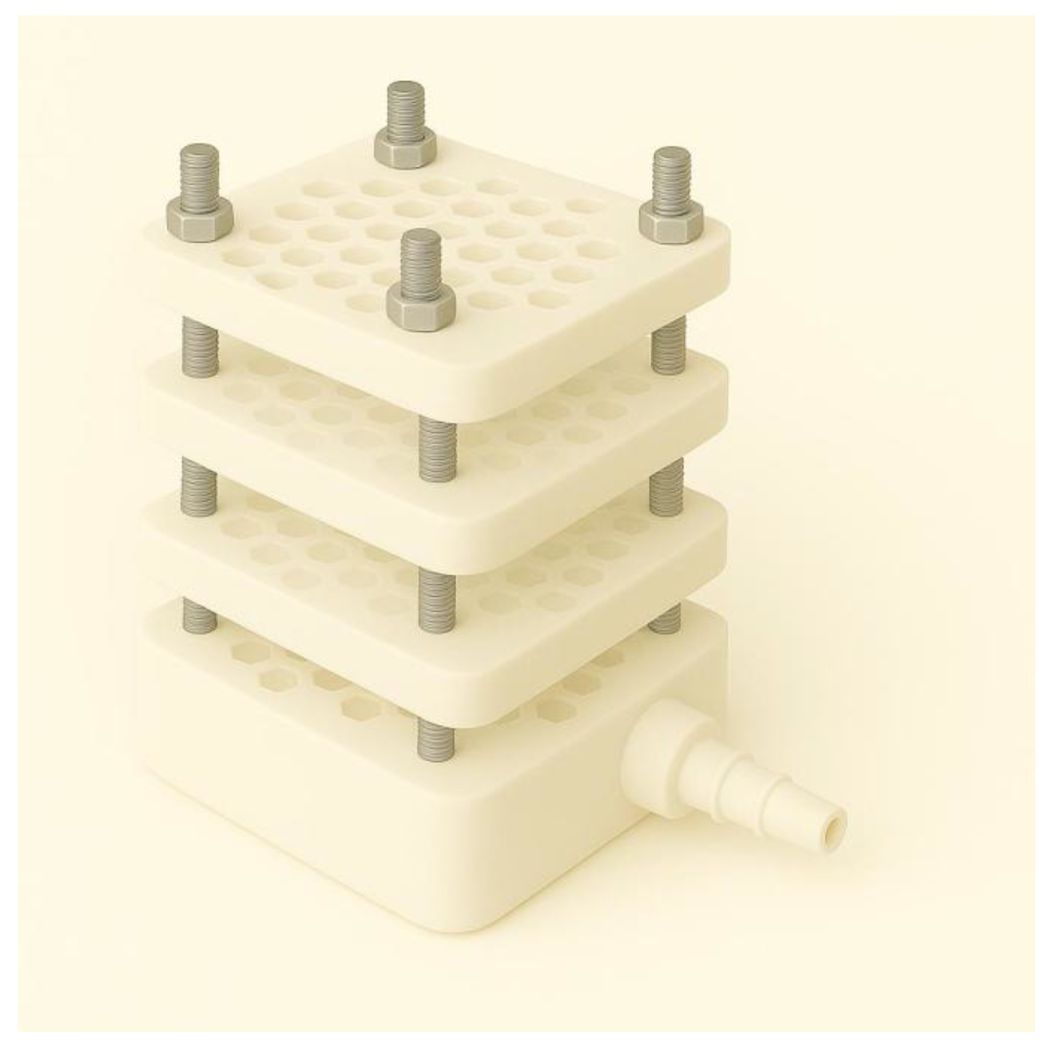
Figure 2.
Middle honeycomb-patterned layer of the NP-TRAP device (12 × 12 cm). This component contains 56 uniform hexagonal through-holes (each ~17 mm across and 4 mm deep), with an internal volume of approximately 0.75 mL per well. These orifices are arranged in a honeycomb pattern and support either microbial cultivation or metabolite capture, accommodating solid or semisolid growth media, adsorbent resins, or imprinted membranes. The hexagonal geometry improves surface-to-volume ratio, molecular diffusion efficiency, and spatial compartmentalization. Peripheral alignment holes facilitate precise stacking and sealing of layers.
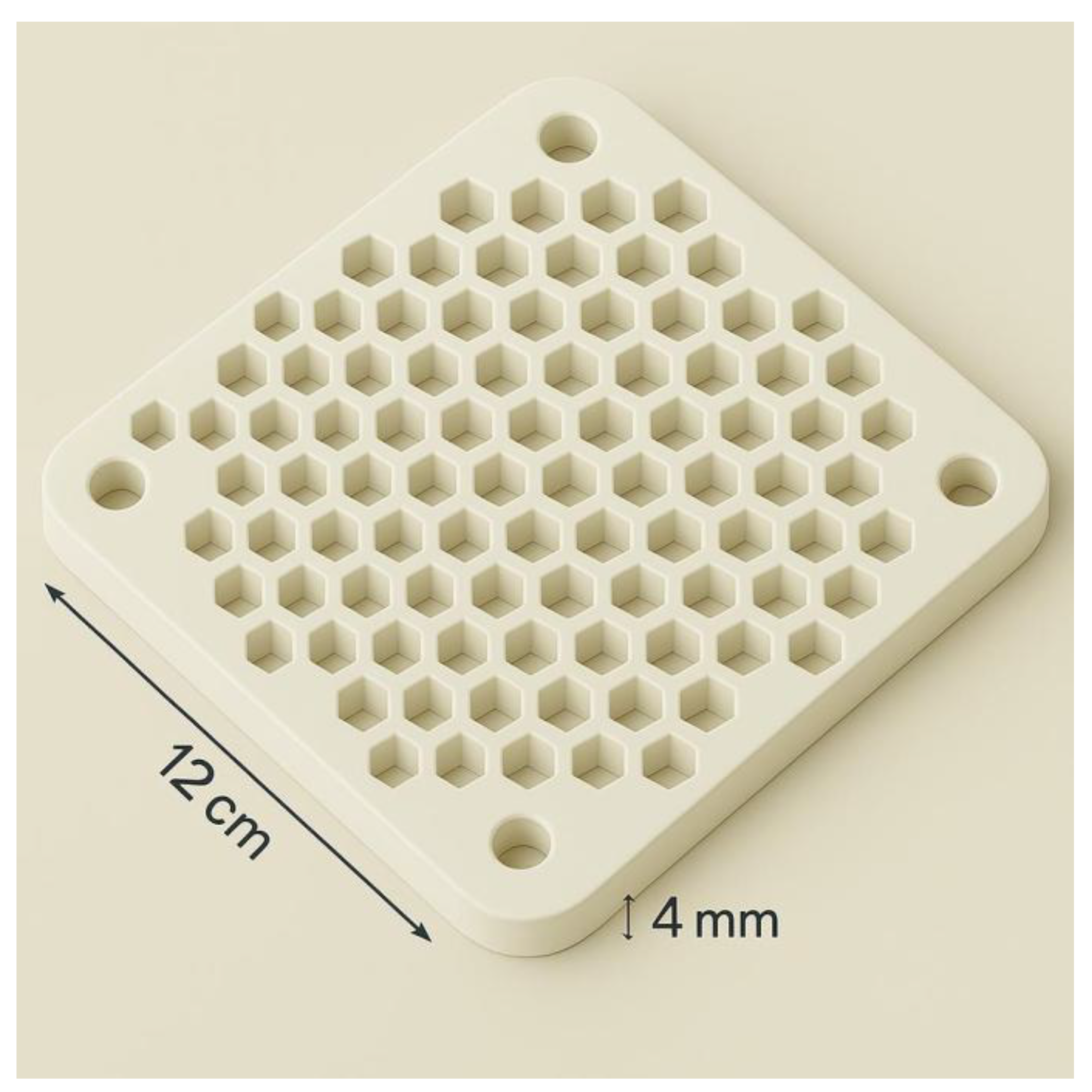
Figure 3.
Diaphragm interface integrated into the top of the bottom cap. Each hexagonal compartment is fitted with a central duckbill-type silicone valve to ensure unidirectional flow and prevent backflow or cross-contamination. This configuration enables passive or suggested mild vacuum-assisted metabolite transport from the cultivation chambers into the capture layer.
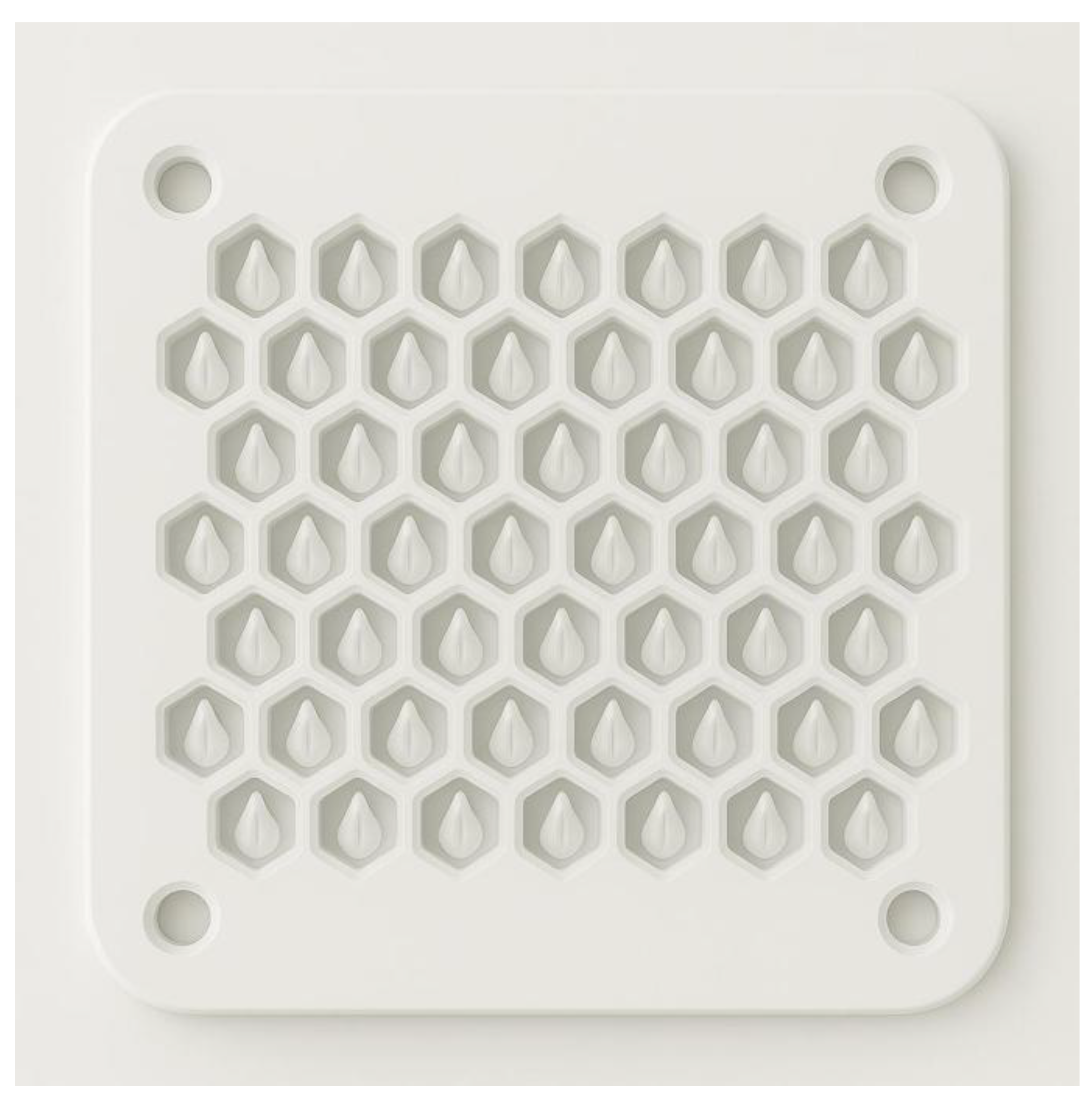
Figure 4.
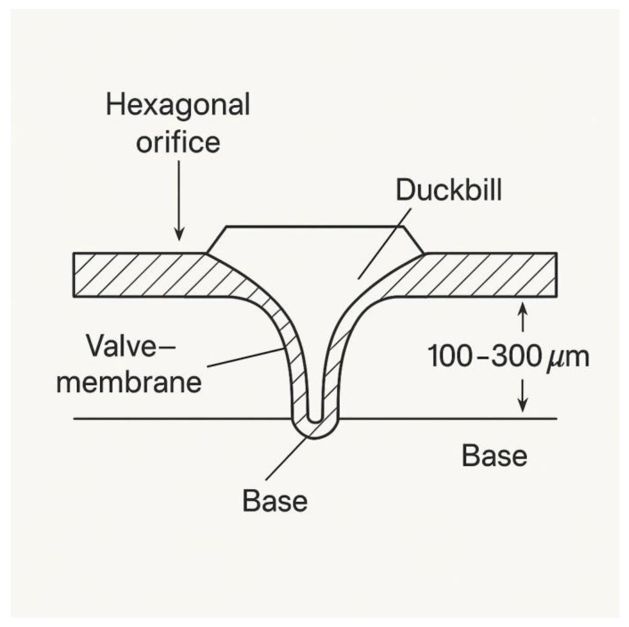
Cross-sectional schematic of a duckbill silicone valve integrated into each hexagonal orifice on the upper surface of the vacuum outlet cap of the NP-TRAP device. This valve layer is positioned beneath the microfiltration membrane adhered to the bottom of the metabolite capture chamber. The elastomeric element (~100–300 µm thick) is molded into a unidirectional duckbill shape, allowing metabolite flow toward the bottom cap and connected vacuum line, while preventing backflow into the capture zone.
Figure 4.
Cross-sectional schematic of a duckbill silicone valve integrated into each hexagonal orifice on the upper surface of the vacuum outlet cap of the NP-TRAP device. This valve layer is positioned beneath the microfiltration membrane adhered to the bottom of the metabolite capture chamber. The elastomeric element (~100–300 µm thick) is molded into a unidirectional duckbill shape, allowing metabolite flow toward the bottom cap and connected vacuum line, while preventing backflow into the capture zone.
Discussion
Potential membrane clogging is handled operationally to keep the device simple under environmental use. Two fouling modes are anticipated—biofilm accrual and particulate loading—and the clip-on 5–10 µm prefilter at the environmental intake is suggested for quick swaps as pressure-drop increases; a single stress step can demonstrate at least 80% flow recovery after a swap. Hydrophilic, low-protein-binding microfiltration films are preferred; OFF intervals in duty-cycled operation reduce continuous loading. Where matrices are highly particulate, a spare prefiltered face or a standby bottom-cap can be exchanged without disturbing cultivation.
On single-cell occupancy and isolation, a limiting-dilution regime (λ ≈ 0.1–0.2 cells·well⁻¹) biases for monoclonality (P(≥2) < 2%). Spatial compartmentalization prevents mixing during extended in situ growth, so continuous cultivation in-device functions as the isolation step. After incubation, each well is subcultured individually, and a tracer-strain check (λ = 0.1/0.2/0.3) with plate-outs can empirically validate occupancy before field trials—especially relevant to slow-growing or low-abundance taxa supported by low-nutrient, matrix-matched gels and longer deployments (21–56 days) [1,2,3,9,10,11].
For vacuum-assisted retrieval, risks to oxygen partial pressure and osmotic/pressure balance are controlled by keeping ΔP ≤ 10 mbar, applying suction intermittently, and placing the pump downstream from the capture layer to keep the culture interface near ambient composition. A pO₂ micro-sensor can verify ΔpO₂ under 5% across a cycle. Gel matrices buffer transients; ramped start-up mitigates pressure shock. Microaerophiles can be accommodated by overlays or by choosing deployment depths with lower oxygen.
Material compatibility is considered to avoid growth inhibition: structural PEEK/PC/PP are prioritized; PEEK/Ti-2 fasteners avoid corrosion, while SS-316 (if used) should be passivated and avoided in brine/acid settings. Simple extractables control (methanol/water rinses) is suggested pre-deployment; where feasible, eluate spot-checks by LC-MS can flag leachables. In parallel, adjacent capture followed by liquid chromatography–tandem mass spectrometry (LC-MS/MS) profiling enables dereplication against known metabolite libraries and prioritization of novel features, with molecular networking providing a practical pathway for feature grouping and identification [19,23].
In the broader context, NP-TRAP aims to combine the cultivability expansion of iChip/diffusion chambers with the compound-first reach of SMIRC, while maintaining producer–metabolite traceability through adjacent capture and gentle, suggested suction in a modular stack [1,2,3,9,10,11,12,13,14,15,16]. The approach is framed against the need for sustainable, cost-conscious discovery under real-world constraints [7,8,17,18].
The concept’s performance must still be established across habitats; resin selectivity and deployment duration will likely require site-specific SOPs. Treating anti-fouling as an operational contingency trades plumbing complexity for fast consumable swaps, which is practical but may increase consumable use in highly particulate matrices. The suggested benchtop checks (airtightness, valve tests, adsorption/desorption curves, oxygen stability, membrane sealing, fouling-recovery, and Poisson validation) are intended to surface constraints early and guide iterative refinement ahead of field deployments.

Table 1.
Comparative features of microbial in situ cultivation platforms.
| Feature | iChip | SMIRC | MCD | NP-TRAP |
|---|---|---|---|---|
| In situ cultivation | ✓ | ✗ | ✓ | ✓ |
| Metabolite adsorption | ✗ | ✓ | ✗ | ✓ |
| Vacuum-assisted extraction | ✗ | ✗ | ✗ | ✓ |
| Expandable modularity | ✗ | ✗ | ✗ | ✓ |
| Strain-level traceability | ✗ | ✗ | ✓ | ✓* |
* Traceability depends on analytical validation.
Conclusions
NP-TRAP is presented as a concept that brings together in situ compartmental cultivation, adjacent selective capture, and directionally assisted retrieval in a single, buildable format. By treating anti-fouling as a contingency rather than a built-in subsystem, the idea aims to remain simple, serviceable, and field-oriented while retaining a mitigation path when particulate loads are high. With the specification set and bench pre-validation described here, the concept may help motivate laboratory pilots and environmental trials that explore connections between strain identity and metabolite profiles across diverse habitats. To the author’s knowledge, there is currently no single platform that integrates in situ cultivation with on-device, retrieval-ready metabolite capture in a way that preserves strain-level traceability while remaining relatively low-cost. NP-TRAP is offered as a step in that direction—deliberately simple, likely to reveal practical challenges, and intended to catalyze iterative improvements toward robust, affordable, and field-practical devices.
Scope Statement
This article presents the Natural Product–Targeted Recovery and Adsorption Platform (NP-TRAP), a conceptual, modular platform that integrates in situ microbial cultivation with directional capture and retrieval of small molecules. The work details architecture, materials, operating envelopes, and suggested bench checks; positions NP-TRAP relative to iChip, Small Molecule In Situ Resin Capture (SMIRC), and the Microbial Containment Device (MCD); and outlines how field-deployable, scalable use under near-natural conditions could connect strain identity to metabolite profiles.
Credit Author Statement
Maxwel Adriano Abegg: Conceptualization, Investigation, Methodology, Writing – original draft, Writing – review and editing.
AI Use Declaration
No artificial intelligence (AI) systems are authors. Generative AI (ChatGPT) was used for language polishing and figure drafting under the author’s explicit technical instructions. Figures artwork involved AI assistance.
Funding
No external funding was received for this work.
Data Availability Statement
This article presents a conceptual device. No datasets were generated or analyzed. The technical concept may be subject to intellectual property protection; requests for clarification should be directed to maxabegg@gmail.com.
Conflict of Interest
The authors declare that the research was conducted in the absence of any commercial or financial relationships that could be construed as a potential conflict of interest.
References
- Nichols D, Cahoon N, Trakhtenberg EM, et al. Use of ichip for high-throughput in situ cultivation of “uncultivable” microbial species. Appl Environ Microbiol. 2010;76(8):2445–2450. [CrossRef]
- Kaeberlein T, Lewis K, Epstein SS. Isolating “uncultivable” microorganisms in pure culture in a simulated natural environment. Science. 2002;296(5570):1127–1129. [CrossRef]
- Alain K, Querellou J. Cultivating the uncultured: limits, advances and future challenges. Extremophiles. 2009;13(4):583–594. [CrossRef]
- Rutledge PJ, Challis GL. Discovery of microbial natural products by activation of silent biosynthetic gene clusters. Nat Rev Microbiol. 2015;13(8):509–523. [CrossRef]
- Milshteyn A, Schneider JS, Brady SF. Mining the metabiome: identifying novel natural products from microbial communities. Chem Biol. 2014;21(9):1211–1223. [CrossRef]
- Lewis K. Platforms for antibiotic discovery. Nat Rev Drug Discov. 2013;12(5):371–387. [CrossRef]
- Miethke M, Pieroni M, Weber T, et al. Towards the sustainable discovery and development of new antibiotics. Nat Rev Chem. 2021;5(10):726–749. [CrossRef]
- Farha MA, Tu MM, Brown ED. Important challenges to finding new leads for new antibiotics. Curr Opin Microbiol. 2025;83:102562. [CrossRef]
- Ferrari BC, Gillings MR. Cultivation of fastidious bacteria by viability staining and micromanipulation in a soil substrate membrane system. Appl Environ Microbiol. 2009;75(11):3352–3354. [CrossRef]
- Santos JDN, João SA, Martín J, et al. iChip-inspired isolation, bioactivities and dereplication of Actinomycetota from Portuguese beach sediments. Microorganisms. 2022;10(7):1471. [CrossRef]
- Jung D, Seo EY, Epstein SS, et al. Application of a new cultivation technology, I-tip, for studying microbial diversity in freshwater sponges of Lake Baikal, Russia. FEMS Microbiol Ecol. 2014;90(2):417–425. [CrossRef]
- Bogdanov A, Salib MN, Chase AB, et al. Small molecule in situ resin capture provides a compound-first approach to natural product discovery. Nat Commun. 2024;15:5230. [CrossRef]
- Mohammadi S, Pfeifer S, Brackmann M, et al. Microbial containment device: a platform for in situ microbial studies. Front Microbiol. 2022;13:958785. [CrossRef]
- Epstein SS. Methods for discovery of antimicrobial compounds. US patent application US20220049282A1. 2022 Feb 17.
- Ratnaningsih E, Kadja GTM, Putri RM, et al. Molecularly imprinted affinity membrane: a review. ACS Omega. 2022;7(27):22973–22990. [CrossRef]
- El Hani O, García-Guzmán JJ, Palacios-Santander JM, Digua K, Amine A, Cubillana-Aguilera L. Development of a molecularly imprinted membrane for selective, high-sensitive, and on-site detection of antibiotics in waters and drugs: application for sulfamethoxazole. Chemosphere. 2024;350:141039. [CrossRef]
- Brüssow H. The antibiotic resistance crisis and the development of new antibiotics. Microb Biotechnol. 2024;17(7):e14510. [CrossRef]
- Quinn GA, Dyson PJ. Going to extremes: progress in exploring new environments for novel antibiotics. npj Antimicrob Resist. 2024;2(1):8. [CrossRef]
- Martínez-Fructuoso L, Sun H, Cooper R, et al. Screen for new antimicrobial natural products from the NCI Program for Natural Product Discovery prefractionated extract library. ACS Infect Dis. 2023;9(10):1935–1944. [CrossRef]
- Casey JT, Walsh PK, O’Shea DG. Characterisation of adsorbent resins for the recovery of geldanamycin from fermentation broth. Sep Purif Technol. 2007;53(3):281–288. [CrossRef]
- Genilloud O. Actinomycetes: still a source of novel antibiotics. Nat Prod Rep. 2017;34(10):1203–1232. [CrossRef]
- Zhang HW, Zhao ZP, Wang H. Cytotoxic natural products from marine sponge-derived microorganisms. Mar Drugs. 2017;15(3):68. [CrossRef]
- Yang JY, Sanchez LM, Rath CM, et al. Molecular networking as a dereplication strategy. J Nat Prod. 2013;76(9):1686–1699. [CrossRef]
Disclaimer/Publisher’s Note: The statements, opinions and data contained in all publications are solely those of the individual author(s) and contributor(s) and not of MDPI and/or the editor(s). MDPI and/or the editor(s) disclaim responsibility for any injury to people or property resulting from any ideas, methods, instructions or products referred to in the content. |
© 2025 by the authors. Licensee MDPI, Basel, Switzerland. This article is an open access article distributed under the terms and conditions of the Creative Commons Attribution (CC BY) license (http://creativecommons.org/licenses/by/4.0/).
Copyright: This open access article is published under a Creative Commons CC BY 4.0 license, which permit the free download, distribution, and reuse, provided that the author and preprint are cited in any reuse.


