
Submitted:
02 September 2025
Posted:
04 September 2025
You are already at the latest version
Abstract
Demands driven by Lithium-Ion Batteries (LIBs) in electric vehicles, renewable energy storage and portable electronics has expanded the requirement of balance strategies to scale high-performance energy storage systems that are both efficient and scalable to address cell-to-cell variations that result in loss of performance and shortened life. This paper demonstrates the topology and simulation of a dual layer hybrid active balanc-ing architecture that combines a Buck-Boost multi-inductor design with a bi-directional flyback topology to allow not only fast adjacent-cell balancing, but also direct cross-cell energy transfer. Working in Discontinuous Conduction Mode (DCM) to avoid inductor saturation and maximize the voltage and energy conversion effi-ciency, the proposed system was simulated and analyzed (under conditions of resting, charging and discharging) in MATLAB/Simulink with a six-cell 3.2 V, 6 Ah lithium-ion pack as an example. To evaluate balancing the performance, three control strategies, namely, voltage-only, State-of-Charge (SOC)-only, and segmented bi-variable, were applied. Simulation findings show that the hybrid topology improved the time taken in balancing by 63.2-64.8 compared with traditional one-inductor designs, and the point is supportable through completion in 303-308 s through all the states of operation. SOC-only control was the most effective and it further reduced balancing time by up to 55.9% as compared to the segmented control. The results demonstrate the promise of the hybrid system to improve energy use and voltage stability and increase overall battery pack efficiency, electric mobility, distributed energy storage and aerospace markets. Currently under development is hardware prototyping, ther-mal-characterization, and scalability testing of large-format battery arrays.
Keywords:
lithium-ion battery
; active balancing
; Buck–Boost converter
; bidirectional flyback converter
; discontinuous conduction mode
; state-of-charge control
; battery management system
; MATLAB/Simulink simulation
; cross-cell energy transfer
; hybrid balancing topology
1. Introduction
The demand for advanced and high-performance lithium-ion batteries (LIBs) which are widely used in the Electric Vehicles (EVs) industries, renewable energy integration, aerospace, and portable electronics sector, has grown tremendously in the backdrop of the rapid worldwide shift towards low-carbon energy systems [1,2]. Such large gravimetric and volumetric energy per unit power, extended cycle life, and slow self-discharge rate have positioned LIBs as popular energy storage technologies both in stationary and mobile ones [3,4]. Electric mobility represented nearly 80 percent of total LIB demand in 2023, which is expected to increase at a high rate as the spread of EVs around the globe, especially in China, Europe, and North America [5,6]. LIB market in the global market is projected to increase by about 13.5 percent of Compound Annual Rate Growth (CAGR) to USD 221.7 billion by the year 2029 up compared with the year 2024 at USD 117.8 billion [7]. This protracted market development puts a great emphasis on the enhancement of battery efficiency, safe-running and durability.
Although there are benefits associated with LIB packs, the packs are subjected to operations facing critical challenges which are cell-to-cell inconsistencies that occur due to manufacturing tolerances, thermal disparities, processes of aging and differing operating conditions [8,9]. Such imbalances cause an uneven voltage, capacity, and state-of-charge (SOC) state across series-connected cells, which causes an early degradation in capacity and a decrease in energy utilization, as well as increased risks, including thermal runaway [10]. Thermal runaway corresponding to uncontrollable heating up and release of flammable gases can be activated by internal shorts or by overcharge and has its likelihood dependent on the pack SOC level and temperature gradients [11,12]. In high demand applications such as EVs, variations in cell performance can have a very large impact on the driving range and efficiency of the system as well as on the safety margins, particularly in small correlations. In order to reduce these problems, the Battery Management Systems (BMS) implement cell-balancing algorithms to bring the SOC of the individual cells to a similar level, hence optimizing the amount of usable capacity and pack life [13]. Generally, passive and active cell balancing may be distinguished. One popular method of balancing, done because it is simple and low-cost, is the passive balancing where excess charge on the cells with high voltage is dumped as heat through resistors [14]. Although direct, this is an inefficient technique, which leads to unsuitable energy wastages and might work to instigate thermal constraint in extensive packs [15]. On the other hand, charge equalization redistributes energy from cells with higher voltages to those with lower voltages through inductive, capacitive, or transformer-based circuits, thereby enhancing energy utilization, minimizing thermal losses, and prolonging overall battery lifespan [16]. Nevertheless, the active balancing approaches are usually more expensive, have more complicated circuity, and more complex control algorithms.
The recent investigators have concentrated on designing high-efficiency active balancing topology capable of accommodating the requirements of the modern higher capacity packs. Bidirectional flyback converters have recently received interest because of their capacity to transport power to non-adjacent cells with the provision of galvanic isolation [17]. Balancing circuits using Buck-Boost are appreciated to present comparatively straightforward control and the potential to transmit energy in and out of neighboring cells in both directions [18]. The hybrid designs which use combinations of these topologies are directed towards minimization of energy transfer paths and thus minimization of conversion losses and time balancing [19]. Further progress has been witnessed in incorporating advanced control so that incorporating SOC-based algorithms, temperature-compensated balancing, and segmented multi-variable control has demonstrated potential in enhancing charging and dynamic load balancing accuracy [20,21].
Besides topological advancements, proper SOC estimation can also be one of the critical sources of effective balancing. Estimation techniques commonly used in the implementation of SOC include voltage-based and coulomb counting, among other sophisticated algorithms including extended Kalman filtering and adaptive observations, and machine learning techniques [22]. The voltage-based techniques are cheap and easy to implement yet not reliable in a loaded condition because of the effects of voltage hysteresis and dynamic variation [23]. The SOC-based control is more accurate and realistic in the reflection of the actual capacity imbalance but needs accurate estimation models and causes the BMS to have greater computational burden [24]. A combination of the two has been suggested, where hybrid methods of control are used which alternate between the voltage and SOC constraints according to the region of operation [25].
In this paper, balancing the above research directions introduces a two direction, flyback-based active balance topology with an add-on Buck Boost multi-inductor blocking system. The proposed dual-layer topology also removes the associated limitation of adjacent-only balancing by enabling cross-cell energy transfer, and works in discontinuous conduction mode (DCM) to prevent saturation of the inductors and maximize efficiency. Using MATLAB/Simulink simulation, the paper compares the performance of the proposed topology with their traditional single-inductor and multi-inductor balancing topology and several control strategies, i.e., SOC-only, voltage-only, and segmented bi-variable control. The results point to a huge decrease in balancing time, and enhanced energy use, which has the potential influence on EV, renewable energy storage, and other high-demand applications of LIBs.
2. Literature Review
2.1. Overview of Battery Balancing Needs
It has been shown that the working capacity of the lithium-ion battery packs is directly connected to the consistency of the component cells of the pack. Owing to inequalities in manufacturing tolerances, impedance mismatches, and disparities in aging characteristics, imbalances between cells will inevitably occur in operation [26]. With these unbalances, some of the cells obtain their charge capacity or discharge capacity faster than others, which limits the usable capacity of the whole pack together, causing it to wear off more rapidly [27]. Research has revealed that capacity fade may be 15-20 per cent faster in series-wired packs than with independently controlled cells unless sufficient balancing is applied [28]. Moreover, the overcharging or deep discharging of weaker cells can occur in case of unbalanced cells and is dangerous, such as electrolyte decomposition and thermal runaway [29]. This warrants the embedding of cell balancing circuits in Battery Management Systems (BMS) in order to assure service life and operational safety [30].
2.2. Passive Balancing Approaches
The most common commercially employed technique is passive balancing because it is an inexpensive and simple method [31]. The higher-SOC cells shed excess energy in the form of heat by resistive-shunts until voltage uniformity is attained in this method [32]. This approach is constrained by substantial energy losses, often amounting to 812% of the stored energy in each balancing cycle. Such inefficiency is particularly problematic in applications where energy conservation is critical, such as electric buses or off-grid renewable energy storage systems [33]. Initial studies, such as those by Shang et al. [34], had pointed out the toxicity of heat produced by passive balancing in such large packs containing hundreds of cells; unless adequately controlled, this heat could trigger unsafe thermal conditions. Although thermal management assists in reducing this effect, it also causes system complexity without solving the ultimate efficiency constraint. This has led to the shift of research in the area of active balancing which is a long-lasting alternative solution [35].
2.3. Active Balancing Techniques
Active balancing techniques involve the movement of energy among high-SOC and the low-SOC cells via any energy transfer media such as capacitors, inductors, or transformers [36]. In contrast to passive balancing, active balancing does not destroy the lost energy, allowing a better overall system efficiency. Switched capacitor balancing as well as other capacitor-based methods can be relatively easy to control and not expensive, but has a slow equalization rate and difficulty scaling to large packs [37]. Methods based on inductors, especially buck-boost, allow balancing to be achieved more quickly, and can be scaled to multi-cell use, but need more complex control [38]. The use of transformer-based technologies (flyback and forward converters, in particular) enables non-adjacency balancing of cells, and galvanic isolation of their connectivity that is also a benefit when addressing high-voltage environments [39]. Though, these can give rise to greater switching losses, and need a cautiously planned design to avoid saturation of magnetic facilities [40].
Recent works on hybridization of these topologies aims at making them better. Xu et al. [41] show a switched capacitor and inductor based dual-mode balancing architecture that can be applied 25 percent faster than all single-mode designs. Likewise, Li et al. [42] designed a multi-winding transformer which, together with a bidirectional flyback stage, allows balancing of multiple cells in parallel in the same or in different layers of a large pack simultaneously. The trends indicated by these developments are a definite shift to multi-function/hybrid active balancing systems.
2.4. Hybrid Topologies and Cross-Cell Balancing
Hybrid balancing circuits use more than one balancing technique in an attempt to take advantage of each of them. Examples include Buck-Boost stages being optimal at adjacent air gap cell balancing and flyback converters optimal at non adjacent air gap cross-pack cell balancing [43]. A possible user-transparent topology is that recommended by He et al. [44] where intra-module balancing used a buck-boost converter and inter-module balancing was staged using a full-bridge transformer in modular EV packs. This solution saved 48 percent of balancing time, as compared to one-stage systems. Another actual implementation is similar to that of Zhao et al. [45], where multi-port rendition of the bidirectional flyback converter was used to apply and take away energy dynamically distributed over other multi-group cells to raise the effectiveness of balancing energy and thermal distribution.
But the hybrid networks are not devoid of problems as their complexity in control as well as the cost of the hardware is provided as a challenge whereas their mix between speed and efficiency proves to be distinct [46]. The BMS has to be equipped with advanced control algorithms and high-speed communication to synchronize multiple converters, avoid the problem of circulating currents, and in real-time find the most suitable solution of energy routing [47].
2.5. Advances in SOC Estimation for Balancing Control
Exact SOC estimation is the key to competent balancing control, particularly on active systems. Coulomb counting and other early methods of estimation were also subject to build-up of drift errors with time [48]. Equally, OCV-based estimation is more accurate during rest but cannot be used on real-time applications because it requires stabilization epochs [49]. Kalman filtering, particle filtering and adaptive observers are model based approaches and are to address these limitations [50]. As an example, Zhou et al. [51] used an adaptive extended Kalman filter (AEKF) to an EV battery pack and decreased the error of SOC estimation to less than 2% under dynamic driving cycles.
The most recent attempts incorporate the use of machine learning into SOC estimation, using data collected by various sensors in order to take temperature effects, aging, and load changes into consideration [52]. Liu et al. [53] have shown a SOC estimator-based on neural networks that could be accurate by less than +/-1 percent over a broad temperature range suitable to best meet control-related balancing needs in the real world. Due to such precise SOC estimation, balancing methods can focus on the cells of maximum imbalance and maximum possible contribution to pack performance.
2.6. Multi-Variable Balancing Strategies
Although one-variable balancing (voltage or SOC) is widely seen, this solution is not always usable in case of the dynamic imbalance conditions. The multi-variable balancing strategies use other parameters like temperature, impedance as well as state-of-health (SOH) in its decision making [54]. Yang et al., [55] adopted a cooperative strategy between voltages and SOC-temperature that cut down the number of over-balancing events by 37 percent of SOC-only balancing events. On the same note, Park et al., [56] developed a hierarchical control strategy whereby the direction of balancing (discharging or charging) variable depended on the mode of operating (discharging, charging, or standby) mode. These measures assist in the maximum balancing efficiency due to the maintenance of cell longevity.
2.7. Trends Toward Modular and Scalable Balancing
With the increase in LIB applications, especially as grid storage and commercial EV fleets are scaled, modular pack design has grown in popularity. Balancing within modules is needed in modular designs and between modules [57]. The use of multi-layer balancing architectures where fast adjacent-cell balancing takes place at the module level and slow cross-module balancing is distributed between transformer-based links in the architecture is on the rise [58]. A two-level decentral controlled modular balancing system has been suggested by Wang et al. [59], to achieve balancing of a 96-cell pack with 15 minutes. The shared balancing resources concept has also come up where there is one centralized converter that has been shared between a number of cells through use of high-speed switching networks [60]. This solution saves on cost and weight but superlative time is needed and strong fault control is required, to avoid improper routing of energy.
2.8. Challenges and Gaps in Current Research
There are challenges even though some progress has been made. To obtain the validation of their designs, most published works rely on their simulations only and totally ignore the hardware implementation, which is painfully essential in terms of measuring thermal impact, switching losses and latency in control [61]. A significant proportion of studies focused on small-scale packs (4-12 cells) but little is said on large EV or grid-scale scalability [62]. It should also be noted that, although hybrid topologies of balancing have increased performance, they create greater complexity that may lead to decreased reliability when not correctly designed [63]. Standardized forms of benchmarking also do not exist to compare the balancing topologies, so there has been variance in initial conditions, pack sizes, and performance metrics across the different studies [64].
With these shortfalls, the lack of balancing systems that integrate the scale-ability, response rate, and arbitrary location of hybrid active topologies with an accurate SOC estimation and effective control solutions, which can be shown to remain stable with real-world operating conditions, is affirmed to be in high demand. This study tries to overcome these difficulties by forming and simulating a two-staged two-way flyback and a buck-boost cross-linked balancing system, which is set to possess shorter balancing time, enhanced cross-cell energy translation, and flexibility to multi-variable control signal.
3. Methodology
3.1. Research Approach
Here, a simulation-based research approach was taken to design, simulate, and analyze a two-layer hybrid active balancing topology of lithium-ion battery pack consisting of Buck-Boost multi-inductor-based topology coupled with a two-way flyback convertor. The strategy was as a result of accommodating controlled parametric studies, measuring electrical parameters very accurately, and deservedly proving the worth of balancing strategies subject to repeatable operating conditions. MATLAB/Simulink was chosen to perform simulation because it allows sophisticated power electronics analysis as a result of the dynamics of switching devices, the behavior of magnetic components, and battery electrochemistry. The adopted methodology is designed in a way to consecutively design each of the individual balancing modules, incorporate them in the hybrid architecture, execute the control strategies and compare the control performance to set benchmarks.
3.2. Battery Pack Model Development
The lithium-ion battery pack (with six cells connected in series) was simulated to be used as test case of balancing circuits. They were assigned a nominal voltage of 3.2 V, a rated capacity of 6 Ah and an operating range of SOC 0- 100%. Initial SOC voltages of the simulation runs were intentionally set up at very imbalanced values as a measure to stress-test the balancing algorithms and see how well they performed working at their worst conditions. The cell model uses a circuit model known as an equivalent circuit that included a dynamic contribution considering SOC, open-circuit voltage (OCV) and internal resistance. The parameterization of OCV-SOC was done according to those of the manufacturer so that it was realistic at load voltages. To enable the comparison of the circuit parameters regarding efficiency instead of focusing on the battery degradation effects, the thermal dynamics were not included at this degree, but the effects of SOC on the voltage response remained fully intact.
3.3. Circuit Topology Design
Figure 1.
Topology of the Hybrid Balancing Circuit Based on Buck-Boost Multi-Inductor and Bidirectional Flyback.
Figure 1.
Topology of the Hybrid Balancing Circuit Based on Buck-Boost Multi-Inductor and Bidirectional Flyback.
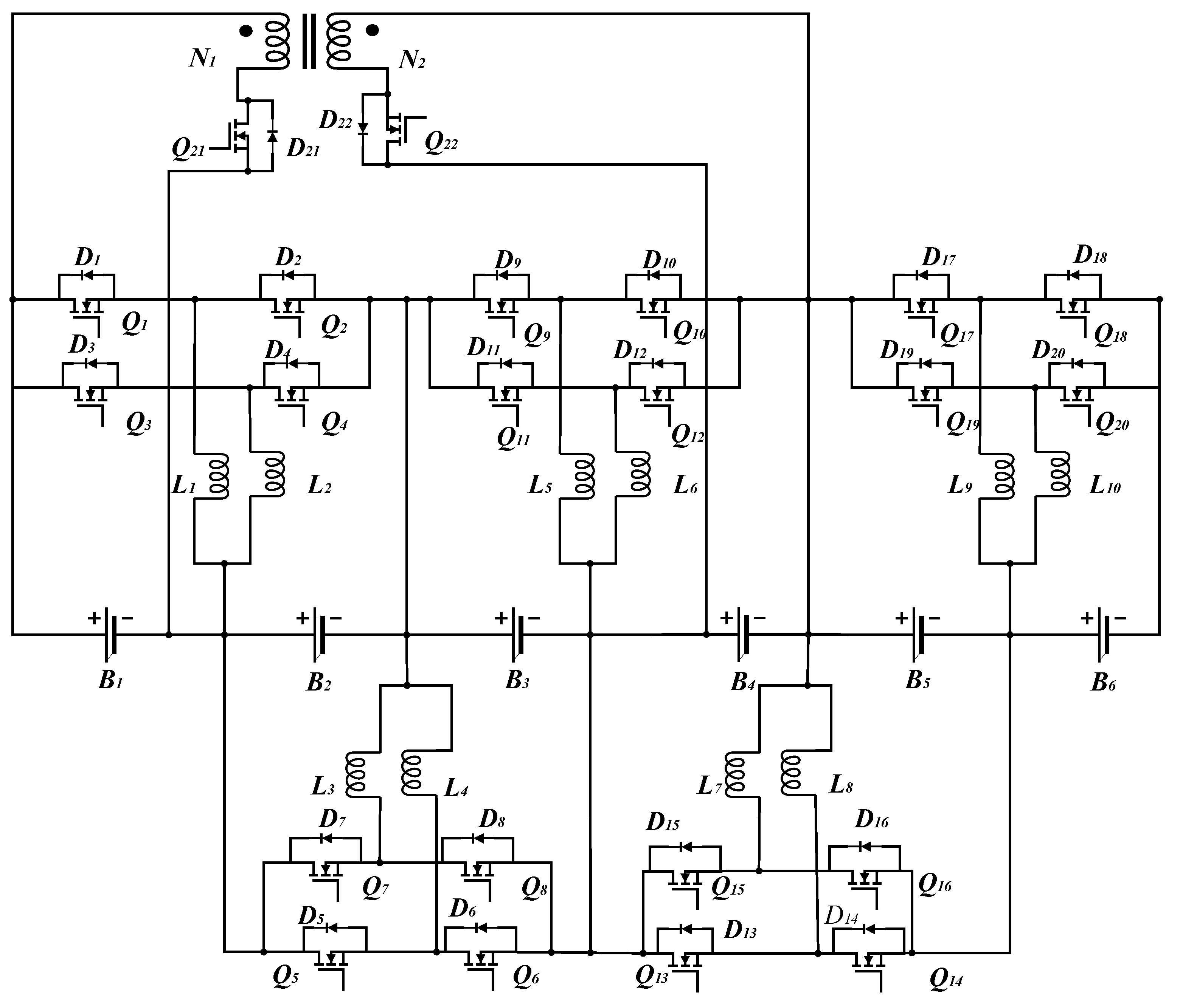
The hybrid balancing topology consists of 2 unique layers:
The inner-layer multi-inductor Buck-Boost module located internally to perform high-speed simultaneous adjacent-cell balancing between adjacent cells. The outer-layer balancing circuit module comprises two MOSFET switches and a set of transformers, enabling energy balancing between a single battery cell and other remaining cells within the battery pack.
The cross-cell energy transfer between non-adjacent cells is possible due to the outer-layer bidirectional flyback converter to eliminate the losses occurring in multi-step transfers.
The multi-inductor was developed to be used in two alternative operating configurations; that is, parallel, and interleaved, to enable the comparison. In parallel, charging and discharging of two inductors are done concurrently to supply more effective balancing current without escalation of peak inductor current. The inductor in the interleaved arrangement is driven (conduction is doubled) with a 180° phase difference, therefore always making continuous current flow without magnetic saturation.
The coupled inductor was used to construct the bidirectional flyback converter that gives the energy storage and galvanic isolation features. Turns ratio of the transformer was chosen to be 1:1 in case the design would be easy and current flow reverse between primary and secondary windings will be better symmetrical. An outer-layer converter was connected between a head cell, wherein a specific cell was identified, and a cell in the mid-pack to apply the dichotomy-based balancing strategy in which the fewest number of transfers was possible to achieve full pack equalization.
3.4. Control Strategy Implementation
A state-of-charge (SOC)-based algorithm, with protection ensured through voltage thresholds, was applied for balance control. In the simulation environment, SOC estimation was directly derived from the modeled battery capacity and charge/discharge flow, thereby avoiding estimation error and allowing the focus to remain on control performance. Three programmed balancing strategies were designed for comparison:(a) SOC-only balancing and (b) voltage-only balancing;(c) segmented bi-variable balancing, in which SOC control was applied in the mid-SOC range (20–90%), while voltage control was applied at the high and low SOC boundaries.
In each strategy, there was a continuous control system that averagely monitored all cells to determine the cell with the most-SOC and the lowest-SOC as the energy donor and the energy recipient respectively. This was done in the inner-layer modules as adjacent transfer, whereas in the outer-layer flyback converter direct cross-cell transfer was performed when the imbalance has become above a configured threshold. MOSFET switching control was managed with PWM commands that were programmed with duty cycles based upon equations derived on the principle of operation at the Buck-Boost and flyback converter based on Discontinuous Conduction Ordinary (DCM).
3.5. Simulation Environment and Parameterization
MATLAB /simulink simulation was set up using a continuous-time solver in order to represent switching consequences and transient actions with precision. In the power electronics models, non-ideal switch parameters of finite on-resistance and diode forward voltage drop were represented, but parasitic inductances and leakage capacitances were not. Inductance values of the Buck Boost modules were chosen so that the peak currents do not exceed 6 A (single inductor) with satisfactorily close proportional values in the multi-inductor ones. To operate the bidirectional flyback stage in DCM operation, wherever the coupled inductance was determined so that each switching cycle demagnetized fully.
The MOSFET switch control signals of the circuits in the Buck Boost modules was at fixed duty cycle of 50 per cent and a fixed switching period based on peak current desired whereas in flyback converter the switching signals had the duty cycle adjusted in order to have a DCM at all no-loads. The duration of the simulation in each of the scenarios was determined to ensure that the full balancing process was observed till the SOC variation among all cells dropped to less than 1 percent (0.01).
3.6. Evaluation Scenarios
Performance of the circuit was assessed under three operational conditions:
- No external load (resting state), to determine pure balancing ability unimpeded by load current or charging currents.
- State of charging (1 A constant current), to test the capacity of balancing system regarding the simultaneous operation with the inflow of energy.
- State of Free discharge (1 A constant current load), to test balancing at simultaneous energy out.
The times in which to balance was measured, the peak current stresses, and the transferring of the energy were recorded in each condition. The comparison of the results of the proposed hybrid topology was done with that of the conventional single inductor balancing and multi-inductor-only based designs.
3.7. Performance Metrics
The most important performance indicators were:
Time balancing: that is, the total time it takes to get ΔSOC less than 1%.
Presentation stability: Current rating: to make sure that inductors and switches used safe current values.
Energy transfer efficiency: this was calculated as the ratio of the energy which has been gained by the low-SOC cells and the amount of energy that was extracted by the simulator by the high-SOC cells, taking into consideration the resistive and switching losses in the simulation.
Thermal proxy estimation: although the direct implementation of thermal modeling was not performed, observation of RMS current values was used to deduce relative heating ability.
The relative study was done to measure the percentage saves on balancing time and trade-off between complexity and performance improvement.
4. Simulation Model and Results
4.1. Simulation Model Setup
To verify the feasibility of the aforementioned balancing circuit and its strategy, simulation experiments will be conducted in MATLAB/Simulink, with the battery's nominal capacity set to 6 Ah.
During the simulation:
The allowable State of Charge (SOC) range for the batteries is set to [0–100%]. Balancing is considered complete when the SOC difference between adjacent batteries in the pack is less than 0.01 (1%). The balancing time is defined as the duration from the start to the end of the balancing process. The initial SOC values of the batteries within the pack are randomly selected, as illustrated in Figure 2.
4.2. Simulation Analysis and Results of the Traditional Single-Inductor Circuit
Based on the theoretical analysis of the Buck-Boost circuit operating principle from prior work, a balancing circuit simulation model was constructed in Matlab/Simulink, as shown in Figure 3 below. This simulation model comprises of three main functional modules. The battery pack module within the blue box consists of six 3.2V lithium-ion single cells connected in series; the traditional single-inductor balancing units are within the yellow box, totaling five units; and the current source module is in the red box, primarily used for charge and discharge simulation.
To investigate the balancing performance of the circuit, the lithium battery voltage was set to the conventional 3.2V, rated capacity to 6Ah, inductor L to 1H, MOSFET conduction resistance to 100mΩ, wiring resistance assumed ideal, and the duty cycle of the control signal set to 50% with an amplitude of 1. The period of the MOSFET is calculated to be approximately T on =1.9 s, the peak current of the inductance is 6 A, and the design control signal parameter values are verified for rationality through the simulation model. In the Powergui simulation module, the system was configured for continuous-time operation, with the pulse control signal set to a 50% duty cycle, an amplitude of 1, and a period of 3.8 s (determined through calculation). Figure 4 shows the variation curve of the control signal over time in the balancing unit. Figure 5 presents the current variation curve through the inductor in the balancing unit.
From the above current variation curve, it can be concluded that the peak balancing current of the inductance is 6 A, the current varies between 0 and 6 A, meeting the initial design requirements. Due to the relatively long control signal period, the current variation in the inductance exhibits linear characteristics. In practical applications, the peak balancing current can be appropriately increased based on the selected battery and hardware circuit structure, to reduce the system response time.
After completing the general configuration, the initial SOC values of the six individual battery cells were set to 0.88, 0.85, 0.82, 0.80, 0.77, and 0.75 respectively (Figure 2), with a 900-second simulation conducted on the lithium-ion battery pack's single-layer balancing topology circuit under three operational states - standby, charging, and discharging - with the corresponding simulation results shown in Figure 6.
Figure 6.
Simulation results of traditional single-layer single inductance balancing.
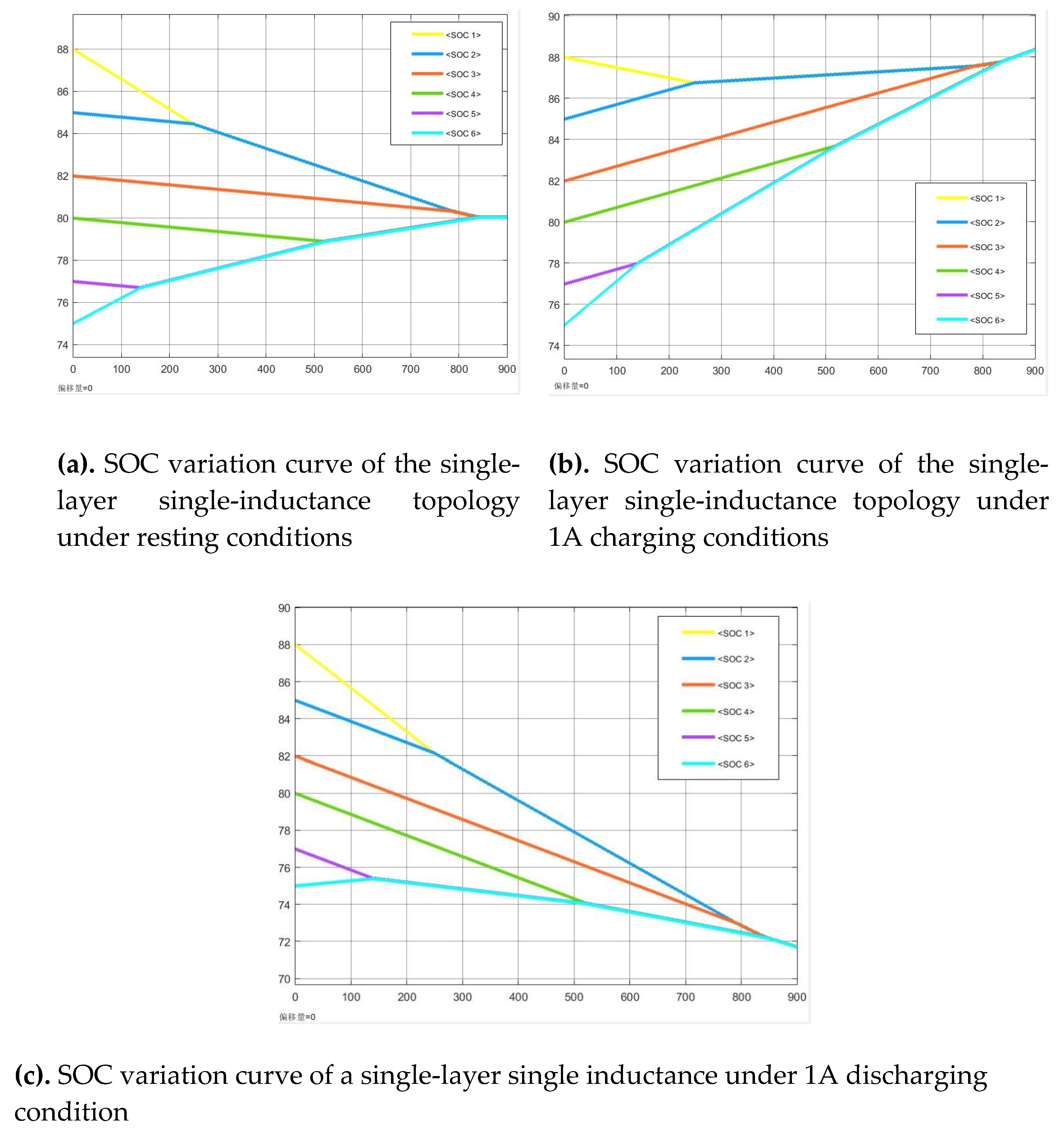
The simulation results of the conventional single-layer balancing model indicate that the time required to reach equilibrium state under standby, charging and discharging conditions are 845s, 837s and 850s respectively. The relatively long balancing time is attributed to the significant SOC variations (ranging from 0.75 to 0.88) among battery cells B1-B6, as the balancing process solely relies on adjacent-cell equalization modules which have limited power transfer capability between non-adjacent cells. In practical applications, energy storage battery packs and electric vehicle battery packs typically contain a large number of single cells. If the aforementioned balancing topology is employed, the balancing speed will substantially decrease. To address this issue, this paper optimizes and improves the traditional single-layer balancing topology structure by proposing a multiple inductor balancing circuit topology structure.
4.3. Simulation Analysis and Results of Single-Layer Multiple Inductor Balancing
This section analyzes the balancing performance of the single-layer multi-inductor balancing circuit topology and constructs a balancing circuit simulation model in Matlab/Simulink, as shown in Figure 7. The balancing sub-circuit module within the yellow box is replaced by a multi-inductor balancing unit.
As analyzed previously, the multi-inductor balancing unit employs a dual-inductor multi-path architecture with two distinct operating modes to enhance balancing efficiency across battery cells. Figure 8 demonstrates the total current through both inductors in Mode 1 (parallel inductor configuration), while maintaining the same control signal parameters (50% duty cycle, 3.8s period) as specified in Figure 8 below.
The current flowing between the two inductors, as shown in the above figure, remains within 0 to 6A. According to the current variation curve in the figure, the peak balancing current flowing through the loop is approximately 12A, with a current range of 0 to 12A. This operating mode doubles the balancing efficiency by increasing the balancing current between the batteries without increasing the inductance peak current, thereby enhancing the balancing speed.
Under operating Mode 2 (interleaved dual-inductor configuration), the current characteristics of the balancing sub-circuit are presented as follows: Figure 9(a and b) shows the current waveform through inductor 1, Figure 10(a and b) displays inductor 2's current profile, and Figure 11 illustrates the combined current through both inductors.
As evidenced in Figure 9 and Figure 10, both inductor 1 and inductor 2 exhibit identical peak currents of 6A with an operational range of 0-6A, while inductor 2 demonstrates a half-cycle (1.9s) phase delay. Figure 11 reveals that the combined inductor current remains stable within 5.4-6A. Simulation results confirm that this improved topology achieves three key advancements through time-interleaved current regulation: (1) maintaining the original 6A peak current while doubling effective conduction time via optimized MOSFET switching sequences; (2) preventing magnetic saturation through current phase-shifting; and (3) doubling balancing efficiency without increasing peak current requirements, thereby accelerating equalization speed.
Building upon these two optimization strategies, the enhanced simulation model was systematically evaluated under three operational conditions (standby, charging, and discharging), with detailed results presented in Figure 12 (a, b and c). The data demonstrates significant improvements in both balancing duration and energy transfer efficiency across all test scenarios.
From analyzing Figure 12, It can be concluded that the single-layer multiple-inductor balancing parallel topology reaches the balancing state under three conditions at resting 434 s, charging 431 s, and discharging 435 s, respectively. Compared with traditional single-inductor balancing, the efficiency of adjacent cell balancing is improved; however, node currents ranging from 0 to 12 A may impose significant stress on the circuit.
From Figure 13 above, it can be observed that the balancing times for the single-layer multi-inductor interleaving balancing structure under the three states are 424 s for resting, 421 s for charging, and 426 s for discharging, respectively. For the multiple inductor parallel balancing circuit, while ensuring circuit stability, the efficiency of adjacent cell balancing is also enhanced, with a stable node current of 5.4–6 A, providing strong stability for the designed circuit and a slight advantage of approximately ten seconds in balancing time. However, the multi-inductor balancing circuit still requires a relatively long balancing time for cross-cell balancing.
4.4. Dichotomy-Based Hybrid Balancing Simulation Analysis and Results
Firstly, the coupled inductance in the circuit is calculated to determine the inductance value. The relevant parameters of each single cell and MOSFET are set, and the final established model is as follows as shown in Figure 14. A bidirectional flyback balancing module is primarily added between Battery 1 and Battery 4 to implement the 'dichotomy-based' balancing approach between batteries.
Since the number of single cells on both sides of the coupled inductor is equal, the original turns ratio of the secondary winding is set as N1:N2 = 1:1. To ensure the coupled inductor operates in Discontinuous Conduction Mode for effective magnetic flux reset, the duty cycle of the MOSFET switch control signal is set to 0. 5. According to equation (1), the peak current can be calculated as:
The primary side voltage V1 is 3.2 V, Ton = 1.9 s, Imax = 6 A, thus the primary coupled inductance is 1.013 H. For computational convenience, the primary inductance was set to approximately 1 H. Figure 15 shows the corresponding primary current waveform.
In accordance with the principles of controlled experimental design, this study adopts simulation parameter configurations identical to those of the previously described balancing circuit to ensure the validity of experimental comparisons. The initial SOC values of each single cell are 88, 85, 82, 80, 77, and 75, respectively. After the balancing process, the maximum deviation of the state of charge (SOC) between adjacent single cells is controlled within an absolute value of 0.01. Systematic analyses are conducted under resting, charging, and discharging operating conditions. Relevant simulation results are detailed in Figure 16 as shown:
From Figure 16, it can be observed that the time to reach the balanced state for the Buck-Boost multi-inductor and bidirectional flyback hybrid balancing circuit structure under three conditions is 306 s at resting, 303 s during charging, and 308 s during discharging. Compared with the multiple inductor parallel balancing circuit, the hybrid balancing circuit shortens the energy transfer distance between cells while ensuring circuit stability. Compared to the traditional single-inductor scheme, the balancing time is reduced by 63.2%–64.8%, demonstrating the feasibility of this hybrid topology.
As shown in Table 1, the simulation balancing results of various balancing topologies under three operating states: resting, charging, and discharging (with the same initial SOC) are presented as follows:
Analysis of the simulation results for each balancing topology under resting, charging, and discharging states reveals that the multiple inductor design, employing parallel or interleaved layouts, reduces balancing time to approximately 50% of that of the traditional structure. Furthermore, the dichotomous hybrid topology further compresses the balancing time to 36% of the traditional scheme, demonstrating superior balancing efficiency and enhanced performance.
4.5. Research on Multi-Variable Cooperative Balancing Strategy for Lithium-Ion Battery Packs
To enhance the balancing performance of the battery management system, this part of the paper systematically investigates multivariate collaborative balancing strategies based on voltage, state of charge (SOC), and the combination of voltage and state of charge (SOC). Through comparative analysis of the characteristics of each variable, a segmented bivariate balancing scheme is proposed, and a simulation evaluation model is developed to validate its effectiveness.
4.5.1. Variable Characteristics
- (1)
- Voltage Variable: Using Open-Circuit Voltage (OCV) as the balancing criterion offers advantages such as high sampling accuracy and fast response; however, voltage fluctuations are significant under dynamic conditions, which can lead to under- or over-balancing issues, thus requiring threshold optimization in conjunction with operating states.
- (2)
- SOC variable: accurately characterizes battery inconsistency but depends on high-precision estimation algorithms, resulting in limited real-time capability and high computational complexity.
Comparison of various balancing variables Table 2 as shown:
4.5.2. Balancing Strategy
Balancing Strategy 1: Using battery SOC as the sole balancing variable. Balancing within the battery pack is achieved by monitoring the SOC of each individual cell.
Balancing Strategy 2: Using the battery voltage as the balancing variable. Voltage is a critical indicator for assessing battery status; balancing within the battery pack is achieved by monitoring the voltage of each cell.
Balancing Strategy 3: Using voltage and SOC as segmented bivariate balancing variables. According to the battery OCV-SOC curve, voltage is employed as the balancing variable in the low/high SOC regions (0–20%, 90–100%), while the SOC variable is applied in the mid SOC region (20–90%).
4.5.3. Balancing Criteria
This paper selected voltage and SOC as balancing variables, using their standard deviation as the criterion for determining the completion of balancing, as shown in the following formula [2].
Where x represents voltage and SOC. The average value of represents the mean voltage or SOC. represents the number of cells. When SOC is used as the balancing variable, <0.01 is considered to satisfy the balancing condition. When voltage is the balancing variable, <10 mV is considered to satisfy the balancing condition; the segmented bivariate approach is the same.
4.5.4. Control Strategy Simulation Analysis
The previous section analyzed the simulation of three balancing topologies. Here, the three balancing strategies are simulated and analyzed using a bisection method-based hybrid balancing circuit. This paper configures a retired lithium battery pack consisting of 6 cells with 6AH capacity, conducting a systematic analysis of three operating states: resting, charging, and discharging. The initial SOC of the battery in these three states are shown in Table 3 below:
Balancing results under resting conditions are as follows:
Figure 17.
Balancing results under resting conditions.
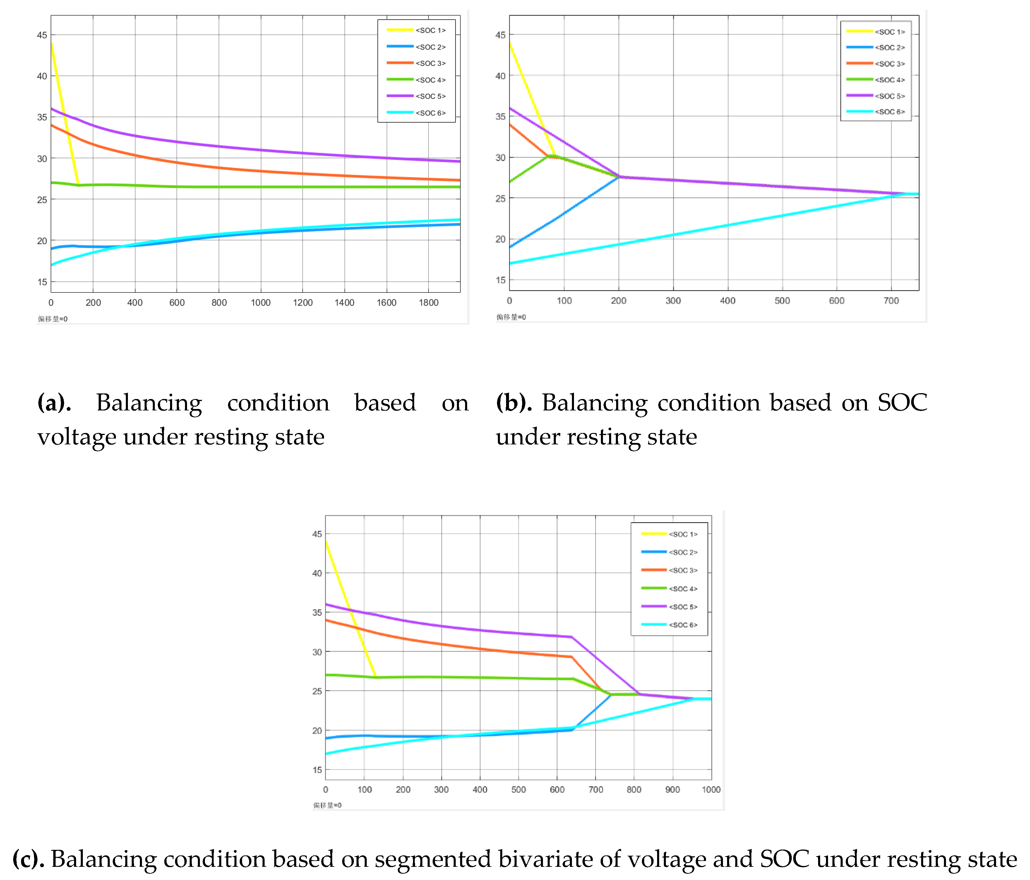
Under resting conditions, using voltage as the single-variable balancing condition, the balancing process has not completed at 1950s but is gradually approaching equilibrium. Using SOC as the single-variable balancing condition, the balancing completes at 727s, while using the segmented bivariate of voltage and SOC, the balancing completes at 956s. Strategy 1 exhibits the fastest balancing speed.
Balancing results under 1A charging condition are shown in Figure 18 as follows:
Under 1A charging condition, using voltage as the single-variable balancing condition, balancing is not completed at 1950s; using SOC as the single-variable balancing condition, balancing is completed at 504s; using segmented bivariate voltage and SOC, balancing is completed at 1075 s. Strategy 2 demonstrates the fastest balancing speed.
Balancing results under 1A discharging condition are as shown in Figure 19 as follows:
Under 1A discharging condition, using voltage as the single-variable balancing condition, balancing is not completed at 1950 seconds; using SOC as the single-variable balancing condition, balancing completes at 322 seconds; using segmented bivariate of voltage and SOC, balancing completes at 730 seconds. Strategy 1 achieves the fastest balancing speed.
As shown in Table 4, the figure illustrates the simulation-based balancing results of the various strategies under three operating states: resting, charging, and discharging (each with three different initial SOCs). The simulation results of the “dichotomous” hybrid model were analyzed under these three strategies across the operating states.
From the above table, it is evident that under the three operating states, using voltage as the balancing criterion cannot achieve precise balancing within a short time. In contrast, the SOC single-variable balancing strategy demonstrates superior balancing efficiency compared to the voltage and SOC segmented bivariate balancing strategy, particularly during charging and discharging, where the balancing efficiency improves by 52.1%-55.9% relative to the segmented bivariate strategy.
5. Discussion
The simulation results achieved in this paper have shown that the proposed solution of a Buck-Boost multi-inductor and bidirectional flyback hybrid balancing topology result in significant improvements in the balancing speed and efficiency against standard single-inductor solution and the standard multi-inductor only. The empirically determined 63.2% 64.8% decrease in the balancing time in comparison to the single inductor topology proves the hypothesis that with the use of the cross-cell transfer mechanism alongside the topology of adjacent-cell balancing, paths of energy redistribution become much shorter. This observation agrees with the result by Wei et al., [65], which stated that multi-path balancing systems are more efficient in large series-connected packs by design since the cumulative conversion losses are lower.
The inner-layer multi-inductor structure is critical to the acceleration of adjacent-cell equalization. At parallel mode, the effective doubling of current flow achieved a balancing approximation that was approximately 49 percent faster than was achieved in the baseline, using one inductor. Whereas this optimization resembles the observations on improving the work of Sun et al. [66], in which greater balancing current directly translated to more rapid equalization, we also found that a rise in peak current may present possible issues, as seen in the thermal stress cautioning possessed by Park et al. [67]. These peak stresses were mitigated using an interleaved configuration, which preserved the virtually identical balancing times, a performance trade-off that has been emphasized with unified or multi-phase converter designs by Huang et al. [68], who observed that interleaving could reduce the effects of thermal distributions and increase component life without any limitation in throughput.
The bidirectional flyback converter operating at the outer layer successfully filled large SOC gaps between non-adjacent cells because of its capacity to deliver power in both directions in contrast to unidirectional converters. In opposition to the cascaded adjacent transfers, which inevitably present conversion inefficiency build up, the flyback stage allows direct energy repositioning, as a result of which the speed and energy usage are enhanced. Cross-cell transfers with similar advantages have also been derived by Kumar et al., [69] in the balancing using multi-winding transformers, but it was at a cost of efficiency since their method was subject to the core losses, and in our design such an issue was overcome by operating in discontinuous conduction mode (DCM). DCM operation guarantees complete demagnetization on every cycle causing a reduction in core heating, which is also suggested in isolation transformer design investigations by Chen et al. [70].
Comparison of control strategies revealed that the SOC-only strategy returned the shortest balancing times when compared to the voltage-only and the segmented bi-variable strategies, in all operating states. This agrees with the findings of Abbas et al. [71] who discovered that SOC-based algorithms are more consistent in dynamic load circumstances as they are immune to transient induced voltage changes. Nevertheless, the point that SOC-only control is the superior one in simulation is premised on perfect accuracy of SOC estimation, which is difficult to obtain in the reality. In practical systems, any error in estimating the SOC caused by sensor naivete, model errors and temperature, can result in performance degradation, which is stressed by Pahlevaninezhad et al., [72]. This indicates that although SOC-only based control is the best solution in a synthetically-ideal test bed, other hybrid control techniques can be more robust on the physical level, in particular, more robust to noise in high-noise applications like bus-electric or maritime energy storage.
The inability of voltage-only control to attain balancing in the 1950-second simulation interval also confirms precedent findings by Koenig et al. [73] that voltage is not a good indicator resource that can provide accurate description of SOC of cells when they run under load condition, since voltage has hysteresis and non-linear OCV-SOC curves. This shows why in an advanced balancing algorithm used in high-performance applications, one should always include SOC or state estimation that is similar. The segmented bi-variable approach, although slower than the SOC-only, appeared to have potential within our results even though it does not require an accurate SOC estimation and has also been suggested by Lee et al. [74] to combine temperature and resistance variables and dynamically select among voltage and SOC requirements.
Practically, as an engineer, one can see even more benefits to the hybrid topology than simply evening out on speed. Using parallel and non-parallel mechanisms of transferring energy, the architecture automatically extends better to large packs. The same scalability has appeared in modular balance designs, including those by Murshid et al. [75] where multiple-levels of hierarchical balancing layers provided an order of magnitude scaling of equalization time per unit cell in 96-cell EV packs. This method has a similar ability to scale with less risk of complexity with regards to transformer windings, which is a disadvantage of fully transformer-based designs.
However, a number of limitations have to be considered. First, such simulations ignored the thermal effects, which could have a big impact on both the balancing efficiency and the reliability of the components in practice. Peak current stress can lead to local heating of the circuit which has the potential to modify the values of inductor resistance and MOSFET conduction losses, as reported by Dalala et al. [76]. Future work should incorporate electro-thermal co-simulation models to improve the accuracy of performance prediction. Moreover, the test case was limited to a six-cell design; while the design principles are extendable to larger battery packs, the influence of interconnection parasitics and the increasing complexity of control coordination must be carefully considered, as discussed by Wu et al. [77].
The other factor is efficiency trade-off between quickness and use of components. Increasing balancing currents decreases balancing time, but also conduction and switching losses, which may lead to an overall decrease in net energy efficiency, an aspect that has been amply discussed in converter optimization in the literature by Rahman et al. [78]. Our hybrid topology hopes to deal with this by limiting high-current working process to the inner-layer with moderate current flow at the flyback stage. The decision leads to a trade-off between speed and energy conservation, which agrees with the philosophy of designing mentioned by Mohamed et al. in their multi-stage active balancing study.
Lastly, the overall research has important implications on the target areas of its application, including EVs, stationary grid storage, and aerospace systems. Faster balancing may be of direct benefit to extended driving range and down time in EVs as demonstrated through life-cycle modeling research by Park et al. [80]. In grid storage applications, high-efficiency balancing increases capacity retention during partial cycling, increasing system return on investment optimizations as observed during the study by Zhang et al. [81]. The use of fewer energy transfer steps in our hybrid topology had the potential to enhance fault tolerance and performance of aerospace systems, where both factors are critically important (weight and reliability).
Overall, the discussion reiterates the fact that the major novelty of the work is the context of dual-layer balancing, which is concomitant to maximum adjacent and cross-cell imbalances, as run in an SOC-based control system. Although there are still limitations about scaling, thermal validation, and control adaptation to imperfect SOC estimation, the given findings resonate well with the rest of the literature repeating the idea that hybrid, multi-path balancing should be the next step towards the further development of such components of battery management system as high-performance battery modules.
Author Contributions
Conceptualization, Moses Arthur Baidoo and Zhicheng Wang; methodology, Moses Arthur Baidoo; software, Jie Cao and Moses Arthur Baidoo; validation, Bin Zhang, Jie Zhao and Wenjun Deng; formal analysis, Silong Quan; investigation, Moses Arthur Baidoo and Shenghang Yi; resources, Yuke Wu; data curation, Zhicheng Wang; writing—original draft preparation, Moses Arthur Baidoo; writing—review and editing, Zhicheng Wang; visualization, Jie Cao; supervision, Zhicheng Wang; project administration, Zhicheng Wang; funding acquisition, Zhicheng Wang. All authors have read and agreed to the published version of the manuscript.
Funding
This research was supported by the Major Science and Technology R&D Project of Jiangxi Province under Grant 20233AAE02008, titled “Research on Key Technologies and Equipment Development for Cascade Battery Energy Storage.”
Data Availability Statement
The data that support the findings of this study are available from the corresponding authors, upon request.
Conflicts of Interest
The authors declare no conflicts of interest.
Abbreviations
The following abbreviations are used in this manuscript:
| LIBs | Lithium-Ion Batteries |
| DCM | Discontinuous Conduction Mode |
| MATLAB | Matrix Laboratory |
| SOC | State-of-Charge |
| EVs | Electric Vehicles |
| BMS | Battery Management Systems |
| OCV | Open-Circuit Voltage |
| AEKF | Adaptive Extended Kalman Filter |
| PWM | Pulse Width Modulation |
| RMS | Root Mean Square |
References
- Nitta, N., Wu, F., Lee, J.T., & Yushin, G. (2015). Li-ion battery materials: Present and future. Materials Today, 18(5), 252–264.
- Armand, M., & Tarascon, J.M. (2008). Building better batteries. Nature, 451(7179), 652–657.
- Goodenough, J.B., & Park, K.S. (2013). The Li-ion rechargeable battery: A perspective. Journal of the American Chemical Society, 135(4), 1167–1176.
- Scrosati, B., & Garche, J. (2010). Lithium batteries: Status, prospects and future. Journal of Power Sources, 195(9), 2419–2430.
- IEA. (2023). Global EV Outlook 2023: Catching up with climate ambitions. International Energy Agency.
- BloombergNEF. (2023). Electric Vehicle Outlook 2023.
- BCC Research. (2024). Global Lithium-ion Battery Market: Powering the Future of Energy Storage.
- Zhang, S.S. (2006). The effect of the charging protocol on the cycle life of a Li-ion battery. Journal of Power Sources, 161(2), 1385–1391.
- Vetter, J., et al. (2005). Ageing mechanisms in lithium-ion batteries. Journal of Power Sources, 147(1–2), 269–281.
- Wang, Q., Ping, P., Zhao, X., Chu, G., Sun, J., & Chen, C. (2012). Thermal runaway caused fire and explosion of lithium-ion battery. Journal of Power Sources, 208, 210–224.
- Mahdy, O.A.A.M.L., et al. (2025). Quantitative evaluation of thermal runaway in lithium-ion batteries under critical heating conditions. Scientific Reports, 15, 24004.
- Feng, X. , et al. (2018). Thermal runaway mechanism of lithium ion battery for electric vehicles: A review. Energy Storage Materials, 10, 246–267.
- Piller, S. , Perrin, M., & Jossen, A. (2001). Methods for state-of-charge determination and their applications. Journal of Power Sources, 96(1), 113–120.
- Kim, M. , et al. (2014). Passive cell balancing for lithium-ion battery packs. IEEE Transactions on Industrial Electronics, 61(4), 2204–2213.
- Waag, W. , Käbitz, S., & Sauer, D.U. (2013). Adaptive on-line prediction of the available power capability of Li-ion batteries. Journal of Power Sources, 242, 698–714.
- Khaligh, A. , & Li, Z. (2010). Battery, ultracapacitor, fuel cell, and hybrid energy storage systems for electric, hybrid electric, fuel cell, and plug-in hybrid electric vehicles: State of the art. IEEE Transactions on Vehicular Technology, 59(6), 2806–2814.
- Yue, S. , et al. (2023). Temperature-considered active balancing strategy for lithium-ion battery packs with surrogate optimization. Applied Energy, 338, 120944.
- Lee, K.-M. , et al. (2015). Active cell balancing of Li-ion batteries using LC series resonant circuit. IEEE Transactions on Industrial Electronics, 62(9), 5491–5501.
- Tang, X. , et al. (2020). Run-to-run control for active balancing of lithium iron phosphate battery packs. IEEE Transactions on Power Electronics, 35(2), 1499–1512.
- Turksoy, A., et al. (2023). Optimal active battery balancing control for EV applications. Energy, 262(1), 125409.
- Sugumaran, G. , et al. (2024). Efficient buck-boost converter for fast active balancing of lithium-ion battery packs. Computers and Electrical Engineering, 118(B), 109429.
- Zhang, C. , et al. (2018). A review of supercapacitor modeling, estimation, and applications: A control/management perspective. Renewable and Sustainable Energy Reviews, 81, 1868–1878.
- Wang, S. , et al. (2022). SOC estimation for lithium-ion batteries: A review. Energies, 15(3), 1005.
- He, H. , et al. (2012). State-of-charge estimation of the lithium-ion battery using an adaptive extended Kalman filter based on an improved Thevenin model. IEEE Transactions on Vehicular Technology, 60(4), 1461–1469.
- Wang, H. , et al. (2017). A multi-mode active cell balancing strategy for lithium-ion battery packs. Journal of Power Sources, 348, 66–78.
- Zhang, H. , et al. (2019). Analysis of cell imbalance in lithium-ion battery packs. Journal of Energy Storage, 25, 100817.
- Jaguemont, J. , et al. (2016). Thermal management systems for EV batteries: A review. Applied Thermal Engineering, 96, 689–703.
- Berecibar, M. , et al. (2016). Critical review of state of health estimation methods of Li-ion batteries for real applications. Renewable and Sustainable Energy Reviews, 56, 572–587.
- Feng, X. , et al. (2019). Research on the mechanism and suppression of thermal runaway of lithium-ion batteries. eTransportation, 1, 100011.
- Lu, L. , et al. (2013). A review on the key issues for lithium-ion battery management in electric vehicles. Journal of Power Sources, 226, 272–288.
- Plett, G.L. (2015). Battery management systems, Volume II: Equivalent-circuit methods. Artech House.
- Lee, S. , et al. (2014). A new cell equalization method for large-scale Li-ion battery systems. IEEE Transactions on Vehicular Technology, 63(9), 4206–4215.
- Noh, M., et al. (2015). Analysis of energy efficiency in passive balancing circuits. Energy Conversion and Management, 96, 325–334. 96, 325–334.
- Shang, Y. , et al. (2018). Thermal behavior of passive balancing in large Li-ion battery packs. Applied Energy, 227, 865–875.
- Barreras, J.V. , et al. (2017). Active balancing systems for electric vehicles: A review. Energies, 10(9), 1290.
- Chen, Y., et al. (2019). Overview of battery cell balancing methods for EVs. IEEE Access, 7, 129335–129348.
- Kandasamy, K., et al. (2016). Analysis of switched capacitor battery balancing. Journal of Power Sources, 324, 50–60.
- Jiang, J., et al. (2015). Design and implementation of a bidirectional buck–boost balancing circuit. IEEE Transactions on Power Electronics, 30(12), 7159–7169.
- Kim, Y. , et al. (2017). Flyback converter-based balancing for high-voltage battery systems. IEEE Transactions on Industrial Electronics, 64(8), 6610–6619.
- Choi, J. , et al. (2016). Transformer design considerations for high-efficiency flyback converters. IEEE Transactions on Magnetics, 52(7), 1–4.
- Xu, B., et al. (2020). A hybrid switched capacitor and inductor balancing circuit for EV batteries. Energies, 13(10), 2518.
- Li, X. , et al. (2021). Multi-winding transformer-based active balancing for large-scale battery packs. IEEE Transactions on Power Electronics, 36(7), 7790–7801.
- Ouyang, Q., et al. (2018). Comparative study on hybrid battery balancing topologies. Journal of Energy Storage, 18, 509–518.
- He, H. , et al. (2021). Inter-module balancing system with dual-stage converter architecture. IEEE Transactions on Transportation Electrification, 7(3), 1332–1343.
- Zhao, X. , et al. (2020). Multi-port bidirectional flyback converter for battery balancing. IET Power Electronics, 13(9), 1662–1670.
- Martinez, C., et al. (2022). Control challenges in hybrid battery balancing systems. IEEE Transactions on Industrial Informatics, 18(9), 6162–6174.
- Hannan, M.A., et al. (2018). Review of control strategies for battery balancing. Renewable and Sustainable Energy Reviews, 75, 1363–1385.
- Zhang, W. , et al. (2016). Comparative study of SOC estimation methods for Li-ion batteries. Applied Energy, 183, 390–403.
- Guo, Y. , et al. (2019). OCV-based SOC estimation: Limitations and solutions. Journal of Power Sources, 444, 227320.
- Xiong, R. , et al. (2017). Advanced state estimation for lithium-ion batteries. Energies, 10(10), 1480.
- Zhou, Y., et al. (2020). Adaptive extended Kalman filter for SOC estimation in dynamic conditions. Energies, 13(2), 365.
- Liu, K. , et al. (2020). Machine learning-based SOC estimation for lithium-ion batteries. Journal of Energy Storage, 28, 101193.
- Park, S., et al. (2019). Deep learning approach to battery SOC estimation. IEEE Access, 7, 72069–72079.
- Wang, L. , et al. (2018). Multi-variable balancing control for EV battery packs. IEEE Transactions on Transportation Electrification, 4(2), 408–417.
- Yang, X. , et al. (2021). Cooperative voltage–SOC–temperature balancing for Li-ion batteries. Energies, 14(3), 755.
- Park, Y. , et al. (2020). Hierarchical balancing control in multi-mode battery systems. IEEE Transactions on Industrial Electronics, 67(12), 10578–10587.
- Ye, Y., et al. (2018). Modular battery management architectures. IEEE Transactions on Power Electronics, 33(5), 4394–4409.
- Zhou, D. , et al. (2020). Two-layer balancing strategies for modular EV battery packs. Energies, 13(17), 4569.
- Wang, X. , et al. (2019). Decentralized balancing control in large-format Li-ion battery systems. IEEE Transactions on Industrial Electronics, 66(3), 2221–2231.
- Cho, H., et al. (2017). Multiplexed balancing converter for EV battery systems. IEEE Transactions on Power Electronics, 32(6), 4676–4686.
- Li, W. , et al. (2021). Hardware validation of high-efficiency balancing circuits. IEEE Access, 9, 33522–33534.
- Sun, Z., et al. (2019). Scalability challenges in active balancing. Journal of Energy Storage, 24, 100748.
- Kang, L., et al. (2021). Reliability assessment of hybrid balancing systems. IEEE Transactions on Industrial Electronics, 68(12), 12341–12350.
- Shen, Y., et al. (2020). Benchmarking methods for active balancing performance. Energies, 13(15), 3920.
- Wei, Z., et al. (2021). Design considerations for multipath active balancing in EV battery systems. IEEE Transactions on Transportation Electrification, 7(4), 2781–2794.
- Sun, F. , et al. (2020). High-current active balancing for large-format lithium-ion batteries. Journal of Energy Storage, 30, 101486.
- Park, M. , et al. (2019). Thermal performance analysis of high-current battery balancing circuits. Applied Thermal Engineering, 154, 392–403.
- Huang, X., et al. (2017). Interleaved converter design for improved thermal distribution. IEEE Transactions on Power Electronics, 32(6), 4670–4683.
- Kumar, A. , et al. (2022). Multi-winding transformer-based balancing for modular battery packs. Energies, 15(12), 4335.
- Chen, L. , et al. (2016). Transformer design for high-efficiency isolated converters. IEEE Transactions on Industrial Electronics, 63(6), 3513–3524.
- Abbas, A. , et al. (2021). Comparative analysis of SOC-based and voltage-based balancing algorithms. Journal of Power Sources, 498, 229905.
- Pahlevaninezhad, M., et al. (2018). Impact of SOC estimation error on active balancing performance. IEEE Transactions on Energy Conversion, 33(4), 1943–1953.
- Koenig, S. , et al. (2017). Limitations of voltage-based balancing in dynamic load conditions. Energy Procedia, 138, 1003–1008.
- Lee, J. , et al. (2019). Hybrid voltage–SOC balancing for lithium-ion batteries. Energies, 12(7), 1298.
- Murshid, S., et al. (2021). Hierarchical modular balancing architecture for electric vehicles. IEEE Access, 9, 89157–89169.
- Dalala, Z.M. , et al. (2013). Electro-thermal modeling of power converters for battery management. IEEE Transactions on Power Electronics, 28(12), 5673–5686.
- Wu, J., et al. (2020). Scalability and communication challenges in large battery packs. IEEE Transactions on Smart Grid, 11(1), 497–507.
- Rahman, M.M., et al. (2019). Optimization of active balancing circuits for efficiency and speed. Journal of Power Sources, 412, 472–482.
- Mohamed, A. , et al. (2022). Multi-stage active balancing for high-voltage EV battery packs. IEEE Transactions on Industry Applications, 58(3), 3256–3267.
- Park, Y. , et al. (2021). Life-cycle benefits of fast active balancing in EV batteries. Energies, 14(14), 4196.
- Zhang, Y. , et al. (2018). Economic analysis of battery balancing in grid-connected storage systems. Energy, 153, 503–512.
- Luo, X. , et al. (2019). Fault-tolerant battery management for aerospace applications. IEEE Transactions on Aerospace and Electronic Systems, 55(5), 2396–2408.
Figure 2.
Initial SOC of the battery.
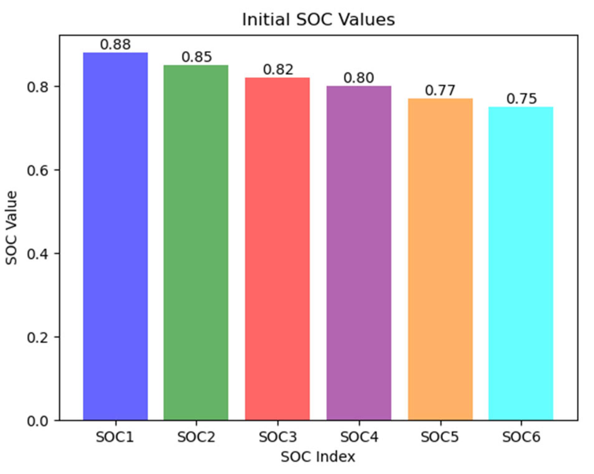
Figure 3.
Simulation Diagram of Single-Layer Balancing Circuit.
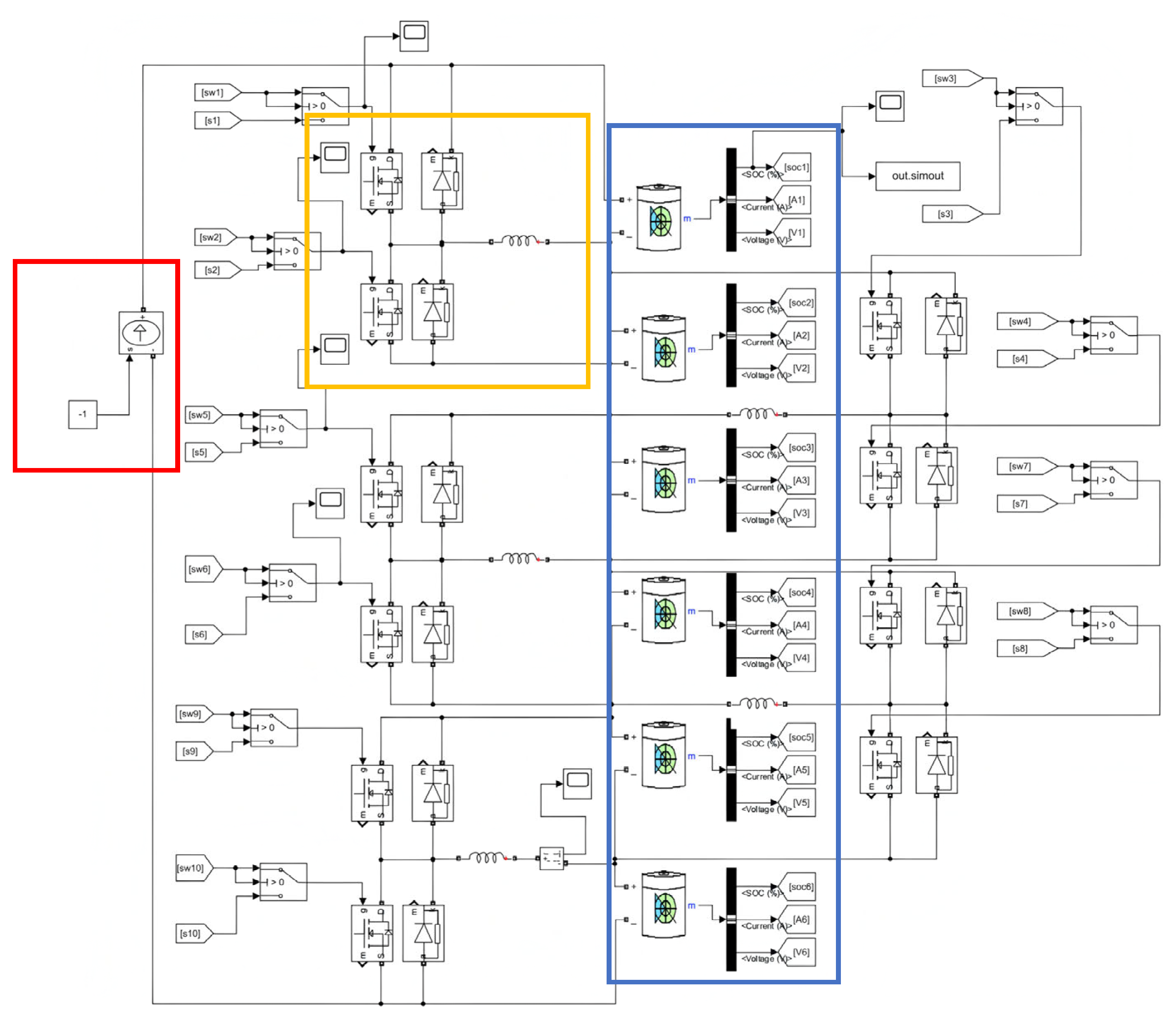
Figure 4.
Control signal variation curve.
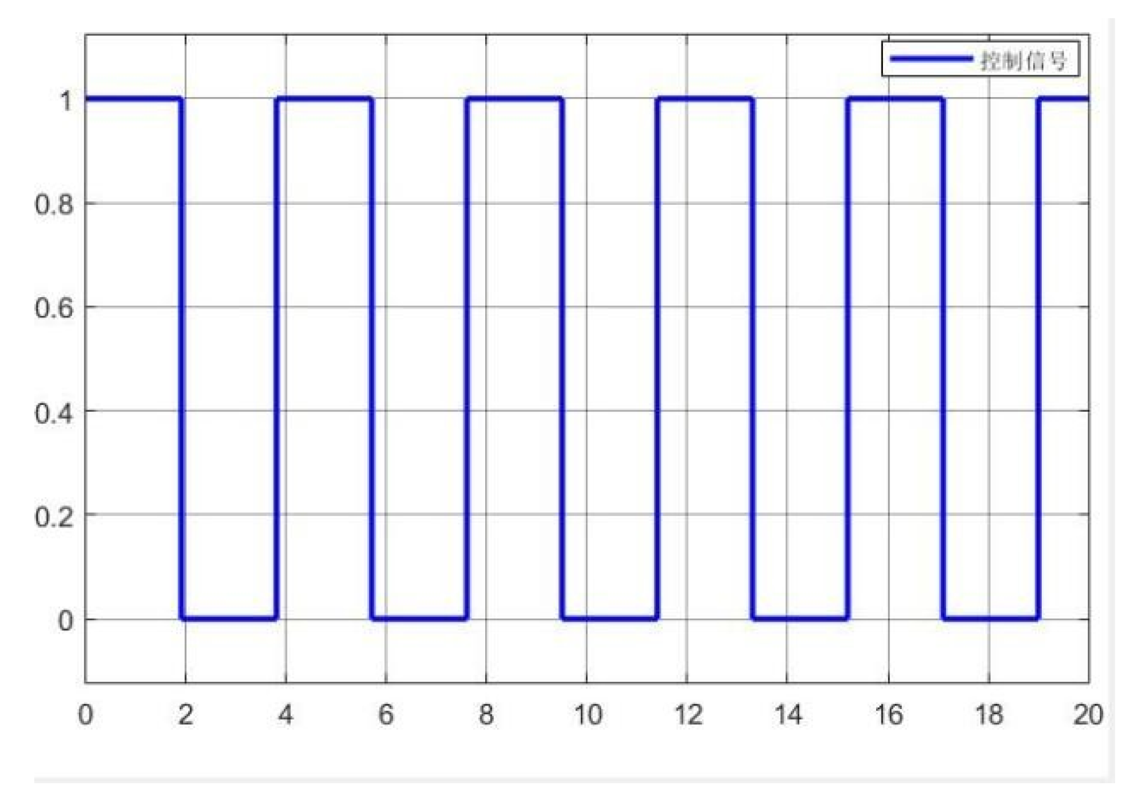
Figure 5.
Current variation curve flowing through the inductance.
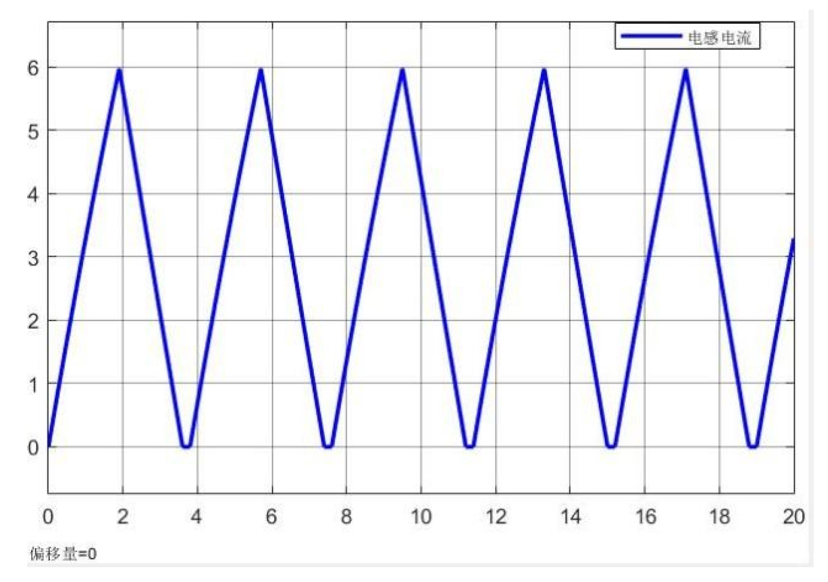
Figure 7.
Simulation diagram of single-layer multi-inductor balancing.
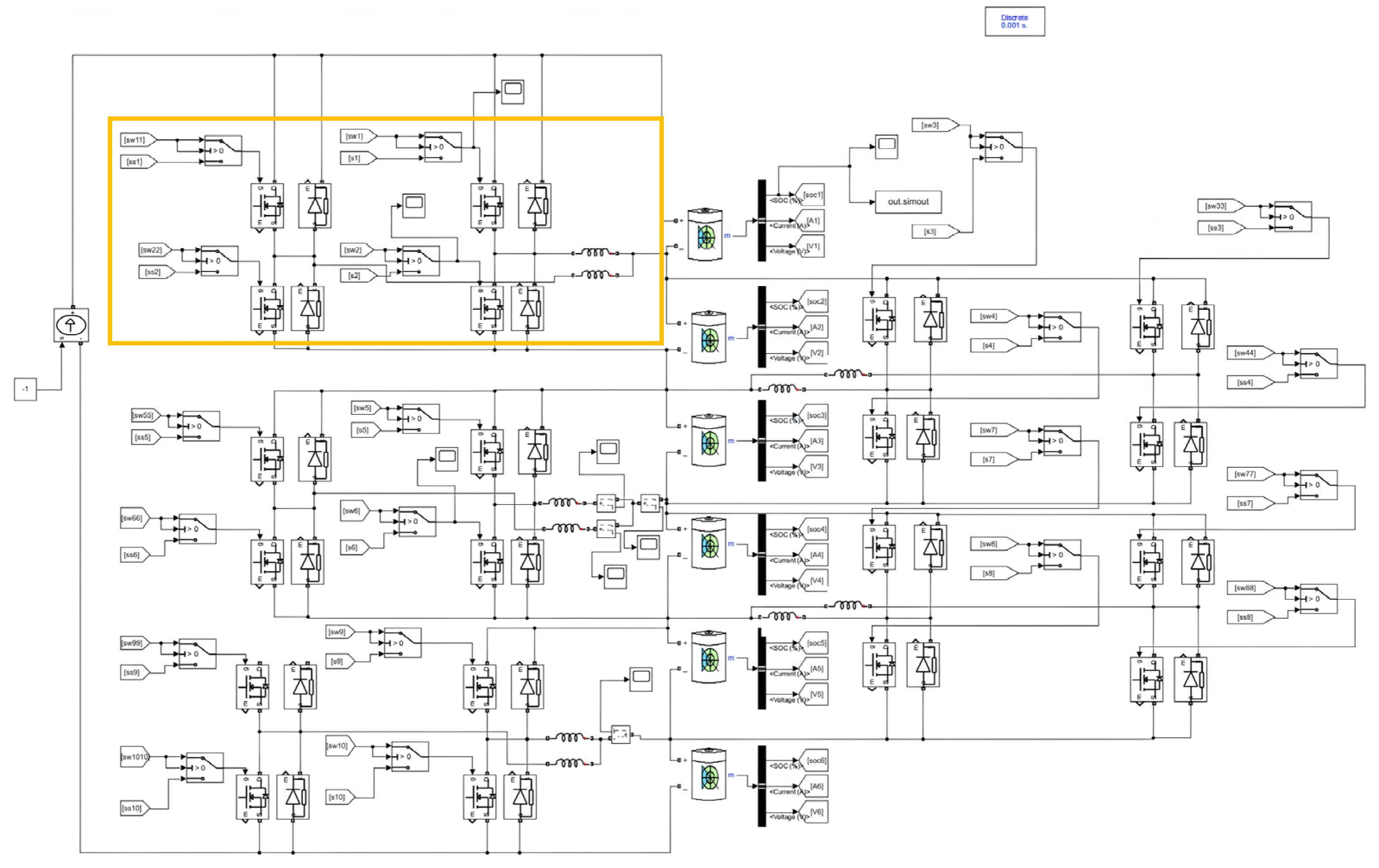
Figure 8.
The total current variation curve flowing through the dual inductors.
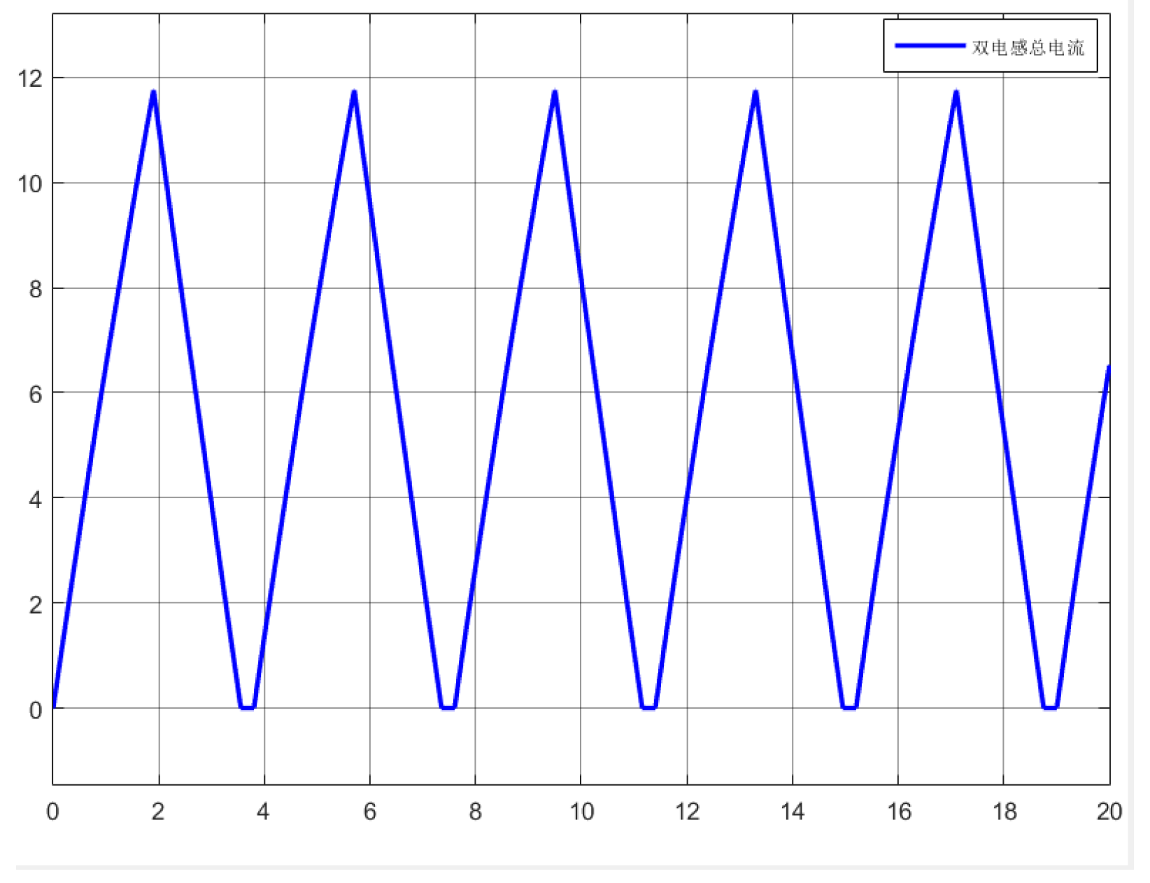
Figure 9.
Signal and current variations of Inductor 1 in the balancing sub-circuit.
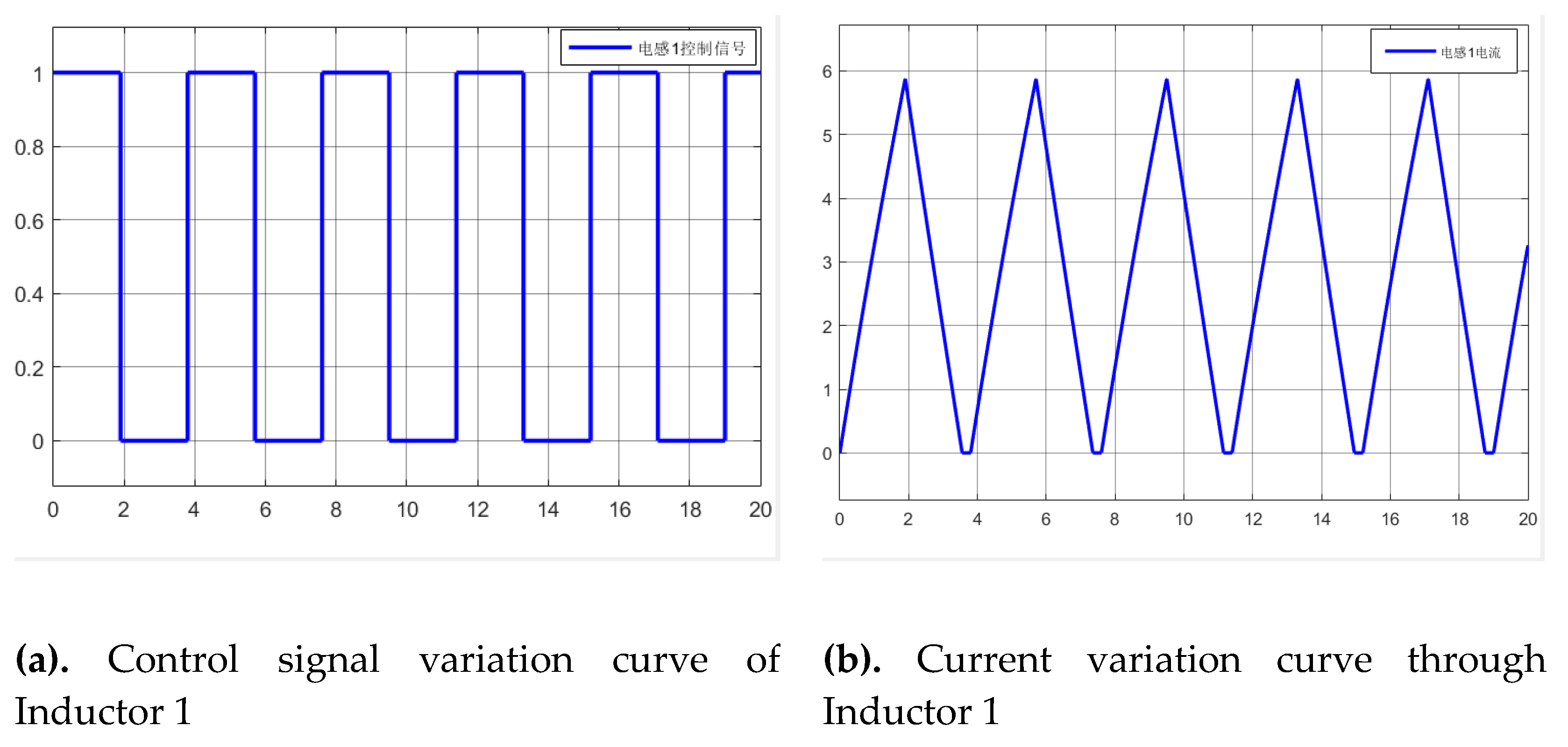
Figure 10.
Signal and current variations of Inductor 2 in the balancing sub-circuit.
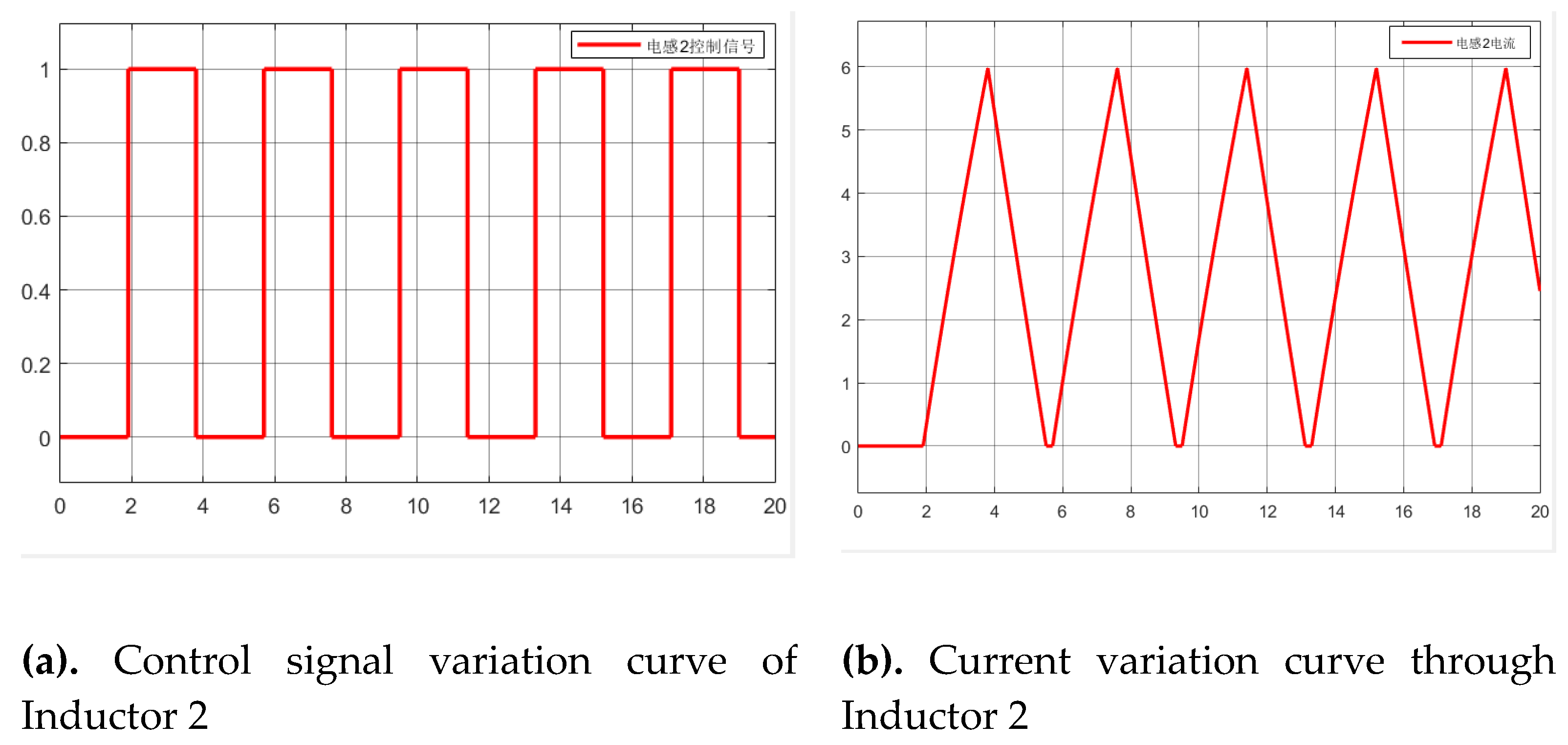
Figure 11.
The total current variation curve flowing through the dual inductors.
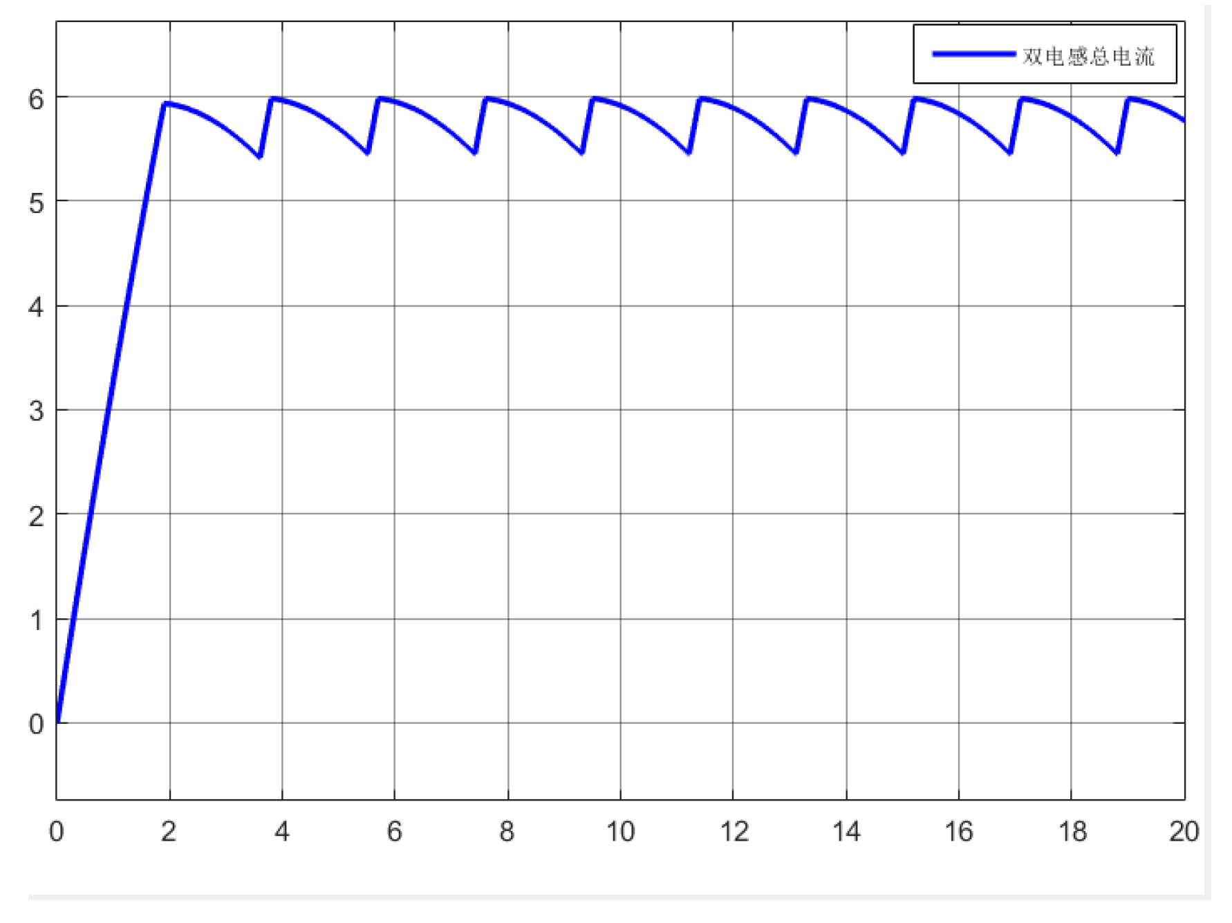
Figure 12.
Simulation results of single-layer multi-inductor parallel topology.
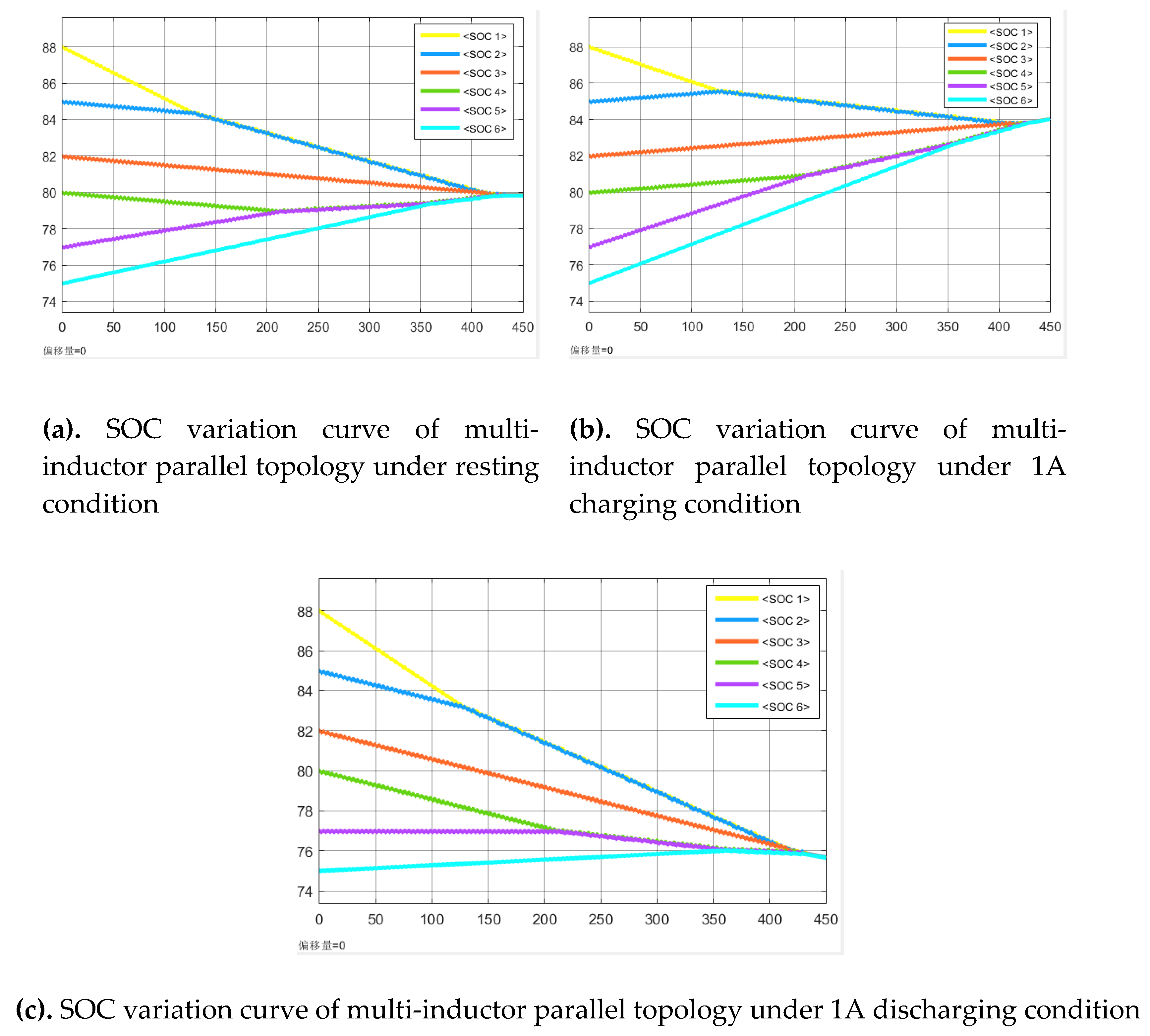
Figure 13.
Simulation results of single-layer multi-inductor interleaving.
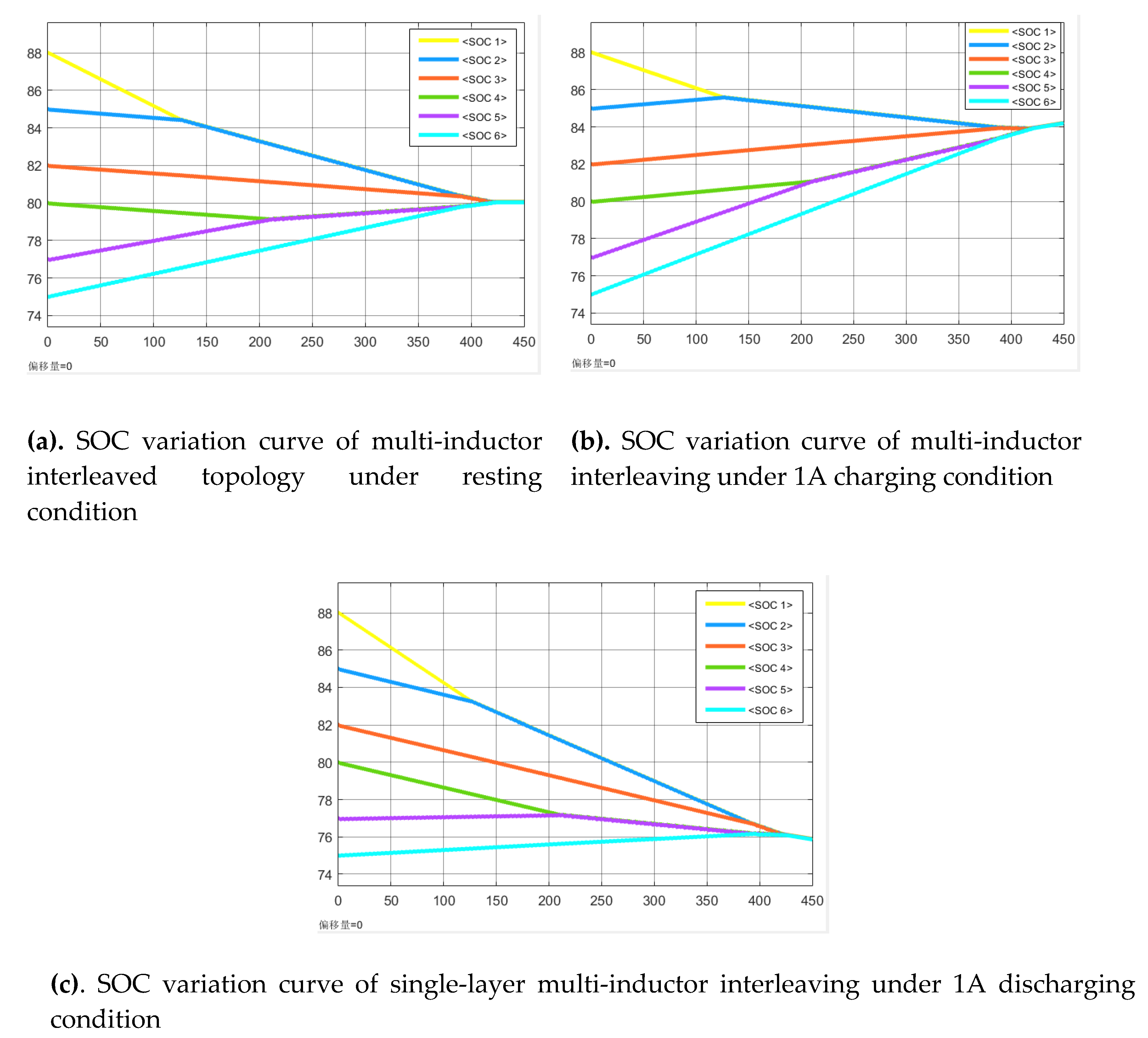
Figure 14.
Simulation diagram of "dichotomous" mixed balance.
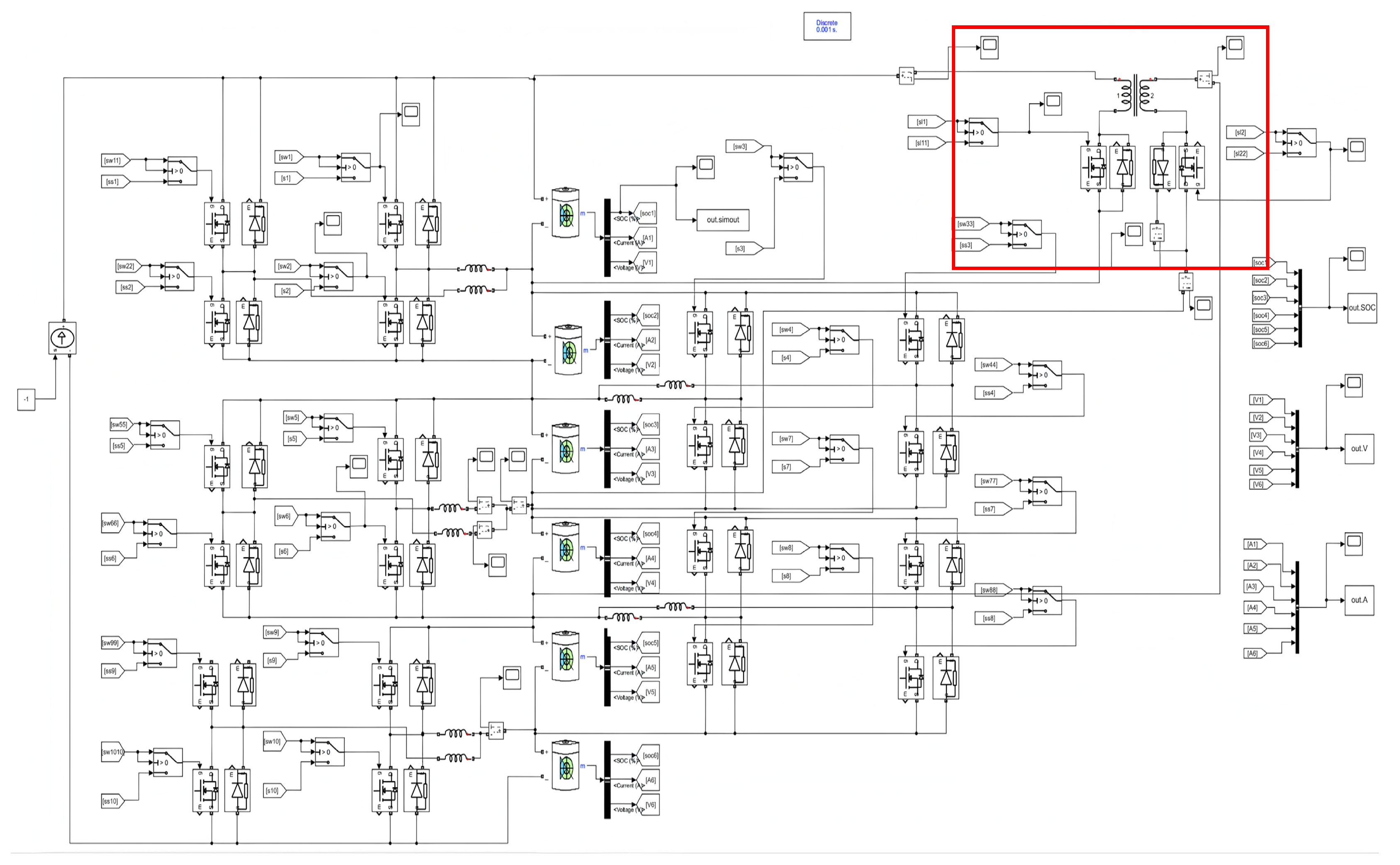
Figure 15.
Current variation waveform of the primary winding.
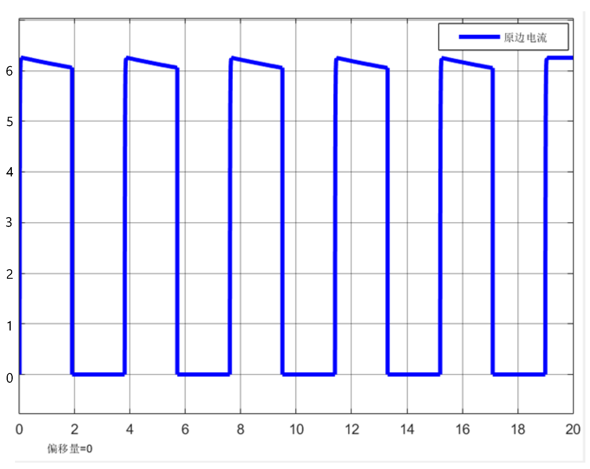
Figure 16.
Simulation result of "dichotomous" hybrid equalization circuit.
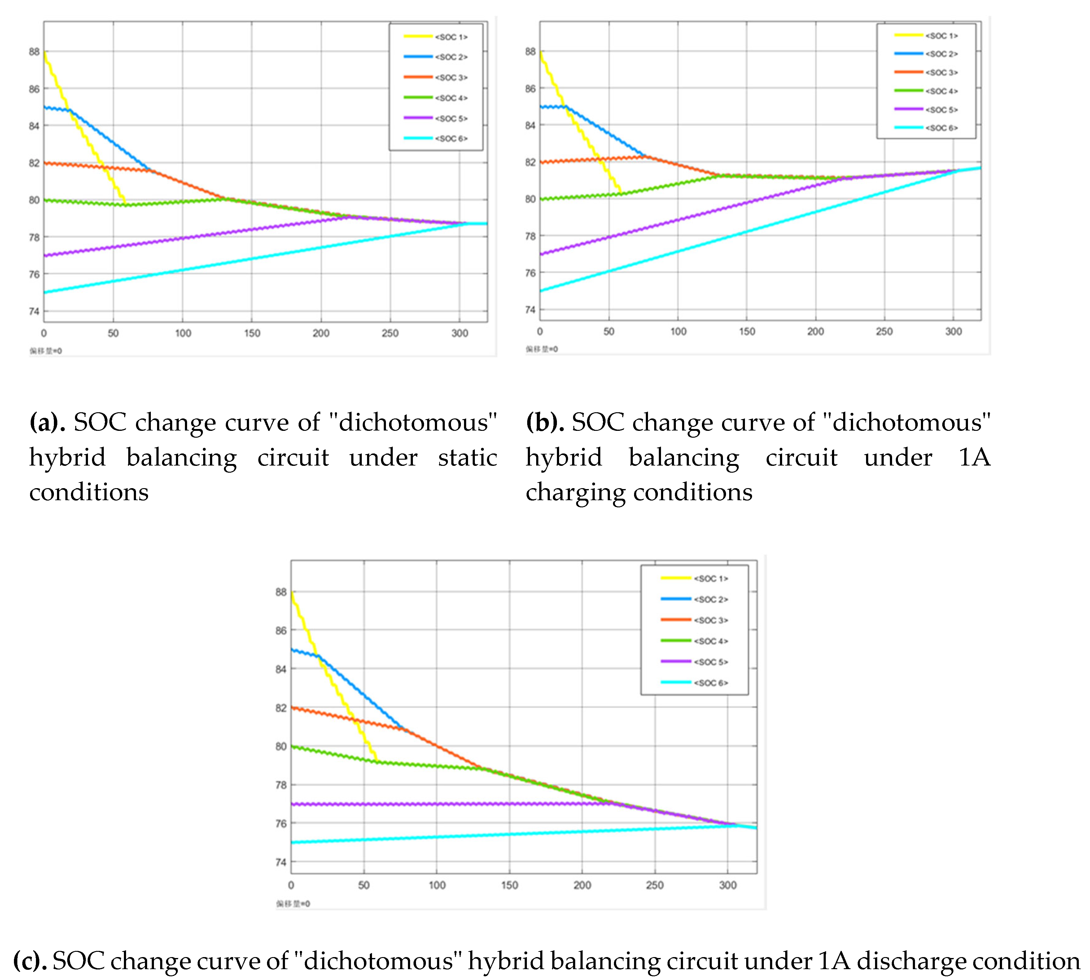
Figure 18.
Balancing results under 1A charging condition Figure.
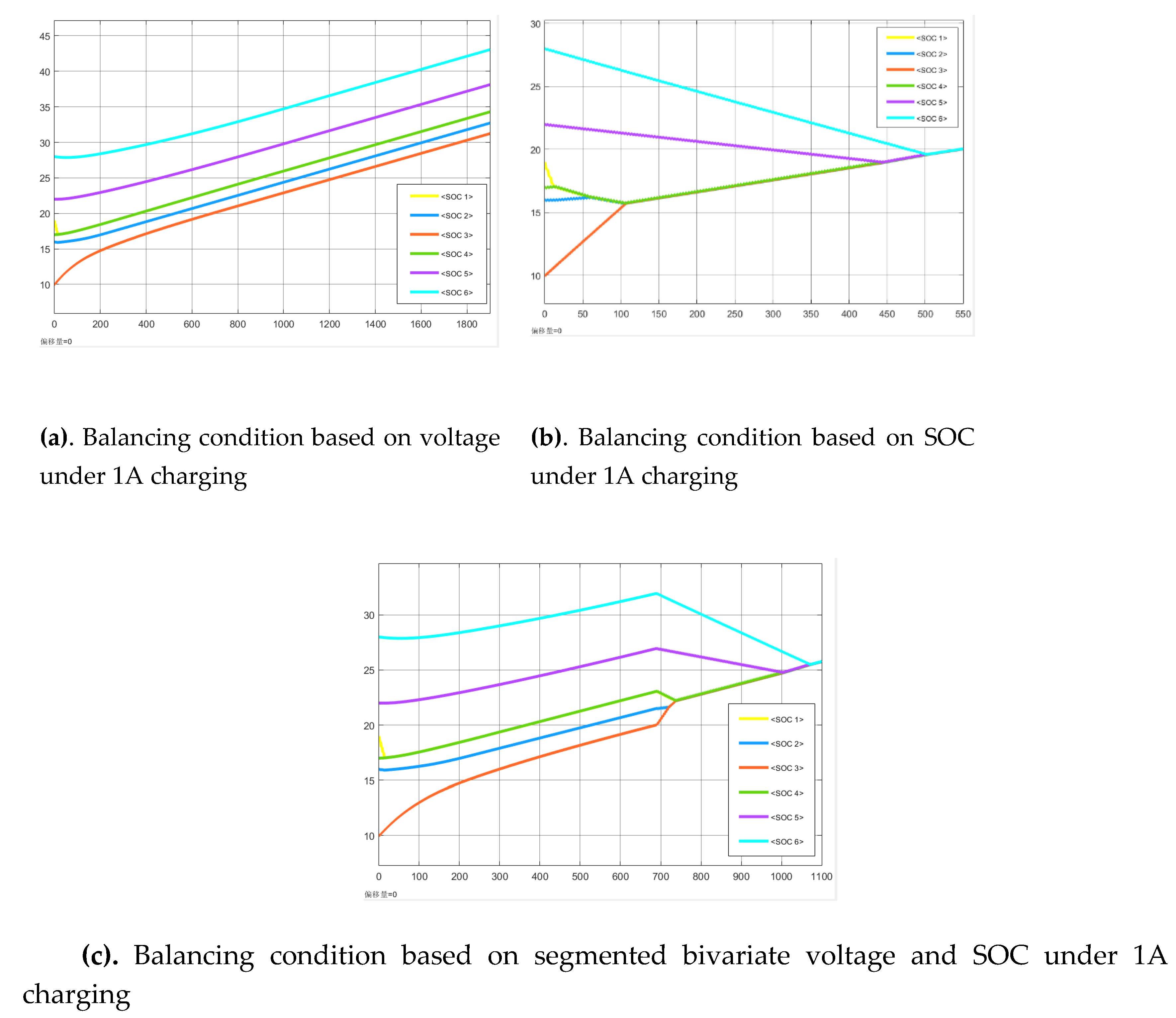
Figure 19.
Balancing results under 1A discharging condition.
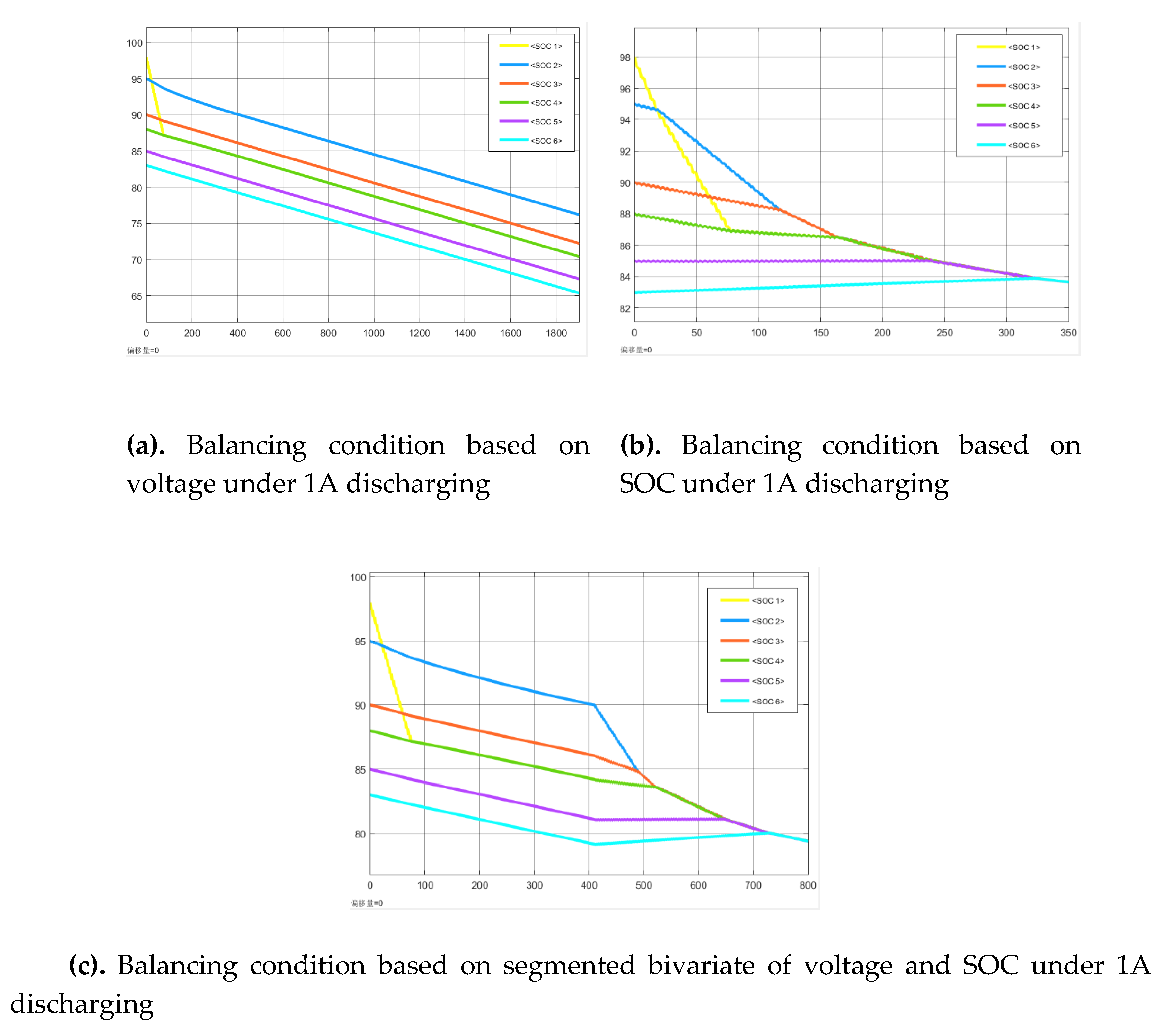

Table 1.
Comparison of Equilibrium Results for Various Equilibrium Topologies.
| Balancing topology | Resting (s) | 1A charging (s) | 1A discharging (s) |
| Traditional single-layer single inductor | 845 | 837 | 850 |
| Multi-inductors parallel type | 434 | 431 | 435 |
| Multiple inductor interleaving | 424 | 421 | 426 |
| "dichotomous" hybrid | 306 | 303 | 308 |
Table 2.
Comparison of Balancing Variables.
|
Balancing variable |
Advantages | Disadvantages |
| Voltage | High sampling accuracy, fast response, and simple control | Significant voltage fluctuations, challenging balancing control accuracy, prone to over-balancing and misbalancing |
| SOC | Can accurately characterize battery inconsistency | Limited real-time capability and high computational complexity |
Table 3.
Initial SOC of the battery.
| Unit (%) | Battery 1 | Battery 2 | Battery 3 | Battery 4 | Battery 5 | Battery 6 |
| Resting | 44 | 19 | 34 | 27 | 36 | 17 |
| charging | 19 | 16 | 10 | 17 | 22 | 28 |
| Discharge | 98 | 95 | 90 | 88 | 85 | 83 |
Table 4.
Comparison of balance results of different strategies.
| Balancing strategy | Resting (s) | 1A charging (s) | 1A discharging (s) |
| Voltage balancing strategy | Incomplete | Incomplete | Incomplete |
| SOC balancing strategy | 727 | 504 | 322 |
| Segmented bivariate balancing strategy |
956 | 1075 | 730 |
Disclaimer/Publisher’s Note: The statements, opinions and data contained in all publications are solely those of the individual author(s) and contributor(s) and not of MDPI and/or the editor(s). MDPI and/or the editor(s) disclaim responsibility for any injury to people or property resulting from any ideas, methods, instructions or products referred to in the content. |
© 2025 by the authors. Licensee MDPI, Basel, Switzerland. This article is an open access article distributed under the terms and conditions of the Creative Commons Attribution (CC BY) license (http://creativecommons.org/licenses/by/4.0/).
Copyright: This open access article is published under a Creative Commons CC BY 4.0 license, which permit the free download, distribution, and reuse, provided that the author and preprint are cited in any reuse.


