Submitted:
23 August 2025
Posted:
27 August 2025
You are already at the latest version
Abstract
The known liquid crystal photoalignment mechanisms variety is not exhaustive. We introduce a completely new concept of photoalignment of liquid crystals, which explains formation of anisotropic interaction and provides deep understanding of physical mechanisms behind the alignment effect of photo-induced hole dipoles in thin films of azo-dyes. The self-consistency condition establishing in the wet dye film is locked through intermolecular coordination bonding in the dry film, which stabilizes the electrical field of molecular dipoles and allowing photo-induced hole dipoles. Advanced photoalignment materials with state-of-art properties of high photosensitivity, strong anchoring with no birefringence and high chemical compatibility are developed for application in Pancharatnam-Berry phase liquid crystal photonics and display devices based on the new concept of photoalignment.
Keywords:
photoalignment
; photosensitivity
; strong anchoring
; intermolecular bonds
; hole dipoles
; mechanism
1. Introduction
Although many geometrical Pancharatnam-Berry phase liquid crystal (LC) devices are still in the R&D stage, its future large scale commercial application requires solution of technological bottlenecks on the side of LC photoalignment materials. Stability towards temperature and humidity, chemical compatibility, high anchoring and high photosensitivity are the essentials that significantly affect the yield and the cost. The photosensitivity of the photoalignment material is very hard to improve, as it is the main part of the chemical structure and the photoalignment mechanism.
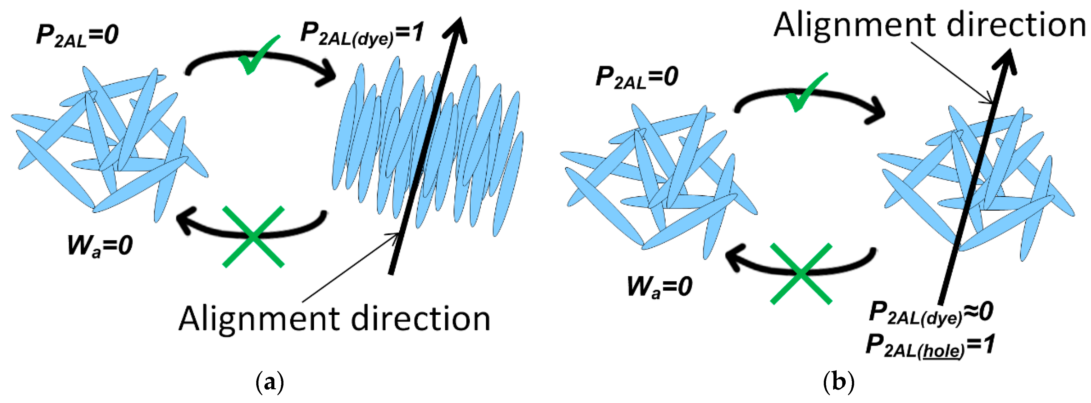
The well-known classical photoalignment mechanisms are based on one of the standard photoreactions types, such as photoisomerization, photodegradation or photo-crosslinking, have one or more typical inherent disadvantages: poor thermal stability, low photosensitivity, production of by-product, poor alignment performance and stability [1]. According to alternative well-studied azo-dye photoalignment mechanism of rotation diffusion (so called ‘diffusion model’) [2] the azo-dyes’ molecules undergo rotation under the action of linear polarized light forming anisotropic distribution of dye molecules in the alignment layer. The azo-dye molecules in the photoalignment layer are oriented in the direction perpendicular to the polarization plane of light exposure, forming the alignment direction (Figure 1a).
The in-plain LC alignment effect is measured in terms of the azimuthal anchoring energy Wa, which is determined for the case of the flat surface of the alignment layer [3] as the next:
where μLC, – the average dipole moment of nematic LC molecule, μAL – the dipole moment of the alignment layer molecule; P2LC and P2AL are the orientation order parameters P2 of the LC and the alignment layer, C – is the constant.
Theoretical study [2] estimates the requirement of 10 acts of photon absorption per each molecule for orientation of the dye molecules with high order parameter P2AL, which limits the photosensitivity of the rotation diffusion photoalignment mechanism.
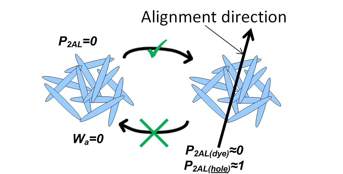
Recently the new photoalignment mechanism of photo-induced hole dipoles [4] have been reported, while its amazing possibilities are being explored. The main new difference is that dye molecules do not undergo molecular reorientation keeping low the dye order parameter under linear polarized light, which induces alignment direction perpendicular to the polarization of exposure with strong azimuthal anchoring of liquid crystal (Figure 1b).
Figure 1.
Concept schemes of liquid crystal photoalignment mechanisms based on: (a) Dye molecules ‘diffusion model’ of that requires 10 photons per 1 molecule; (b) ‘Photo-induced hole dipoles model’ that requires 1 photon per 2 molecules.
Figure 1.
Concept schemes of liquid crystal photoalignment mechanisms based on: (a) Dye molecules ‘diffusion model’ of that requires 10 photons per 1 molecule; (b) ‘Photo-induced hole dipoles model’ that requires 1 photon per 2 molecules.
The photoalignment mechanism is based on formation of reversible intermolecular bonds [5]; these are multiple coordination bonds between metal and oxygen atoms of the dyes’ molecules in the solid film [6]. Such bonding limits the freedom of molecular motion in the film, stabilizing spatial orientation of molecules and molecular dipoles from thermal disordering with thermal energy kT, but can be selectively released for the dye molecule having absorbed a photon with energy hν. The energy of each bond Ebonds is subject to the following condition:
where : k – Boltzmann constant, T – system temperature, h – Plank constant, ν –absorbed photon frequency.
2. Materials and Methods
The photoalignment material studied here is the azo dye AtA-2 [4]. The peculiarities of its molecular structure (Figure 2) are the side groups’ free rotation around N=N bonds and formation of O-K…O intermolecular coordination bonding.
The theoretical calculations have been carried out using the Gaussian 09 quantum chemical package [7]. The computations have been performed using the density functional theory (DFT) with the popular hybrid B3LYP functional at the basis set level of 6-31G(d). The gas phase ground state molecular geometries were fully optimized without imposing any molecular symmetry constraints for each configuration.
The photoalignment layer is the AtA-2 film obtained by wet process (Figure 3) from 0.5% AtA-2 solution in N,N-dimethylformamide (DMF). The film thickness depends on the coating conditions and is typically within the range of 10-20 nm. The first step is wet coating, which brings to formation of a wet film on the substrate. Next the soft baking for 2-5 min on the hot-plate at temperature 100-150°C is applied to remove the solvent and make the dry film, which is the photosensitive alignment layer. AtA-2 molecules of the dry film form intermolecular bonds that blocks molecular motion. Finally the linear polarized (LP) light exposure is used to form the liquid crystal photoalignment direction on the surface of the alignment layer perpendicular to the polarization direction.
Processing the dry film of AtA-2 dye with the humid air of 60% humidity at 25°C allows saturating the film with an aqueous solvent. It brings back the properties of the original wet film, releasing intermolecular bonds and enabling molecular motion. The AtA-2 film was placed into the box with humidity and temperature control and kept for 5 min of humid air treatment. It is safe to the photoalignment layer, as the dye structure (Figure 2) does not have aqua-sensitive groups, e.g.–NaSO3 that forms crystal hydrates.
Hot-plate baking and humid air treatment are the methods for converting wet film into dry film and vice versa, which are also the methods for deactivation and activation of the self-consistency condition inside the AtA-2 dye film.
The dye film characterization method is the measurement of its dichroic ratio (DR), which is related to orientation of linear dye molecules in the film. The azo dye films may possess property of the photoinduced absorption anisotropy [2]. DR is determined by linear polarized light absorptions measured parallel, Aparal, and perpendicular, Aperp, to the direction of LP exposure of the film:
3. Results
3.1. Formulation of the Photoalignment Mechanism: Photo-Induced Hole Dipoles
The wet azo-dye film is coated on top of the substrate. Such wet film lacks the reversible intermolecular bonding due to significant content of the residual solvent. Thus a dipole moment of a dye molecule in the wet film is emerged into the electrical mean-field of its neighboring molecules, while the molecular dipoles are free to move and rotate in order to minimize the potential energy of interaction between the dipoles. Such behavior is also known as the self-consistency condition, when the local electric mean-field that is the sum of fields of all dye molecules in the film is compensated:
where is the field of i-th dye molecule at the r coordinate position inside the dye film that contains N dye molecules.
Next the hot plate baking is used to remove the solvent and obtain a dry film with intermolecular bonding that restricts the molecular motion and disables the self-consistency condition. However, the molecular orientation distribution, established prior in the wet film with respect to equation 4, is maintained in the dry film.
Let’s study the field of the N-th dye molecule, located at the rN coordinate position: – it is the field of the dipole, defined by the dye molecule with dipole moment . Consider the Equation 4 at the rN coordinate position:
Define the sum of the field of N-1 dye molecules at the rN coordinate position, where the N-th dye molecule is located, as the field of the hole dipole, located at the rN coordinate position:
– is the field of the hole dipole with dipole moment . See Equations 5 and 6, obtain the next formula:
According to Equation 7 the electrical field of the photo-induced hole dipole equals to the inverted field of the dye molecule. That means that the magnitude of the hole dipole moment equals to the dipole moment of the dye molecule (Figure 4), while dipole moments’ directions are reciprocally opposite: .
3.2. Theoretical Study of AtA-2 Photoalignment Effect
We performed quantum-mechanical calculations that explain how new photoalignment mechanism generates ordered dipole moments, required for LC alignment by flat surface [3], without reorientation of dye molecules. Figure 5 shows possible three stable configurations of the AtA-2 dye molecule. There are small differences between full energies of the three molecular configurations within ±3 kJ/mol that is possible for thermal energy at film forming temperature over 360K. Due to molecular symmetry consideration Figure 5a is more preferable. Next the general molecular dipole moments were analyzed. According to modelling results the optimized AtA-2 structures of Figure 5a, 5b and 5c possess strong dipole moment of 6.1D, 27D and 16D, correspondingly.
The AtA-2 configuration Figure 5a is of the special interest since it allows inversion of dipole moment direction in case of the flip of the central dibenzothiophene group, while keeping unchanged the orientation of molecular π-conjugated system of AtA-2 molecule that is responsible for anisotropic absorption of linear polarized light. The AtA-2 molecules inside the dry film are mutually fixed with intermolecular K…O coordination bonds, which stabilize the electrical field that is described as the hole dipole at the location of each dye molecule according to Equations 6 and 7 (Figure 4).
The interaction of the hole dipole with the dye molecule dipole inside the dry film can be modelled as a dimer – two dye molecules with opposite orientation of its’ dipole moments, shown on Figure 6a and Figure 6c, such dimer configurations possess near zero values of the dipole moment, correspondingly, 0.07D and 0.02D.
The hole dipole field is represented by the field of a dye molecule, while formation of intermolecular bonds between two dye molecules of the dimer models the bonding of the dye molecule inside the dry film. The main difference of the dimer model from the real case is that the actual hole dipole is not photosensitive and cannot absorb photon. Thus in this dimer model only one molecule of the pair is photosensitive; and the hole dipole orientation is not changed, when the photosensitive dye molecule of the dimer pair absorbs a photon.
The absorption probability of linear polarized light depends on the angle between the light polarization and the absorption oscillator (long axis of the π-conjugated system) of the dye molecule [2].
On having absorbed a photon the dye molecule receives energy that is sufficient for breaking of coordination bonding and/or performing flip of the central dibenzothiophene group through rotation around both NN bonds, when the position of the side groups is fixed via intermolecular bonding of K...O coordination bonds (Figure 6). Once the flip is committed the dipole moment of the dye molecule inverts its orientation and becomes parallel to the local hole dipole direction without a change of the dye molecule orientation. Thus the spatial position and orientation of the dimer is preserved, while its dipole moment increases in direction close to perpendicular to the absorption oscillator of the dye molecule. Figure 6b and Figure 6d show such dimer configurations with the photo-induced dipole moment of 16.01D and 12.25D, correspondingly.
We conclude that the ‘dimer model’ reveals the photoalignment mechanism of the photo-induced hole dipoles, that gives the physically consistent grounds for formation of hole dipole moments with high order parameter in the dry film of AtA-2 dye and with low molecular order upon exposure with low dose of linear polarized light.
3.3. Experimental Study of AtA-2 Photoalignment Effect: Humid Air Treatment
According to the mean-field theory developed for description of the nematic liquid crystals [10], rod-like molecules with permanent dipole moment possess self-orientation of molecules within the short-range along the specified direction (known as director), once the molecular dipoles are oriented with the order parameter P2, which is equal to or larger than the certain value Smin, due to resultant interaction of molecules. Such self-orientation of molecules and its permanent dipole moments occurs due to minimization of the interaction energy of the material in the nematic phase, causing increase of P2 to the value S, which is typically within the range of 0.45-0.8 and subject to the temperature. However, if the Smin value is not reached by the molecular order due to high temperature disordering, then the intermolecular interaction minimizes P2 to S, which is equal to zero, known as isotropic phase. The temperature dependent change of the P2 below the Smin value is known as nematic to isotropic phase transition, while the material is called ‘thermotropic LC’.
Mean-field approach based on interaction of ordered dipoles is rather general and describes self-orientation of rod-like units with dipole moment. The temperature is not the only factor that can change the order parameter of the dipole moments, ‘lyotropic LC’ are subject to the solvent concentration, while ‘electrotropic LC’ are subject to the electrical field.
In the case of AtA-2 film the rod-like dye molecule has permanent dipole moment, while the order parameter of the dye dipoles is subject to the LP light exposure dose. The experimental verification requires photoalignment layer treatment with humid air, which temporary releases the bonding allowing molecular movement to minimize the potential by molecules’ orientation adjustment and unlocking the self-consistency condition (Eq.3) on turning the dry film into the wet film.
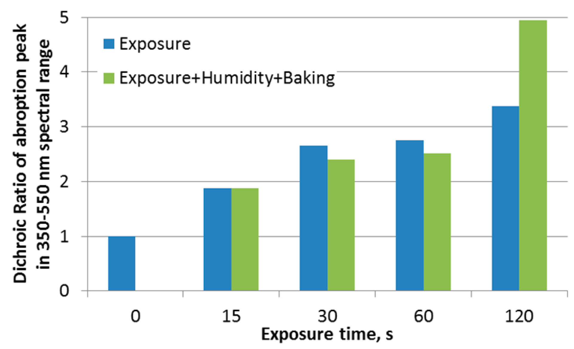
The AtA-2 dye photoalignment layer was coated on glass substrate and exposed with polarized light of 450nm LED. The dichroic ratios of the AtA-2 film were measured right after the exposure. Next the substrate was placed in the closed box and exposed to wet air (60% humidity at 25°C) for 5 min. The hot-plate baking at 110°C for 5 min was applied after the humid air treatment in order to dry the AtA-2 film, and the dichroic ratios of the dry AtA-2 film were measured again and compared to the initial values (Figure 7). Then two substrates of the AtA-2 photoalignment layer were assembled into 90°deg twist LC cell with 5 mkm cell-gap and filled with E7 liquid crystal mixture. Such LC cells were used for azimuthal anchoring energy measurements, that confirmed >10-4 J/m2 for exposure times of 15, 30, 60 and 120 s with 450nm LED light intensity of 40 mW/cm2.
4. Discussion
The experiment with humid air treatment reveals that two photoalignment mechanisms are observed. The photo-induced hole dipoles mechanism occurs for exposure times below 15 s, when molecular ordering is low and dichroic ratio is not changed upon humid air treatment. The times of 30-60 s are the transition range, when the dichroic ratio decreases upon humid air treatment, i.e. isotropization of molecular orientation is observed. At 120s time molecular reorientation reaches certain transitional order parameter value, Smin, when the mean-field interaction of nematic phase prevails [10] leading to dichroic ratio increase upon humid air treatment.
The main intrigue is that we have shown in experiment that polarized light exposure of AtA-2 layer gives strong azimuthal anchoring energy >10-4 J/m2 using short exposure time below 15s and without molecular ordering due to photoalignment mechanism of photo-induced hole dipoles.
The new concept of highly photosensitive photoalignment that provides strong azimuthal anchoring of liquid crystal and has no birefringence of alignment layer is presented. It is based on photo-induced hole dipoles photoalignment mechanism new photoalignment materials allow film coating either from DMF solvent for AtA-2 dye or H2O:IPA solvent for AmA-2522 dye, and require low expose dose of 12-40 mJ/cm2, to provide azimuthal anchoring energy of ~10-4 J/m2, which ideally meets the demand of Pancharatnam-Berry phase LC photonic devices.
5. Conclusions
We conclude that the ‘dimer model’ reveals the photoalignment mechanism of the photo-induced hole dipoles, that gives the physically consistent grounds for formation of hole dipole moments with high order parameter in the dry film of AtA-2 dye and with low order parameter of dye molecules upon exposure with low dose of linear polarized light. It explains the photoinduction of strong anisotropic long range dipole-dipole interaction inside the dye film with near isotropic molecular order, ensuring low anisotropy of film’s optical properties, i.e. absorption and refractive index.
It was experimentally verified that polarized light exposure of AtA-2 layer gives strong azimuthal anchoring energy >10-4 J/m2 using exposure dose above >40 mJ/cm2 of polarized 450nm LED light and exposure times 1-15 s. High photosensitivity of AtA-2 photoalignment layer is subject to the photoalignment mechanism of photo-induced hole dipoles, which gives physically consistent explanation of polarized light induction of strong LC photoalignment properties of azo-dye film without molecular ordering of the dye molecules for non-birefringent photoalignment layer.
Author Contributions
Conceptualization, Al.M. and I.K.; methodology, Al.M.; software, I.K.; validation, An.M., V.S. and I.K.; formal analysis, An.M.; investigation, V.S.; resources, D.D.; data curation, Al.M.; writing—original draft preparation, Al.M.; writing—review and editing, Al.M.; visualization, I.K.; supervision, Al.M.; project administration, Al.M.; funding acquisition, Al.M. All authors have read and agreed to the published version of the manuscript.
Funding
This research received no external funding.
Data Availability Statement
The data for evaluation of the conclusions are presented in the paper.
Acknowledgments
The authors acknowledge support from the European Union grant contract NDICI-GEO-NEAR/ 2022/434-092-0036; EU Contribution Agreement No. ENI/2021/423-841, SALT project, service contract No. 2025/4-3-105.
Conflicts of Interest
The authors declare no conflicts of interest.
Abbreviations
The following abbreviations are used in this manuscript:
| DFT | Density functional theory |
| DMF | Dimethylformamide |
| DR | Dichroic ratio |
| IPA | Isopropanol |
| LC | Liquid crystals |
| LED | Light emitting diode |
| LP | Linear polarization |
References
- Xi, X.; Yan, C.; Shen, L.Z.; Wang, Y.; Cheng, P. Liquid crystal photoalignment technique: Basics, developments, and flexible/stretchable device applications. Materials Today Electronics 2023, 6, 100069. [Google Scholar] [CrossRef]
- Chigrinov, V.; Pikin, S.; Verevochnikov, A.; Kozenkov, V.; Khazimullin, M.; Ho, J.; Huang, D.D.; Kwok, H.S. Diffusion model of photoaligning in azo-dye layers. Phys. Rev. E 2004, 69, 061713. [Google Scholar] [CrossRef] [PubMed]
- Muravsky, A.A.; Murauski, A.A. Q&A of liquid crystal alignment: theory and practice, Front. Soft Matter 2024, 4, 1382925. [Google Scholar] [CrossRef]
- Muravsky, A.A.; Murauski, A.A.; Kukhta, I.N. Photoinduced hole dipoles’ mechanism of liquid crystal photoalignment, Appl. Opt. 2020, 59, (17), 5102–5107. [Google Scholar] [CrossRef]
- Muravsky A., Next Generation of Photoalignment: Reversible Intermolecular Bonds; VDM Verlag, Germany, 2009; pp. 21-39. ISBN 978-3639159127.
- Mikulich, V. S., Muravsky, A. A., Murauski, A. A., Kukhta, I. N., Agabekov, V. E., Altamimi, R. Photoalignment dynamics of azo dyes series with different coordination metals. J. Soc. Inf. Displ. 2014, 1, 29–34. [CrossRef]
- Frisch, M. J. et al. Gaussian 09, Revision D 01, Gaussian, Inc., Wallingford, CT, 2009.
- Konovalov, V.A.; Muravski, A.A.; Yakovenko, S.Y.; Pelzl, J. P-25: an accurate spectral method for measuring twist angle of twisted cells with rubbed and grooved surfaces. SID Symp.Dig.Tech.Pap. 2000, 31, 620–623. [Google Scholar] [CrossRef]
- Muravsky, A.; Murauski, A. 40.3: Effect of Birefringent Alignment Layer on Azimuthal Anchoring Energy Measurement. J. Soc. Inf. Displ. 2021, 52(S2), 497–499. [Google Scholar] [CrossRef]
- Tough R.J.A., Bradshaw M.J., The determination of the order parameters of nematic liquid crystals by mean field extrapolation, J. Physique 1983, 44 (3), 447. [CrossRef]
Figure 2.
Molecular structure of AtA-2 dye.
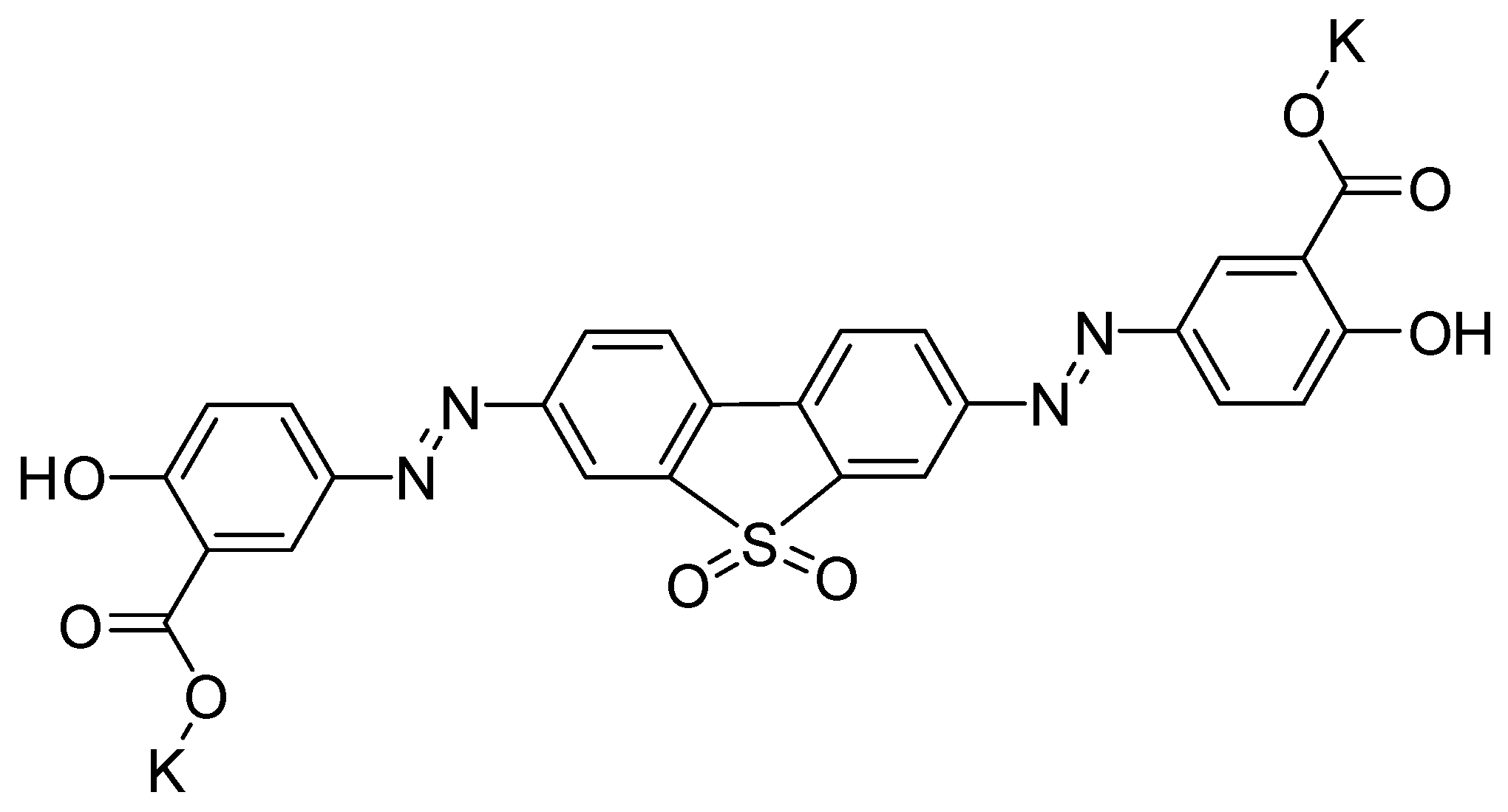
Figure 3.
Process flow of the AtA-2 photoalignment layer.
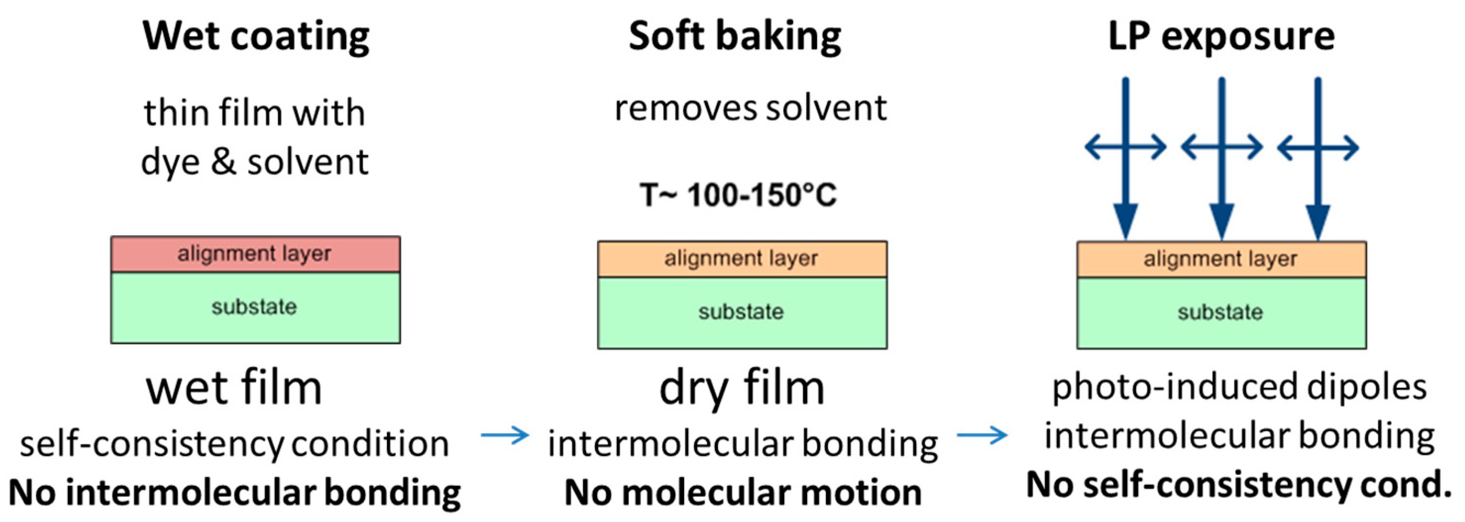
Figure 4.
Fulfilment of self-consistency condition inside the dry film of AtA-2 dye at rN coordinates position by a dye molecule with dipole moment μdye and a hole dipole with dipole moment μhole.
Figure 4.
Fulfilment of self-consistency condition inside the dry film of AtA-2 dye at rN coordinates position by a dye molecule with dipole moment μdye and a hole dipole with dipole moment μhole.
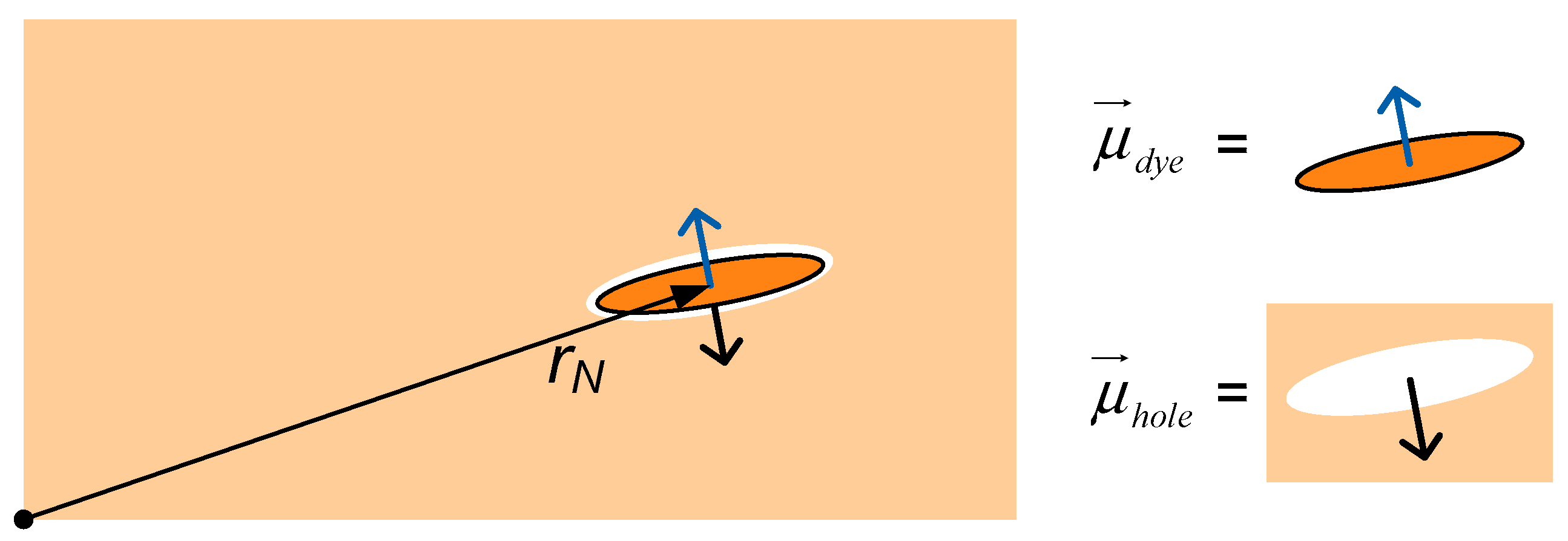
Figure 5.
Configurations of AtA-2 dye molecule with dipole moments and differences between its full energy levels: (a) 6.1D, ΔE= 0 kJ/mol; (b) 27D, ΔE= +3 kJ/mol; (c) 16D, ΔE= -2 kJ/mol.
Figure 5.
Configurations of AtA-2 dye molecule with dipole moments and differences between its full energy levels: (a) 6.1D, ΔE= 0 kJ/mol; (b) 27D, ΔE= +3 kJ/mol; (c) 16D, ΔE= -2 kJ/mol.
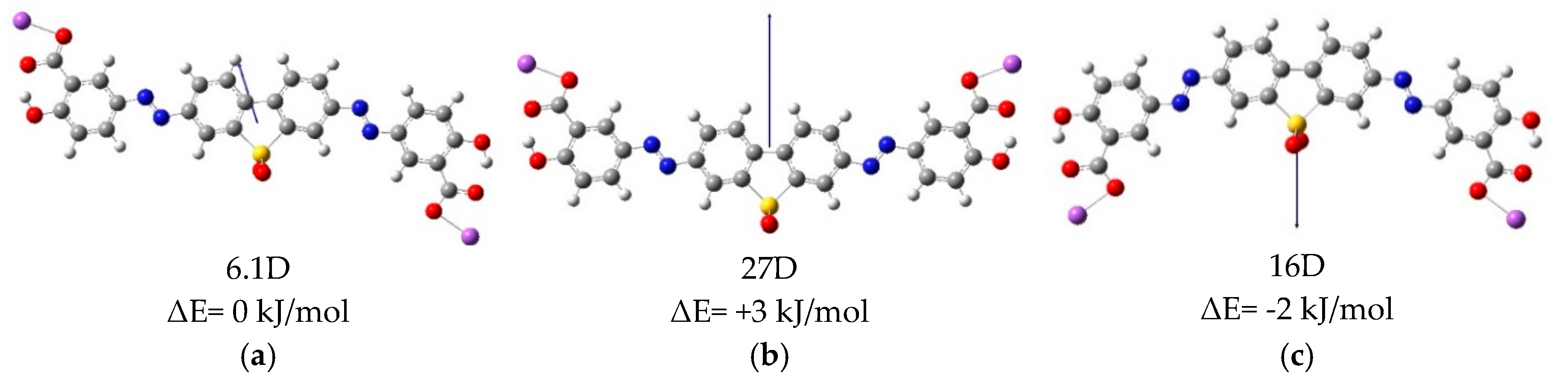
Figure 6.
Dimers configurations of two AtA-2 molecules with opposite (a,c) and co-directional (b,d) orientation of its’ dipoles and corresponding dipole moments: (a) 0.07D, (b) 16.01D, (c) 0.02D and (d) 12.25D.
Figure 6.
Dimers configurations of two AtA-2 molecules with opposite (a,c) and co-directional (b,d) orientation of its’ dipoles and corresponding dipole moments: (a) 0.07D, (b) 16.01D, (c) 0.02D and (d) 12.25D.
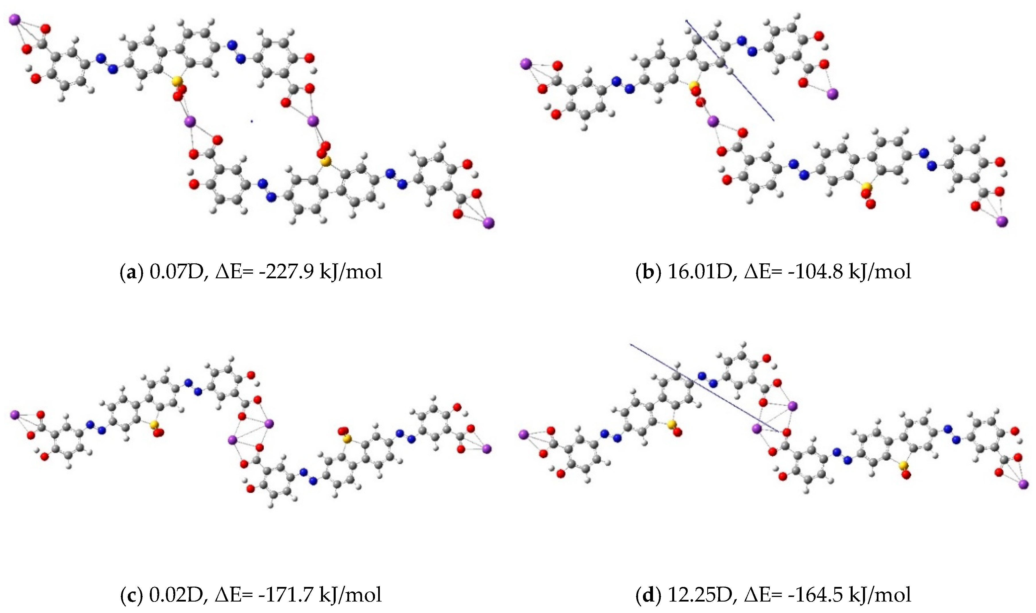
Figure 7.
Dichroic Ratio of AtA-2 photoalignment layer measured after light exposure (blue) and after humid air treatment (green).
Figure 7.
Dichroic Ratio of AtA-2 photoalignment layer measured after light exposure (blue) and after humid air treatment (green).
Disclaimer/Publisher’s Note: The statements, opinions and data contained in all publications are solely those of the individual author(s) and contributor(s) and not of MDPI and/or the editor(s). MDPI and/or the editor(s) disclaim responsibility for any injury to people or property resulting from any ideas, methods, instructions or products referred to in the content. |
© 2025 by the authors. Licensee MDPI, Basel, Switzerland. This article is an open access article distributed under the terms and conditions of the Creative Commons Attribution (CC BY) license (https://creativecommons.org/licenses/by/4.0/).
Copyright: This open access article is published under a Creative Commons CC BY 4.0 license, which permit the free download, distribution, and reuse, provided that the author and preprint are cited in any reuse.


