Submitted:
19 August 2025
Posted:
20 August 2025
You are already at the latest version
Abstract
This study presents a computational investigation into the design of triphenylamine-based donor chromophores incorporating 2-(1,1-dicyanomethylene)rhodanine as the acceptor unit. Three molecular architectures (System-1 to System-3) were developed by introducing distinct thiophene-derived π-bridges to modulate their electronic and optical characteristics for potential application in bulk heterojunction organic solar cells (OSCs). Geometrical optimizations were performed at the B3LYP/6-31+G(d,p) level, while excited-state and absorption properties were evaluated using TD-DFT with the CAM-B3LYP functional. Frontier orbital analysis revealed efficient charge transfer from donor to acceptor moieties, with System-3 showing the narrowest HOMO–LUMO gap (1.96 eV) and the lowest excitation energy (2.968 eV). Charge transport properties, estimated from reorganization energies, indicated that System-2 exhibited the most favorable balance for ambipolar transport, featuring the lowest electron reorganization energy (0.317 eV) and competitive hole mobility. Photovoltaic parameters calculated with PC61BM as acceptor predicted superior Voc, Jsc, and fill factor values for System-2, resulting in the highest theoretical power conversion efficiency (10.95%). These findings suggest that π-bridge engineering in triphenylamine-based systems can significantly enhance optoelectronic performance, offering promising donor materials for next-generation OSC devices.
Keywords:
molecular systems
; reorganization energy
; density functional theory
; UV-Vis absorption
1. Introduction
The growing global energy demand, coupled with the environmental impact of fossil fuel dependence, has intensified the search for clean, renewable alternatives [1,2,3]. Among various photovoltaic technologies, organic solar cells (OSCs) have attracted significant interest due to their lightweight nature, mechanical flexibility, solution-processability, and potential for low-cost fabrication [4,5,6,7]. Although crystalline silicon has long dominated the solar market—offering efficiencies above 47% under concentration—its rigidity, high production cost, and limited tunability of electronic properties motivate the exploration of organic-based counterparts [8,9,10].
In recent years, molecular engineering has emerged as a powerful strategy to overcome the intrinsic limitations of OSCs, particularly in enhancing light harvesting, charge mobility, and reducing energy losses [11]. Donor--acceptor (D––A) architectures are especially appealing because their modular design enables fine-tuning of optoelectronic properties through modifications of donor units, acceptor groups, or –bridges. Triphenylamine (TPA) derivatives have been widely explored as donor moieties due to their strong electron-donating ability [12,13], high hole mobility, and structural versatility. When covalently linked to acceptor groups such as 2-(1,1-dicyanomethylene)rhodanine, TPA-based systems can form efficient push–pull structures that promote charge separation and suppress recombination [14].
In this work, three new A––D––A chromophores (System-1 to System-3) were theoretically designed by varying the –bridge composition. Density functional theory (DFT) and time-dependent DFT (TD-DFT) calculations were employed to examine how these structural modifications influence electronic structure, optical absorption, charge transport, and photovoltaic performance, with the aim of identifying promising donor materials for high-efficiency bulk heterojunction OSCs.
2. Chromophores and Computational Methods
In this work, we consider an organic molecular system as depicted in Figure 1. Each molecule is classified into three fragments: a central unit acting as an electron donor, molecular bridges that facilitate charge transfer, and terminal groups serving as electron acceptors. In these systems, we use the structure of 4-Hexyloxy-Triphenylamine (TPA) as the electron donor fragment, which consists of a triphenylamine core connected to the electron acceptor fragment 2-(1,1-Dicyanomethylene)-1,3-thiazolene-4 (DCR) through molecular bridges (B). Different molecular bridges are employed for the design of new push-pull chromophores, such as 2,5-Dimethylthiophene (B1), 4,4”-Dihexyl-2,2’:5’,2”-Terthiophene (B2), and 2-(9,9-Dihexyl-9H-Fluoren-2-yl)hexylthiophene (B3), to create the systems (System-1), (System-2), and (System-3), respectively. The choice of molecular bridges is based on their ability to enhance -conjugation and facilitate efficient charge transfer between the donor and acceptor units. The incorporation of 2,5-dimethylthiophene and fluorenyl-thiophene bridges is expected to reduce the energy gap and improve electron mobility.
To determine the geometry of the most stable conformations, the molecular systems were geometrically optimized to reveal their ground state () structures using density functional theory (DFT) with the hybrid functional B3LYP [15] and the 6-31+G(d,p) basis set, as implemented in Gaussian 09 [16]. The energies of the molecular systems were calculated based on these optimized geometries. The excited states of the molecules and the UV-Vis spectra reported here were simulated using time-dependent density functional theory (TD-DFT) with the CAM-B3LYP/6-31+G(d,p) basis set. Both the gas phase and the solvent environment ethanol (EtOH) were considered, with the solvent effects modeled using the conductor-like polarization continuum model (C-PCM) [17,18]. Additionally, we derived various properties from the computational results, such as the highest occupied molecular orbitals (HOMOs), lowest unoccupied molecular orbitals (LUMOs), energy gap, reorganization energy, and excitation energy.
3. Results and Discussion
3.1. Frontier Molecular Orbital (FMO) Analysis
To explore the influence of -bridge variations on the electronic structure, the frontier molecular orbitals (FMOs) of System-1, System-2, and System-3 were examined at their optimized geometries. TD-DFT calculations were employed to identify electronic transitions relevant to charge-transfer (CT) processes. In all three systems, the highest occupied molecular orbital (HOMO) is mainly localized on the electron-donating TPA core, while the lowest unoccupied molecular orbital (LUMO) is concentrated on the rhodanine-based acceptor units sa see in in Figure 2. This spatial separation supports efficient donor-to-acceptor CT [19]. Intermediate orbitals (HOMO–1, LUMO+1) show varying degrees of delocalization across the —bridges, with System-2 and System-3 displaying stronger bridge participation compared to System-1.
The HOMO–LUMO gaps in ethanol were calculated as 2.13 eV (System-1), 1.97 eV (System-2), and 1.96 eV (System-3) are shown in Table 1, consistent with the expectation that extended -conjugation and electron-withdrawing substituents reduce the band-gap [20,21]. Notably, the fluorenyl-thiophene bridge in System-3 produces the smallest gap, while System-2 achieves a comparable reduction through terthiophene insertion. These results indicate that -bridge engineering effectively tunes the energy alignment and spatial orbital distribution, factors directly impacting exciton dissociation efficiency and charge transport in OSC applications.
3.2. Electronic Absorption Spectral
The optical response of the three designed chromophores was evaluated to assess the role of -bridge modifications on light-harvesting capability. TD-DFT simulations at the CAM-B3LYP/6-31+G(d,p) level were carried out in both gas phase and ethanol, with solvent effects modeled via CPCM.
In ethanol, the main absorption bands span from 417.69 nm to 525.55 nm as shown in Figure 3. System-2 exhibits the most red-shifted maximum ( nm), attributable to enhanced conjugation through its terthiophene bridge, which facilitates intramolecular charge transfer (ICT) from the TPA donor to the rhodanine acceptor. In contrast, System-3 displays a hypsochromic shift with a of 417.69 nm, indicating a slightly higher excitation energy despite its narrow HOMO–LUMO gap.
Multiple absorption peaks are observed in each system. For System-2, the primary band corresponds to HOMO→LUMO transitions, while secondary peaks in the UV region arise from excitations involving deeper occupied orbitals and higher unoccupied states. The calculated oscillator strengths () suggest that System-2 has the highest light-harvesting efficiency (LHE), exceeding 99.9%, followed closely by System-3, with System-1 being comparatively lower; The and other parameters are summarized in Table 2.
Overall, the results highlight that -bridge length and electronic structure strongly influence absorption wavelength and intensity, with System-2 offering the most favorable profile for OSC donor applications due to its broad and intense visible-light absorption.
3.3. Ionization Potential and Electron Affinity
Ionization potential (IP) and electron affinity (EA) are key descriptors for evaluating charge injection and extraction in organic photovoltaic devices [22]. Molecules with lower IP values generally facilitate hole injection from the donor material, while higher EA values promote electron capture by the acceptor [23].
From our calculations in ethanol, System-3 exhibits the lowest IP (5.198 eV), indicating that it requires the least energy to remove an electron from the HOMO, thereby favoring hole extraction. System-2 follows closely, while System-1 presents the highest IP, suggesting less efficient hole generation. In terms of EA, all three systems show values above 3.28 eV, with System-3 achieving the highest (3.374 eV), reflecting strong electron-accepting capability.
These results suggest that -bridge engineering not only alters the energy gap but also tunes the energy levels to improve charge-transfer balance. In particular, the combination of low IP and high EA in System-3 could support efficient bidirectional charge transport, although other parameters—such as reorganization energy—must also be considered to determine the most suitable candidate for OSC applications.
3.4. Reorganization Energy
Charge transport efficiency in organic semiconductors depends strongly on two microscopic factors: the electronic coupling between donor and acceptor fragments, and the reorganization energy () associated with structural relaxation during charge transfer [24,25]. Lower values indicate that less structural rearrangement is required, favoring higher mobility.
The intramolecular reorganization energy can be estimated for electrons (electron reorganization energy, ) and for holes (hole reorganization energy, ), and can be expressed by the following equation [26]:
where and represent the anionic and cationic energies, respectively, used to describe the ground state energy of a neutral compound in these equations. At the single-point ground state, corresponds to the energy of the neutral molecule, while and represent the single-point ground state energies of the anion and cation after optimization. and are the ground state energies for the optimized anion and cation, respectively.
We evaluated both electron () and hole () reorganization energies in gas phase and ethanol. In the solvent environment, all systems display reduced values compared to vacuum, indicating that ethanol stabilizes charge transfer processes. System-2 presents the lowest (0.142 eV in ethanol, see Table 3), suggesting excellent electron transport potential, while System-3 has the lowest (0.198 eV), indicating superior hole mobility. System-1 shows balanced but slightly higher values for both carriers.
Interestingly, the terthiophene bridge in System-2 promotes efficient electron transfer, whereas the fluorenyl-thiophene bridge in System-3 favors hole conduction. The relatively small difference between and in System-2 suggests ambipolar behavior, which can be advantageous in bulk heterojunction OSC architectures. Overall, these findings confirm that targeted modification of the -bridge segment is an effective strategy to optimize carrier transport pathways, allowing the design of donor materials tailored for specific charge mobility requirements in photovoltaic devices.
3.5. Molecular Electrostatic Potential
To visualize how electronic charge is distributed within each chromophore, molecular electrostatic potential (MEP) maps were generated from the optimized geometries. These surfaces provide insight into regions susceptible to electrophilic or nucleophilic interactions, as well as the internal charge separation between donor and acceptor units [27]. In the three systems, the strongest negative potentials (depicted in red) are localized over the rhodanine-based acceptor termini as can be seen in the Figure 4, reflecting the high electron density associated with oxygen, nitrogen, and sulfur atoms in these regions. Conversely, positive potential zones (blue) are concentrated around the triphenylamine donor cores and parts of the -bridges, consistent with their electron-donating character.
Comparatively, System-2 shows more extensive negative potential regions than System-1 and System-3, indicating enhanced electron-withdrawing ability across the acceptor moieties. This distribution supports more effective intramolecular charge transfer, which correlates with its favorable photovoltaic performance. The MEP analysis confirms that -bridge composition modulates not only electronic energy levels but also the spatial arrangement of charge density, both of which are critical for optimizing the interaction between donor and acceptor phases in bulk heterojunction OSCs.
4. Photovoltaic Properties
In organic photovoltaic (OPV) technology, the most efficient cells are bulk heterojunction (BHJ) devices, as BHJ-based organic solar cells (OSCs) offer a promising future for economically converting solar energy into electricity, surpassing conventional silicon solar cells [28,29]. This is due to their low-temperature manufacturing process, light weight, flexibility [9,30], and their power conversion efficiency (PCE) exceeding 19% [6]. Although the PCE of OPV cells has improved significantly, there is still considerable work to be done before they achieve commercial viability, especially when compared to the 25.2% PCE of perovskite-based thin film solar cells [31]. Further improvements are necessary to optimize the IP performance. The PCE is directly dependent on the open-circuit voltage (), the short-circuit current density (), the fill factor (), and the incident solar energy. None of these four components can be overlooked in material design if better PCE values are to be achieved. In general, is related to the energy difference between the HOMO of the donor material and the LUMO of the acceptor material, and is also influenced by carrier generation and recombination rates, as well as tail energy states or trap states [32].
4.1. Open Circuit Voltage () Investigation
The open-circuit voltage () is a critical factor in determining the efficiency of organic solar cells, as it represents the maximum voltage a device can deliver when no current flows [33,34]. In donor–acceptor bulk heterojunctions, is primarily governed by the energy difference between the HOMO of the donor and the LUMO of the acceptor as seen in the Figure 5, offset by energy losses from charge recombination and other processes [35,36,37]. Theoretical values for the examined OSC systems are calculated using the equation reported by Scharber et al.[9], and the results are presented in Table 3.
Here, e is the elementary charge, and a value of V is a typical loss in bulk heterojunction solar cells. Using the simulated value of for the lowest unoccupied molecular orbital (LUMO) energy of PC61BM in this work, the analysis can proceed.
Here, PC61BM was used as the reference acceptor to estimate for the three designed systems. The calculated values are presented in Table 3 range from 1.03 V (System-3) to 1.32 V (System-1), all exceeding the typical 1.0 V threshold considered beneficial for efficient devices. System-1 achieves the highest , likely due to its relatively deeper HOMO level, while System-2 offers a balanced trade-off between and other photovoltaic parameters. Energy offsets () between donor and acceptor LUMO levels were also assessed and found to be above 0.3 eV in all cases, ensuring sufficient driving force for exciton dissociation. This alignment supports effective charge transfer at the donor–acceptor interface, a prerequisite for achieving high short-circuit currents and overall device performance.
4.2. Fill Factor (FF)
The PCE and other photovoltaic properties of organic solar cells (OSCs) can also be evaluated using an important parameter, the Fill Factor (FF). In practice, multiple physical mechanisms influence the FF, leading to various models proposed for its estimation [38,39]. These models are generally based on the current-voltage relationship, but differ in their assumptions regarding the causes and values of shunt and series resistances. The FF is typically expressed as a function of . The fill factor for molecular compounds can be calculated using Equation (4) [40]:
where is an adjustable factor for different solar cell technologies. For example, and provide the best fit for the upper limits of the FF measured in excitonic and non-excitonic solar cells, respectively, as indicated by Alharbi et al. [40]. In this equation, represents the open-circuit voltage, T is the system temperature (300K), and denotes the Boltzmann constant.
Using the calculated and values in conjunction with estimated resistive losses, the FF for the three systems was predicted within the range of 0.74 – 0.78 are summarized in Table 4. System-2 achieved the highest FF (0.78), followed closely by System-1, while System-3 showed a slightly lower value. The superior FF of System-2 is consistent with its favorable reorganization energies and balanced ambipolar transport, which likely reduce charge recombination and improve carrier extraction efficiency. Although the FF values across the systems are relatively close, small variations in molecular packing and charge mobility—dictated by -bridge composition—can lead to measurable performance differences in experimental devices. These trends underscore the importance of optimizing not only energy levels and absorption but also transport properties to maximize photovoltaic output.
4.3. Short-Circuit Current Density ()
Current-voltage density characteristics (J–V) are essential for analyzing voltage loss, based on the values of open-circuit voltage () and short-circuit current density (). The most accurate way to determine is to account for the spectral shape of sunlight, as both the intensity and spectral distribution depend on various factors, such as the calibration cell’s spectral response, the characteristics of the OSC medium, and the angle above the horizon. This approach allows defining a standard power spectrum, [41,42]. Therefore, can be calculated using the following expression [43,44,45]:
where h is Planck’s constant, c is the speed of light in a vacuum, represents the band gap of the hole-transporting material in the active layer of the device, and is the external quantum efficiency, assumed to be 80% for this study [9,24].
The values of and PCE for System-1 to System-3 are presented in Table 4. The values range from 9.52 to 12.21 mA/cm2, with the highest value observed for System-2, which also exhibits the highest PCE of approximately 10.95%. This study shows that, concerning the PCE of the systems considered and taking System-1 as a reference, the inclusion of thiophene rings as molecular bridges in System-2 enhances the PCE. However, incorporating dibenzothiophene in System-3 leads to a significant PCE reduction of around 1.5% compared to System-2. These findings indicate that both molecular systems System-1 and System-2 (the latter showing superior performance) are promising candidates for use as photovoltaic materials in bulk heterojunction (BHJ) organic solar cells, compared to System-3.
Author Contributions
All authors contributed equally. All authors have read and agreed to the published version of the manuscript.
Funding
This research received no external funding.
Data Availability Statement
Data will be available upon request.
Acknowledgments
D.M.-Ú. thanks A.-G. Mora-León for discussions about structure and chemical processes.
Conflicts of Interest
The authors declare that they have no known competing financial interests or personal relationships that could appear to influence the work reported in this paper.
References
- Ma, Q.; Jia, Z.; Meng, L.; Zhang, J.; Zhang, H.; Huang, W.; Yuan, J.; Gao, F.; Wan, Y.; Zhang, Z.; et al. Promoting charge separation resulting in ternary organic solar cells efficiency over 17.5%. Nano Energy 2020, 78, 105272.
- Zheng, Z.; Wang, J.; Bi, P.; Ren, J.; Wang, Y.; Yang, Y.; Liu, X.; Zhang, S.; Hou, J. Tandem organic solar cell with 20.2% efficiency. Joule 2022, 6, 171–184.
- Yuan, X.; Zhao, Y.; Xie, D.; Pan, L.; Liu, X.; Duan, C.; Huang, F.; Cao, Y. Polythiophenes for organic solar cells with efficiency surpassing 17%. Joule 2022, 6, 647–661.
- Cai, Y.; Li, Y.; Wang, R.; Wu, H.; Chen, Z.; Zhang, J.; Ma, Z.; Hao, X.; Zhao, Y.; Zhang, C.; et al. A well-mixed phase formed by two compatible non-fullerene acceptors enables ternary organic solar cells with efficiency over 18.6%. Advanced Materials 2021, 33, 2101733.
- Liu, K.; Jiang, Y.; Liu, F.; Ran, G.; Huang, F.; Wang, W.; Zhang, W.; Zhang, C.; Hou, J.; Zhu, X. Organic solar cells with over 19% efficiency enabled by a 2D-conjugated non-fullerene acceptor featuring favorable electronic and aggregation structures. Advanced Materials 2023, 35, 2300363.
- Zhu, L.; Zhang, M.; Xu, J.; Li, C.; Yan, J.; Zhou, G.; Zhong, W.; Hao, T.; Song, J.; Xue, X.; et al. Single-junction organic solar cells with over 19% efficiency enabled by a refined double-fibril network morphology. Nat. Mater. 2022, 21, 656–663.
- Jia, Z.; Ma, Q.; Chen, Z.; Meng, L.; Jain, N.; Angunawela, I.; Qin, S.; Kong, X.; Li, X.; Yang, Y.; et al. Near-infrared absorbing acceptor with suppressed triplet exciton generation enabling high performance tandem organic solar cells. Nature Communications 2023, 14, 1236.
- Schygulla, P.; Beutel, P.; Heckelmann, S.; Höhn, O.; Klitzke, M.; Schön, J.; Oliva, E.; Predan, F.; Schachtner, M.; Siefer, G.; et al. Quadruple Junction Solar Cell with 47.6% Conversion Efficiency under Concentration 2022.
- Scharber, M.C.; Sariciftci, N.S. Efficiency of bulk-heterojunction organic solar cells. Prog. Polym. Sci. 2013, 38, 1929–1940.
- Hussain, R.; Mehboob, M.Y.; Khan, M.U.; Khalid, M.; Irshad, Z.; Fatima, R.; Anwar, A.; Nawab, S.; Adnan, M. Efficient designing of triphenylamine-based hole transport materials with outstanding photovoltaic characteristics for organic solar cells. Journal of Materials Science 2021, 56, 5113–5131.
- Nuhash, M.M.; Alam, I.; Islam, A. Manufacturing Processes of Solution-processed Organic Solar cells and Recent Advances. In Proceedings of the Proceedings of the Third International Conference on Industrial & Mechanical Engineering and Operations Management (IMEOM), Dhaka, Bangladesh, 2020, pp. 26–27.
- Nhari, L.M.; El-Shishtawy, R.M.; Lu, Q.; Li, Y.; Asiri, A.M. Novel Triarylamine-Based Hole Transport Materials: Synthesis, Characterization and Computational Investigation. Materials 2021, 14, 3128.
- Joseph, V.; Xia, J.; Sutanto, A.A.; Jankauskas, V.; Momblona, C.; Ding, B.; Rakstys, K.; Balasaravanan, R.; Pan, C.H.; Ni, J.S.; et al. Triarylamine-functionalized imidazolyl-capped bithiophene hole transporting material for cost-effective perovskite solar cells. ACS Applied Materials & Interfaces 2022, 14, 22053–22060.
- Echeverry, C.A.; Insuasty, A.; Herranz, M.Á.; Ortíz, A.; Cotta, R.; Dhas, V.; Echegoyen, L.; Insuasty, B.; Martín, N. Organic dyes containing 2-(1,1-dicyanomethylene)rhodanine as an efficient electron acceptor and anchoring unit for dye-sensitized solar cells. Dyes Pigm. 2014, 107, 9–14.
- Civalleri, B.; Zicovich-Wilson, C.M.; Valenzano, L.; Ugliengo, P. B3LYP augmented with an empirical dispersion term (B3LYP-D*) as applied to molecular crystals. Cryst. Eng. Comm 2008, 10, 405–410.
- Frisch, M.; Trucks, G.; Schlegel, H.; Scuseria, G.; Robb, M.; Cheeseman, J.; Scalmani, G.; Barone, V.; Petersson, G.; Nakatsuji, H.; et al. Gaussian 16, Gaussian. Inc.: Wallingford, CT, USA 2016.
- Takano, Y.; Houk, K. Benchmarking the conductor-like polarizable continuum model (CPCM) for aqueous solvation free energies of neutral and ionic organic molecules. J. Chem. Theory Comput. 2005, 1, 70–77.
- Mennucci, B. Polarizable continuum model. Wiley Interdiscip. Rev. Comput. Mol. Sci. 2012, 2, 386–404.
- Ans, M.; Iqbal, J.; Ahmad, Z.; Muhammad, S.; Hussain, R.; Eliasson, B.; Ayub, K. Designing three-dimensional (3D) non-fullerene small molecule acceptors with efficient photovoltaic parameters. ChemistrySelect 2018, 3, 12797–12804.
- Zhang, Y.; Liu, Z.; Shan, T.; Wang, Y.; Zhu, L.; Li, T.; Liu, F.; Zhong, H. Tuning the molecular geometry and packing mode of non-fullerene acceptors by altering the bridge atoms towards efficient organic solar cells. Mater. Chem. Front. 2020, 4, 2462–2471.
- Zahid, S.; Rasool, A.; Ans, M.; Yaseen, M.; Iqbal, J. Quantum chemical approach of donor–π–acceptor based arylborane–arylamine macrocycles with outstanding photovoltaic properties toward high-performance organic solar cells. Energy Fuels 2021, 35, 15018–15032.
- Louis, E.; San-Fabián, E.; Díaz-García, M.A.; Chiappe, G.; Vergés, J.A. Are electron affinity and ionization potential intrinsic parameters to predict the electron or hole acceptor character of amorphous molecular materials? J. Phys. Chem. Lett. 2017, 8, 2445–2449.
- Ahmed, S.; Dutta, R.; Kalita, D.J. Strategical designing of diketopyrrolopyrrole-thiophene based donor-acceptor type organic oligomers and study their transport properties: A DFT/TD-DFT perspective. Chem. Phys. Lett. 2019, 730, 14–25.
- Li, Y.; Qi, D.; Sun, C.; Zhao, M.; et al. Spectra and charge transport of polar molecular photoactive layers used for solar cells. J. Chem. 2015, 2015.
- Akram, S.J.; Hadia, N.; Iqbal, J.; Mehmood, R.F.; Iqbal, S.; Shawky, A.M.; Asif, A.; Somaily, H.; Raheel, M.; Khera, R.A. Impact of various heterocyclic π-linkers and their substitution position on the opto-electronic attributes of the A–π–D–π–A type IECIO-4F molecule: a comparative analysis. RSC advances 2022, 12, 20792–20806.
- Rafiq, M.; Salim, M.; Noreen, S.; Khera, R.A.; Noor, S.; Yaqoob, U.; Iqbal, J. End-capped modification of dithienosilole based small donor molecules for high performance organic solar cells using DFT approach. J. Mol. Liq. 2022, 345, 118138.
- Zhang, W.; Li, Q.S.; Li, Z.S. Molecular Engineering in Perovskite Solar Cells: A Computational Study on 2-Mercaptopyridine Derivatives as Surface Passivators against Water. Adv. Mater. Interfaces 2022, 9, 2101881.
- Gurney, R.S.; Lidzey, D.G.; Wang, T. A review of non-fullerene polymer solar cells: from device physics to morphology control. Rep. Prog. Phys. 2019, 82, 036601.
- Ma, L.; Yu, Z.; Ma, W.; Qing, S.; Wu, J. Assessment and study on the impact on environment by multi-crystalline silicon preparation by metallurgical route. Silicon 2019, 11, 1383–1391.
- Yu, J.; Zheng, Y.; Huang, J. Towards high performance organic photovoltaic cells: A review of recent development in organic photovoltaics. Polymers 2014, 6, 2473–2509.
- Liang, Z.; Zhang, Y.; Xu, H.; Chen, W.; Liu, B.; Zhang, J.; Zhang, H.; Wang, Z.; Kang, D.H.; Zeng, J.; et al. Out-of-plane cations homogenise perovskite composition for solar cells. Nature 2023, pp. 1–3.
- Sweetnam, S.; Graham, K.R.; Ngongang Ndjawa, G.O.; Heumuller, T.; Bartelt, J.A.; Burke, T.M.; Li, W.; You, W.; Amassian, A.; McGehee, M.D. Characterization of the polymer energy landscape in polymer: fullerene bulk heterojunctions with pure and mixed phases. J. Am. Chem. Soc. 2014, 136, 14078–14088.
- Tang, A.; Xiao, Z.; Ding, L.; Zhou, E.; et al. ~1.2 V open-circuit voltage from organic solar cells. J. Semicond. 2021, 42, 070202–070202.
- Wang, Z.; Liu, X.; Jiang, H.; Zhou, X.; Zhang, L.; Pan, F.; Qiao, X.; Ma, D.; Ma, W.; Ding, L.; et al. Organic Solar Cells Based on High Hole Mobility Conjugated Polymer and Nonfullerene Acceptor with Comparable Bandgaps and Suitable Energy Level Offsets Showing Significant Suppression of Jsc–Voc Trade-Off. Solar RRL 2019, 3, 1900079.
- Azzouzi, M.; Kirchartz, T.; Nelson, J. Factors controlling open-circuit voltage losses in organic solar cells. Trends Chem. 2019, 1, 49–62.
- Afzal, Z.; Hussain, R.; Khan, M.U.; Khalid, M.; Iqbal, J.; Alvi, M.U.; Adnan, M.; Ahmed, M.; Mehboob, M.Y.; Hussain, M.; et al. Designing indenothiophene-based acceptor materials with efficient photovoltaic parameters for fullerene-free organic solar cells. J. Mol. Model. 2020, 26, 1–17.
- Hussain, R.; Khan, M.U.; Mehboob, M.Y.; Khalid, M.; Iqbal, J.; Ayub, K.; Adnan, M.; Ahmed, M.; Atiq, K.; Mahmood, K. Enhancement in photovoltaic properties of N,N-diethylaniline based donor materials by bridging core modifications for efficient solar cells. Chemistry Select 2020, 5, 5022–5034.
- Jao, M.H.; Liao, H.C.; Su, W.F. Achieving a high fill factor for organic solar cells. J. Mater. Chem. A 2016, 4, 5784–5801.
- Qi, B.; Wang, J. Fill factor in organic solar cells. Phys. Chem. Chem. Phys. 2013, 15, 8972–8982.
- Alharbi, F.H.; Rashkeev, S.N.; El-Mellouhi, F.; Lüthi, H.P.; Tabet, N.; Kais, S. An efficient descriptor model for designing materials for solar cells. Npj Comput. Mater. 2015, 1, 1–9.
- American Society for Testing and Materials (ASTM) Standard G159, West Conshoken, PA, USA. Source: http://rredc.nrel.gov/solar/spectra/am1.5/.; http://rredc.nrel.gov/solar/spectra/am1.5/.
- Green, M.A.; Dunlop, E.D.; Hohl-Ebinger, J.; Yoshita, M.; Kopidakis, N.; Hao, X. Solar cell efficiency tables (version 56). Prog. Phot. Res. Appl. 2020, 28, 629–638.
- El Assyry, A.; Jdaa, R.; Benali, B.; Addou, M.; Zarrouk, A. Optical and photovoltaic properties of new quinoxalin-2 (1H)-one-based DA organic dyes for efficient dye-sensitized solar cell using DFT. J. Mater. Environ. Sci 2015, 6, 2612–2623.
- Madrid-Úsuga, D.; Mora-Leon, A.G.; Cabrera-Espinoza, A.M.; Insuasty, B.; Ortiz, A. Theoretical characterization of photoactive molecular systems based on BODIPY-derivatives for the design of organic solar cells. Comput. Theor. Chem. 2021, 1197, 113165.
- Jungbluth, A.; Kaienburg, P.; Riede, M. Charge transfer state characterization and voltage losses of organic solar cells. J. Phys Materials 2022, 5, 024002.
Figure 1.
Molecular Chromophores under study. For simplicity reasons we labeled the complexes as System-1: made up of a fragment of 4–(Hexyloxy)triphenylamine (Donor) + 2,5–Dimethylthiophene (Bridge 1) +2–(1,1-Dicyanomethylene)–1,3–thiazolene–4 (Acceptor); the System-2: is made up of 4–(Hexyloxy)triphenylamine (Donor) + 4,4”–Dihexyl–2,2’:5’,2”–terthiophene (Bridge 2) + 2–(1,1-Dicyanomethylene)–1,3–thiazolene–4 (Acceptor); and the System-3: is 4–(Hexyloxy)triphenylamine (Donor) + 2–(9,9-Dihexil–9H–fluoren–2–yL)hexylthiophene (Bridge 3) + 2–(1,1–Dicyanomethylene)–1,3–thiazolene–4 (Acceptor).
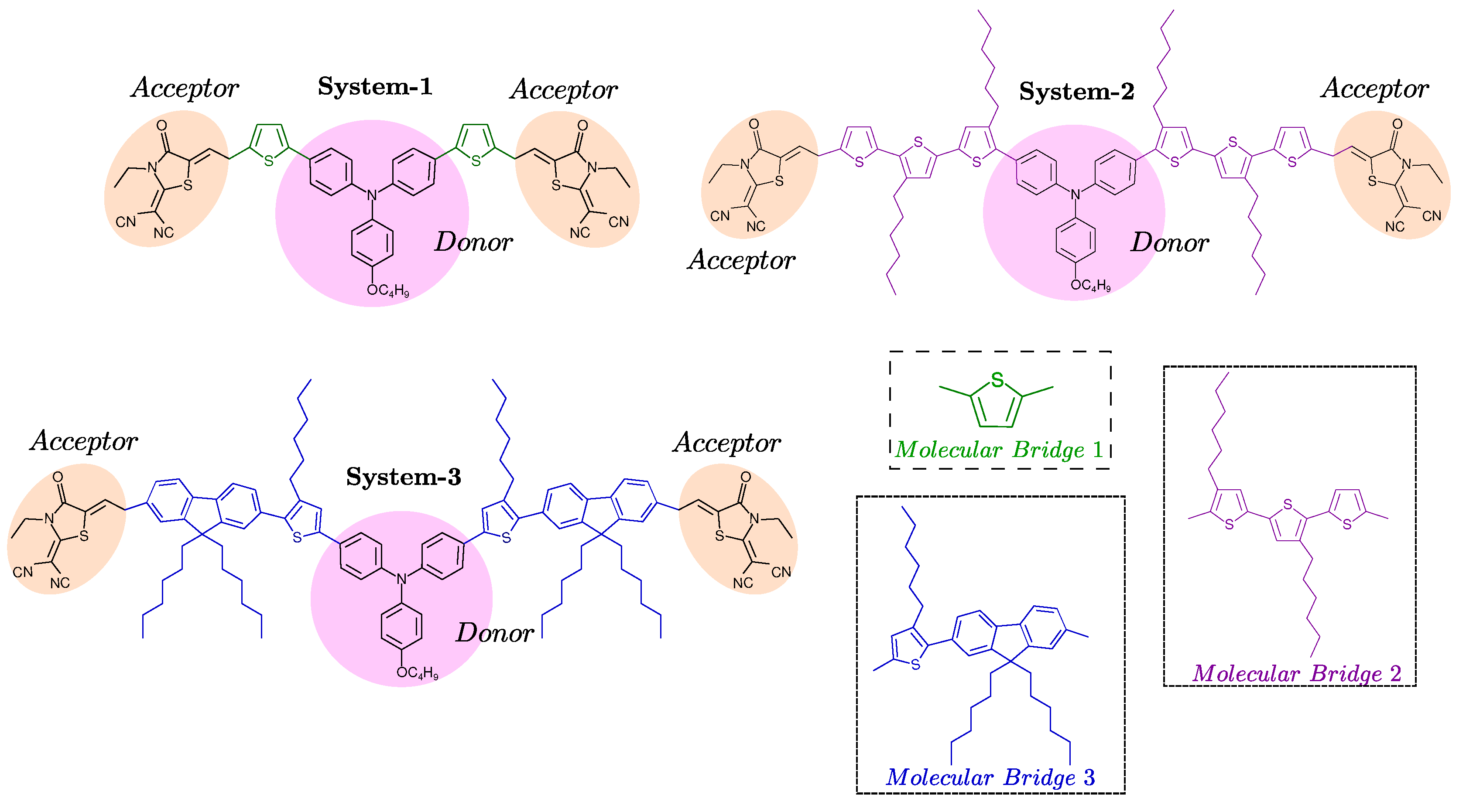
Figure 2.
Energy level diagram of the Kohn-Sham orbitals of the dyes System-1, System-2, System-3 calculated using density functional theory (DFT) for the EtOH solvent.
Figure 2.
Energy level diagram of the Kohn-Sham orbitals of the dyes System-1, System-2, System-3 calculated using density functional theory (DFT) for the EtOH solvent.
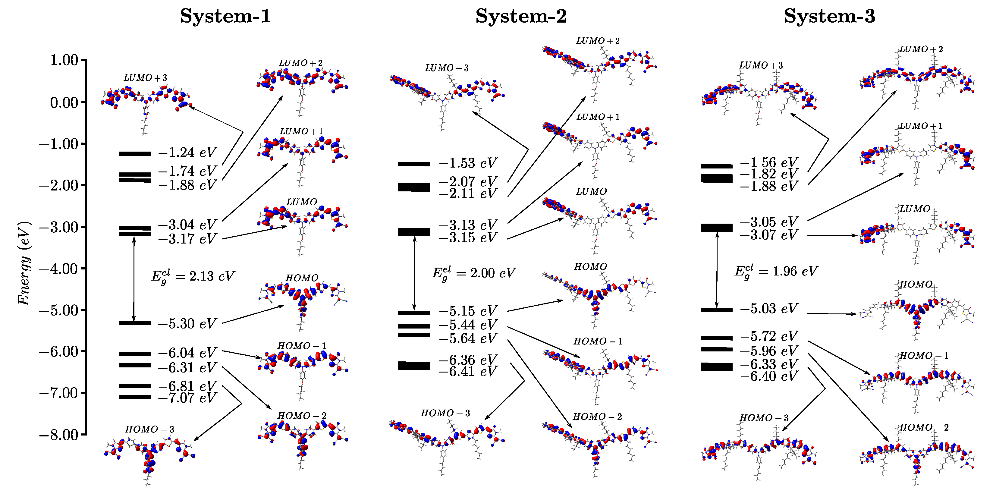
Figure 3.
UV-Vis absorption spectra of molecular systems based on triphenylamine and rhodanine obtained using TD-DFT with the CAM-B3LYB/6-31+G(d,p) basis set in the gaseous phase and ethanol solvent.
Figure 3.
UV-Vis absorption spectra of molecular systems based on triphenylamine and rhodanine obtained using TD-DFT with the CAM-B3LYB/6-31+G(d,p) basis set in the gaseous phase and ethanol solvent.
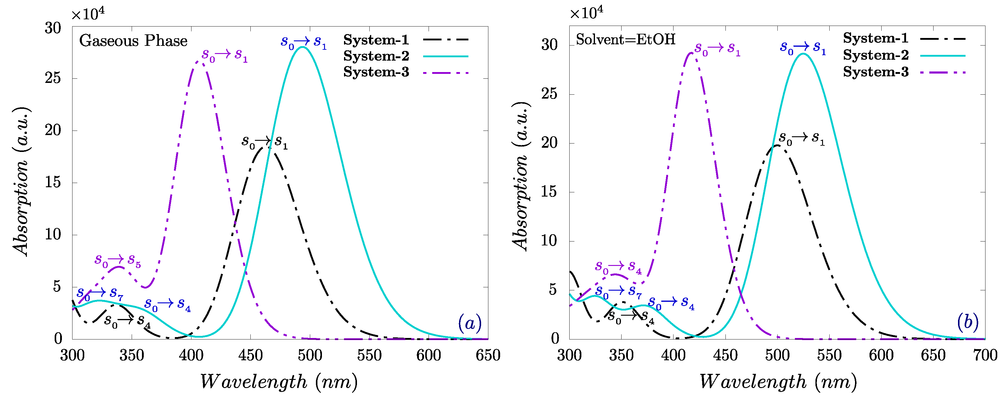
Figure 4.
Molecular electrostatic potential (MEP) maps of the molecular compounds System-1, System-2 and System-3.
Figure 4.
Molecular electrostatic potential (MEP) maps of the molecular compounds System-1, System-2 and System-3.
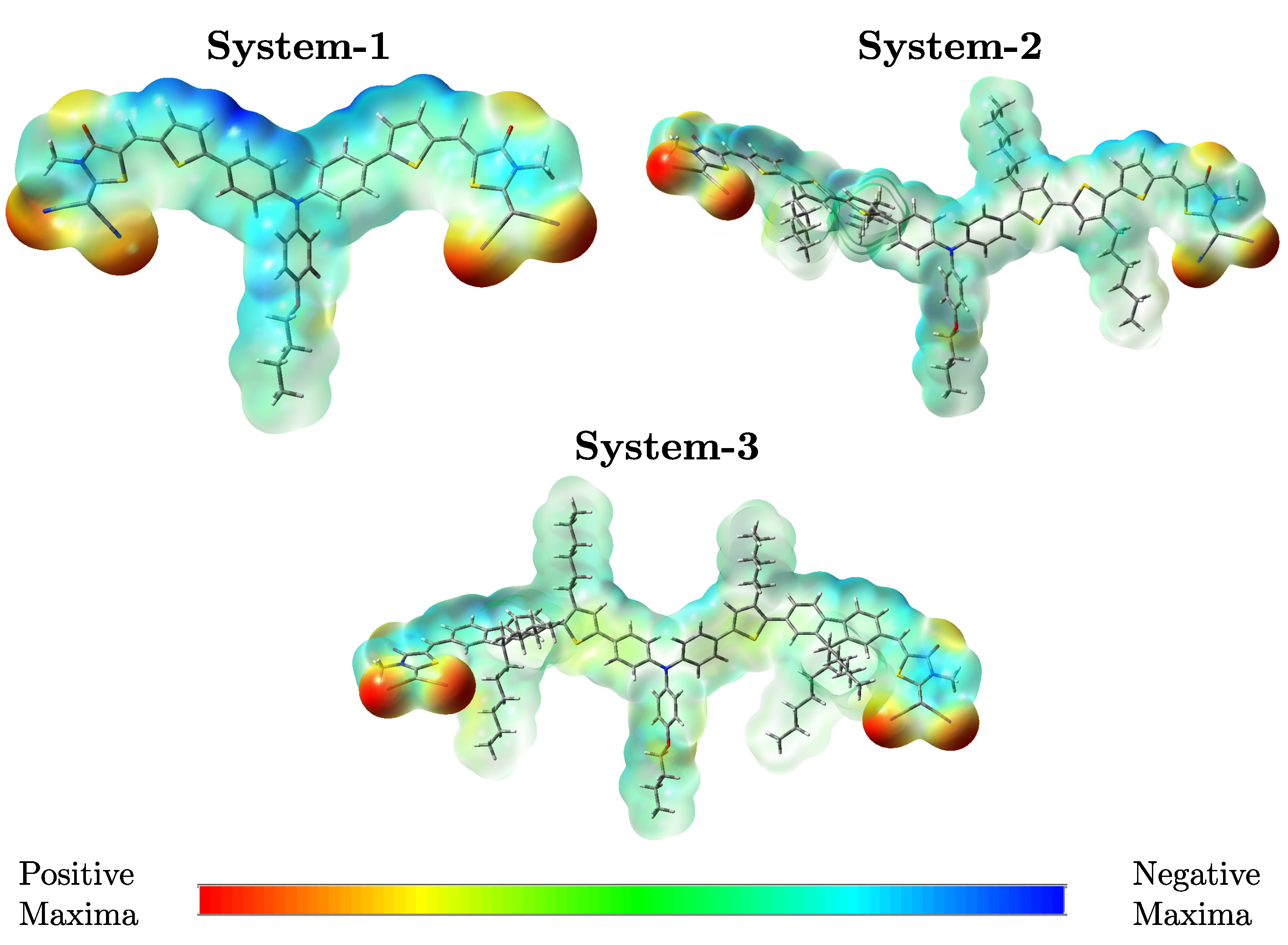
Figure 5.
Variation of in all developed compounds using acceptor PC61BM
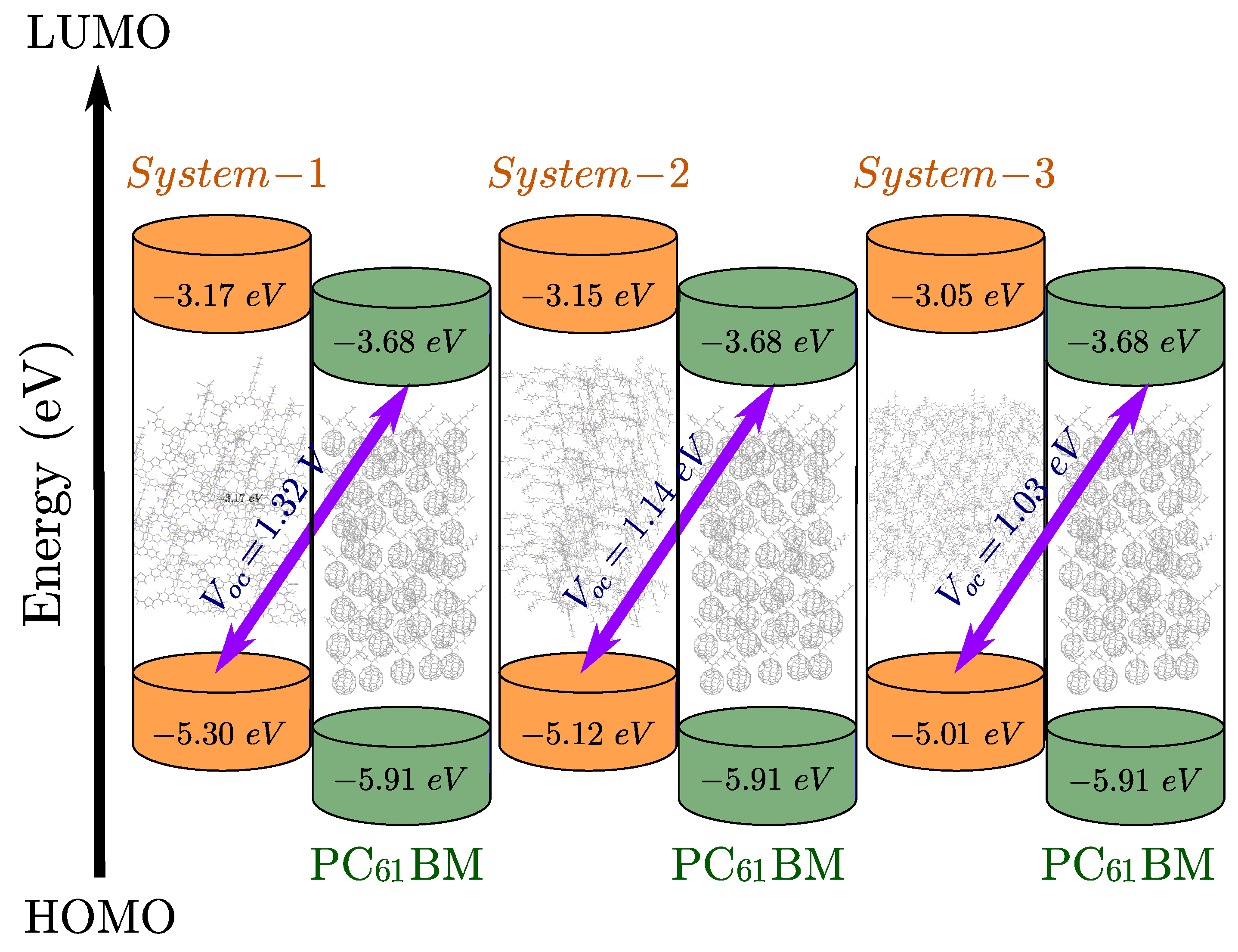

Table 1.
Calculated energies of the HOMO () and LUMO (), maximum absorption wavelength (), and band gap () for all studied molecular systems in the gas phase and ethanol.
Table 1.
Calculated energies of the HOMO () and LUMO (), maximum absorption wavelength (), and band gap () for all studied molecular systems in the gas phase and ethanol.
| System | (nm) | (eV) | (eV) | (eV) |
| Gas Phase | ||||
| System-1 | 462.40 | -5.58 | -3.28 | 2.30 |
| System-2 | 494.83 | -5.28 | -3.18 | 2.10 |
| System-3 | 407.60 | -5.07 | -3.10 | 1.97 |
| EtOH | ||||
| System-1 | 449.62 | -5.30 | -3.17 | 2.13 |
| System-2 | 525.55 | -5.12 | -3.15 | 1.97 |
| System-3 | 417.69 | -5.01 | -3.05 | 1.96 |
Table 2.
Wavelengths of the most important simulated transition states , oscillator strengths , excitation energy , and light harvesting efficiency .
Table 2.
Wavelengths of the most important simulated transition states , oscillator strengths , excitation energy , and light harvesting efficiency .
| System | States | (nm) | (eV) | LHE | |
| Gas Phase | |||||
| 462.40 | 2.681 | 2.549 | 0.9972 | ||
| System-1 | 335.04 | 3.701 | 0.292 | ||
| 494.83 | 2.506 | 3.368 | |||
| System-2 | 355.31 | 3.489 | 0.159 | 0.9995 | |
| 318.93 | 3.888 | 0.243 | |||
| 407.60 | 3.042 | 3.238 | |||
| System-3 | 337.73 | 3.671 | 0.569 | 0.9994 | |
| EtOH | |||||
| 499.62 | 2.482 | 2.725 | 0.9981 | ||
| System-1 | 347.78 | 3.565 | 0.320 | ||
| 525.55 | 2.359 | 3.509 | |||
| System-2 | 369.69 | 3.354 | 0.233 | 0.9996 | |
| 326.14 | 3.802 | 0.397 | |||
| 417.69 | 2.968 | 3.447 | |||
| System-3 | 347.79 | 3.565 | 0.404 | 0.9996 |
Table 3.
Estimated values for the electron reorganization energy (), hole reorganization energy (), ionization potential (IP), electron affinity (EA), and dipole moment () of all investigated molecular dyes in ethanol (EtOH) and gas phase.
Table 3.
Estimated values for the electron reorganization energy (), hole reorganization energy (), ionization potential (IP), electron affinity (EA), and dipole moment () of all investigated molecular dyes in ethanol (EtOH) and gas phase.
| Systems | (eV) | (eV) | (eV) | (eV) | (D) |
| EtOH | |||||
| System-1 | 0.316 | 0.201 | 5.379 | 3.284 | 13.504 |
| System-2 | 0.142 | 0.233 | 5.302 | 3.325 | 16.762 |
| System-3 | 0.317 | 0.198 | 5.198 | 3.374 | 18.258 |
| Gas Phase | |||||
| System-1 | 0.261 | 0.220 | 6.768 | 2.084 | 9.063 |
| System-2 | 0.164 | 0.285 | 6.502 | 2.121 | 11.672 |
| System-3 | 0.219 | 0.209 | 6.309 | 1.937 | 13.042 |
Table 4.
Parameter values of the studied molecular compounds include the exciton driving force , open circuit voltage (), short-circuit current density (), fill factor (), and power conversion efficiency (PCE) in the solvent ethanol (EtOH).
Table 4.
Parameter values of the studied molecular compounds include the exciton driving force , open circuit voltage (), short-circuit current density (), fill factor (), and power conversion efficiency (PCE) in the solvent ethanol (EtOH).
| System | (eV) | (V) | (mA/cm2) | (%) | |
| System-1 | 0.51 | 1.32 | 9.52 | 0.810 | 10.18 |
| System-2 | 0.53 | 1.14 | 12.21 | 0.786 | 10.95 |
| System-3 | 0.63 | 1.03 | 11.85 | 0.774 | 9.45 |
Disclaimer/Publisher’s Note: The statements, opinions and data contained in all publications are solely those of the individual author(s) and contributor(s) and not of MDPI and/or the editor(s). MDPI and/or the editor(s) disclaim responsibility for any injury to people or property resulting from any ideas, methods, instructions or products referred to in the content. |
© 2025 by the authors. Licensee MDPI, Basel, Switzerland. This article is an open access article distributed under the terms and conditions of the Creative Commons Attribution (CC BY) license (http://creativecommons.org/licenses/by/4.0/).
Copyright: This open access article is published under a Creative Commons CC BY 4.0 license, which permit the free download, distribution, and reuse, provided that the author and preprint are cited in any reuse.


