Submitted:
08 August 2025
Posted:
13 August 2025
You are already at the latest version
Abstract
This paper talk about to develop the methodology of the GD&T (Geometric Dimensioning and Tolerancing) philosophy in conjunction with rapid prototyping and Reverse Engi-neering technology, to achieve the improvement of product parts. Collaterally and in a complementary way, this article, show the necessary to develop measurement techniques by variables, focusing on measurement by coordinates, for the survey of pieces by Reverse Engineering and quality control in production, as well as the development of functional gauges as a method of control by attributes, using GD&T and rapid prototyping tools. All this applied to a piece to be designed. The research methodology used is a quantitative strategy, based on an experimental study. This decision was based on the need to identify and analyze the behavior of empirical data by taking measurements with a coordinate measuring machine to apply reverse engineer-ing to the part to be manufactured. To implement the proposed method, measurements were taken on a part similar an airbag control support base made of AA 7075 aluminum. Later, the part was drawn in a CAD system, applying GD&T to both dimensional and geometric dimensions of the part, thus obtaining the expected result.
Keywords:
GD&T
; CMM
; reverse engineering
; 3D printing
; geometric tolerances
; ASME Y14.5
; design
; metrology
1. Introduction
GD&T (Geometric Dimensioning and Tolerancing) is a dimensioning methodology, a universal symbolic language, used to differentiate a good part from a bad one, but always from a functional point of view, so that the rejected part is a non-functional part, that is, one that does not fit with its geometric counterpart. [1]
Reverse engineering is the process of disassembling, analyzing, studying, evaluating, and understanding a product to understand how it works, how it was built, which components are contained. It is used, for example, to create replicas, improve existing products, or simply to understand the operation of a machine or system.
It can be said that GD&T and reverse engineering are two linked but different concepts. Basically, reverse engineering is a process of analyzing and studying an object to understand its design and function, while GD&T is a methodology that allows defining and controlling the geometric tolerances of manufactured parts. GD&T is applicable to reverse engineering because it ensures that parts manufactured from an original have the correct geometric dimensions and tolerances, which is critical to their operation, coupling, and obtaining an adequate fit.
There are two types of engineering: direct engineering, in which the part is manufactured from a drawing, and reverse engineering, which is the opposite process.
There is no single definition of reverse engineering. Some of them are:
“Reverse engineering represents the process of analyzing a system with two goals in mind: 1) to identify the system's components and their relationships, and 2) to create representations of the system in another form or at a higher level of abstraction.” [2]
“Reverse engineering is the process of designing a substitute that acceptably replaces a product or part. In this case, reverse engineering is a particular case of redesign based on various aspects of the original product and on the analysis of a sample. It is applied when the design process or documentation is unavailable.” [2]
“Reverse engineering is an analytical-synthetic process that seeks to determine the characteristics and/or functions of a system, machine, or product, or a part of a component or subsystem. The purpose of reverse engineering is to establish a generic model of an object, product, or reference system. [2]
It can be said that reverse engineering is the process followed to obtain a duplicate from a reference object. [2]
The information obtained, transformed into a model, is called a duplicate (reproduced object B) reference object A. In summary, reverse engineering has the following primitive elements [2]:
1) the reference object (A), also called the initial object
2) the reproduced object (B), also known as the final object
3) the set of specific relation between the mentioned objects
The stages of reverse engineering [2] are:
Step 1: Preliminary knowledge of the reference object (A)
Step 2: Design of a research plan and its corresponding program of activities
Step 3: Application of the plan to the reference object (A)
Step 4: Synthesize the information obtained from applying the plan, generate model B, and demonstrate that B ~ A (equivalence or similarity between A and B).
Step 5: Characterize model B
Step 6: Use B for various purposes
It should be noted that 3D scanning has become a very valuable tool in the application of reverse engineering, and that the acquisition of three-dimensional points of a part allows for the development of models and product analysis. [4]
Figure 1 explains the 3D printing process. [5]
Regarding 3D printing, it is important to consider that there are modeling deviations, so it is crucial to apply GD&T to the part drawing to achieve proper printing. [5]
This is achieved in the pre-dimensioning stage of the CAD model, considering several aspects related to coupling, the deformation generated by the 3D printing process, and ensuring the correct coupling of the part with its geometric counterpart through the application of GD&T. [5]
It is very important to use a project methodology applied to product development, since without it, information would be incorrectly detailed, generating potential complications in the production process, and it would not be possible to provide uniformity in specifications. [6]
This is why GD&T is used, since GD&T is a set of symbols, rules, definitions, and conventions; that is, it is a symbolic language used to describe the size, form, orientation, and location of parts. [6]
Geometric tolerances are expressed by means of the feature control frame. See Figure 2.
Basically the control frame shows the tolerance symbol, the tolerance with its features in the corresponding cases, and the datums or references that represent not only the way of fixing the piece, but also the order of precedence when fixing the piece and restricting its movements, the six degrees of freedom, these being the three translations and rotations on the x,y,z axes. [7]
The five categories of geometric tolerances and their symbols are shown in Figure 3.
GD&T is applied to product development using, as a measurement element, a coordinate measuring machine of any type, allowing for a comparison between the previously designed mathematical model and the actual part, obtained through the collection of points. [6]
It is common to apply the GD&T methodology to product development, such as in the case of a bus body manufacturer, applying it to a windshield, using as a measuring element to carry out the metrological survey a portable three-dimensional measuring arm with a scanner and built-in spherical probe. [6]
The use of a measuring arm and its software allows for the comparison of the previously designed mathematical model and the actual part, obtained by collecting the points, with the scanner attached to the equipment. [ 6]
It is important to consider measurement uncertainty when measuring parts and link it to GD&T. There are many sources of uncertainty, caused by the complex system of mechanical components found in coordinate measuring machines and environmental variations. Therefore, it is necessary to develop a measurement uncertainty assessment method. [8]
Multi-sensor systems can also be used for inspection with coordinate measuring machines, combining, for example, laser and contact scanning, among others, to increase speed and reduce measurement uncertainty on complex surfaces. [9]
It is important to consider several aspects when planning measurements with coordinate measuring machines. For example, inspection standards, GD&T, measurement technology, the manufacturing process along with the part specifications, and very important, the personnel in relation to their training and technical competence. [9]
The main objective of this work is to develop a documented method based on the application of GD&T to obtain product parts through reverse engineering, thereby linking the mechanical design, manufacturing, and inspection processes.
The objective was obtained by developing a documented method and improving the resulting part through reverse engineering and another important aspect was the production of a functional gauge.
2. Materials and Methods
The research methodology adopted is experimental, that is, based on a quantitative strategy. This decision is based on the need to identify and analyze the behavior of empirical data by taking measurements with a coordinate measuring machine to apply reverse engineering based on the dimensional measurements of the product part to be manufactured.
The motivation for selecting the research topic was to develop and establish a method that links reverse engineering, metrology, 3D printing, GD&T and design and manufacturing engineering to obtain engineering documentation that connects design, manufacturing and metrology, for both forward and reverse engineering, using a common language. The diagram in Figure 4 illustrates the above.
To implement the proposed method, the dimensional measurements was performed on a product part, in this case a similar airbag control support base made of aluminum and zinc alloy (AA 7075), shown in the photo in Figure 5. The part was then drawn in a CAD (Computer-Aided Design) system, applying GD&T to both the dimensional and geometric dimensions of the part.
The steps of the method are:
1) Analysis of the part to be manufactured
2) Definition of the measurand, method, and equipment
3) Material study (tests)
4) Dimensional measurements
5) Analysis of measurements and tests
6) 3D printing of the prototype
7) Functional calibration (if required)
8) Analysis of results
9) Final design and generation of engineering documentation
10) Manufacturing the actual prototype
11) Analysis of results
12) Approval of the reverse engineering design
From the steps mentioned above, a flowchart was created and then the reverse engineering service procedure was written. See Figure 6.
The materials, equipment, infrastructure, and resources were provided by the National Technological University, General Pacheco Regional Faculty (UTN FRGP) and the activities were developed in LABTEC. This is the Technological Laboratory of the National Technological University, General Pacheco Regional Faculty.
The materials, equipment, infrastructure, and resources are detailed below:
-LABTEC Staff
-Coordinate measuring machine Model :BH-V500/700 Bright-M 500/700 with contact probe ,Resolution: 0.001 mm Measuring volume: X-axis: 500 mm,Y-axis: 700 mm,Z-axis: 400 mm Weight: 700 kg and Software: GEOPAK V3.0 measurement
- 3D Printer :Trideo Print Box Max 30x30 (LABTEC-UTN FRGP)
- LABTEC Coordinate Measurement Laboratory under IRAM ISO/IEC 17025:2017 standard and LAB36-UKAS guidelines.
- LABTEC Offices: Two (two) General Management and Technical Metrology Management Offices.
- LABTEC Quality Management System using the "Documentation Control" procedure (LTP01) and the "Guide for Document Preparation" annex (LTP01-R02) to implement procedures, instructions, certificates, and other Quality Management System procedures deemed necessary.
3. Results
3.1. Information analysis
The part and information about it were obtained. In this case, the drawing. See Figure 7.
The drawing in Figure 6 shows the following missing information: datum (two are missing; only datum A appears), basic dimensions, dimensional origin, true position (in three holes), general dimensional tolerance is missing from the label, diameters of 8 mm without dimensional tolerance and radii R7 and R14 without dimensional tolerance.
The Figure 6 indicates that the part has a single datum (Datum A), so the restriction of the six degrees of freedom, i.e., the three translations and three rotations, is not guaranteed. This means that if the part is not properly clamped. There is great difficulty in materializing the theoretical centers of the holes, thus not ensuring the coupling between the part and its counterpart. This is because there is no true position or concentricity/coaxiality tolerances either, since they are not included in the feature control frame.
In Figure 6, the only feature control frame shown are the parallelism and perpendicularity charts for the 33 mm hole. The latter symbol could be replaced by a position symbol with a cylindrical tolerance zone, which would include the possibility of considering the macro geometric error of perpendicularity.
Measurements, tests and document generation
The Figure 8 shows the reverse engineering process and its main activities.
After analyzing the part information, measurements were taken with coordinate measuring machine (CMM) to facilitate reverse engineering, and the dimensional measurements were used to design the workpiece to be manufactured. An example of the measured values is shown in Figure 9.
At the same time as the dimensional measurements, tests were performed to characterize the material. The tests performed included tensile strength, Brinell hardness, and spark optical emission spectroscopy. The tests were carried out at INTI.
Spark optical emission spectroscopy (OES-spark): the determination was performed with a spectrometer following the guidelines of ASTM E1251-17a Standard Test Method for Analysis of Aluminum Alloys by Spark Atomic Emission Spectrometry. The results obtained are presented in the table of the Figure 10.
The test results were analyzed, and it was determined that the material is an AA type aluminum alloy.
The Figure 11. shows the tensile strength and hardness tests performed. The samples used and the tensile strength and Brinell hardness test equipment can be seen.
It is important to indicate that the reverse engineering process was carried out following the methodology developed in the materials and methods section of this document. The following procedures were developed:
LT-I37 Dimensional Measurement of workpiece with a Coordinate Measuring Machine
LT-I37-R01 Dimensional Measurement of workpiece with a Coordinate Measuring Machine and Pattern
LT-I38 Coordinate Measuring Machine User Manual
LT-I38-R01 CMM Software User Manual
LT-I39 "LABTEC Pressure Recipient Control Management"
LT-I38-R02 Simplified CMM Software User Manual
LT-I40 Reverse Engineering Service
To document the entire methodology developed for performing reverse engineering activities, the instruction "Reverse Engineering Service" (LT-I40) was prepared.
CAD Modeling and GD&T
Once the measurement values were obtained, the part was drawn in a CAD system, the functional gauge was designed, and 3D prints of the prototypes were made. The part was drawn in a CAD system for reproduction on a 3D printer and a machine tool. It is possible to see this in Figure 12.
The Figure 13 shows the drawing of the part to be reproduced on a 3D printer as a prototype, with the purpose of evaluating its functionality with a functional gauge developed with the technology mentioned above.
For this case, a three-plane “clamping” system was adopted, allowing the datum simulators to be implemented in the metrology laboratory by means of two fixing squares and a reference surface, and on the machine tool, using the machine tool table and two fixing squares.
The Figure 8 shows the dimensions whose tolerances have been increased because the tolerances used for sizing 3D printed parts are wider than those applied to aluminum parts. The reasons for this criterion are due to various factors, especially those related to the manufacturing process and the material used.
It is important to note that the part to be manufactured in AA 7075 aluminum is generally manufactured using subtractive manufacturing, so the assigned tolerances are smaller than 3D printer technology, especially if manufactured with computer numerical control machines. In contrast, in 3D printing, plastic materials are used. Polymers are subject to contraction.
Contraction is due to various factors, such as thermal expansion, polymer solidification, internal stresses, and the thermodynamics of the manufacturing process. [10]
Thus, the dimensional contraction happens when the plastic material used for printing cools and depends on the type of material used. This is the reason why tolerance values must be increased. Everything discussed in the previous paragraphs is also applicable to the manufacture of functional gauge by 3D printing.
The Figure 14 shows the drawing of the part to be manufactured on a machine tool, and in this case, the tolerances are smaller than those established in Figure 13.
The functional caliber prototype was manufactured on a 3D printer in the same way as the part. The reasons for increasing the tolerances of the functional gauge are the same as those explained in this paper and are due to the dimensional contraction of the impression material. See Figure 15.
Figure 16 shows the drawing of the functional gauge made for a piece of AA7075 aluminum alloy.
Once the prototypes of the part and the functional gauge were printed, they were coupled to verify their functionality. The result was correct. Therefore, the part was approved by functional control, as can be seen in Figure 17.
In Figure 18, the original part subjected to reverse engineering enter the functional gauge.
After checking the part and the functional caliber printed on a 3D printer, the part and its functional gauge were manufactured in AA7075 aluminum alloy as shown in Figure 19.
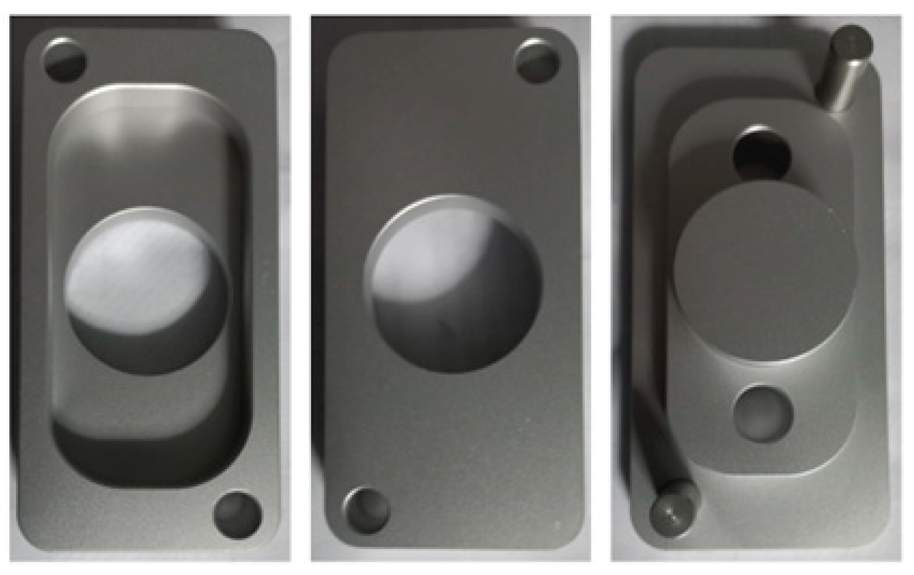
Once the functional gauge and the part, both made of AA7075 aluminum alloy, were available, they were coupled, achieving a satisfactory result.
The reverse engineering is not a copy of a part or product, but rather an improved version, where, after analysis, defects are discovered and look for improvements. To get this, it was decided to perform a blasting treatment on the part and its functional gauge. It is possible said that the blasting treatment and the functional gauge, both are the improvement. The result is possible to see in the Figure 20.
4. Discussion
Regarding the scope of the study, the measurements were made with a coordinate measuring machine with a contact probe. However, other types of non-contact measuring machines can be used, such as tomographs, scanners, and photogrammetry measurements. Another possibility is to conduct experiments with measuring arms. These could be other lines of development, including bilateral comparisons with some of the equipment mentioned above.
The functional gauge constitutes an innovation compared to the original product and a rapid control tool that can be applied in the serial manufacturing process.
Testing revealed the type of material and its characteristics. In this case study, an aluminum-zinc alloy (AA7075).
The method for evaluating the uncertainty of measurements and the determination of their sources were both developed and used in this research but should be explained in detail in another specific paper.
Written procedures allowed for the establishment of standard methods for the different activities that are part of measurements and reverse engineering.
The application of the proposed methodology made it possible to manufacture parts without generating scrap. This was because the drawing was well executed, applying the GD&T rules and tools.
Reverse engineering, combined with GD&T, is a useful tool for understanding and reproducing products, especially when information is needed from an existing design or product without access to original drawings or specifications. GD&T, on the other hand, is a system that defines and communicates the geometric tolerances of a design, allowing designers, production, and quality control personnel to control process variations during manufacturing.
The two complement each other when analyzing and replicating components. Reverse engineering provides information about a product's design and manufacturing, while GD&T ensures the correct interpretation of geometric tolerances to replicate the part as faithfully as possible.
This research work allowed us to create a working group with members from different disciplines and organizations. This created a space for mutual collaboration.
5. Conclusions
The objective was got because the results obtained were as expected, the measurement method selected was appropriate and the measuring equipment too. The same applies to the tests chosen to understand and characterize the material.
The correct design of the workpiece and the functional gauge allowed for scrap-free manufacturing. This result was achieved through a combination of GD&T tools and reverse engineering.
The application of reverse engineering not only allowed for the improvement of the original part, but also for the creation of a functional gauge for its control.
Having a written reverse engineering service procedure and other related procedures allows for standardized repetition of reverse engineering processes in the same way.
Based on experience, it can be stated that reverse engineering combined with GD&T allows for obtaining information about an existing product, creating detailed drawings and specifications, manufacturing parts with precision and quality to reduce scrap, and enabling the creation of similar or improved products.
Acknowledgements
We would like to thank the following people for their cooperation and important contribution: Dr. Eng. María Belén Parodi (INTI). Eng. Víctor Pereyra (CENTEC). Eng. Hernán Lorusso (INTI). Eng. Oscar Medvescig (LABTEC-UTN FRGP). Lic. Hernán Varela (LABTEC-UTN FRGP). Tec. María Emilia Boedo (INTI). Tec Univ. Ayelén Borges (LABTEC-UTNFRGP)
Abbreviations
The following abbreviations are used in this manuscript:
| GD&T | Geometric Dimensioning and Tolerancing |
| CAD | Computer-Aided Design |
| AM | Additive manufacturing |
| RE | Reverse engineering |
| CMM | Coordinate Measuring Machine |
| CNC | Computer Numerical Control |
| LABTEC | Technological Laboratory of the National Technological University, General Pacheco Regional Faculty |
| UTN FRGP | National Technological University, General Pacheco Regional Faculty |
| INTI | National Institute of Industrial Technology |
| UKAS | United Kingdom Accreditation Service |
References
- Sancho Rodenas.J “Tolerancias Geométricas”, Barcelona: Tecnomesura, Print Mania S.L., 2007.
- E.J.Lopez, A.L.Bracamontes, L.A.G Velazquez , V.M.Molina “La ingeniería inversa como metodología para potenciar la enseñanza de la metrología”, Simposio de Metrología 2010 , Santiago de Quétaro.
- Iglesias.M “Tolerancias Geométricas GD&T Geometric Dimensioning and Tolerancing : Basado en ASME Y14.5-2018 : Incluye ajustes y tolerancias y temas de metrología dimensional” , 1a edUTecNe, 2021. Tomo 1.
- L.E.Isaza, I.Moreno,E.Salazar, “Aplicación de ingeniería inversa para manufactura de figuras orgánicas complejas :caso de aplicación”, First International Conference on Advanced Mechatronics, Design, and Manufacturing Technology - AMDM ,2012.
- B.Rupal , A. Qureshi “Geometric Deviation Modeling and Tolerancing in Additive manufacturing: A GD&T Perspective”, Conferencce of NSERC Network for Holistic Innovation in Additive Manufacturing (HI-AM),Waterloo,Canada,2018 OK 6-1-25.
- T.Zilio,C.Viero y M.Walber , “GD&T – Aspectos relacionados ao el desenvolvimento de productos”,Revista CIATEC-UF,Vol 6, 2014.
- Dagaz Silva.M ,Souza de Paulo.D “A norma ASME Y14.43 de 2011 relativa a dispositivos usados em processos de fabricação”, São Bernardo do Campo, VIII Simpósio de Iniciação Científica, Didática e de Ações Sociais da FEI,2018.
- Satto, T.Takatsuji, Y.Miura ,S. Nakanishi , “GD&T task specific measurement uncertainty evaluation for manufacturing floor ”, Measurement: Sensors 18 (2021) 100141,ElSEVIER,2021.
- M Pellitero“ Modelo de Conocimiento para la Planificación Automática de la Inspección en Máquinas de Medir por Coordenadas”, Tesis Doctoral, Universidad de León, 2015.
- E.Valverde Lorenzo , “Análisis de la influencia de la temperatura de la cámara en piezas fabricadas por impresión 3D por la tecnología FFF”, Universidad de Valladolid,Escuelas de Ingenierías Industriales,2018.
Figure 1.
Generic stages of additive manufacturing (AM).
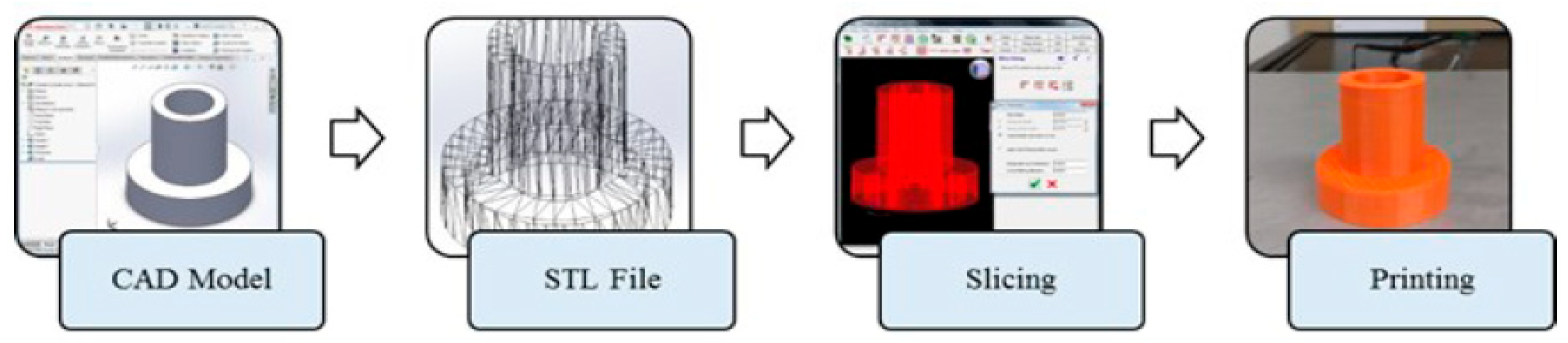
Figure 2.
Feature control frame.
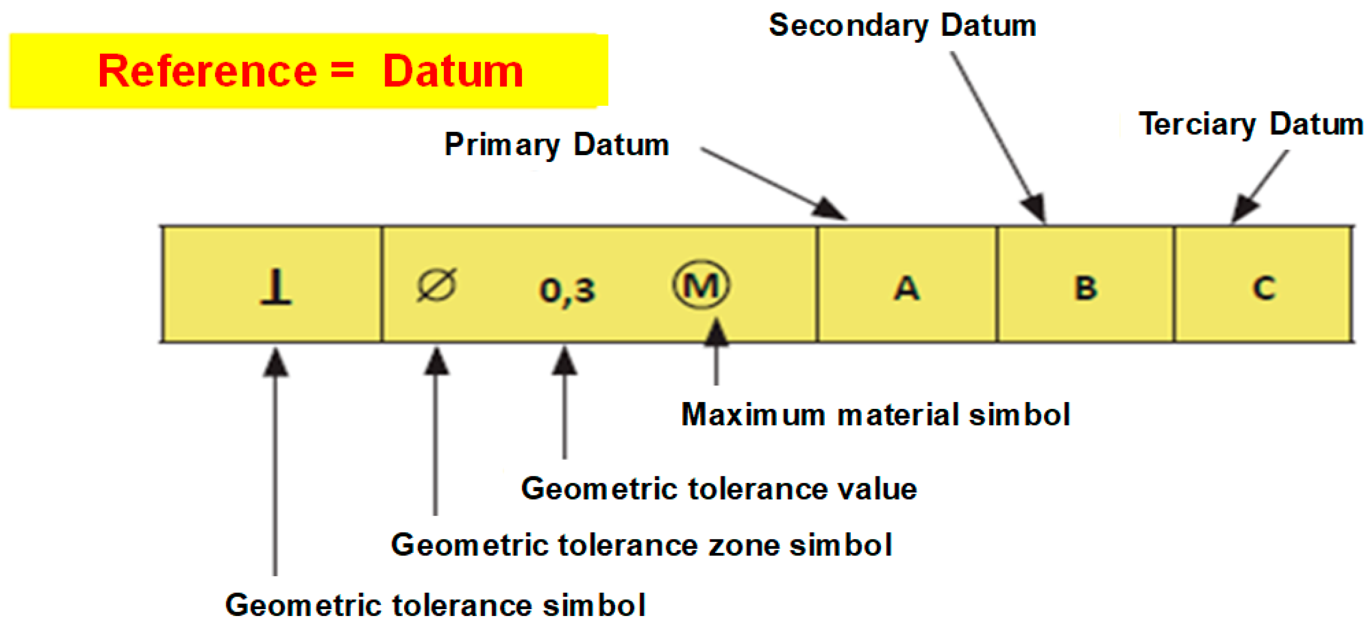
Figure 3.
Geometric tolerance symbols.
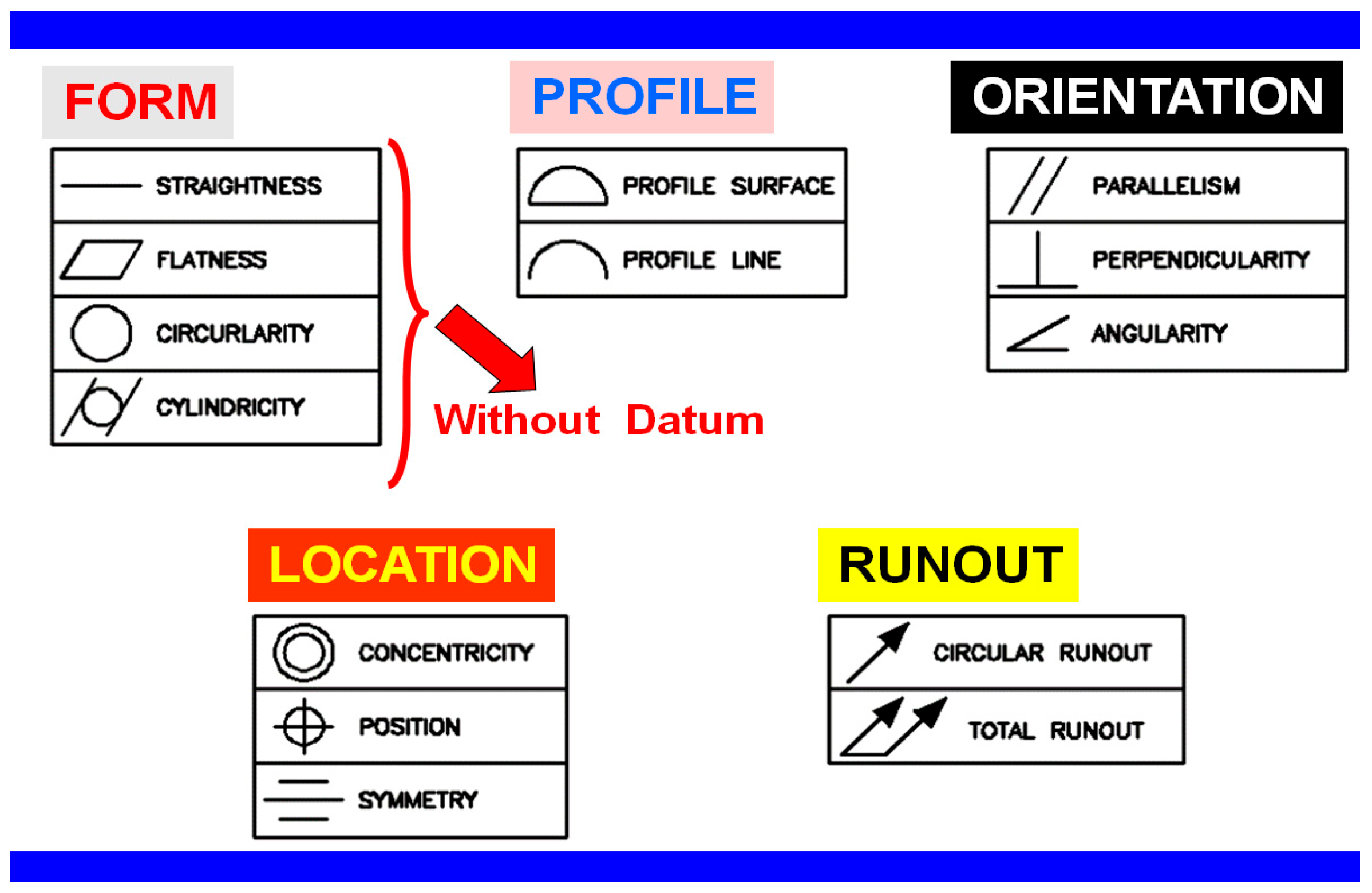
Figure 4.
Methodology to be developed.
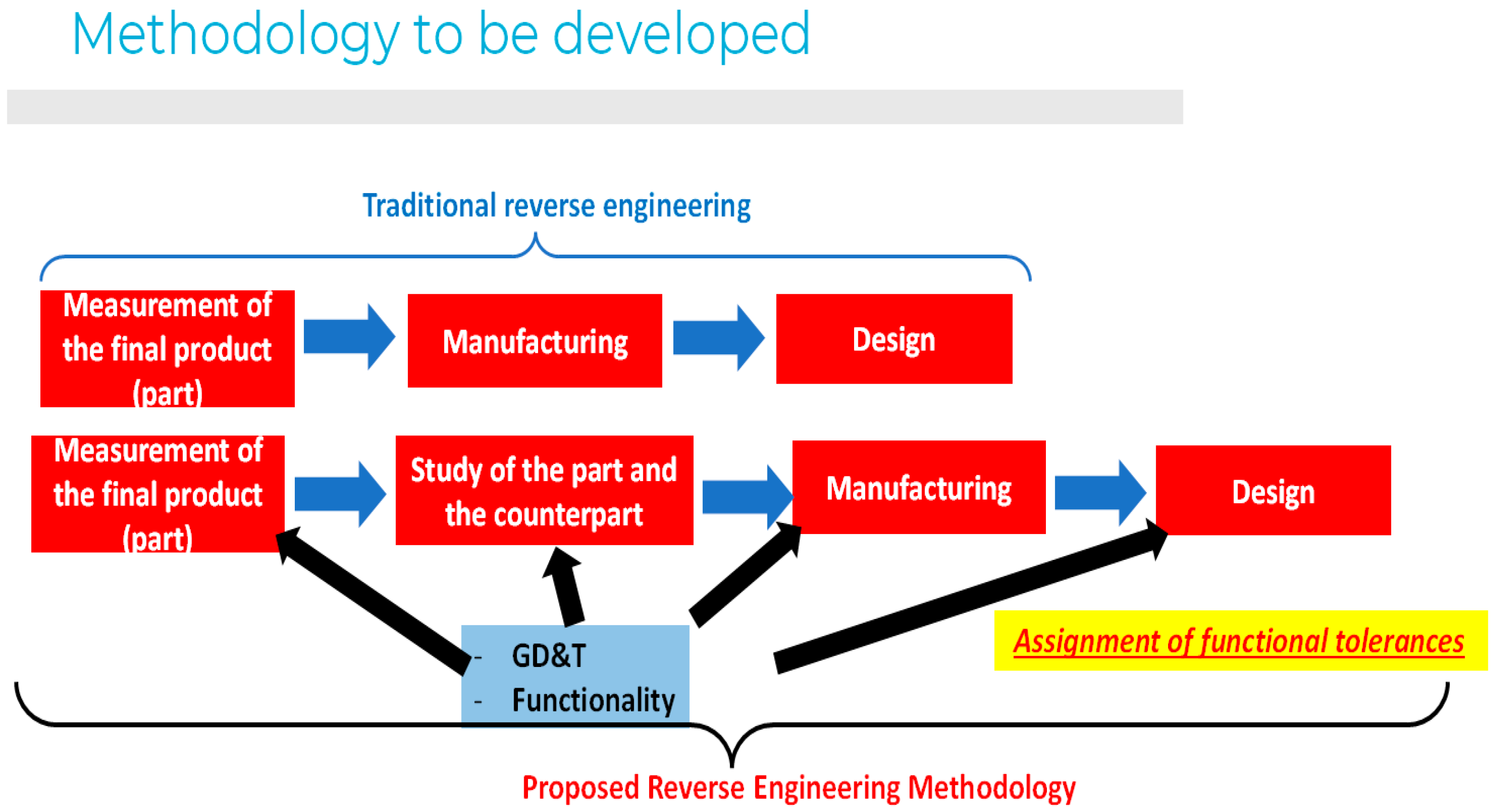
Figure 5.
Reverse engineering part -similar to airbag control support base.
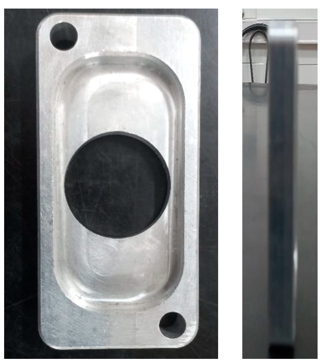
Figure 6.
Flowchart and reverse engineering service procedure.
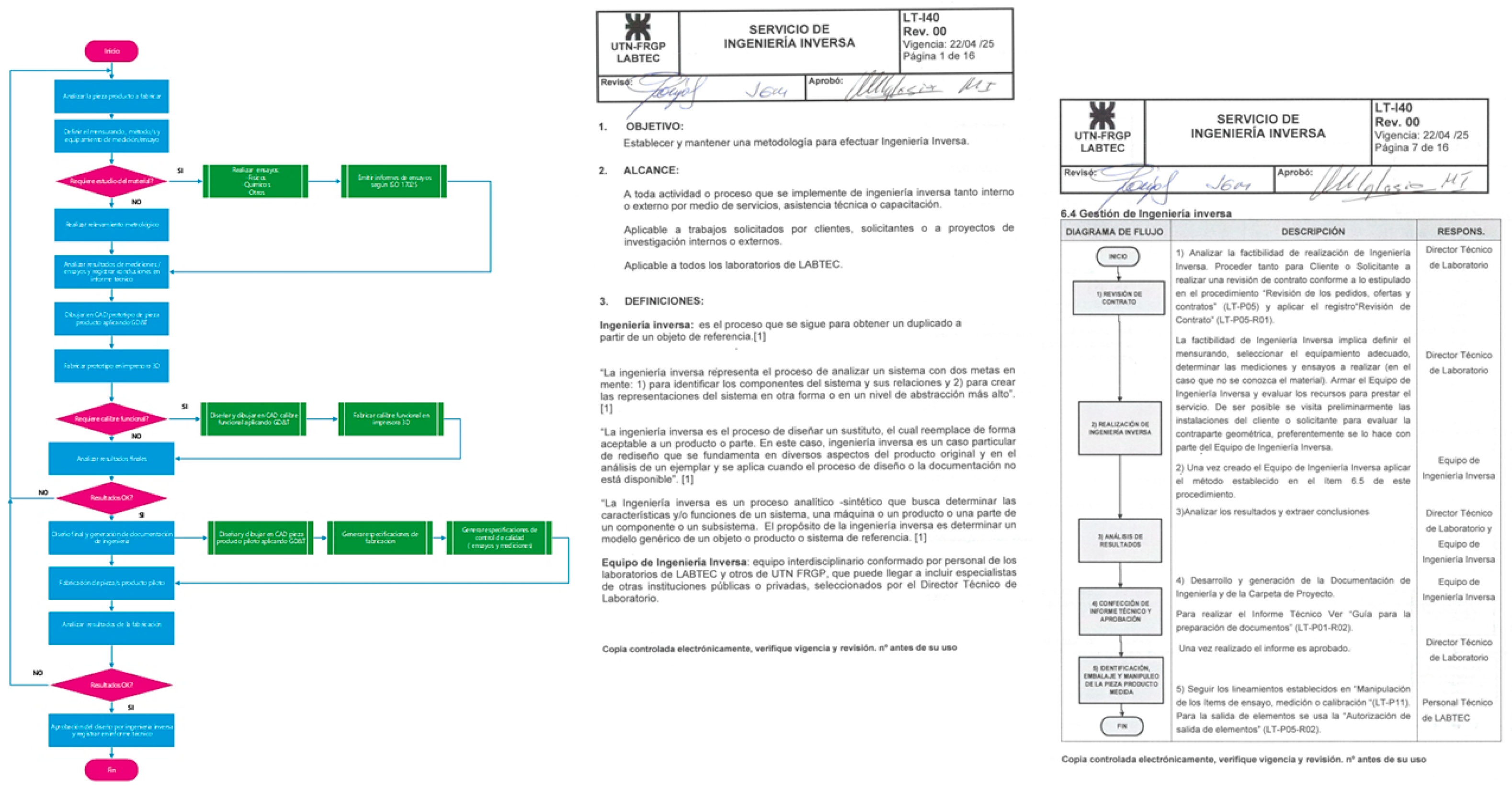
Figure 7.
Drawing of the original piece with insufficient information.
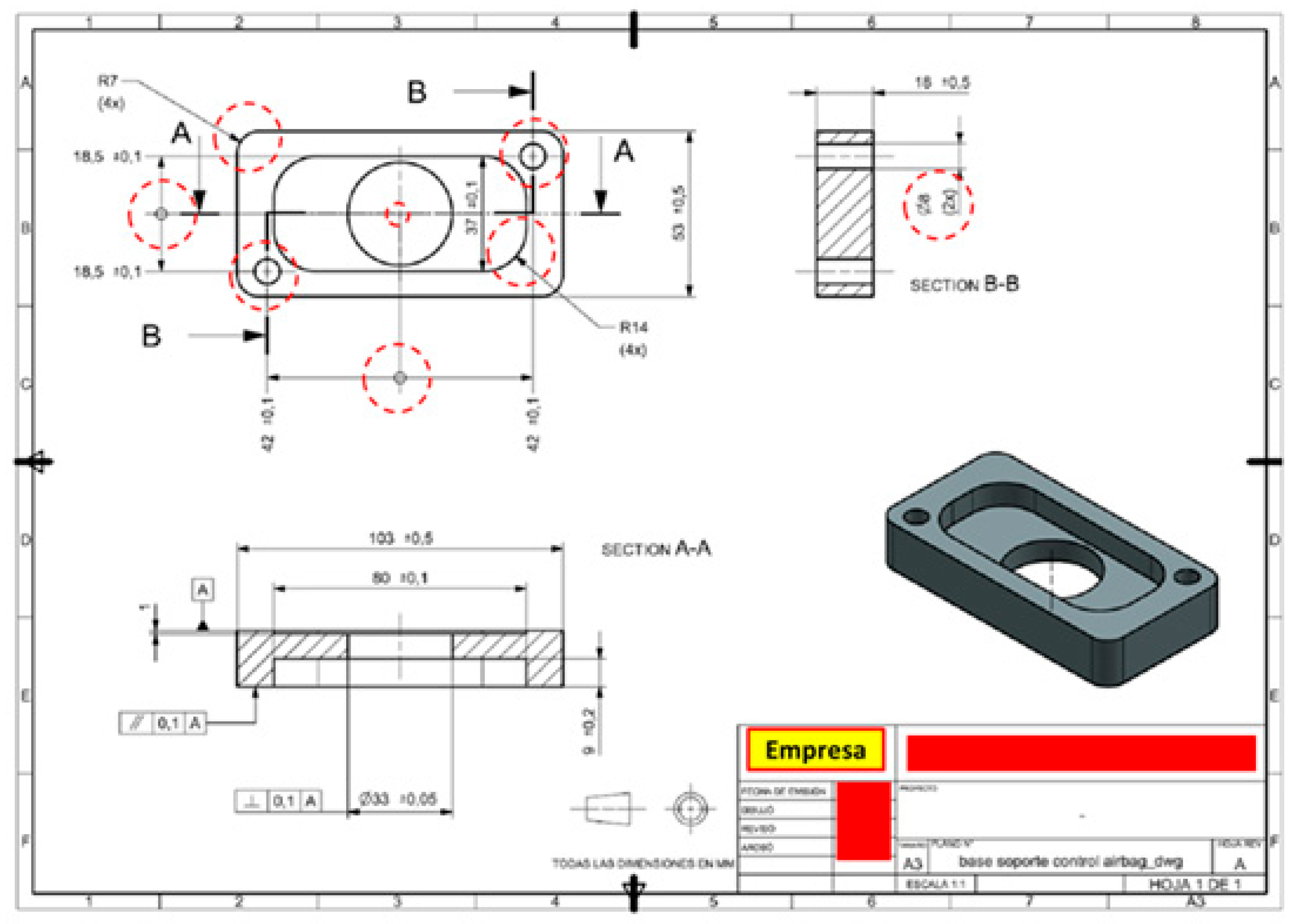
Figure 8.
Reverse engineering process.
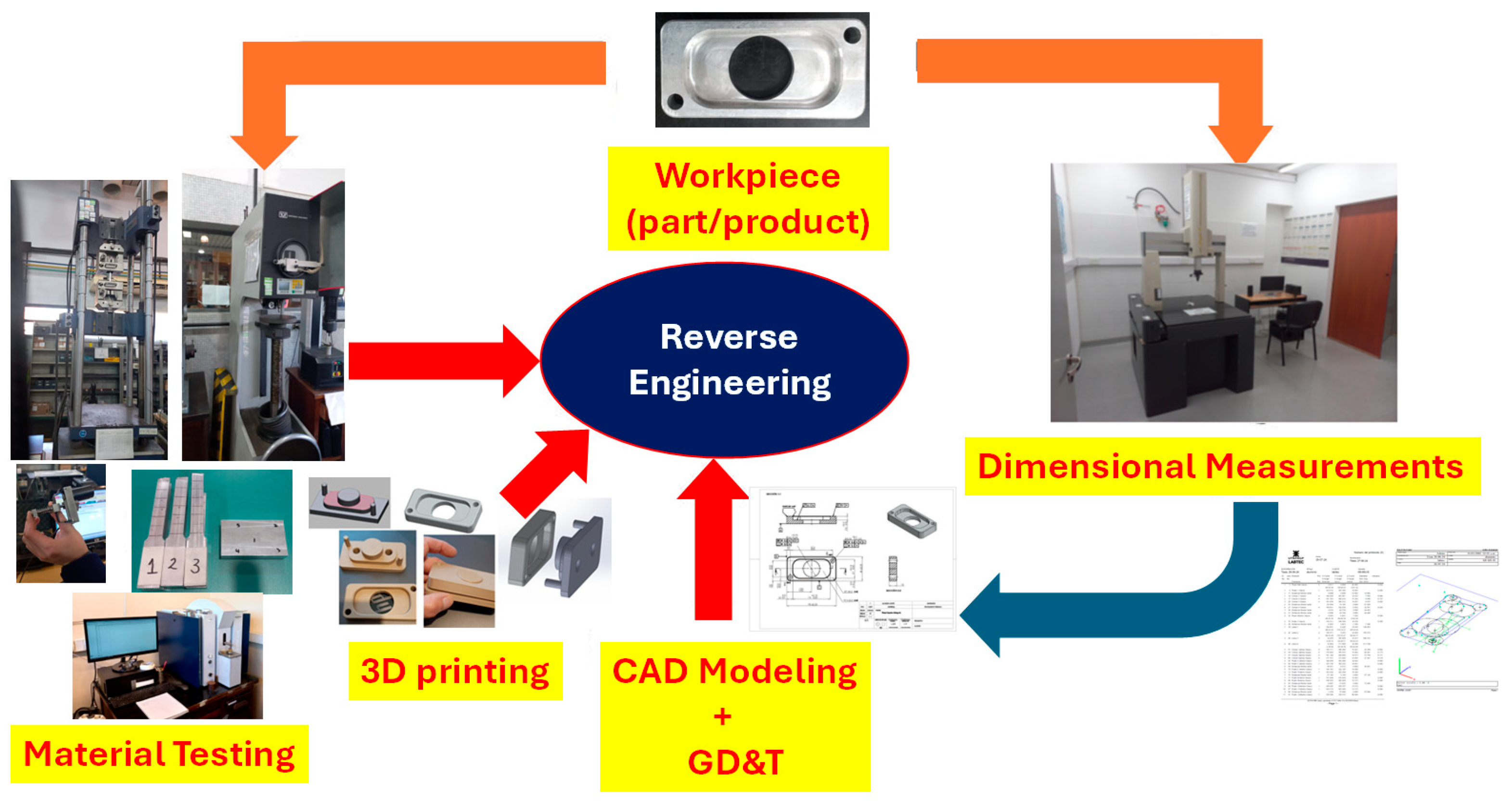
Figure 9.
Example CMM measurement report.
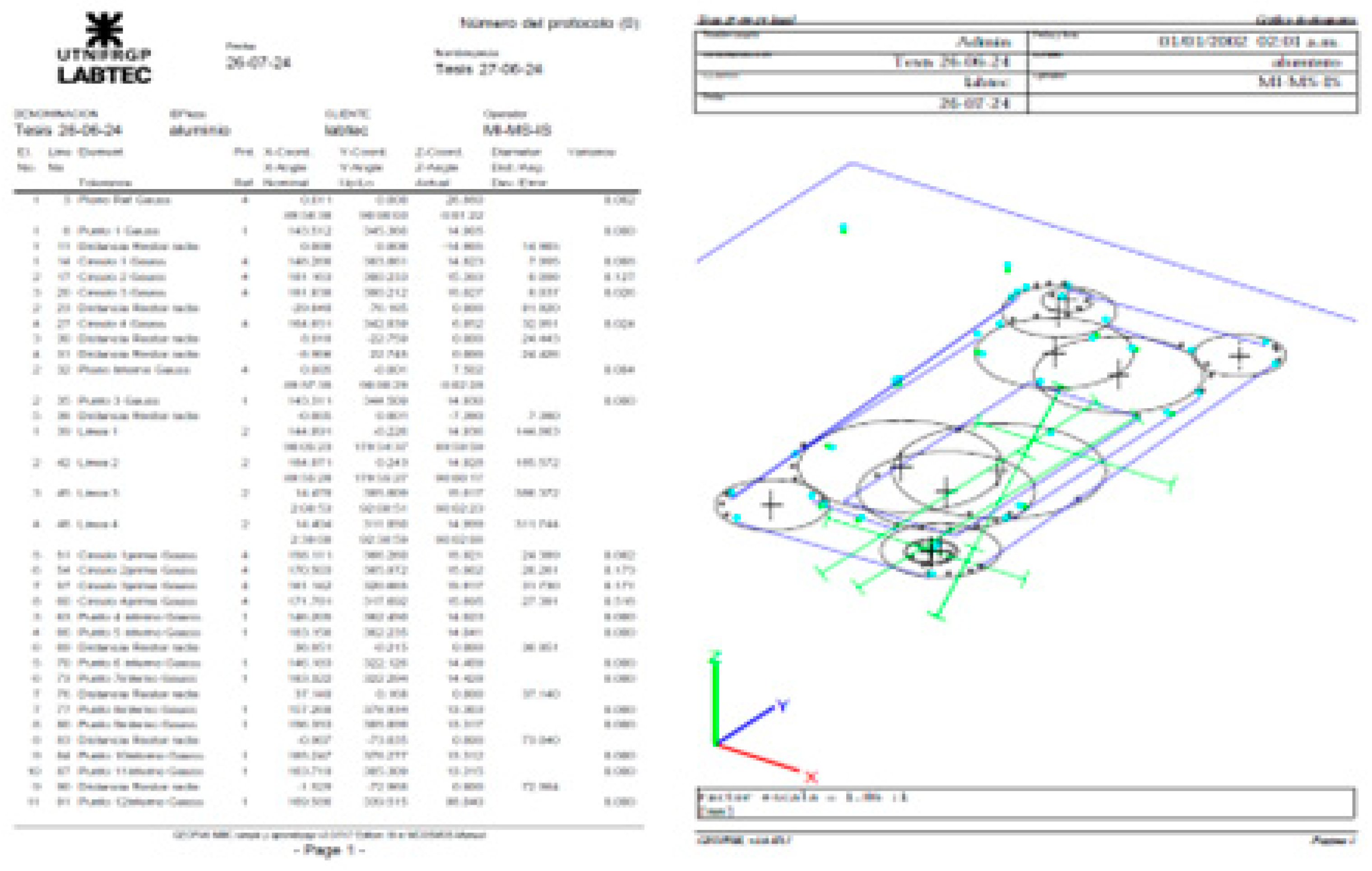
Figure 10.
Results of chemical analysis using spark optical emission spectroscopy.

Figure 11.
Test equipment and material testing -INTI´s devices.
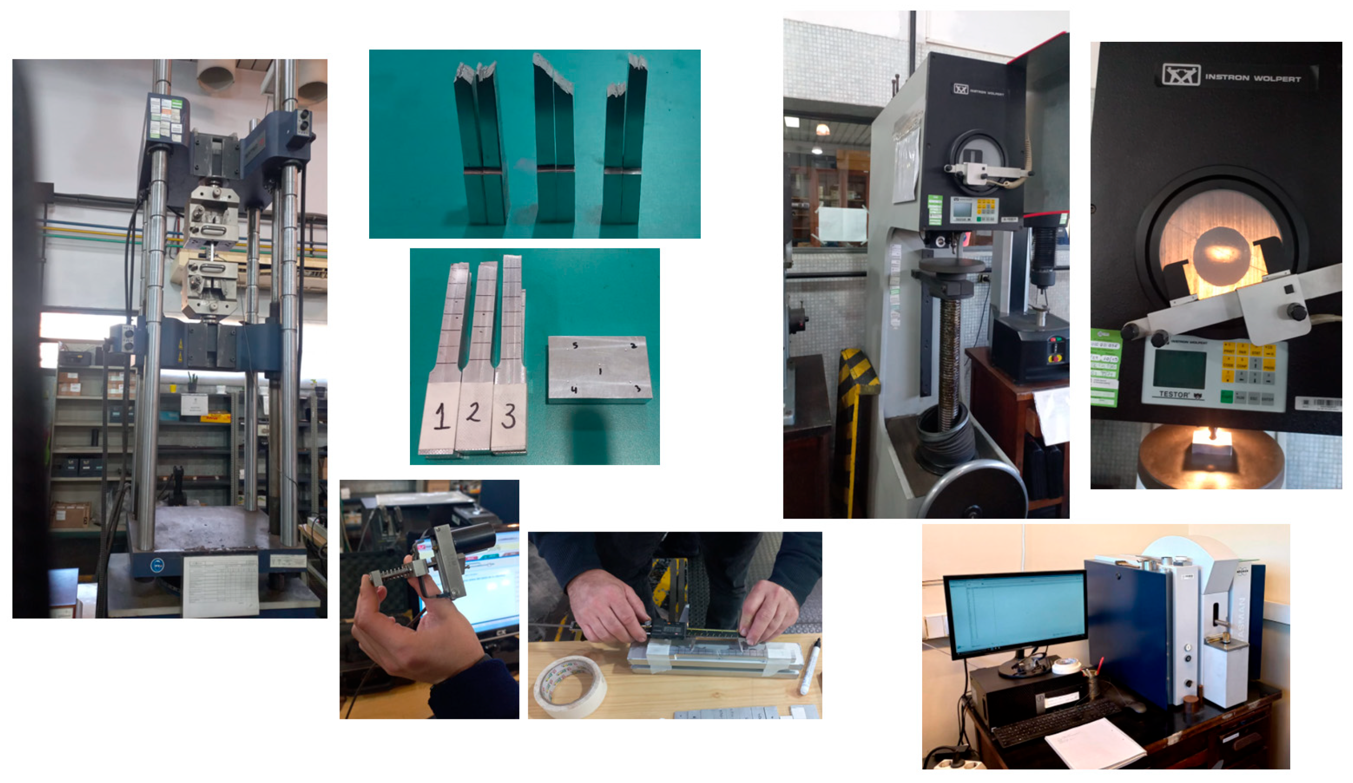
Figure 12.
Part prototypes and functional gauge in 3D printing.
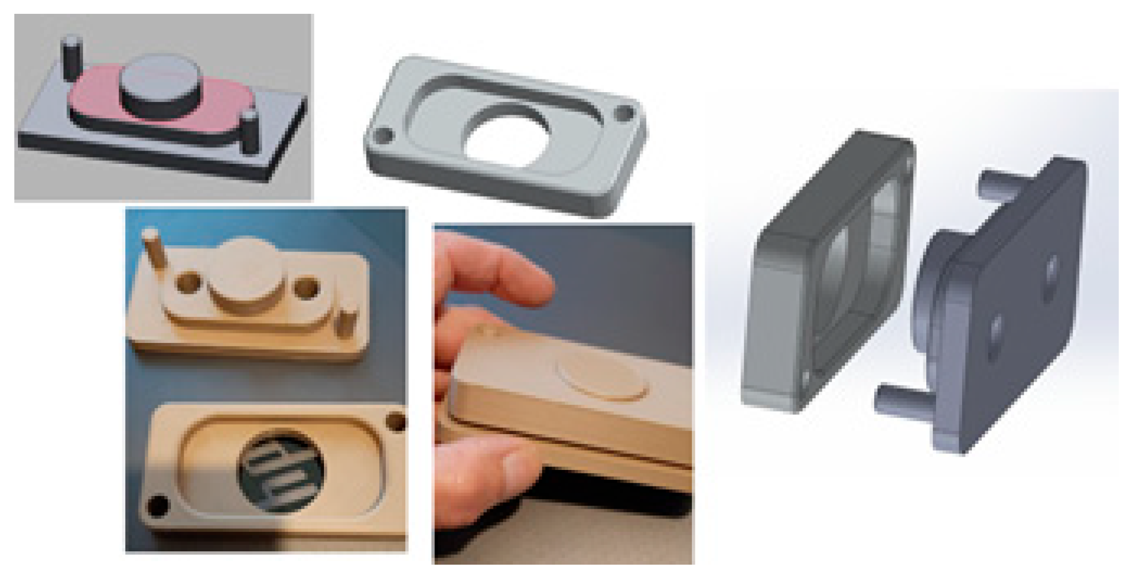
Figure 13.
CAD drawing system 3 planes and dimensioned part for 3D printer.
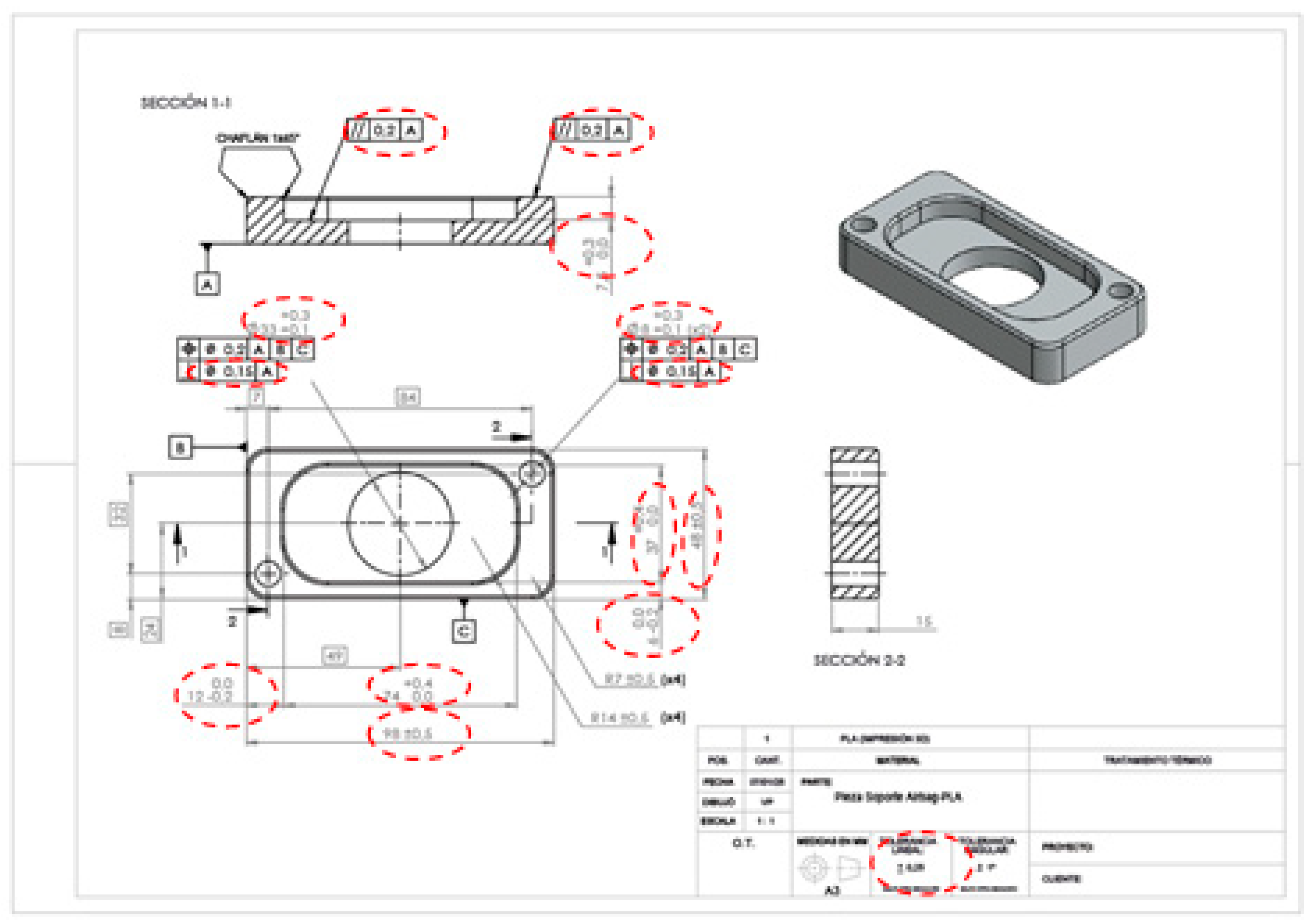
Figure 14.
CAD drawing system 3 planes and dimensioned part to be manufactured in AA7075 aluminum.
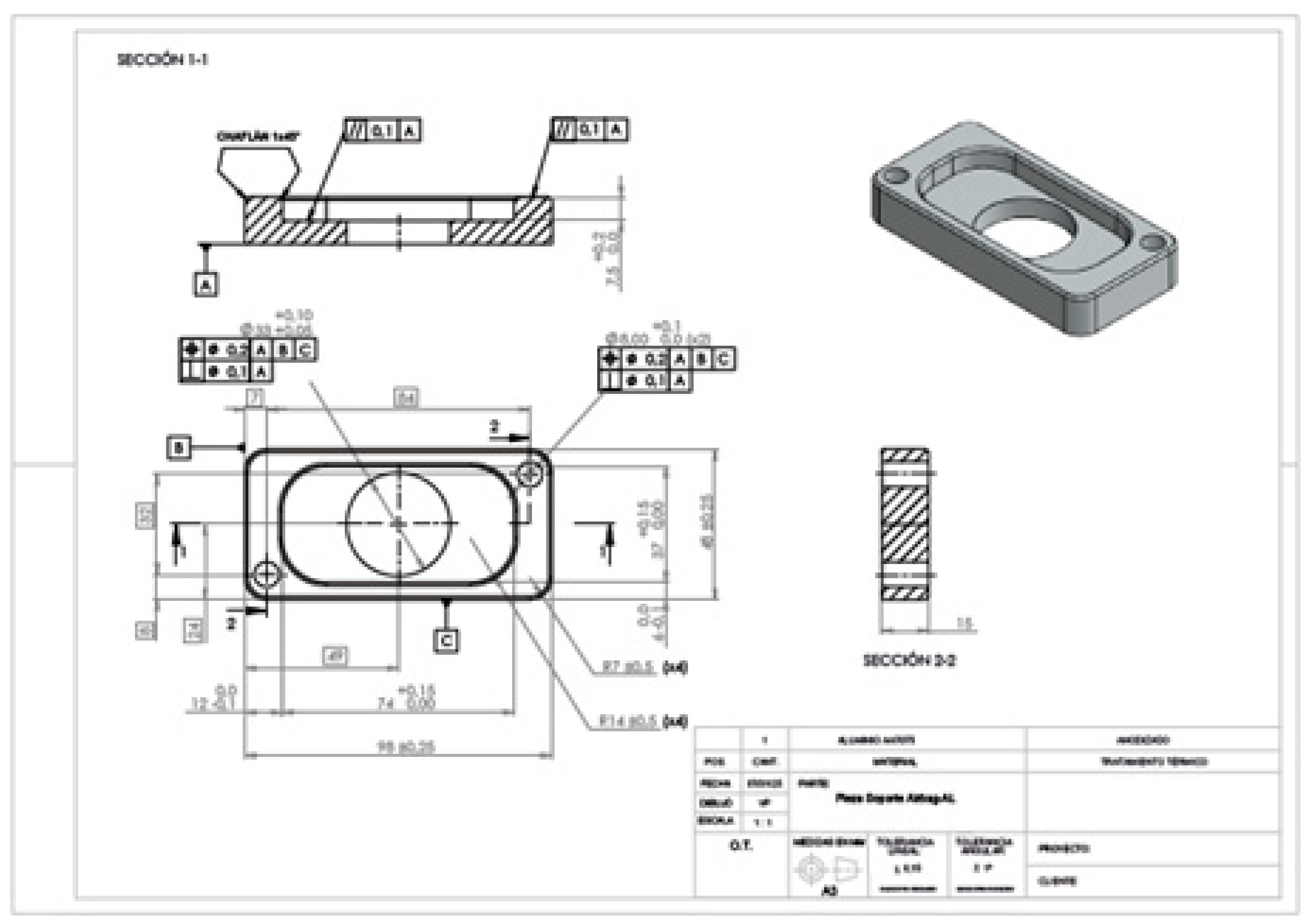
Figure 15.
CAD drawing system 3 planes and dimensioned part for 3D printer.
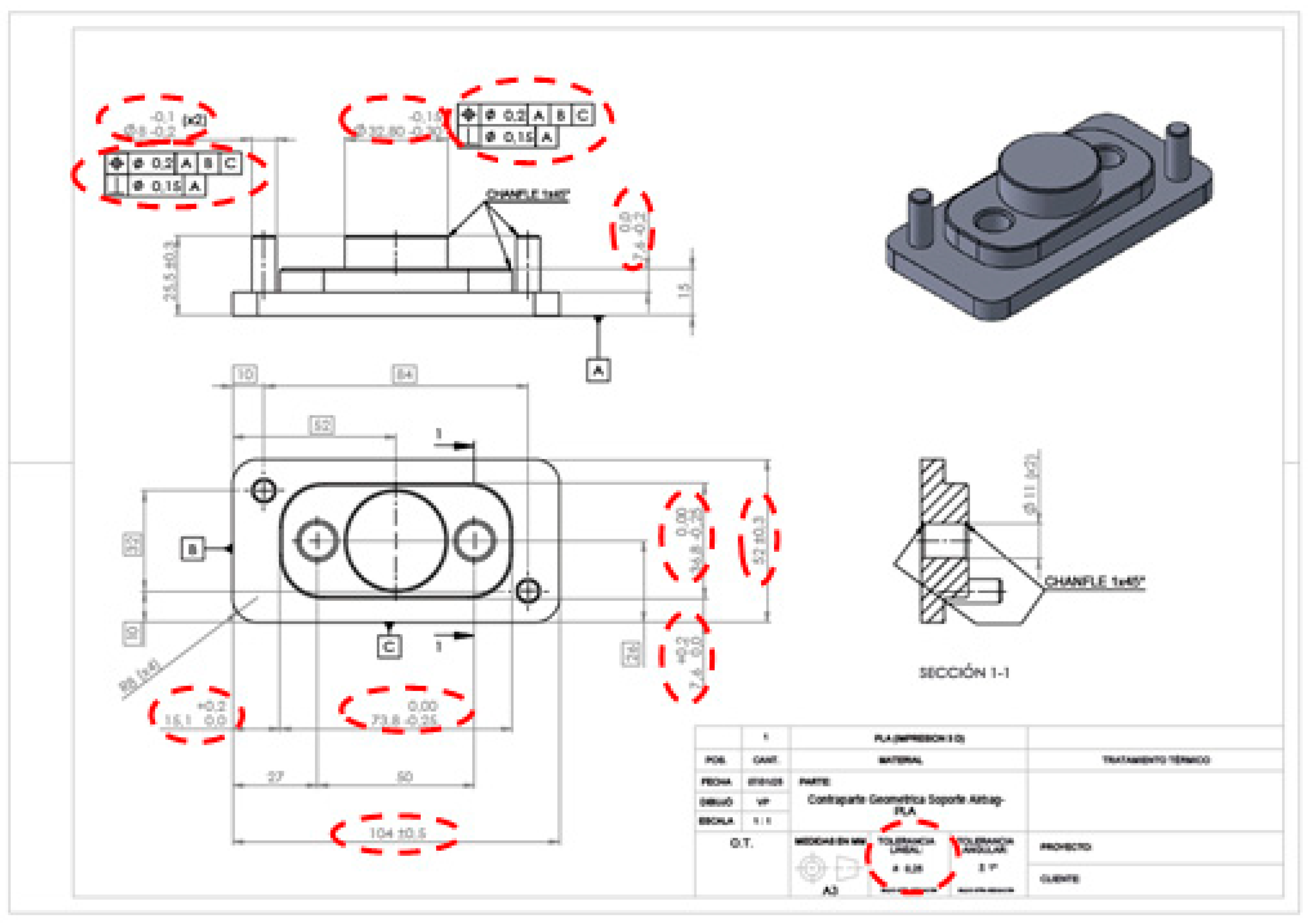
Figure 16.
CAD drawing system 3 planes and dimensioned functional gauge for machining in AA7075 aluminum.
Figure 16.
CAD drawing system 3 planes and dimensioned functional gauge for machining in AA7075 aluminum.
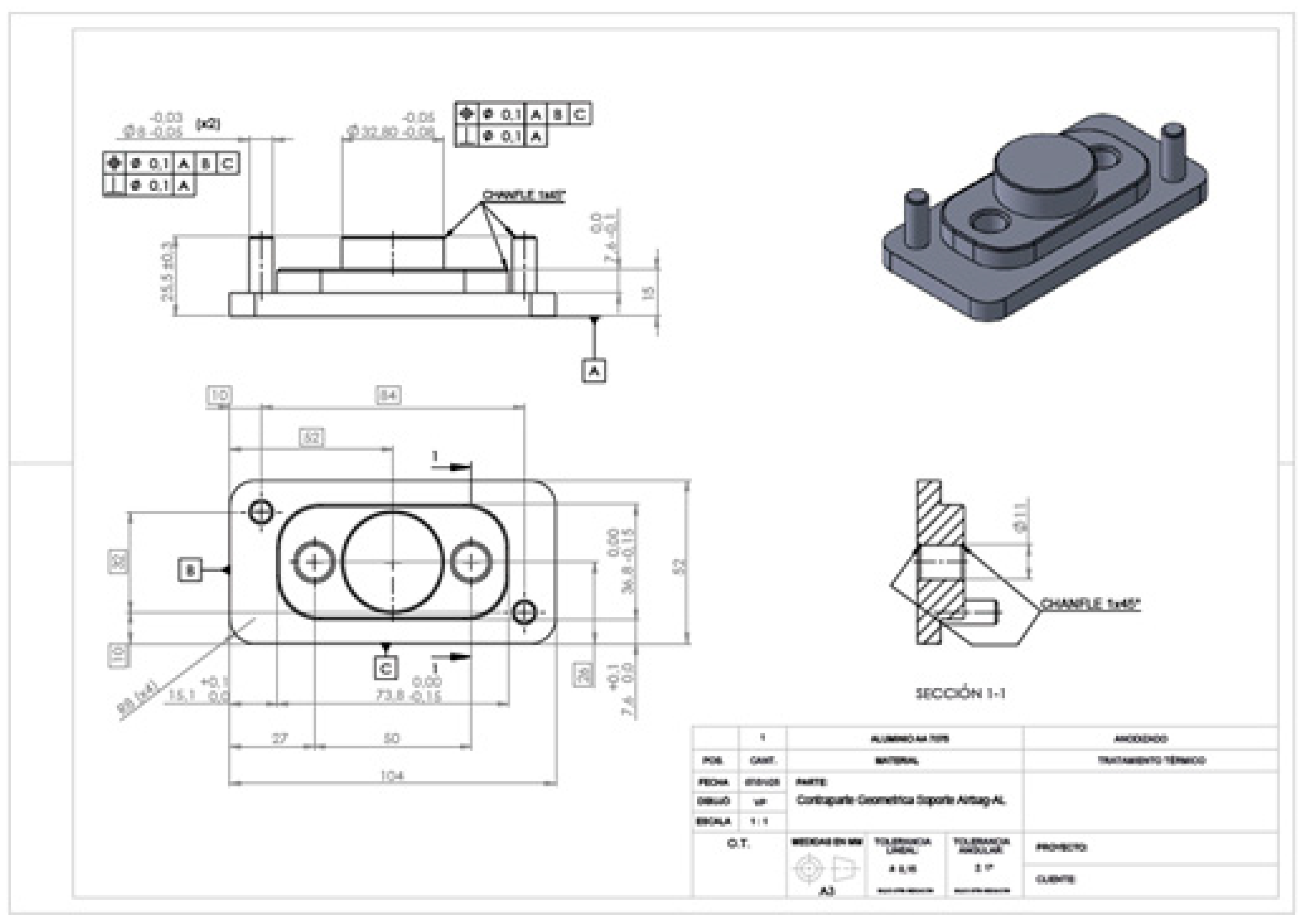
Figure 17.
Approval by functionality.
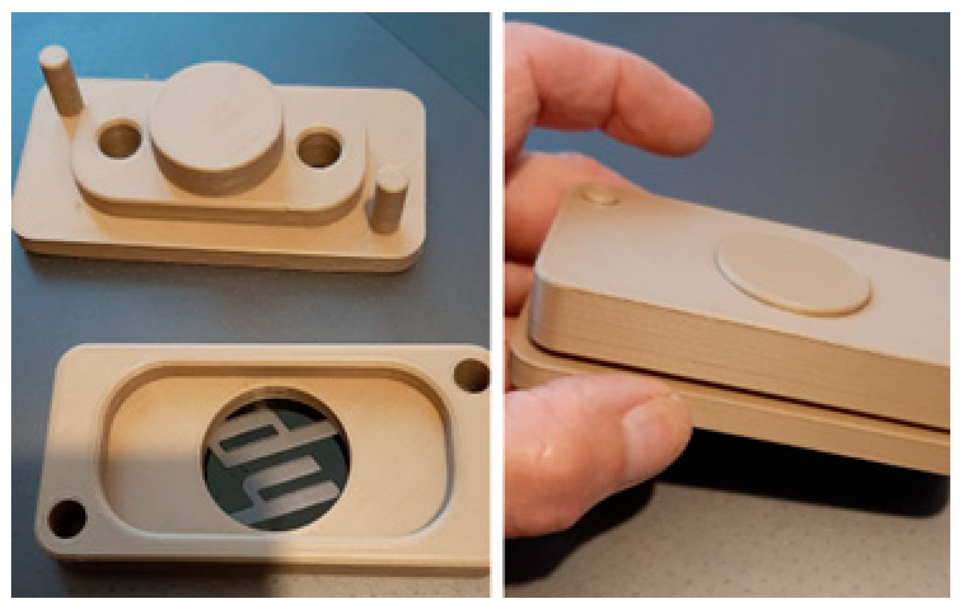
Figure 18.
Original part coupled with functional gauge printed in 3D printer.
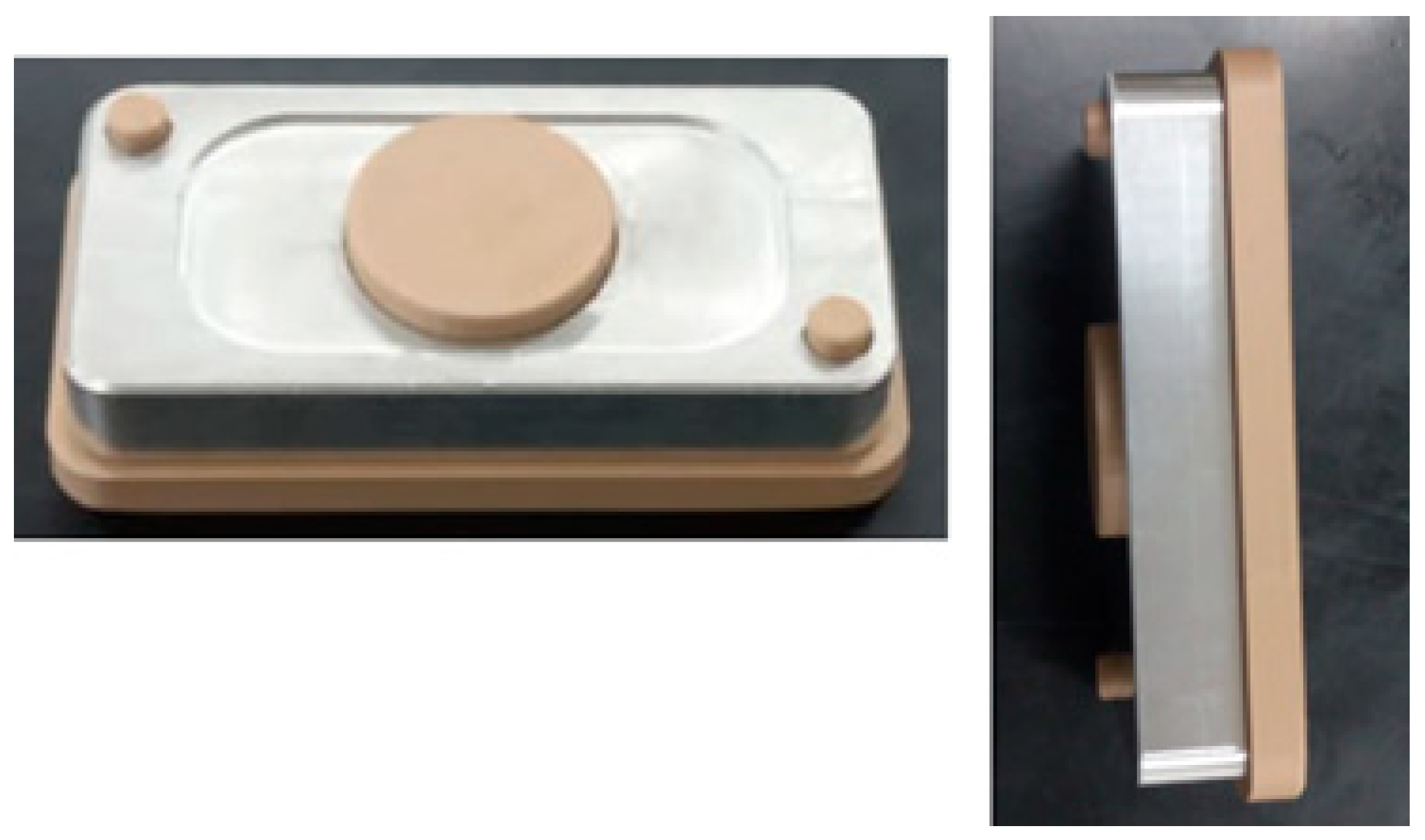
Figure 19.
Preliminary machining of part and functional gauge both in AA7075.
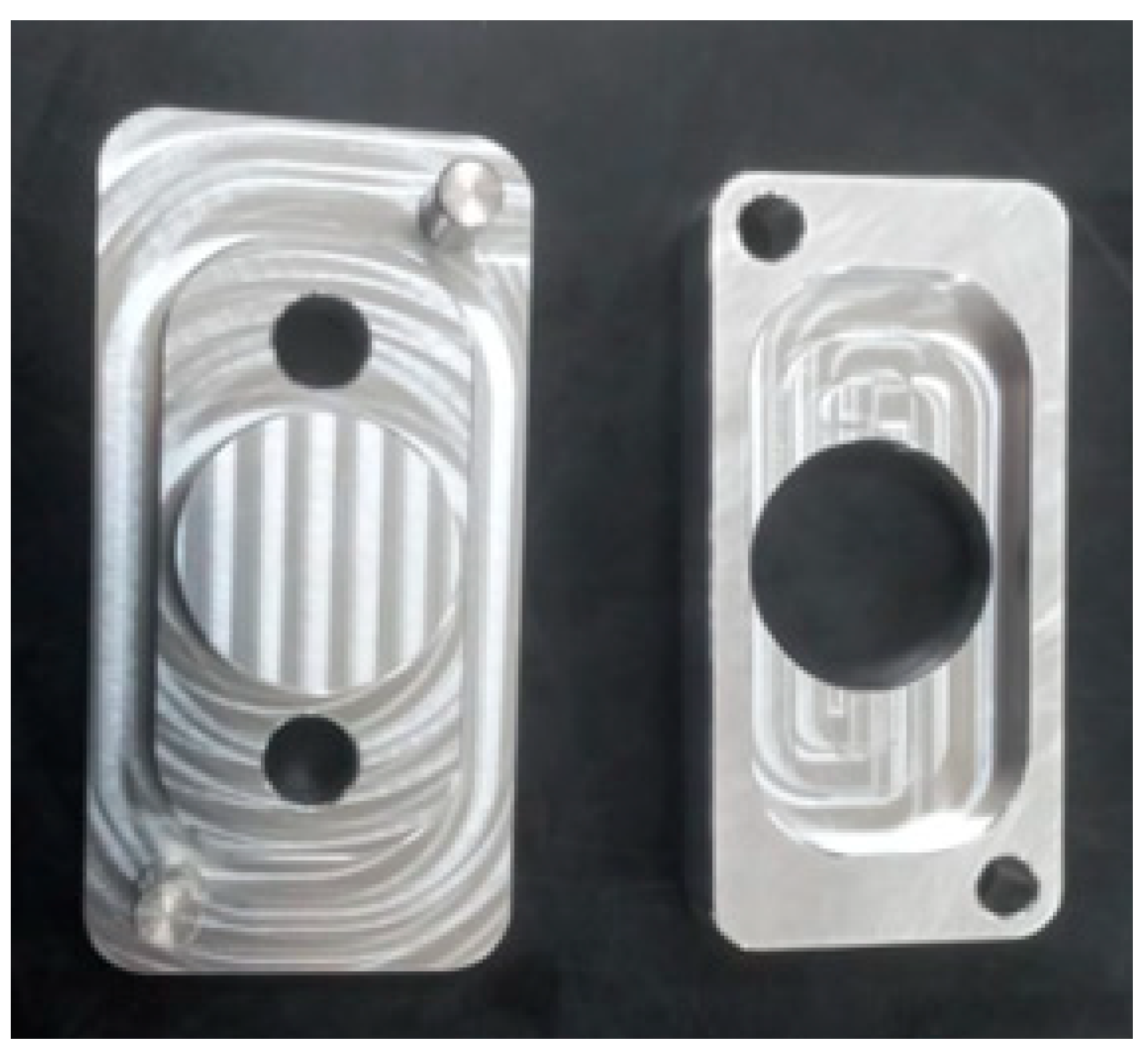
Figure 20.
Part on both sides and functional caliber, both in AA7075 with Blasting.
Disclaimer/Publisher’s Note: The statements, opinions and data contained in all publications are solely those of the individual author(s) and contributor(s) and not of MDPI and/or the editor(s). MDPI and/or the editor(s) disclaim responsibility for any injury to people or property resulting from any ideas, methods, instructions or products referred to in the content. |
© 2025 by the authors. Licensee MDPI, Basel, Switzerland. This article is an open access article distributed under the terms and conditions of the Creative Commons Attribution (CC BY) license (http://creativecommons.org/licenses/by/4.0/).
Copyright: This open access article is published under a Creative Commons CC BY 4.0 license, which permit the free download, distribution, and reuse, provided that the author and preprint are cited in any reuse.


