
Submitted:
09 August 2025
Posted:
11 August 2025
You are already at the latest version
Abstract
Microphysiological systems (MPS), such as organ-on-a-chip and body-on-a-chip platforms, have emerged as promising alternatives to animal testing for drug development and physiological research. The BioStellar™ Plate, an on-chip pump integrated microphysiological system, offers an open-access, multiorgan culture platform with built-in kinetic pump facilitating perfusion and circulation among six independent MO-MPS units. While effective in promoting convective flow, the current configuration cannot apply fluidic shear stress, an essential mechanical stimulus affecting cell behaviour and function, particularly in vascular, intestinal, and epithelial models. We developed two fluidic shear stress attachments for the BioStellar™ Plate to address this limitation. Flow dynamics were simulated using COMSOL Multiphysics to estimate shear stress levels within the system. The attachments were fabricated and validated through fluorescent bead tracking and biological assays. The flat-bottom Fluidic Shear Stress Attachment - Cell Desk (FSSA-D) is compatible with cell desk-based cultures. The Fluidic Shear Stress Attachment - Cell Culture Insert (FSSA-I) supports the culture of epithelial monolayers, enabling shear stress application across the basal membrane. Our results, including fluorescence imaging and TEER measurements, confirmed that both devices successfully enhanced barrier function under flow conditions. The reproducibility and consistent biological trends demonstrate the practicality of these attachments for mechanobiology research within MPS platforms.
Keywords:
microphysiological system (MPS)
; organs-on-a-chip
; BioStellar™ Plate
; fluidic shear stress (FSS)
1. Introduction
In drug development, typical experiments for drug discovery often use animal experiments and cell-based assay tests. Animal experiments have various issues, such as ethical considerations and species differences. Cell-based assays have issues with cultured cells that do not retain the organ's function in vitro. In recent years, in medicine and life sciences, microphysiological systems (MPSs), including organ-on-a-chip (OoC), are attracting attention as promising technologies that can reproduce in vivo-like tissue structures and fluid flow on microfabricated platforms. MPSs are increasingly being utilized to evaluate drug pharmacokinetics, toxicity, absorption, metabolism, and interorgan interactions under controlled in vitro conditions [1,2,3,4]. Multiorgan microphysiological systems (MO-MPS) enable the co-culture of multiple organ-derived cells, allowing the study of complex organ-organ interactions in real time and contributing to more accurate drug evaluation systems [5,6,7,8].
A key element for reproducing physiological conditions in MPS is the application of dynamic fluid flow to simulate blood circulation. Conventionally, syringe and peristaltic pumps have been used to generate perfusion flow; however, these external pump systems require complex tubing connections, present contamination risks and air bubbles, and consume large volumes of culture medium, increasing experimental costs and reducing throughput [9,10]. Various integrated pumping methods, including pneumatic pumps, membrane pumps, and gravity-based systems, have been developed to address these issues. However, many still involve complicated operations or closed-channel configurations that reduce usability for long-term culture and co-culture setups.
To overcome these limitations, a stirrer-based kinetic pump system was previously developed, which generates fluid circulation by rotating miniature magnetic stir bars embedded inside the culture device [11]. This technology led to the development of the Kinetic Pump Integrated Microfluidic Plate (KIM-Plate), which combines the stirrer-based kinetic pump with an open-access multiorgan microphysiological design [12]. The KIM-Plate comprises six independent MO-MPS units conforming to ANSI/SBS microplate standards, allowing direct use with commercially available cell culture inserts and disks. Open-top culture chambers of the KIM-plate simplify handling and enable the co-culture of multiple organ models. However, the KIM-Plate was made of black polymer, which made it difficult to check the stirrer rotation. Smitomo Bakelite developed the BioStellar™ Plate as a redesigned next-generation system based on the KIM-Plate concept to improve usability. The BioStellar™ Plate retains the exact kinetic pump mechanism and open-access design but employs transparent polystyrene for full compatibility with standard microscopy. While the BioStellar™ Plate provides continuous perfusion, it cannot apply controlled fluidic shear stress (FSS), which is an important factor influencing cellular morphology, differentiation, and barrier function under physiological conditions, because of the open-top culture chambers.
To address this limitation, we developed FSS loading attachments capable of guiding fluid flow and introducing controlled FSS onto epithelial cells cultured within the BioStellar™ Plate in this study. We designed and fabricated fluidic shear stress attachments (FSSAs) for the BioStellar™ Plate, conducted flow simulations, and verified their hydrodynamic behaviour through experiments. We successfully introduced controlled FSS during dynamic perfusion by applying these attachments to epithelial cell cultures. As a result, cells exposed to FSS showed improved growth and organization compared to static cultures, demonstrating the effectiveness of this approach in enhancing the BioStellar™ Plate for future microphysiological applications.
2. Materials and Methods
2.1. BioStellar™ Plate
The BioStellar™ Plate (Sumitomo Bakelite, Tokyo, Japan) consists of six independent MO-MPS units that conform to ANSI/SBS microplate standards (128 mm × 85 mm × 40 mm). Each unit features a pair of open-top culture chambers with the same diameter and configuration as standard 24-well plates, making it fully compatible with conventional cell culture protocols. Commercially available cell culture inserts and disks can be used directly within the plate without any modifications (Figure 1a). The entire plate body was fabricated from optically clear polystyrene (PS) using injection moulding. This enhances imaging compatibility and allows for seamless observation during culture. The microfluidic architecture connects each chamber pair by microchannels (1.0 mm wide × 0.3 mm high). These channels were positioned 1.2 mm above the bottom of the chamber. This construction limited direct fluid shear stress on cells.
Culture medium circulation was achieved through an embedded stirrer-based kinetic pump driven by a 3 mm × 0.2 mm stainless-steel stirrer bar. The clockwise rotation of a magnetic rotor beneath the plate generates forward flow through the main channel. In contrast, backflow through the secondary channel completes the loop, creating a continuous circulation system. The BioStellar™ Plate was designed to be used with a custom-built magnetic stirrer motor base that holds six magnetic rotor units, each driven by DC axial fans (108-AFB0412HHA-TA5F, Delta Electronics, Taipei, Taiwan). The base and its controller, produced by Microfluidic System Works, allow simultaneous control of rotor speeds, ensuring consistent and adjustable flow across all six MO-MPS units (Figure 1a). The system could reach rotation speeds of up to 6,500 rpm in its current configuration, allowing for a broad operational range that generates various flow rates suitable for both low-shear and high-shear experimental conditions.
2.2. Fluidic Shear Stress Attachments
To specifically introduce regulated FSS to cell cultures within the BioStellar™ Plate, we developed two customised fluidic shear stress attachments (FSSAs), each designed to accommodate different cell culture formats while maintaining compatibility with the BioStellar™ Plate (Figure 1b).
The Fluidic Shear Stress Attachment – Cell Desk (FSSA-D) was designed to support flat-surface cultures on the cell desk (Figure 1c, d, Figure S1a). The attachment features a centrally aligned straight microchannel that is 5.5 mm wide and 0.4 mm high after the installation of the cell desk. To ensure a consistent flow, the channel includes 35° slopes at both the inlet and outlet, effectively guiding fluid into the central region of interest. The entire FSSA-D body measures 15.9 mm in diameter and 17.0 mm in height, and it includes a concave slot (13.7 mm diameter, 0.3 mm depth) at the bottom to secure the cell desk (MS-92132, Sumitomo Bakelite, Tokyo, Japan) in place. Additionally, two grooves, each 0.5 mm deep and 7.6 mm wide, run along the sidewalls to accommodate PDMS sheets, creating a soft, watertight seal when interfaced with the BioStellar™ Plate. This channel configuration enables unidirectional laminar flow across the apical cell surface, ideal for mimicking physiological shear stimulation (Figure 1e).
The Fluidic Shear Stress Attachment – Insert (FSSA-I) was specifically engineered for cell culture inserts used in 24-well plate formats (Figure 1f, g, Figure S1b). It comprises a circular body with a 16.0 mm diameter and 5.5 mm height, featuring a central insertion port that was 4.0 mm high and 9.4 mm in diameter, securely accommodating the insert from above. The flow-guiding region beneath the insert is structured as a rectangular channel with a 9.3 mm width and 0.5 mm height, allowing medium to perfuse evenly along the basal surface of the membrane. The bottom structure of the FSSA-I was made from 1 mm thick acrylic, providing rigidity while maintaining optical clarity for microscopy. By redirecting flow beneath the membrane, the FSSA-I enables localised FSS application to the basal side of epithelial layers, thereby replicating dynamic microenvironments similar to those found in intestinal, renal, or vascular systems (Figure 1h).
2.3. Fabrication of the FSSAs
FSSAs were fabricated using a high-resolution 3D printer Formlabs Form 3B+ (PKG-F3B-COMPLETE-EW-1, Formlabs, Massachusetts, USA) with BioMed Clear resin (RS-F2-BMCL-01, Formlabs, Massachusetts, USA), a biocompatible photopolymer suitable for cell culture applications. The FSSAs’ geometries were designed using AutoCAD (Autodesk, California, USA) and exported as STL files, which were subsequently processed in PreForm software (Formlabs, Massachusetts, USA). The models were printed using default settings with a layer thickness of 50 µm to achieve high-dimensional precision and smooth surface quality suitable for microfluidic use. Following printing, the attachments were washed in isopropyl alcohol (IPA) using the Form Wash (FH-WA-02, Formlabs, Massachusetts, USA) for 15 minutes to remove uncured resin from channel structures and surfaces. The printed parts were then post-cured using Form Cure (FH-CU-01, Formlabs, Massachusetts, USA) at 60 °C for 30 minutes, ensuring complete crosslinking and mechanical stability of the material. The cured attachments underwent a detailed multi-step solvent-washing protocol designed to remove toxins from the printed material and prepare it for further biological use. Initially, each FSSA was submerged in acetone and cleaned with an ultrasonic washer for 60 minutes.-After the acetone wash, the attachments were rinsed in IPA for 30 minutes using an ultrasonic washer to ensure that any traces of acetone were thoroughly removed. The attachments underwent three consecutive washes, each lasting 30 minutes, with ion-exchanged water, again using an ultrasonic washer. Finally, the attachments were sterilized by autoclaving at 120 °C for 20 minutes. This high-temperature process eliminated any potential microbial contamination. After autoclaving, the FSSAs were allowed to cool overnight to minimize the risk of cracking caused by thermal stress, ensuring they were safe and ready for further applications.
The bottom of FSSA-D was installed using the cell desk and double-sided tape, forming a connected perfusion chamber. To reinforce the lateral fit and maintain structural alignment within the BioStellar™ Plate, a 0.5 mm thick PDMS sheet was applied along the sidewall’s grooves of the attachment (Figure 1e). Conversely, the FSSA-I was assembled onto a custom-fabricated acrylic base to accommodate a cell culture insert (Transwell®, 3450, Corning, New York, USA) (Figure 1h). The components were joined using double-sided tape to ensure stable integration.
Following assembly, the FSSAs underwent gas sterilization to ensure sterility across all contact and interface surfaces. Before beginning biological experiments, the FSSAs were stored for at least one week to remove any potential cytotoxicity from residual sterilant gases.
2.4. Numerical Simulation in Flow
To evaluate the flow characteristics within the BioStellar™ Plate, 3D models of the cell culture chamber, FSSA-D, and FSSA-I were constructed using COMSOL Multiphysics (COMSOL, Stockholm, Sweden). The simulation domain included a cylindrical chamber measuring 16.4 mm in diameter and 4.7 mm in height, with two fluidic channels on opposite ends. Each channel measured 1.0 mm in width and 0.5 mm in height, functioning as the inlet and outlet. The working fluid was modelled using water properties at 37°C, with slight modifications to reflect physiological conditions accurately. Simulations were conducted under five different inlet flow velocities to analyse variations in velocity distribution across both FSSA designs.
2.5. Flow Observation
To experimentally validate flow simulations and characterise flow behaviour, we performed particle tracking velocimetry using fluorescent microbeads (10 μm in diameter, 1.1 × 10⁸ particles/mL, 18142, Polyscience, Illinois, USA) as flow tracers. Instead of using the full BioStellar™ Plate, we employed a custom-fabricated PDMS-based open-top culture chamber model that resembled the BioStellar™ Plate architecture. The chamber model retained the essential features of the BioStellar™ Plate, including inlet and outlet water channels and a single cell culture chamber, but also included a glass-bottom to facilitate high-resolution imaging (Figure S2).
The FSSAs were mounted onto the chamber model to replicate the in-situ flow environment. Flow was driven by two syringe pumps programmed to mimic the pulsatile perfusion behaviour generated by the BioStellar™ Plate. We recorded bead movement in the central region of each attachment using an Olympus IX71 (Olympus Corporation, Tokyo, Japan) inverted fluorescence microscope paired with a video camera (FDR-AX700, Sony, Tokyo, Japan) operating in super slow-motion mode (240 fps).
The captured videos were analysed using FlowExpert64 software (Katokoken, Kanagawa, Japan), a particle image velocimetry (PIV) platform, to quantitatively extract flow velocity fields and estimate local FSS in the attachment channels. The Supplementary Information includes a representative video of the microbead flow behaviour (Figure S3, Video S1, S2).
2.6. Estimation of FSS
where μ is the viscosity of water at 37 °C (0.6913 mPa·s), u is the average flow velocity (m/s), and h is the channel height (m).
It is worth noting that the flow velocity obtained through microscopy reflects the peak velocity at the centre (z-axis) of the microchannel rather than the average velocity across the entire cross-section, an important distinction when calculating FSS. Additionally, while FSS was calculated using standard SI units (Pascal, Pa) via the equation, the values reported throughout the results section are expressed in dyne per square centimetre (dyn/cm²) for consistency with the biological literature. For reference, 1 Pa is equivalent to 10 dyn/cm². In cylindrical channels, the average velocity is generally assumed to be half the maximum. However, this relationship does not carry over to rectangular channels like the FSSAs. To address this, we used ANSYS Fluent (Ansys, Pennsylvania, USA) to simulate the precise channel geometries of both FSSA-D and FSSA-I and to determine the ratio between maximum and average velocities. From these simulations, correction factors of 1.55 for FSSA-D and 1.56 for FSSA-I were obtained and applied to convert the measured peak velocities into more accurate average velocities (Figure S4).
2.7. Cell Culture
Human epithelial colorectal adenocarcinoma cells (Caco-2, ATCC, Virginia, USA) were cultured in 100 mm culture dishes (3020-100, Iwaki, Shizuoka, Japan) using Dulbecco’s Modified Eagle Medium (DMEM, 11885092, Thermo Fisher Scientific, Massachusetts, USA). The medium contained 1 g/L glucose and 25 mM HEPES, supplemented with 10% fetal bovine serum (FBS, 10270-106, Thermo Fisher Scientific, Massachusetts, USA), 1% antibiotic-antimycotic (AA, 161-23181, Fujifilm Wako Pure Chemical Corporation, Osaka, Japan), and 1% non-essential amino acids (NEAA, 11140-050, Thermo Fisher Scientific, Massachusetts, USA). Cultures were maintained at 37°C in a humidified incubator with 5% CO₂. The culture medium was replaced every two days throughout the expansion and experimental culture periods to maintain nutrient balance and cell viability.
In the FSSA-D configuration, the FSS group was cultured using dynamic perfusion within the FSSA placed on the cell desk. The control group was cultured on cell desks in standard well plates without the FSSA under conventional static conditions. This configuration allowed for a direct comparison between conventional static culture and the effect of applied FSS generated by the FSSA-D. In the FSSA-I configuration, cells were cultured on the basal side of a microporous membrane of a cell culture insert (Transwell®, 3450, Corning, New York, USA) in both the control group and the FSS group. This configuration allowed access to the basal membrane surface for FSS exposure.
Two types of extracellular matrix (ECM) coatings were prepared. For FSSA-D, a Collagen Type I-P solution was prepared by mixing 1 mL of Collagen Type I-P (634-00663, Nitta Gelatin, Osaka, Japan) with 9 mL of ultrapure water, followed by the addition of 10 µL of hydrochloric acid to adjust the pH to approximately 3. The FSSA-D was submerged in this solution and incubated at 37°C for 1 hour to allow for uniform coating of the microchannel surfaces. For the FSSA-I, Matrigel (354230, Corning, New York, USA) was used at a 1:25 dilution in a cold medium and applied solely to the membrane surface of the cell culture insert. The inserts were incubated at 37°C for 1 hour to ensure a consistent ECM coating.
In case of cell seeding for FSSA-D, Caco-2 cells were seeded directly into the coated channels at 2 × 10⁵ cells/cm². Approximately 80 µL of the cell suspension was introduced into each channel, followed by a 5-hour pre-culture period in a 12-well plate containing the surrounding culture medium. After sufficient cell attachment, the FSSA-D were transferred into the BioStellar™ Plate to initiate perfusion culture.
In case of cell seeding for FSSA-I, inverted seeding facilitated basal membrane culture. The cell culture inserts were placed upside down in a 12-well plate, and 2 × 10⁵ cells/cm² of Caco-2 cells were seeded onto the basal membrane surface using a custom-fabricated PDMS cup-like holder to retain the seeding medium. Each insert received 100 µL of medium and was incubated inverted for 3 hours for cell attachment. Afterwards, the inserts were returned to their upright position and pre-cultured in a standard 24-well plate for 1 day, then transferred into the BioStellar™ Plate system for perfusion culture.
2.8. TEER Measurement
For the FSSA-I experiments, epithelial barrier formation was assessed using a transepithelial electrical resistance (TEER) measurement system (Millicell ERS-2, MERS00002, Merck Millipore, Massachusetts, USA). Chopstick electrodes were positioned with one probe in the apical compartment and the other in the basal compartment. TEER values were calculated by subtracting the background resistance of a blank insert from the resistance measured in the cell-seeded insert. TEER measurements were performed before each medium change to monitor barrier development under consistent conditions.
2.9. Fluorescence Staining and Imaging
To visualize cell morphology and tight junction formation, cultured cells were prepared for fluorescence staining. Cells were rinsed with PBS (+) (D8662-500mL, Sigma-Aldrich, Massachusetts, USA) and fixed using 4% paraformaldehyde (163-20145, Wako Pure Chemical Corporation, Osaka, Japan) for 15 minutes. After rinsing with PBS (-) (D1408-500mL, Sigma-Aldrich, Massachusetts, USA) the cells were permeabilized with 1% Triton X-100 (02081155, KISHIDA CHEMICAL, Osaka, Japan) for 10 minutes, followed by additional washes with PBS (-). Samples were blocked using 1% BSA/PBS for 1 hour at room temperature.
Tight junctions were stained using a primary ZO-1 antibody (21773-1-AP, Proteintech, Illinois, USA) diluted 1:500 in 1% BSA/PBS and incubated overnight at 4°C in the dark. The next day, cells were washed and stained with a combined solution of DAPI (340-07971, DOJINDO, Kumamoto, Japan) (1:1000), Alexa Fluor 488 Phalloidin (PHDG1, Cytoskelton.inc., Colorado, USA) (14 µM), and Alexa 568 secondary antibody (A10042, Thermo Fisher Scientific, Massachusetts, USA) (1:1000), all diluted in 1% BSA/PBS. The staining solution was applied to the inserts and incubated for 1 hour at room temperature. After the final washes with PBS (-), the samples were stored in PBS (-) and imaged using a confocal laser microscope at the Tokai University Imaging Center for Advanced Research.
2.10. Statistical Analysis
All data are presented as the mean ± standard deviation (SD) derived from a minimum of three independent experiments. Statistical analysis was conducted using Student's t-test, with statistical significance determined at a threshold of * p < 0.05, ** p < 0.01, *** p < 0.005.
3. Results
3.1. Flow Analysis in FSSAs
To evaluate the fluid dynamics within the BioStellar™ Plate and assess the performance of the developed FSSAs, we conducted a combination of finite element method (FEM) simulations and experimental flow validation. Figure 2a illustrates the simulated BioStellar™ Plate, highlighting the inlet and outlet flow paths, as well as the analysis region located at the bottom of the culture chamber. The open-top culture chamber format and internal geometry of the unmodified chamber limited control over directional flow. The XY-plane velocity cross-section showed highly non-uniform flow, with low-velocity zones at the centre (Figure 2a, b left), resulting in minimal shear exposure for centrally located cells (Figure S5, Figure S6, Table S1).
To evaluate the functionality of the FSSAs, simulations were conducted under the same conditions as those of the BioStellar™ Plate. Simulation results demonstrated that both FSSA-D and FSSA-I effectively redirected the recirculating medium into well-controlled, parallel laminar flow regimes (Figure 2a middle and right). For FSSA-D, the flow was guided through a narrow, straight channel (channel height: 0.4 mm), resulting in uniform, unidirectional laminar flow across the culture surface. The velocity profile confirmed even shear exposure across the entire width of the channel (Figure 2b middle). Similarly, the FSSA-I attachment redirected the flow beneath the insert membrane, generating consistent laminar flow along the basal surface through a 0.5 mm high channel (Figure 2b right). These designs successfully converted native circulation into stable, physiologically relevant FSS profiles.
Experimental validation was conducted using fluorescent bead tracking to measure shear stress at various flow rates: 54, 100, 150, 200, and 400 µL/min. For the FSSA-D configuration, experimental and simulation values showed good agreement at flow rates of 54, 100, and 150 µL/min, with no significant differences observed. However, notable discrepancies emerged at 200 and 400 µL/min, where experimental values were substantially lower than simulated predictions.
In contrast, the FSSA-I configuration exhibited consistent discrepancies between experimental and simulation values across all tested flow rates (Figure 2c, d). These discrepancies stem from the inherent difference between idealized simulation conditions and real fabrication tolerances. The simulations assume perfect dimensional accuracy, while the experimental setup involves fabricated components with dimensional variations. The FSSAs were 3D printed and assembled by hand, and the BioStellar™ Plate itself does not possess perfectly precise dimensions. The different discrepancy patterns between FSSA-D and FSSA-I likely reflect their distinct sensitivities to dimensional imperfections. FSSA-D's stagnation region design appears more tolerant to minor dimensional variations at lower flow rates, with fabrication effects becoming prominent only at higher velocities. FSSA-I's geometry may be inherently more sensitive to dimensional deviations, resulting in consistent flow pattern alterations across all tested flow rates.
From the validated flow data, corresponding FSS values were calculated. In the FSSA-D system, a rotation speed of 5,500 rpm generated an approximate flow rate of 89 µL/min, yielding a calculated FSS of 0.02 dyn/cm² (Figure 2c). For FSSA-I, a rotation speed of 6,500 rpm produced approximately 104 µL/min, resulting in a comparable FSS of 0.02 dyn/cm² (Figure 2d). These conditions were selected based on prior studies indicating that low-level FSS in this range supports epithelial differentiation, barrier formation, and polarization in Caco-2 cells.
The findings indicate that FSSA-D and FSSA-I enabled the BioStellar™ Plate to generate stable and adjustable FSS environments. This system provides a platform for investigating FSS-dependent cellular responses under physiologically relevant flow conditions.
3.2. Cell Culture Evaluation in the FSSA-D
Following the characterisation of fluid dynamics, the biological impact of FSS was evaluated using the FSSA-D configuration. Two conditions were implemented: a static control (cells cultured on the cell desk and placed directly in the well plate without flow), and a physiologically relevant low FSS condition (5500 rpm, 89 µL/min, 0.02 dyn/cm²). This comparison enabled the assessment of shear stimulation effects while ensuring comparable cell viability between groups. Caco-2 cells were pre-cultured in FSSA-D for 5 hours in standard 12-well plates before being transferred into the BioStellar™ Plate for dynamic culture over five days.
Fluorescence staining with DAPI (nuclei), Phalloidin (F-actin), and ZO-1 (tight junction protein) was performed on day 5 to evaluate cellular morphology, cytoskeletal arrangement, and junctional organisation. Confocal images confirmed that both static and FSS conditions supported the formation of confluent Caco-2 monolayers with well-developed cytoskeletal structures and continuous ZO-1 expression patterns (Figure 3a). No detachment or major morphological abnormalities were observed in either group, indicating that both conditions enabled stable short-term culture. A slightly enhanced continuity of ZO-1 signal was noted under FSS conditions, potentially reflecting FSS-mediated support for tight junction maturation, consistent with previously reported mechanosensitive pathways [15,16,17], though these differences remained subtle and within biological variation.
Vertical cross-sections of DAPI and Phalloidin-stained samples revealed further distinctions in epithelial architecture (Figure 3b). Cells exposed to FSS developed thicker, columnar morphologies with well-defined apical-basal polarity, while static conditions yielded shorter and less polarised cell layers. Quantitative analysis showed a significant increase in cell thickness under FSS, with averages rising from 20 µm (static) to 30 µm (FSS) (Figure 3c).
3.3. Cell Culture Evaluation in the FSSA-I
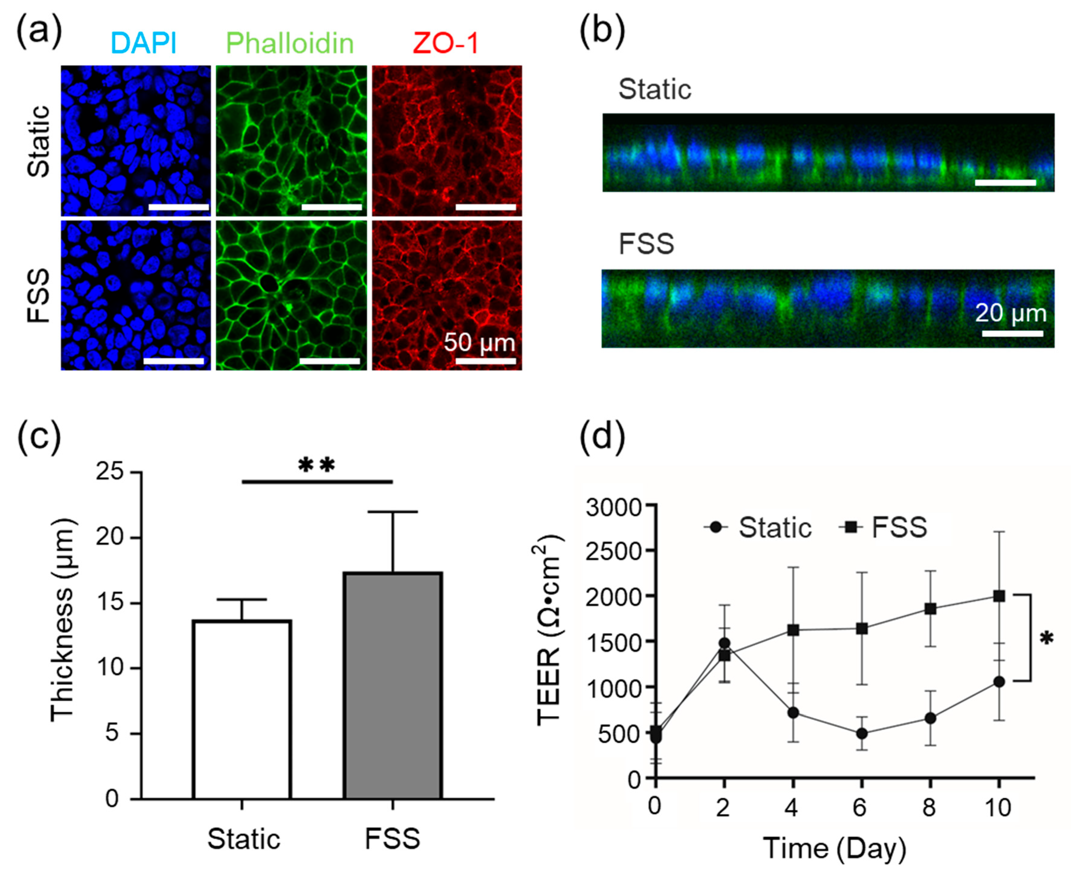
The biological response of epithelial cells under controlled FSS was evaluated using the FSSA-I configuration. Dynamic perfusion at 6,500 rpm with the BioStellar™ Plate system produced a flow rate of approximately 104 µL/min, corresponding to an estimated 0.02 dyn/cm² FSS. Caco-2 cells were cultured under static and FSS conditions for 10 days, with fluorescence staining evaluating morphology and junctional organization. Confocal images stained for DAPI, Phalloidin, and ZO-1 confirmed confluent monolayers in both groups, and well-developed cytoskeletal architecture with continuous ZO-1 patterns; no detachment or structural abnormalities were evident, indicating support for viable long-term culture (Figure 4a). Vertical cross-sectional imaging of DAPI and Phalloidin-stained samples showed that, under FSS conditions, cells displayed greater apical-basal polarity and increased vertical height than static controls (Figure 4b, Figure S7). Quantitative analysis showed a statistically significant increase in epithelial thickness under FSS (P < 0.01): from ~14 µm (static) to ~17 µm (flow) (Figure 4c). Despite comparable morphology, TEER (transepithelial electrical resistance) measurements over 10 days revealed functional differences in barrier integrity: static conditions led to inconsistent TEER after day 2, while FSS induced a steady increase, stabilising at higher levels (Figure 4d).
4. Discussion
In this study, we developed and evaluated two FSSAs, FSSA-D and FSSA-I, for integration with the BioStellar™ Plate microphysiological system platform. These attachments enable the precise application of low-level FSS to epithelial cell cultures. Our combination of computational simulations and experimental flow validation demonstrated that both attachments effectively transformed the previously irregular recirculating flow within the BioStellar™ Plate chamber into stable, uniform laminar flow environments [18]. The controlled hydrodynamic conditions produced by these devices facilitated reproducible FSS loading.
Biological assessments utilizing Caco-2 cells indicated that static and FSS conditions using both FSSA-D and FSSA-I supported the formation of a confluent monolayer. Cells exposed to controlled FSS exhibited enhanced transepithelial electrical resistance (TEER), increased epithelial layer thickness, and improved barrier function compared to static controls. The FSS of 0.02 dyn/cm² in the cell culture experiment is a physiologically relevant mechanical stimulus closely mimicking the in vivo environment for intestinal epithelial cells [19,20,21,22]. This value has been reported as optimal in prior studies: for example, Shin et al. demonstrated that flow-dependent physical cues control human intestinal morphogenesis in microengineered gut-on-chip systems, while other research has shown that physiological shear stress enhances differentiation, mucus formation, barrier integrity, and 3D tissue architecture at this stress level [19,20,21,22,23,24]. Most notably, quantitative functional assessment of epithelial barrier properties, as measured by TEER, was possible in the FSSA-I configuration [25]. Here, application of FSS resulted in a progressive increase and stabilisation of TEER values, indicative of tighter junctions and improved barrier integrity [26,27]. These results corroborate extensive literature indicating that mechanical cues from physiologically relevant FSS accelerate epithelial maturation, enhance cytoskeletal and junctional organisation, and support the development of more predictive and robust in vitro intestinal models [19,20,21,22,28]. These findings confirm that low-level FSS improves architecture and barrier function, demonstrating the effectiveness of the BioStellar™ Plate system with FSSAs and its reliability in modelling physiological epithelial responses [24,29,30,31].
In conclusion, incorporating these FSSAs significantly enhances the functional capabilities of the BioStellar™ Plate platform by introducing controllable mechanical stimulation while ensuring compatibility with standard culture formats. Our FSSAs provide a straightforward and accessible approach for mimicking physiologically relevant flow conditions in vitro. Our attachments help investigate FSS-mediated effects on epithelial cell function and intestinal barrier models within microphysiological systems.
Supplementary Materials
The following supporting information can be downloaded at the website of this paper posted on Preprints.org.
Funding
This work was partially supported by JSPS KAKENHI (Grant numbers JP18H01849 and JP24K01321), and the Japanese Agency for Medical Research and Development (Grant numbers JP17be0304201 and JP22be1004201).
Data Availability Statement
The original contributions presented in this study are included in the article/Supplementary Materials. Further inquiries can be directed to the corresponding author.
Acknowledgments
BioStellar™ Plates were supplied by Sumitomo Bakelite. We would like to thank the Tokai University Imaging Center for Advanced Research (TICAR) for their technical assistance.
Conflicts of Interest
The authors declare no conflicts of interest.
References
- Kimura, H.; Sakai, Y.; Fujii, T. Organ/Body-on-a-Chip Based on Microfluidic Technology for Drug Discovery. Drug Metabolism and Pharmacokinetics 2018, 33, 43–48. [Google Scholar] [CrossRef]
- Kimura, H.; Nishikawa, M.; Kutsuzawa, N.; Tokito, F.; Kobayashi, T.; Kurniawan, D.A.; Shioda, H.; Cao, W.; Shinha, K.; Nakamura, H.; et al. Advancements in Microphysiological Systems: Exploring Organoids and Organ-on-a-Chip Technologies in Drug Development -Focus on Pharmacokinetics Related Organs-. Drug Metabolism and Pharmacokinetics 2025, 60, 101046. [Google Scholar] [CrossRef]
- Huh, D.; Matthews, B.D.; Mammoto, A.; Montoya-Zavala, M.; Hsin, H.Y.; Ingber, D.E. Reconstituting Organ-Level Lung Functions on a Chip. Science 2010, 328, 1662–1668. [Google Scholar] [CrossRef]
- Nakao, Y.; Kimura, H.; Sakai, Y.; Fujii, T. Bile Canaliculi Formation by Aligning Rat Primary Hepatocytes in a Microfluidic Device. Biomicrofluidics 2011, 5, 022212. [Google Scholar] [CrossRef] [PubMed]
- Wang, J.; Zhang, H.; Qu, Y.; Yang, Y.; Xu, S.; Ji, Z.; Wang, Y.; Zhang, X.; Luo, Y. An Eighteen-Organ Microphysiological System Coupling a Vascular Network and Excretion System for Drug Discovery. Microsystems & Nanoengineering 2025, 11, 89. [Google Scholar] [CrossRef] [PubMed]
- Kim, J.J.; Bae, M.; Cho, D.-W. Multi-Organ Microphysiological Systems Targeting Specific Organs for Recapitulating Disease Phenotypes via Organ Crosstalk. Small Sci 2024, 4, 2400314. [Google Scholar] [CrossRef]
- Sung, J.H.; Wang, Y.I.; Narasimhan Sriram, N.; Jackson, M.; Long, C.; Hickman, J.J.; Shuler, M.L. Recent Advances in Body-on-a-Chip Systems. Anal Chem 2019, 91, 330–351. [Google Scholar] [CrossRef]
- Wang, Y.I.; Carmona, C.; Hickman, J.J.; Shuler, M.L. Multiorgan Microphysiological Systems for Drug Development: Strategies, Advances, and Challenges. Adv Healthc Mater 2018, 7. [Google Scholar] [CrossRef]
- Wang, Y.I.; Shuler, M.L. UniChip Enables Long-Term Recirculating Unidirectional Perfusion with Gravity-Driven Flow for Microphysiological Systems. Lab Chip 2018, 18, 2563–2574. [Google Scholar] [CrossRef]
- Shuchat, S.; Yossifon, G.; Huleihel, M. Perfusion in Organ-on-Chip Models and Its Applicability to the Replication of Spermatogenesis In Vitro. Int J Mol Sci 2022, 23. [Google Scholar] [CrossRef]
- Kimura, H.; Yamamoto, T.; Sakai, H.; Sakai, Y.; Fujii, T. An Integrated Microfluidic System for Long-Term Perfusion Culture and on-Line Monitoring of Intestinal Tissue Models. Lab Chip 2008, 8, 741–746. [Google Scholar] [CrossRef]
- Shinha, K.; Nihei, W.; Nakamura, H.; Goto, T.; Kawanishi, T.; Ishida, N.; Yamazaki, N.; Imakura, Y.; Mima, S.; Inamura, K.; et al. A Kinetic Pump Integrated Microfluidic Plate (KIM-Plate) with High Usability for Cell Culture-Based Multiorgan Microphysiological Systems. Micromachines 2021, 12. [Google Scholar] [CrossRef]
- Ohta, S.; Inasawa, S.; Yamaguchi, Y. Alignment of Vascular Endothelial Cells as a Collective Response to Shear Flow. Journal of Physics D: Applied Physics 2015, 48, 245401. [Google Scholar] [CrossRef]
- Morimoto, Y.; Nagata, S.; Matsumoto, M.; Sugahara, K.; Miura, S.; Takeuchi, S. Microfluidic System for Applying Shear Flow to Endothelial Cells on Culture Insert with Collagen Vitrigel Membrane. Sensors and Actuators B: Chemical 2021, 348, 130675. [Google Scholar] [CrossRef]
- Duan, Y.; Gotoh, N.; Yan, Q.; Du, Z.; Weinstein, A.M.; Wang, T.; Weinbaum, S. Shear-Induced Reorganization of Renal Proximal Tubule Cell Actin Cytoskeleton and Apical Junctional Complexes. Proceedings of the National Academy of Sciences 2008, 105, 11418–11423. [Google Scholar] [CrossRef] [PubMed]
- Conway, D.E.; Breckenridge, M.T.; Hinde, E.; Gratton, E.; Chen, C.S.; Schwartz, M.A. Fluid Shear Stress on Endothelial Cells Modulates Mechanical Tension across VE-Cadherin and PECAM-1. Current Biology 2013, 23, 1024–1030. [Google Scholar] [CrossRef]
- Shigetomi, K.; Ikenouchi, J. Regulation of the Epithelial Barrier by Post-Translational Modifications of Tight Junction Membrane Proteins. The Journal of Biochemistry 2017, 163, 265–272. [Google Scholar] [CrossRef] [PubMed]
- Ahmed, F.; Yoshida, Y.; Wang, J.; Sakai, K.; Kiwa, T. Design and Validation of Microfluidic Parameters of a Microfluidic Chip Using Fluid Dynamics. AIP Advances 2021, 11, 075224. [Google Scholar] [CrossRef]
- Lindner, M.; Laporte, A.; Block, S.; Elomaa, L.; Weinhart, M. Physiological Shear Stress Enhances Differentiation, Mucus-Formation and Structural 3D Organization of Intestinal Epithelial Cells In Vitro. Cells 2021, 10. [Google Scholar] [CrossRef] [PubMed]
- Kim, S.W.; Ehrman, J.; Ahn, M.-R.; Kondo, J.; Lopez, A.A.M.; Oh, Y.S.; Kim, X.H.; Crawley, S.W.; Goldenring, J.R.; Tyska, M.J.; et al. Shear Stress Induces Noncanonical Autophagy in Intestinal Epithelial Monolayers. Molecular Biology of the Cell 2017, 28, 3043–3056. [Google Scholar] [CrossRef]
- Delon, L.C.; Guo, Z.; Oszmiana, A.; Chien, C.-C.; Gibson, R.; Prestidge, C.; Thierry, B. A Systematic Investigation of the Effect of the Fluid Shear Stress on Caco-2 Cells towards the Optimization of Epithelial Organ-on-Chip Models. Biomaterials 2019, 225, 119521. [Google Scholar] [CrossRef]
- Fois, C.A.M.; Schindeler, A.; Valtchev, P.; Dehghani, F. Dynamic Flow and Shear Stress as Key Parameters for Intestinal Cells Morphology and Polarization in an Organ-on-a-Chip Model. Biomed Microdevices 2021, 23, 55. [Google Scholar] [CrossRef] [PubMed]
- Shin, W.; Hinojosa, C.D.; Ingber, D.E.; Kim, H.J. Human Intestinal Morphogenesis Controlled by Transepithelial Morphogen Gradient and Flow-Dependent Physical Cues in a Microengineered Gut-on-a-Chip. iScience 2019, 15, 391–406. [Google Scholar] [CrossRef]
- Costa, J.; Ahluwalia, A. Advances and Current Challenges in Intestinal in Vitro Model Engineering: A Digest. Frontiers in Bioengineering and Biotechnology 2019, 7-2019. [Google Scholar] [CrossRef] [PubMed]
- Beaurivage, C.; Kanapeckaite, A.; Loomans, C.; Erdmann, K.S.; Stallen, J.; Janssen, R.A.J. Development of a Human Primary Gut-on-a-Chip to Model Inflammatory Processes. Scientific Reports 2020, 10, 21475. [Google Scholar] [CrossRef] [PubMed]
- Costello, C.M.; Phillipsen, M.B.; Hartmanis, L.M.; Kwasnica, M.A.; Chen, V.; Hackam, D.; Chang, M.W.; Bentley, W.E.; March, J.C. Microscale Bioreactors for in Situ Characterization of GI Epithelial Cell Physiology. Scientific Reports 2017, 7, 12515. [Google Scholar] [CrossRef]
- Henry, O.Y.F.; Villenave, R.; Cronce, M.J.; Leineweber, W.D.; Benz, M.A.; Ingber, D.E. Organs-on-Chips with Integrated Electrodes for Trans-Epithelial Electrical Resistance (TEER) Measurements of Human Epithelial Barrier Function. Lab Chip 2017, 17, 2264–2271. [Google Scholar] [CrossRef]
- Miura, S.; Sato, K.; Kato-Negishi, M.; Teshima, T.; Takeuchi, S. Fluid Shear Triggers Microvilli Formation via Mechanosensitive Activation of TRPV6. Nature Communications 2015, 6, 8871. [Google Scholar] [CrossRef]
- Shim, K.-Y.; Lee, D.; Han, J.; Nguyen, N.-T.; Park, S.; Sung, J.H. Microfluidic Gut-on-a-Chip with Three-Dimensional Villi Structure. Biomed Microdevices 2017, 19, 37. [Google Scholar] [CrossRef]
- Michiba, K.; Watanabe, K.; Imaoka, T.; Nakai, D. Recent Advances in the Gastrointestinal Complex in Vitro Model for ADME Studies. Pharmaceutics 2023, 16. [Google Scholar] [CrossRef] [PubMed]
- Trietsch, S.J.; Israëls, G.D.; Joore, J.; Hankemeier, T.; Vulto, P. Microfluidic Titer Plate for Stratified 3D Cell Culture. Lab Chip 2013, 13, 3548–3554. [Google Scholar] [CrossRef] [PubMed]
Figure 1.
BioStellar™ Plate system and the design of the fluidic shear stress attachments (FSSAs). (a) Photograph of the BioStellar™ plate system, including the BioStellar™ Plate with six independent multiorgan culture units, a stirrer motor base for kinetic flow generation, and a stirrer motor base controller for adjusting rotation speeds. (b) 3D Illustration of the fluidic shear stress attachment - cell desk (FSSA-D) and the insert-based fluidic shear stress attachment cell culture insert (FSSA-I) with the BioStellar™ Plate. (c) 3D schematic showing the FSSA-D mounted within a BioStellar™ Plate unit, demonstrating how the attachment integrates with the chamber layout to channel fluid flow directly over the cell desk surface. (d) Cross-sectional diagram of the FSSA-D configuration, highlighting the linear flow path created across the flat culture surface for uniform fluidic shear stress application. (e) Fabricated FSSA-D, designed to support flat-bottom culture with the cell desk. (f) 3D schematic showing the FSSA-I assembled within a BioStellar™ Plate unit, illustrating how the FSSA positions flow beneath the inserted membrane for basal-side stimulation. (g) Cross-sectional diagram of the FSSA-I configuration, depicting the flow pathway directed along the underside of a cell culture insert to deliver controlled fluidic shear stress. (h) Fabricated FSSA-I, designed to accommodate standard cell culture inserts.
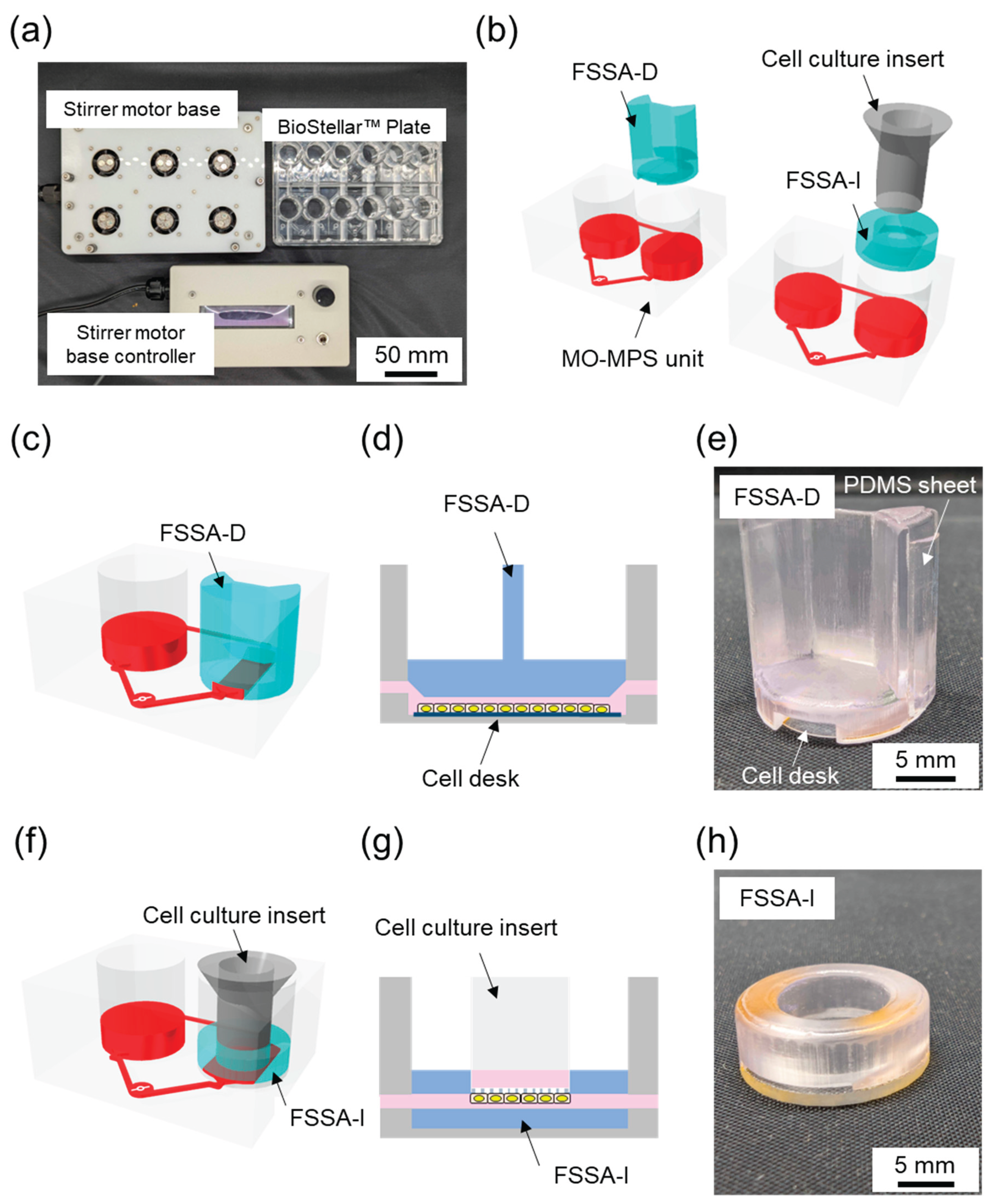
Figure 2.
Flow simulation and experimental validation of the cell culture chamber in BioStellar™ Plate and fluid shear stress attachments (FSSAs). (a) Illustrations of the simulated cell culture chamber and mounted FSSAs, indicating inlet/outlet (blue) and analysis regions (pink): the bottom surface of the cell culture chamber for the BioStellar™ Plate, the channel floor for FSSA-D, and the flow region underneath the insert membrane for FSSA-I. (b) Simulated fluidic shear stress distributions at 100 µL/min in the XY-plane: the cell culture chamber exhibits low fluidic shear stress throughout the culture area, whereas the FSSA-D channel produces a stable, uniform shear profile, and the FSSA-I channel generates basal-directed laminar flow along the underneath of the insert membrane. (c) Comparison of simulated and experimentally measured shear stress for FSSA-D across various flow rates. (d) Comparison of simulated and experimentally measured shear stress for FSSA-I across various flow rates.
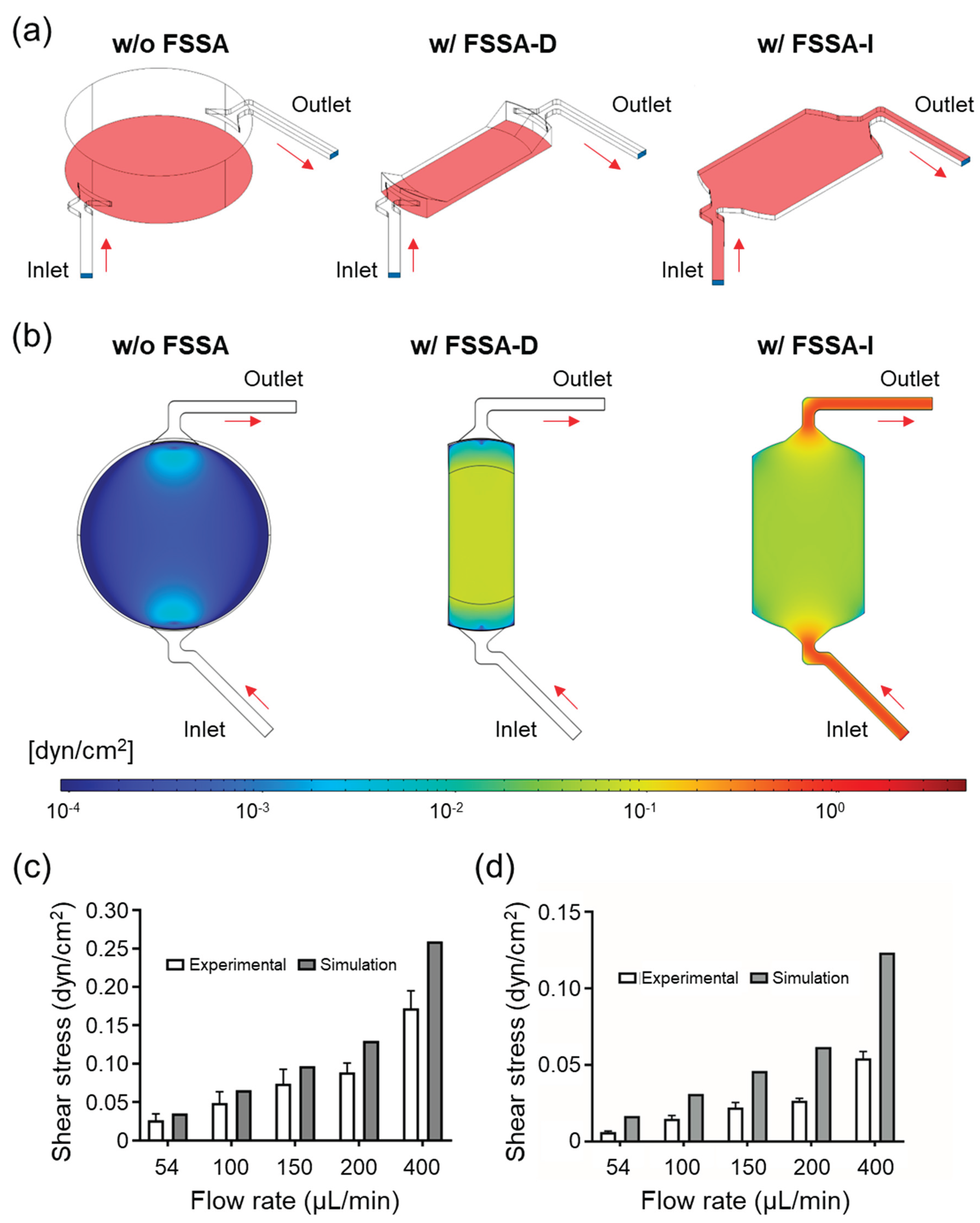
Figure 3.
Caco-2 cells cultured under static and fluidic shear stress (FSS) conditions using FSSA-D. (a) Representative fluorescence images after 5 days of culture, stained for nuclei (DAPI, blue), F-actin (Phalloidin, green), and tight junctions (ZO-1, red). (b) Confocal cross-sectional images showing epithelial thickness under static and FSS conditions. (c) Quantitative comparison of epithelial thickness between static and FSS conditions. Data are presented as mean ± SD; ***P < 0.005.
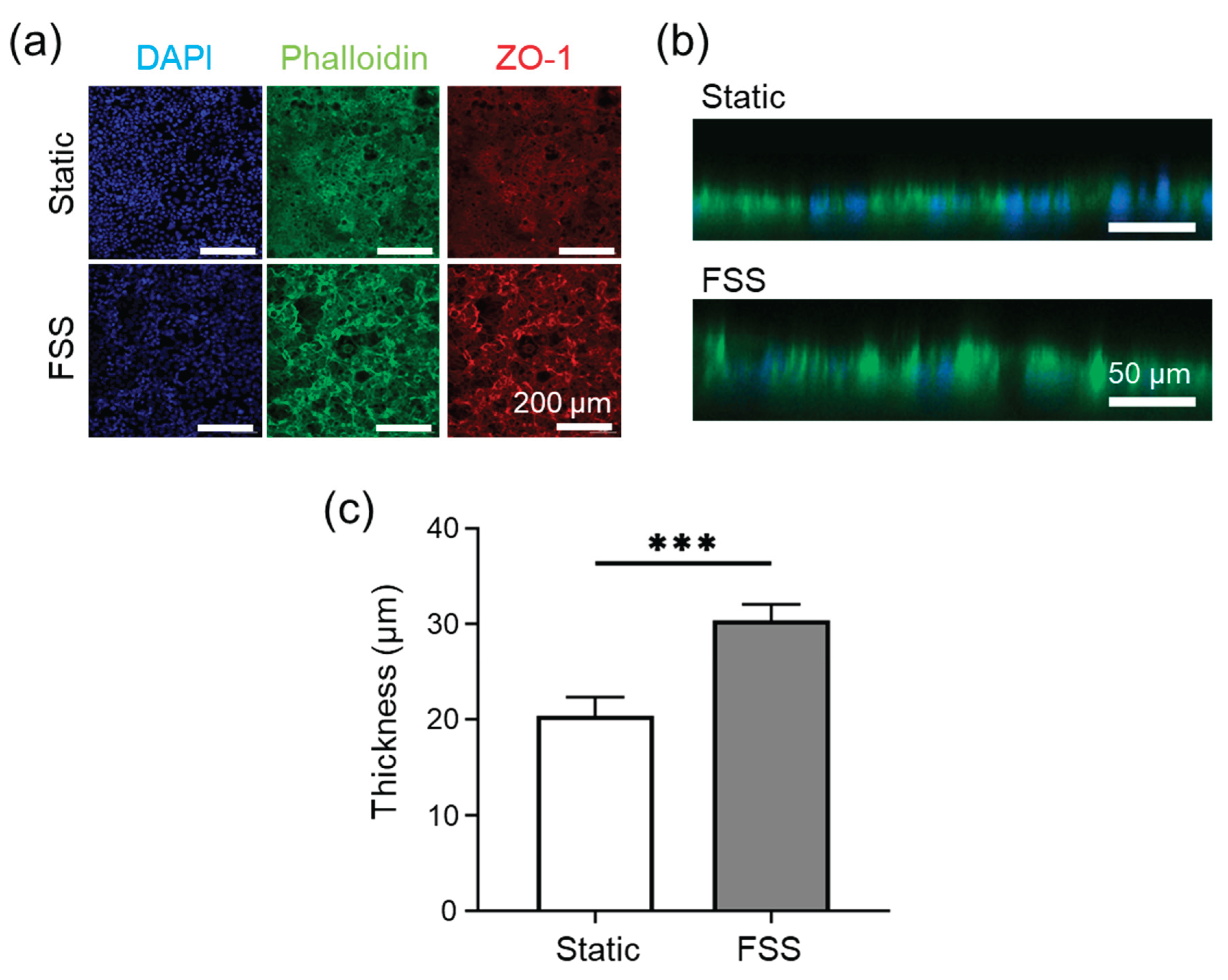
Figure 4.
Caco-2 cells cultured under static and fluidic shear stress (FSS) conditions using FSSA-I. (a) Representative fluorescence images after 10 days of culture, stained for nuclei (DAPI, blue), F-actin (Phalloidin, green), and tight junctions (ZO-1, red). (b) Representative confocal z-stack images showing cross-sectional views of epithelial thickness. (c) Quantitative comparison of epithelial thickness between static and FSS conditions. (d) TEER measurements during 10 days of culture under static and FSS conditions. Data are presented as mean ± SD; *P < 0.05, **P < 0.01.
Disclaimer/Publisher’s Note: The statements, opinions and data contained in all publications are solely those of the individual author(s) and contributor(s) and not of MDPI and/or the editor(s). MDPI and/or the editor(s) disclaim responsibility for any injury to people or property resulting from any ideas, methods, instructions or products referred to in the content. |
© 2025 by the authors. Licensee MDPI, Basel, Switzerland. This article is an open access article distributed under the terms and conditions of the Creative Commons Attribution (CC BY) license (http://creativecommons.org/licenses/by/4.0/).
Copyright: This open access article is published under a Creative Commons CC BY 4.0 license, which permit the free download, distribution, and reuse, provided that the author and preprint are cited in any reuse.


