
Submitted:
04 August 2025
Posted:
05 August 2025
You are already at the latest version
Abstract
Understanding the complex fiber architecture of the heart is critical for modeling its electrical and mechanical behavior. Traditional methods such as dissection are invasive, time-consuming, and prone to error. Diffusion Tensor Imaging (DTI) provides a non-invasive alternative to map the anisotropic fiber structure of the myocardium. However, DTI data often suffer from noise and misaligned vectors, particularly at boundaries between excitable and non-excitable tissues. This work proposes a novel filter—Weighted Effective Sphere (WES)—that effectively corrects and smooths misaligned vectors without significantly altering neighboring fiber directions. A refined version, Moving Weighted Effective Sphere (MWES), is also introduced for enhanced spatial reconstruction and visualization of heart fibers. The proposed algorithms outperform traditional filters in preserving anatomical fidelity, reducing noise, and enabling realistic rescaling of DTI datasets, thereby improving the accuracy of cardiac simulations.
Keywords:
Myocardium fibers
; cardiac modeling
; WES filter
; MWES
; heart fiber structure
1. Introduction
The muscular structure of the heart is responsible for pumping the blood and also the electrical conduction propagation inside the heart [1]. It can be seen as groups of fibers that are wound together in a special arrangement that make the heart operate in an optimal fashion [2]. Previously, information about fiber structure was obtained by means of dissections where the heart is sliced layer by layer and then the orientations of the fibers on each layer are measured manually [3,4,5]. The dissection method is very time consuming and subject to errors. Recently, this information has been obtained using advanced radiology methods such as Diffusion Tensor MR imaging (DTI) [6,7]. One of the most remarkable features in fibers arrangement is that they change their directions gradually and smoothly from Epicardium to Endocardium [3,4,5,8,9].
The Myocardium fibers (myofibers) are composed of cardiac cells [10,11,12,13] (Figure 1). The cardiac cells are almost branched cylindrical in shape (length: 50-100 μm, diameter: 10-20 μm [11,14,15]) and the connection between two cells in the same myofibers is achieved by intercalated disc which contains gap junctions that permits high ions exchange from cell to cell. Much of the membrane surface is made of an electrically insulating material which permits the ions exchange with the external medium of the cell through some channels across the membrane.
The cell’s cytoplasm consists of glycogen [10,11,12,13], and there is one or occasionally two nuclei in the center. It contains myofibril and other organelles. The glycogen is a fluid produced from glucose and acts as the working medium for all biological activities in the cell. The myofibril consists of cylindrical organelle found in all muscular cells. It is responsible for cell contraction and it is extends the length of a muscular cell, and consists of two types of filaments, namely the actin (thin protein filament) and the myosin (thick protein filament) [10,11,12,13,14,16]. The filaments are organized into repeated subunits called sarcomeres along the length of the myofibril in the longitudinal direction of the cardiac cell. The cardiac cell is contracted as sarcomeres filaments slide over each other.
The heart wall is divided into three layers (Figure 2) namely the Epicardium, the Myocardium, and the Endocardium [10,11,12,13,15,16]. The Epicardium is the external shell of the heart that is surrounded by the pericardium wall. The space between these walls contains a fluid (pericardium fluid) that reduces the friction between them while the heart is beating. The Epicardium wall covers the surface of the heart and forms a protective layer for the Myocardium wall. Epicardium cells in general are very thin and contain a relatively low amount of cytoplasm and their extracellular fluid content is relatively low as the cells are close to one another. Also, there are no blood vessels crossing their tissues where the required materials are supplied to their extracellular fluid indirectly from the neighbor cells [10]. The Endocardium wall forms the deepest layer in the heart wall. It is composed of cells which are much like the Epicardium cells [10]. It covers the surface of the trabecular muscles of the Myocardium and forms a surface that is smooth enough to allow blood to flow without turbulence, which would damage the chamber walls.
In general, there are some fat tissues around the Epicardium wall, especially, in the regions that surround arteries [10] as shown in Figure 2, which can be removed using Diffusion Volume scalar index [19]. The Myocardium wall contracts due to the effect of electrical stimulation that is initiated using the conduction network of the heart. This conduction network can be extracted from the DTI scan with different ways [20,21] and then can be used to model the excitation propagation in the Myocardium based on Reaction Diffusion Equation (RDE) [22].
Having the heart modeled as a fiber structure will leads to more realistic in modeling its electrical excitation than finite element model and can be used in modeling its mechanical action as well; however, it will also cost much processing time. Rescaling the heart to a smaller resolution can help in improving the processing time, but using regular filters during the rescale process will significantly affect fibers structure. This research focus on developing a new filter that works with such a case.
2. Methods
2.1. DTI Images
Diffusion Tensor MRI (DTI) is an MRI modality that able to model the anisotropic structure of the scanned tissue which makes it suitable for modeling the heart fibers structure. DTI is capable of describing the diffusion tensor of a sample in terms of three eigenvalues (diffusion coefficients) in the direction of three eigenvectors depending on the six images that are produced by the DTI scanner [17]. This model considers the first eigenvector to be in the principal direction of diffusion and has the largest diffusion coefficient. As the largest amount of water will be in the longitudinal direction of cells, then the principle direction of diffusion, which has the largest diffusion coefficient, will be locally tangential to the fibers direction. This indicates that the amount of water molecules in a certain direction is directly related to the diffusion coefficient.
2.2. Modeling of the Heart from DTI
The DTI data that contains the Myocardium will contain some acquisition noise, and some misaligned vectors, which need to be filtered out because they will affect the excitation propagation especially if these zones are non-excitable materials like small vessels that cross the Myocardium. These errors arise because of the macroscopic scale of the DTI, and also because the DTI scanner cannot differentiate between excitable and non-excitable tissues. For example, in the case of the contact locations of Myocardium-wall and Epicardium-wall, the main diffusion direction of the two structures does not necessary have to be the same, so on the macroscopic scale the vectors representing that space will not be the real direction of Myocardium at this location. Using regular filters to correct the direction of the out-of-order vectors lead to made large modification to the Myocardium data. Then it is required to design a special filter that can detect misaligned vectors and correct their directions without affecting neighbor vectors. After correcting misaligned vectors, a smoothing filter may be applied to enhance fibers directions.
2.3. The Weight Effective Sphere (WES) Filter
A new filtering algorithm is proposed for correcting and smoothing DTI data, which is to be called the Weighted Effective Sphere (WES) algorithm. This new algorithm depends on the fact that fibers change their direction smoothly from location to the neighbor locations. Then if a vector suddenly changes its direction with a large amount, it can be considered a misaligned vector. The aim is to consider all elements that surround the current element in the space included inside a sphere of radius R and current element as the center of that sphere. By giving equal weights (unity) to all elements, and finding their mean and standard deviation (excluding current element), elements that have directions lay inside the range Mean ± SD (68%) are considered Effective Elements. If the current element direction is out of this range, then it is considered as a misaligned vector and its direction will be corrected to the mean of the effective elements only. A more general formula can be identified by multiplying the standard deviation with a scaling factor C where C is a positive real number. The steps in the algorithm are as follows
- 1-
- Take the Mean value of all fiber directions included in a sphere of radius R and current element as the sphere center (excluding current fiber).
- 2-
- Derive the SD for all fibers inside the sphere.
- 3-
- If the current fiber direction is out the zone of the Effective Elements (Mean ± C*SD), then it is considered an out of order fiber and its direction is readjusted to the Mean direction of the Effective Elements only.
- 4-
- Store the direction in a new map.
The value of C is selected according to the relation between the number of updated elements and value of C for the entire space (Figure 3). Large values of C will reduce the sensitivity of the filter since the range Mean ± C*SD will be large enough to include most of current fiber directions and lead to correcting little number of vectors, while small values for C will increase the sensitivity of the filter, which will lead to modifying large number of vectors. After several trials, the selected value of C was 1.75.
The WES algorithm can be extended to act as a smoothing filter by updating the previous algorithm. The difference is to include the current fiber in calculations and give different weights to elements where the sphere center has the largest weight and sphere surface has the lowest weight. The steps in the algorithm steps are now as follows
- 1-
- Take the Mean value of all fiber directions included in a sphere or radius R and current fiber as the sphere center.
- 2-
- Derive the SD for all fibers inside the sphere.
- 3-
- Consider fibers of Effective Elements (Mean ± C*SD) and recalculate their Mean by giving a larger weight to the current fiber (which is in the center of the sphere) according to the number of Effective Elements inside the sphere.
- 4-
- Store direction in a new map.
3. Results
This algorithm is applied to the DTI dataset [23] and it was capable of correcting the misaligned vectors as shown in Figure 4, where the these images represent the principle direction of diffusion in a certain slice and the color of each vector indicates the direction of the fiber with respect to long axis of the heart where red tends to the upward, blue tends to the downward, and green indicates horizontal.
This smoothing step has been applied to DTI data, and the result was a more smooth arrangement of vectors without a large modification (Figure 5d). For example, by comparing WES smoothing filter with some other smoothing filters as shown in Figure 3, it can be seen that WES work as a selective filter and affects some vectors only without modifying neighbor vectors. The correlation coefficient (CC) for a sample of fibers vectors are calculated for each filters referring to the original image, and the WES method was found to have the largest coefficient.
The Weighted Effective Sphere can be used also to resize DTI data to other resolutions (Figure 6).
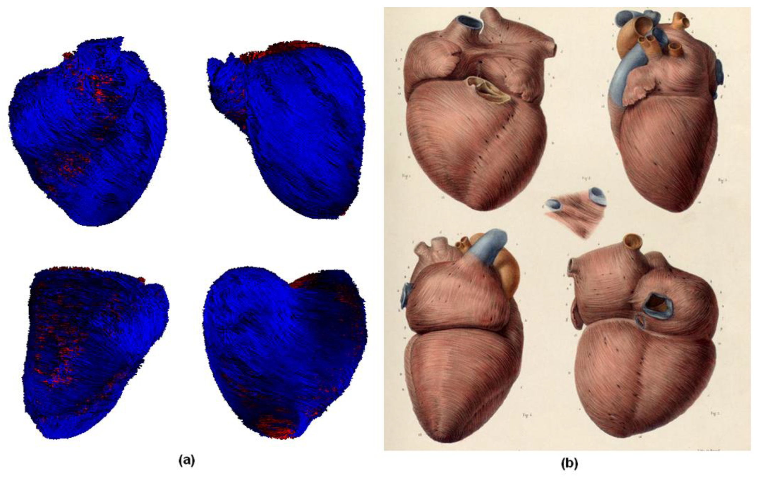
An updated version of Weighted Effective Sphere (smoothing version), which the author called the Moving Weighted Effective Sphere (MWES) method because the center of the sphere is moving in space, was developed to connect and visualize the cardiac structure, and by comparison to anatomical structure of the heart it gives visually similar results (Figure 7).
4. Conclusion
This study introduced the Weighted Effective Sphere (WES) filter as an effective method to correct and smooth the fiber directions extracted from cardiac DTI datasets. Unlike conventional filters, WES adaptively detects and corrects misaligned vectors using statistical criteria within a spherical neighborhood, preserving local structure and avoiding over-smoothing. Additionally, the smoothing version of the filter demonstrated the ability to enhance fiber continuity while maintaining anatomical accuracy. An extended version, MWES, was developed for visualizing the heart’s fiber architecture, achieving results visually consistent with actual anatomical structures. The method also proved efficient in rescaling DTI volumes, making it a promising tool for realistic cardiac modeling and simulation. Future work will focus on integrating WES/MWES into large-scale cardiac electrophysiology and mechanical models to further validate their clinical applicability.
Acknowledgments
Dr. Patrick A. Helm and Dr. Raimond L. Winslow at the Centre for Cardiovascular Bioinformatics and Modelling of John Hopkins University and Dr. Elliot McVeigh at the National Institute of Health for provision of DTI data.
References
- A.C. Guyton "Human Physiology and Mechanisms of Diseases" 5th Ed., Saunders Co., (1992), ISBN: 0-7216-3961-5.
- M.J. Kocica, A.F. Corno, F. Carreras-Costa, M. Ballester-Rodes, M.C. Moghbel, C.N.C. Cueva, V. Lackovic, V.I. Kanjuh, F. Torrent-Guasp "The helical ventricular myocardial band: global, three-dimensional, functional architecture of the ventricular myocardium" Euro. J. Cardio-thoracic Surg., (2006); 29S: S21—S40.
- D.D. Streeter, H.M. Spotnitz, D.P. Patel, J. Ross and E.H. Sonnenblick "Fibre orientation in the canine left ventricle during diastole and systole". Circ Res., (1969); 24(3): 339-347.
- F.P. Mall "On The Muscular Architecture of the Ventricles of the Human Heart" The American Journal of Anatomy (1911); vol. 11(3):211-266.
- R.F. Shaner "On the Mascular Architecture of the Ventricles of the Alligator Heart, with a note on the Formation of the Interventricular Septum of Birds and Mammals" The Ana. Rec. J., (1924); 29(1):21-32.
- J.M. Peyrat, M. Sermesant, X. Pennec, H. Delingette, C. Xu, E. McVeigh and N. Ayache "Statistical Comparison of Cardiac Fibre Architectures", FIMH (2007); 4466: 413-423.
- L. Zhukov, A.H. Barr "Heart-Muscle Fibre Reconstruction from Diffusion Tensor MRI" VIS 2003. IEEE, (2003); Conf. Proc.: 597-602.
- M. McLean and J. Prothero "Determination of Relative Fibre Orientation in Heart Muscle: Methodological Problems", Wiley InterScience Journal (1992); 232(4): 459-465.
- F. Torrent-Guasp, M.J. Kocica, A.F. Corno, M. Komeda, F. Carreras-Costa, A. Flotats, J. Cosin-Aguillar and H. Wen "Towards new understanding of the heart structure and function", European Journal of Cardio-thoracic Surgery (2005); 27:191–201. [CrossRef]
- B. Pansky "Dynamic Anatomy and Physiology", Macmillan Pub. co. (1975), ISBN: 0-02-390740-1.
- J.W. Hurst, R.B. Logue, R.C. Schlant and N.K.Wenger "The Heart", 3rd Ed., Mc Graw-Hill (1974), ISBN: 0-07-031471-3.
- J. Clancy and A.J. Mc Vicar "Physiology and Anatomy: A Homeostatic Approach", 2nd Ed., Arnold (2002), ISBN: 0-340-76237-X.
- P.R. Wheater, H.G. Burkitt and V.G. Daniels "Functional Histology: A Text and ColourAtlas" 2nd Ed., Longman Group UK Ltd., (1987), ISBN: 0-443-02341-7.
- G.J. Tortora and B. Derrickson "Principles of Anatomy and Physiology", 11th Ed., John Wiley & Sons, Inc. (2006), ISBN: 0-471-68934-3.
- R.G. Kessel "Basic Medical Histology: The Biology of Cells, Tissues, and Organs", Oxford University Press, Inc. (1998), ISBN: 0-19-509528-6.
- C. Brooker "Human Structure and Function", 2nd Ed., Mosby Int. Ltd. (1998), ISBN: 0-7234-2661-9.
- S. Standrint, H. Ellis, J.C. Healy, D. Johnson, A. Williams, P. Collins and C. Wigley "Gray's Anatomy",39th Ed., Elsevier (2005), ISBN: 044-07168-3.
- E.P. Widmaier, H. Raff and K.T.Strang "Vander's Human Physiology: The mechanisms of Body Function", 10th ED., Mc Graw Hill (2006), ISBN: 0072827416.
- Elaff, I. “Modeling of the Human Heart in 3D Using DTI Images”, World Journal of Advanced Engineering Technology and Sciences, 2025, 15(02), 2450-2459. [CrossRef]
- El-Aff, I.A.I. "Extraction of human heart conduction network from diffusion tensor MRI" The 7th IASTED International Conference on Biomedical Engineering, 217-22.
- Elaff, I. “Modeling the Human Heart Conduction Network in 3D using DTI Images”, World Journal of Advanced Engineering Technology and Sciences, 2025, 15(02), 2565–2575. [CrossRef]
- Elaff, I. “Modeling of The Excitation Propagation of The Human Heart”, World Journal of Biology Pharmacy and Health Sciences, 2025, 22(02): 512–519. [CrossRef]
- The Center for Cardiovascular Bioinformatics and Modeling, John Hopkins University Site "http://www.ccbm.jhu.edu/research/DTMRIDS.php".
- U.S. National Library of Medicine “http://www.nlm.nih.gov/”.
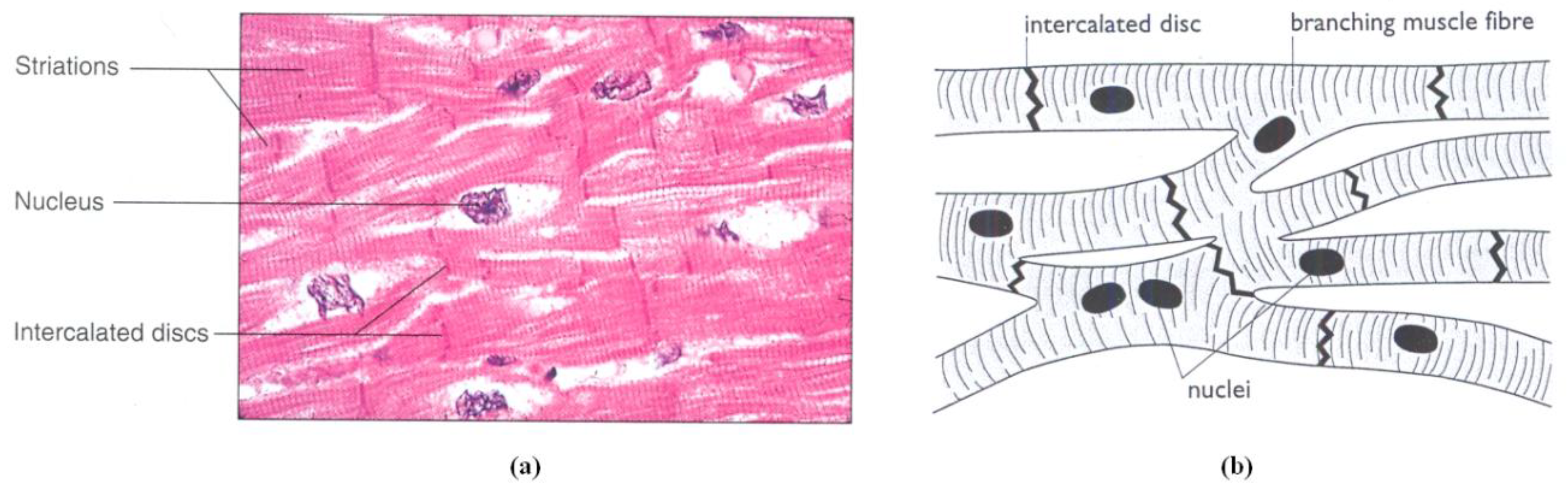
Figure 2.
The heart wall [16].
Figure 2.
The heart wall [16].
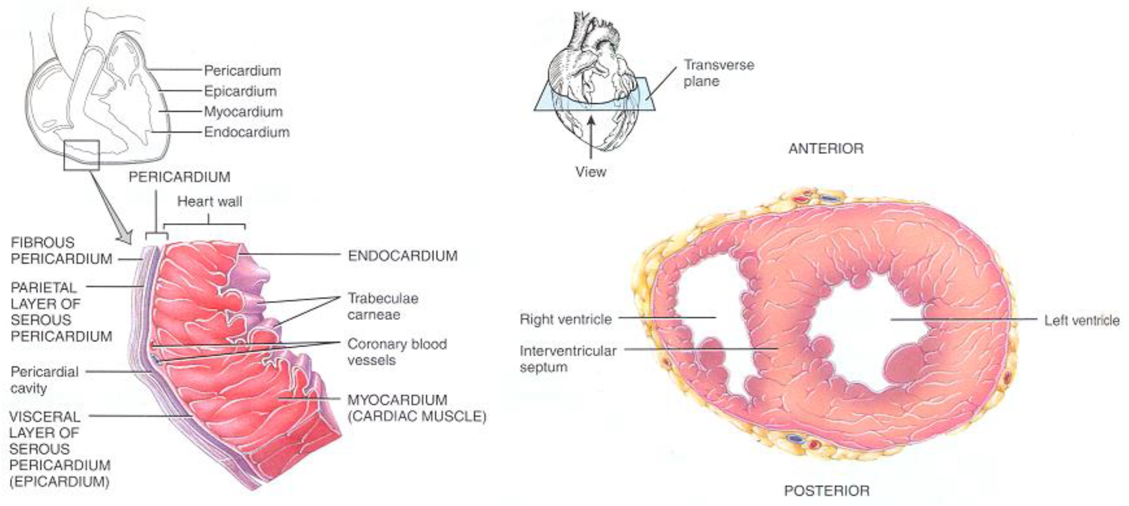
Figure 3.
Relationship between Sphere radius R, weighting factor C and number of updated elements in the original DTI.
Figure 3.
Relationship between Sphere radius R, weighting factor C and number of updated elements in the original DTI.
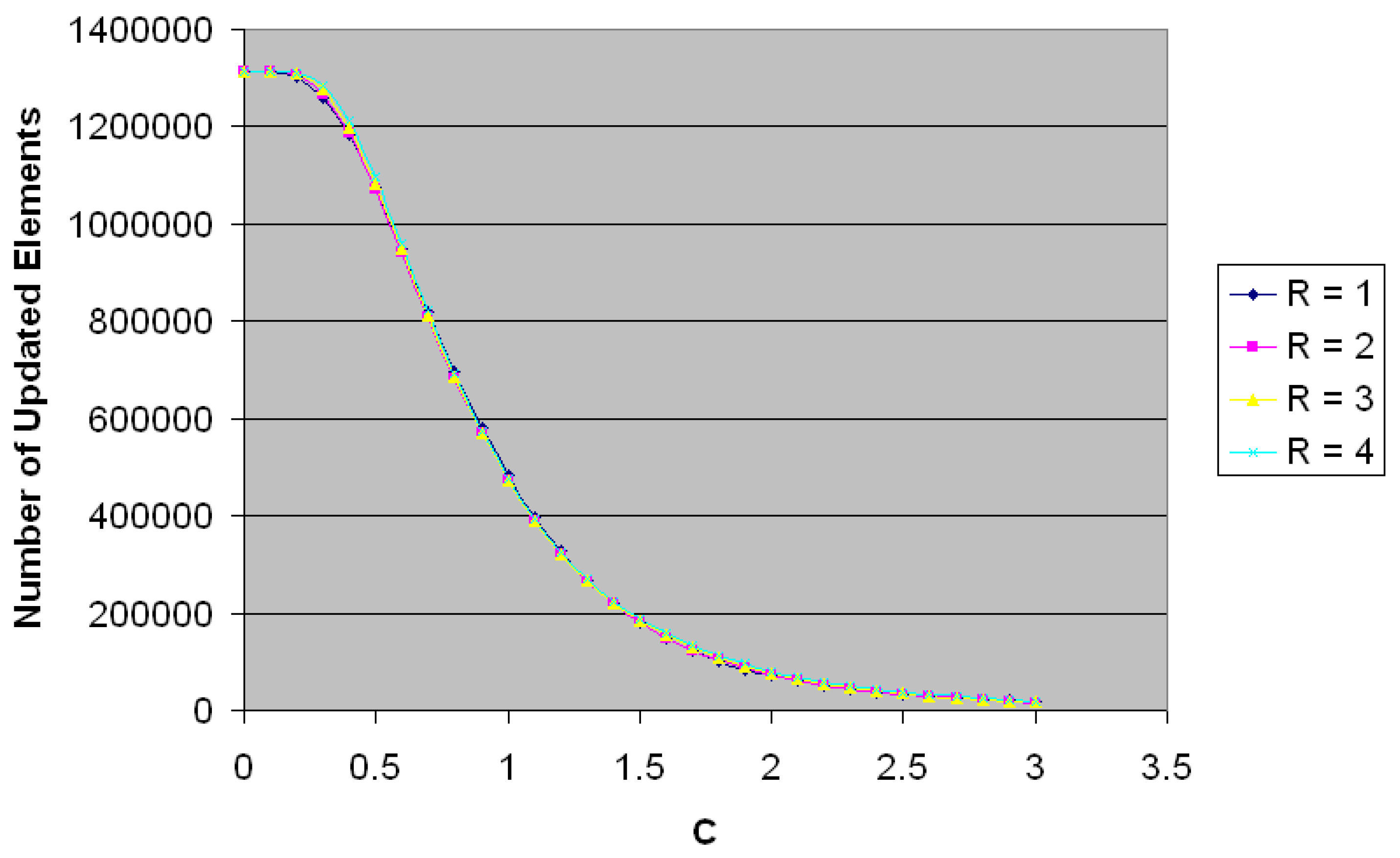
Figure 4.
Noise Removal using WES: Original DTI slice (a) Filtered slice (b).
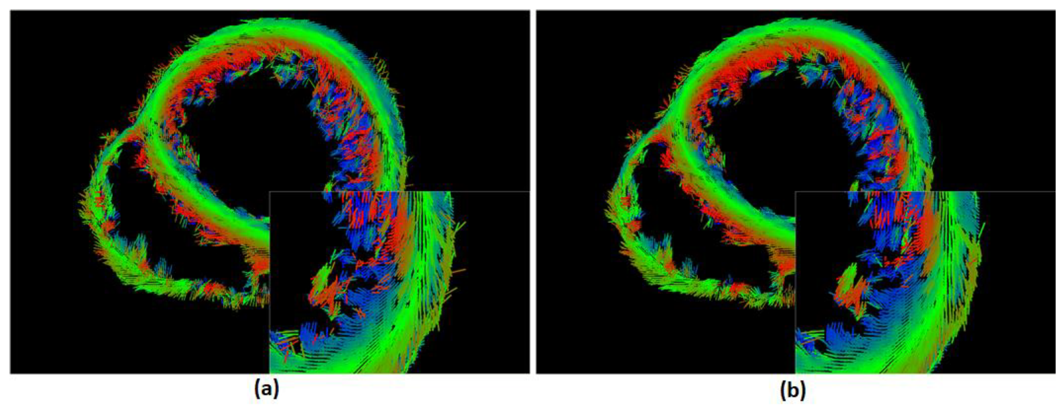
Figure 5.
Use of WES to filter the original slice (a), Filtering using Median filter (b), Filtering with Gaussian filter (c), and filtering using WES (d).
Figure 5.
Use of WES to filter the original slice (a), Filtering using Median filter (b), Filtering with Gaussian filter (c), and filtering using WES (d).

Figure 6.
(a) Original DTI slice 256x256x110, (b) Resize using WES from 256x256x110 to 110x110x110, (c) Resize using WES from 256x256x110 to 55x55x55.
Figure 6.
(a) Original DTI slice 256x256x110, (b) Resize using WES from 256x256x110 to 110x110x110, (c) Resize using WES from 256x256x110 to 55x55x55.
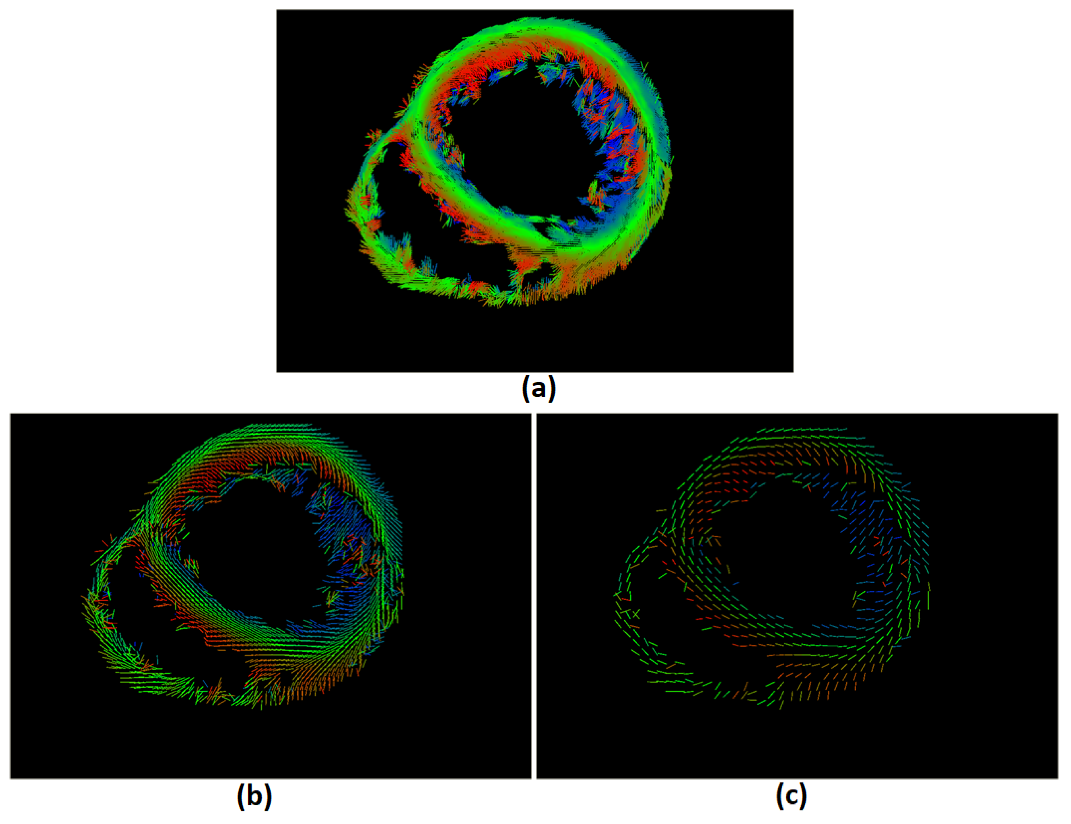
Figure 7.
(a) Visualization of the heart’s fibers using MWES from different views compared to (b) real heart fibers images [24].
Figure 7.
(a) Visualization of the heart’s fibers using MWES from different views compared to (b) real heart fibers images [24].
Disclaimer/Publisher’s Note: The statements, opinions and data contained in all publications are solely those of the individual author(s) and contributor(s) and not of MDPI and/or the editor(s). MDPI and/or the editor(s) disclaim responsibility for any injury to people or property resulting from any ideas, methods, instructions or products referred to in the content. |
© 2025 by the authors. Licensee MDPI, Basel, Switzerland. This article is an open access article distributed under the terms and conditions of the Creative Commons Attribution (CC BY) license (http://creativecommons.org/licenses/by/4.0/).
Copyright: This open access article is published under a Creative Commons CC BY 4.0 license, which permit the free download, distribution, and reuse, provided that the author and preprint are cited in any reuse.


