
Submitted:
01 August 2025
Posted:
04 August 2025
You are already at the latest version
Abstract
The first permanent magnet electric machines appeared in the first half of the last century and their evolution was continuous as magnets with high magnetic energies appeared and magnetic circuits were created that allowed for efficient use of the magnets. The solution of the asynchronous motor with two stators with a massive rotor described in previous work opened the way to a synchronous variant of the machine with two stators, using rare earth permanent magnets, which are arranged on both cylindrical surfaces of the rotor. In this way, the volume of the magnets and the flux of the machine can be increased. The rotor construction made of solid steel, mechanically robust, does not disturb from an electromagnetic point of view, because it rotates synchronously with the fundamental of the stator field, so it will no longer induce eddy currents in the rotor iron in a permanent regime. In the synchronous variant, part of the inductor flux is closed through the rotor, which can be an advantage for the optimal use of the active surfaces of the machine.
Keywords:
NdFeB permanent magnets
; double stator
; electromagnetic performance
; double active surfaces
1. Introduction
The greatest developments in the field of permanent magnet integration have been achieved in the last 20 years, with the intensive use of rare earth magnets, especially after the discovery of the NdFeB alloy [1,2,3,4,5], which has the highest magnetic energy.
In the field of synchronous machines, permanent magnets have been used to replace electromagnetic excitation. The advantages that arise from this are the following: simplification of construction by eliminating excitation windings, the absence of any sliding contacts, greater operational reliability, reduced overall dimensions and higher efficiency due to the elimination of excitation losses [6,7,8,9,10].
If in the construction of generators the use of magnets is limited, due to the impossibility of regulating the excitation flux, synchronous motors with permanent magnets are widely used, in numerous constructive variants. By properly calculating the magnetic circuit, it is possible to operate at unit or even capacitive power factor, a fact unachievable in another type of motor [11]. The lack of sliding contacts, therefore of sparks, recommends these motors in drives intended to work in explosive environments. Powered by static frequency converters, synchronous motors with permanent magnets are used in applications where good speed regulation within wide limits is required [12,13,14,15]. A decisive advantage is the property of these motors to maintain their speed unchanged during network voltage disturbances.
The discovery of the NdFeB alloy, due to its high magnetic energy, places permanent magnet synchronous motors at the top of the hierarchy in terms of energy parameters and torque/mass ratio, but the currently quite high price of these magnets makes their use limited in the medium and low power range.
Below are some examples of permanent magnet synchronous motor (PMSM) constructions with radial air gap.
The stator of these motors is structurally identical to that of induction motors, being made of electrical steel sheets, with notches in which the stator winding is distributed. Figure 1 shows the general construction of a radial air gap MSPM.
There is a wide variety of constructive solutions for the cylindrical rotor, some of which are presented below.
The cylindrical rotor of these machines can be made in normal construction (Figure 2a) or with salient poles and squirrel cage into a common construction (Figure 2b).
Figure 3a shows a constructive solution that uses permanent magnets, placed radially and circularly to increase the magnet surface area per pole and achieve the greatest possible concentration of the induction field.
The constructive solution presented in Figure 3b, with the magnets arranged in a zig-zag pattern, achieves the highest concentration ratio (the ratio between the active magnet surface area and the surface area of a pole) for a four-pole construction, but has the disadvantage of a relatively high rotor leakage coefficient.
Figure 4a and Figure 4b show two rotor designs derived from variable reluctance motor rotors with flux barriers, where permanent magnets were introduced instead of the barriers.
It is observed that the pole area is larger than the magnet area and the magnet height is smaller, which suggests that the solution is only suitable for the use of rare earth magnets, which, having relatively high remanent inductions and coercive field intensities, are suitable for relatively small magnet areas and heights, as can be seen from the figure.
Another constructive solution that uses high-energy permanent magnets, based on samarium or neodymium, is the one in Figure 4c, for a four-pole motor.
The constructive solutions shown in Figure 4a, Figure 4b and Figure 4c also have a cage placed radially over the permanent magnets. This cage has a starting role, if the motor is used as a synchronous motor with permanent magnets powered by the 50 Hz network, operating at constant speed [16,17,18,19].
In the case of motors intended to operate in variable speed drive systems, systems that also control the internal angle, the presence of the cage for starting is no longer necessary. If permanent magnets with a high coercive magnetic field intensity value are used in these motors, such as those based on samarium or neodymium, then the presence of the cage is no longer necessary for its shielding role and can be dispensed with.
AC motors with double stators or rotors and permanent magnets are known in the literature, but their construction is quite complicated and they are generally made for use in the field of electric vehicles. [20,21,22].
In the paper [23] presented by Aymen Flah et al. it is shown that the use of AC motors for EVs allows the creation of advanced circuit topologies to suit machines with two rotors or two stators. In the paper, two control configurations of electric machines for EVs are presented and their advantages and disadvantages are discussed, and the corresponding mathematical models were developed to improve a Field-Oriented Control (FOC) strategy.
Jiacheng Wu et al. in [24] conduct a comparative study between the single-stator permanent magnet synchronous motor (SS-PMSM) and the double-stator permanent magnet synchronous motor (DS-PMSM), which can make maximum use of the space in the motor cavity to have a higher torque density, thus being more suitable for direct drive situations with low speed and high torque.
In [25] Kwang-Il Jeong et al. present a new double-gap surface-mounted permanent magnet synchronous motor (DAG-SPMSM) and investigate its electromagnetic characteristics. The motor consists of two stators (inner and outer) and a single rotor with permanent magnets on both sides (inner and outer). The magnets are arranged in a zig-zag configuration to isolate the inner and outer magnets of the stator and rotor.
Minchen Zhu et al. consider in [26] that the double stator permanent magnet machine (DSPM) has been shown to have high space utilization and redundant structure, which can be beneficial for improving fault tolerance and torque density performance. In the paper, three configurations of double stator machines are proposed and compared, for which two sets of armature windings are wound in both stators, inner and outer, producing a higher torque component compared to single stator PM machines.
In the study presented in [27] Zhitong Ran et al. compare the electromagnetic performance of radial flux, double rotor, permanent magnet machines (DRPM) with series (S) and parallel (P) magnetic circuits for two rotors, i.e. SDRPM and PDRPM, considering different combinations of slot/pole numbers, stator winding configurations and machine dimensions. The machines are optimized using finite element analysis (FEA) based on genetic algorithms.
The object of the study presented in this paper is the validation of a new structure of an alternating current machine in the synchronous version, characterized by a double stator and a single rotor with radial air gap. The rotor has high specific energy permanent magnets of the NdFeB type glued on both surfaces.
Initially, in a previous work published in Energies [28], we dealt with the asynchronous variant, for which, between the two stators with series-connected windings, a rotor consisting of a cage made of copper bars or cast aluminum rotates. The active surface of a classical asynchronous machine is made up of the notches-gap-bars area, the armature yokes serving to close the flux. In the new structure, the reunion of two active areas of different diameters in a single construction was considered. This machine could be equivalent to two elementary machines coupled on the same shaft if the dimensions of the active areas and their operation were not affected by the reunion.
The flanged construction of the rotor, along with its reduced radial thickness, ensures reduced inertia. However, its mechanical construction must be very carefully studied to ensure perfect concentricity. Finally, given that the flux in the machine is dictated by the total cross-sectional area of the teeth in the inner stator, it can be stated that the asynchronous motor with two stators develops double the torque compared to a standard motor in reverse construction, consisting of the inner stator and the rotor cage.
The synchronous structure we propose in this paper is equivalent to two classical permanent magnet synchronous machines, electrically connected in series and coupled on the same shaft. These elementary machines operate at the same autopilot angle, but their power factors and internal angles differ. Overall, however, the structure with the two stators behaves like a classical permanent magnet synchronous machine.
2. Materials and Methods
Although the solution of the asynchronous motor with two stators and a massive rotor is inefficient compared to a standard motor (the efficiency does not exceed 70% due to the high resistivity of the massive rotor), it paved the way for a synchronous variant of the machine with two stators and a single rotor, using rare-earth permanent magnets, which are arranged on both cylindrical surfaces of the rotor.
In this way, the volume of the magnets and the flux of the machine can be increased.
The rotor construction, by massive steel, mechanically robust, does not pose any problems in terms of electromagnetic aspects, because it rotates synchronously with the component of the fundamental stator field, which no longer induces eddy currents in the rotor iron in a permanent manner.
The stator windings are of the classic type, with a shortened pitch, in two layers. They represent the inductor for the asynchronous version and the induced one for the synchronous version. The number of turns is imposed by the voltage applied to the terminals and by the flux determined by the total section of the inner teeth.
Regarding the connection method of the coils of the two stators, several variants were studied, finally being preferred those in Figure 5.
For the asynchronous version, a series connection of the windings of the two stators and a star connection (Y) of the three phases was adopted. The coils are distributed equally on the two stators, but a distribution different from 50% is also possible (for example 40% in the inner armature and 60% in the outer one) without influencing the machine’s performance decisively.
In the synchronous version, the fluxes are more important, for the same stator construction, and the e.m.f. exceeds 220 V per phase in the case of the connections in Figure 5a.
This is important for operation as a synchronous motor, when the supply voltages cannot exceed this value.
Therefore, for this case, the connection in Figure 5b was chosen, with the parallel connection of the series coil groups of the two stators on each phase. The possibility of parallel connection between the two stators is excluded due to the circulating currents that could appear due to differences between the induced e.m.f.
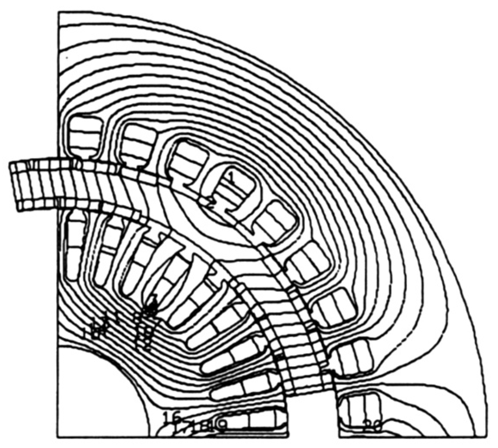
In Figure 6 the lines of the inductor magnetic field, at no-load operation, are represented for the two variants, asynchronous and synchronous
As can be seen, in the synchronous version, part of the inductor flux is closed through the rotor, which can be advantageous for the optimal use of the machine’s active surfaces.
2.1. Technological and Constructive Problems of the Tubular Rotor with Permanent Magnets
2.1.1. Choosing the Type and Number of Magnets
The choice of the type and number of magnets to be fixed on the two bores must take into account:
• Obtaining an e.m.f. as sinusoidal as possible.
• Avoiding saturation of the stator magnetic circuits, so that iron losses remain at acceptable values.
Rare earth magnets capable of providing a value of 0.8 – 0.81 T for the fundamental induction in the air gap were considered.
The radial thickness of these permanent magnets is around 3.5 mm, being made of plates measuring 20 × 15 mm.
With this structure, 6 × 3 magnets per pole are obtained for the outer surface of the rotor and 5 × 3 magnets for the inner surface, representing a pole coverage factor of approximately 2/3 for each rotor surface.
The permanent magnets are fixed to the rotor cylinder by gluing.
At each pole, the six outer magnets are coaxial with the five inner poles.
As can be seen from Figure 7, the outer diameters Φ 224.4 mm and the inner diameter Φ 180 mm must be respected to avoid friction of the rotor against the two stators.
If necessary, the machining of the rotor cylinder can be corrected.
Additionally, the outer magnets can also be fixed with a layer of “polyglass” (glass fibre tape) having a thickness of 0.1 mm.
The construction allows the synchronous machine to be characterized as having sunken poles (smooth rotor). The fluxes that cross the two air gaps are different, part of the field lines closing through the massive rotor.
As can be seen from Figure 6b, part of the flux links both stators, another part only the outer stator.
The construction details of the rotor subassembly are shown in Figure 8a and in the following Figure 8b.
The distribution of the flux depends on the opening (extension) of the permanent magnets on the inside and outside, the width of the teeth of the two stators, the radial thickness of the rotor, and, of course, the saturation of each portion of the magnetic circuit.
2.1.2. Cogging Torque
Due to the high flux and the reduced air gap, permanent magnet synchronous machines exhibit significant tooth torques, their amplitude reaching in some cases up to 30% of the nominal torque.
The periodicity of these torques, which are exerted between the rotor poles and the teeth, is of one tooth pitch, and their shape is asymmetrical in relation to the tooth axis.
Several methods are indicated in the specialized literature for reducing these torques [29,30,31,32], the best known being the inclination of the stator notches with a tooth pitch.
In a two-dimensional calculation (using a calculation program based on the finite element method), the inclination of the notches cannot be taken into account directly, and things become complicated.
The rotor should be rotated discretely, the tooth torques determined at each point, and an average over a tooth pitch calculated using the virtual things method.
During the simulations (with Flux 2D and Flux 3D software, developed by CEDRAT, which are FEM commercial software simulating electromagnetics and thermal physical phenomena), it was found that the determinations are sensitive to the discretization network used during rotor rotation, as well as the connection of nodes at the air gap level.
Thus, for certain networks, the tooth torque was no longer asymmetric.
To solve this problem, for each pair of points placed symmetrically with respect to the tooth axis, the networks were rebuilt until equal and opposite tooth torque values were obtained (differences below 3%).
In the case of the structure studied in this paper, the results are presented in Figure 9, separately for the inner and outer poles in Figure 9a and the resulting tooth torque in Figure 9b.
In a synchronous machine with permanent magnets arranged on the rotor surface, the cogging torque at no-load operation results solely from forces exerted at the pole edges. One tooth is positioned in the middle of the pole and, due to the symmetry of the magnetic field lines at no-load, exerts no tangential force on the rotor. Therefore, the tooth torque depends on the distance between the pole edges, that is, the magnet extension, as well as on the ratio between the width of the tooth and the notch, and on the shape of the induction in the air gap.
A significant reduction in the cogging torque is achieved by setting the opening of the permanent magnet slightly more than an integer multiple of tooth pitches. One solution is to use a rotor consisting of N sectors (in the longitudinal direction) offset from each other by td/N, where td is the tooth pitch. This way, all the harmonics of the tooth torque are cancelled, except for the harmonics that are multiples of N.
Another solution proposes a progressive air gap to make the induction in the air gap as sinusoidal as possible. The sudden, stepwise variation of the induction is completely unfavorable. About the above, the inclination of the notches with a stator tooth pitch, in the opposite direction for the two stators, was provided, a solution easier to achieve for a series production. This solution allows at the same time to improve the e.m.f. curve by reducing the tooth harmonics.
The considerations presented allow the establishment of a transversal geometry presented in Figure 10, for the two variants: asynchronous (a) and synchronous (b).
The idea of the new structure consists in combining two machines with different air gap diameters, each consisting of classical active zones (notches – air gap – bars, for the asynchronous version and notches – air gap – permanent magnets, for the synchronous one) into a single machine, keeping the two active zones and a single pair of yokes for closing the flux.
To the extent that neither the dimensions of the active zones nor the operation of each classical machine are affected by this combination, it can be said, theoretically, that the proposed machine is equivalent to the two simple machines coupled on the same shaft. In practice, however, certain complications arise.
2.2. Numerical Characterization of the Permanent Magnet Synchronous Version of the Double Stator Machine
2.2.1. Generalities
In the synchronous version, the inductor is represented by the rotor with permanent magnets fixed on both sides of a solid steel cylinder, and the induced current is produced by the two stators with connected windings. By grouping the series coils of the two stators in parallel, the e.m.f. of the machine is halved and the current is doubled, which suits the usual voltages of inverters.
It was considered an interchangeability of the two rotors, for asynchronous and synchronous versions, to facilitate experimentation and to make possible a series of comparisons of the results obtained.
The transition from an asynchronous to a synchronous version can be done by replacing the squirrel cage rotor with a permanent magnet rotor and modifying the stator winding connections.
The machine’s characterization was carried out by constructing its vector diagram and calculating its parameters. This calculation can be done by simulations using the finite element method or by analytical methods.
2.2.2. Vector Diagram and Operation Under Load
The permanent magnets are fixed on the cylindrical surfaces of the rotor, and their relative permeability being close to unity (μr = 1.05), the machine can be considered with sunken poles (with a smooth rotor). In the hypothesis of a linear magnetic circuit, the equation of voltages per phase is written:
where R denotes the stator winding resistances, Xσ the leakage reactance, Er the resultant e.m.f. per phase, Xs the synchronous reactance and E0 the no-load e.m.f., the indices “i” and “e” signifying internal and external stators, respectively.
The phase phasor diagram, neglecting the ohmic voltage drops (R << XS), is represented in Figure 11. The no-load operating electromotive voltages of the two stators, E0i and, respectively, E0e, are clearly in phase. Both equation (1) and the phasor diagram viewed from the terminals allow us to see that the machine is equivalent to a classical permanent magnet machine.
It can be considered that the double stator machine is the result of the series connection to the network of two classical machines, which are coupled on the same shaft. If the magnetic circuit of the rotor is not saturated, the two classical machines can be physically separated by a cylindrical cut at the median level of the rotor and studied each one separately.
Through this separation, we will allow the superposition of 4 fluxes existing simultaneously in the machine, 2 inductors produced by the external and internal magnets, respectively, and 2 intrinsic fluxes of each stator winding.
The two elementary machines in which we have sectioned the machine with double stator and magnets fixed on both rotor surfaces operate with the same autopilot angle Ψ, but their power factors and internal angles will be different, because the ratio between the electro motive forces at no-load operation and the synchronous reactances of the two machines is not the same.
2.2.3. Synchronous Reactance of the Machine
The three-phase stator windings, fed with a balanced system of currents, produce a rotating field that induces e.m.f. in their own phases. The voltages are proportional to the currents I that flow through each phase and can be interpreted as an inductive voltage drop XaI at the terminals of a reactance, which is the useful cyclic reactance on phase Xa. The synchronous reactance is the sum of Xa and the leakage reactance on phase Xσ (due mainly to the coil ends).
Figure 12 shows the distribution of the induced reaction flux, in the d-axis, in the absence of the inductor flux.
Because of the very high reluctance of the magnets, the induced reactance is lower than in the electromagnetically excited synchronous machine, in which the air gap reluctance constitutes the predominant term in the total reactance of the circuit.
Therefore, the synchronous reactance of permanent magnet machines is lower and the assumption of neglecting resistances in addition to the synchronous reactances must be made with some caution. In fact, the phase resistance of the stator winding can reach 10% of the synchronous reactance.
2.3. Analytical Model
Analytical models do not require the calculation of the field distribution in the studied structures and allow a flexible, rapid, and sufficiently precise analysis of the influence of various geometric or material parameters on the machine characteristics. Obviously, they suffer from a lack of information about what is happening at local levels.
An analytical model adapted to the proposed construction, with magnets fixed on the rotor surface, reduces the calculation to the active area of the machine, consisting of magnets, air gap and the tooth-notch regions. The yokes are considered to have infinite permeability, but the finite permeability of the stator teeth is taken into account. The permanent magnets are represented by a surface charge density, placed in front of the magnet, according to the Coulombian model. The principle of the model consists in the analytical calculation of the field created by the stator.
The electromagnetic torque results from the interaction between this field and the representative magnetic charges of the permanent magnets. The calculation of the stator field is performed in a simplified geometry, obtained by homogenizing the magnet-air gap region on the one hand and the tooth-notch region on the other hand.
The discrete distribution of the current density in the notches is taken into account. The permeability homogenization of the magnet-gap zone and the tooth-notch zone is performed for an elementary cell equal to one tooth pitch, comprising a stator notch framed by two tooth halves and placed under the rotor magnet.
After homogenization, the rotor becomes smooth.
The calculations are performed under the following simplifying assumptions (in addition to the above):
• Firstly, it is a two-dimensional analysis in which we consider the area of interest to be straight; therefore, the curvature of the bore, as well as end effects, are neglected.
• Secondly, we consider permanent magnets rigid and magnetized in a single direction; their magnetization does not vary in space and remains equal to the remanent one, whatever the demagnetizing fields, if it remains below its critical value Hcr. Each magnet is replaced by superficial magnetic masses, whose density σ at each point on the magnet surface is defined by being the external normal to the magnet surface.
• Thirdly, the field in the air gap has the same amplitude in no-load and load conditions; the stator tooth material then has a fixed permeability, determined by the chosen operating point.
2.4. Thermal Considerations
The existence of the two air gaps as heat barriers by interposing the inner stator instead of the rotor yoke of standard asynchronous motors creates the possibility of producing significant local heating. That is why it seemed necessary to develop an appropriate thermal model for the new proposed structure.
An analogy with an electrical diagram with concentrated parameters was used: the current sources correspond to the power dissipated in various parts in contact; then the electrical voltages correspond to the temperature differences, respectively the heating.
The calculations confirmed the fear that, under conditions of similar current densities, the heating of the inner stator winding exceeds that of the outer winding by about 20°C, which imposed some measures related to the ventilation of the machine.
2.5. Simulation Results for the Two-Stator and One-Tubular-Rotor Permanent Magnet Synchronous Motor
The simulation results of the three-phase permanent magnet synchronous motor with two stators and a single rotor are presented below. The cross-sectional geometry and the discretization mesh, with approximately 46,000 nodes, are also presented.
Figure 13.
Three-phase synchronous motor with two stators and a single rotor, with permanent magnets. (a) Transverse geometry; (b) Discretization network.
Figure 13.
Three-phase synchronous motor with two stators and a single rotor, with permanent magnets. (a) Transverse geometry; (b) Discretization network.
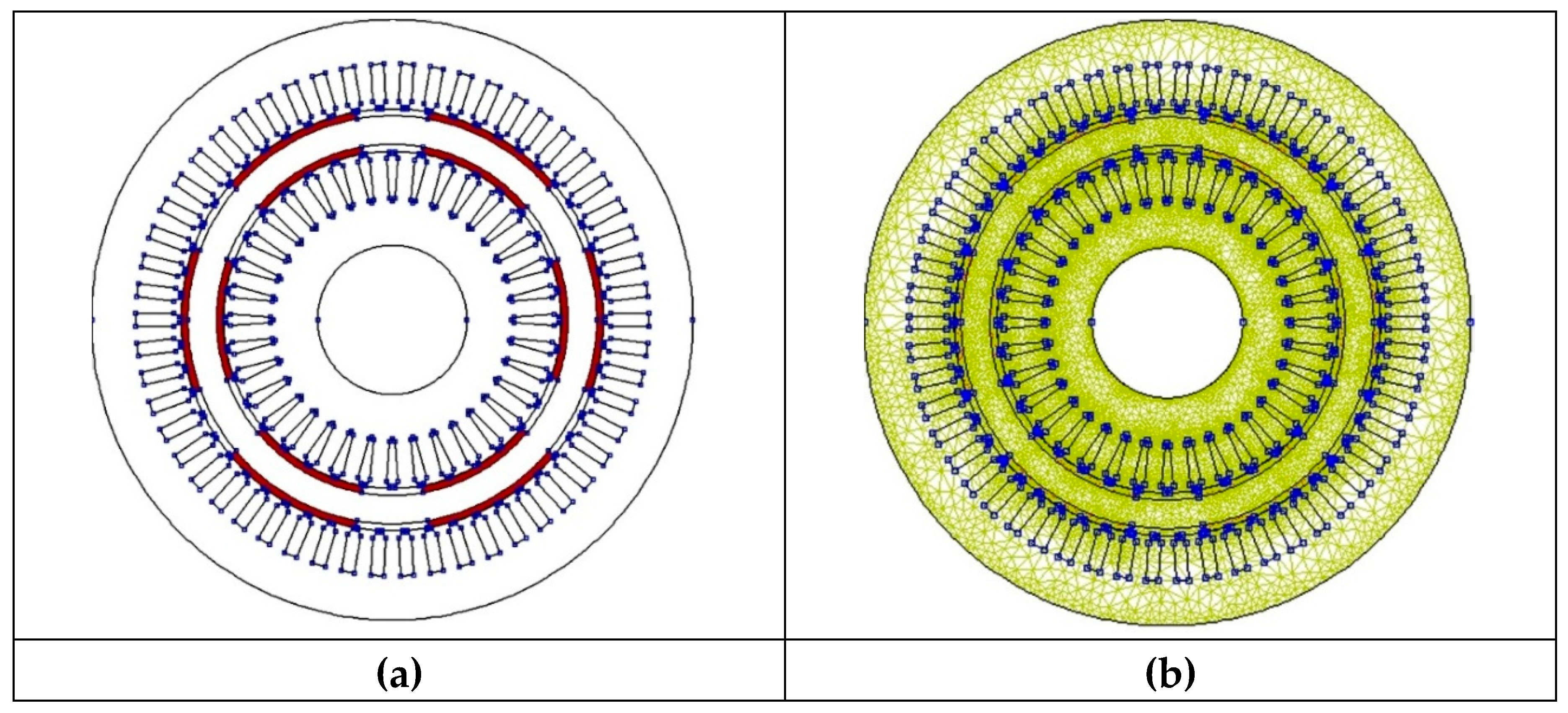
Figure 14.
Three-phase synchronous motor with two stators and a single rotor, with permanent magnets. (a) Magnetic flux paths at no-load operation; (b) Magnetic induction values at no-load operation.
Figure 14.
Three-phase synchronous motor with two stators and a single rotor, with permanent magnets. (a) Magnetic flux paths at no-load operation; (b) Magnetic induction values at no-load operation.
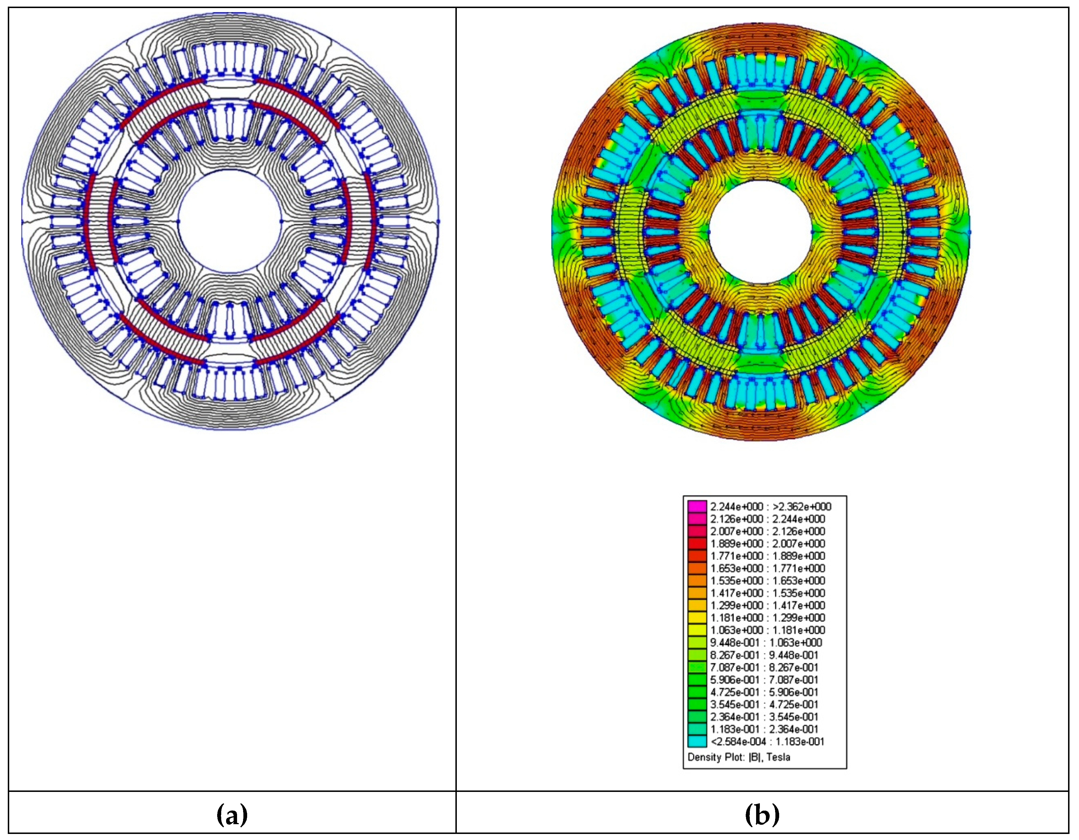
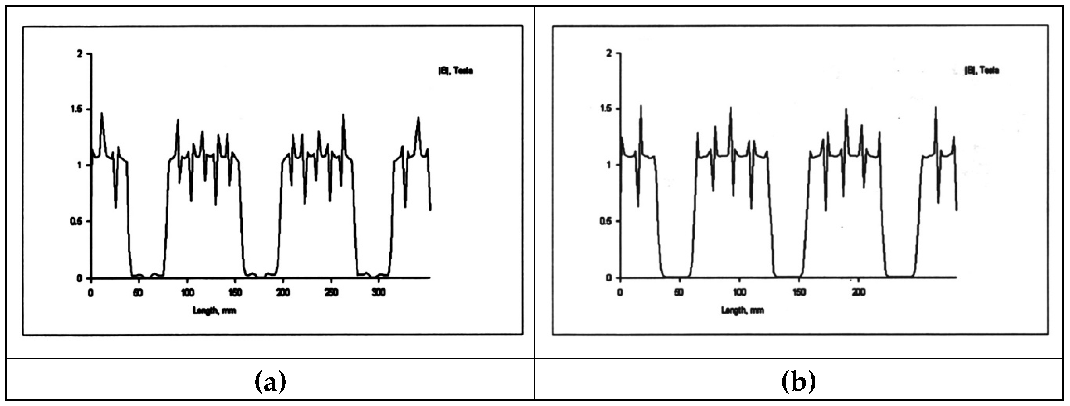
Figure 15.
Three-phase synchronous motor with two stators and a single rotor, with permanent magnets. (a) Magnetic induction in the outer air gap; (b) Magnetic induction in the inner air gap.
Figure 15.
Three-phase synchronous motor with two stators and a single rotor, with permanent magnets. (a) Magnetic induction in the outer air gap; (b) Magnetic induction in the inner air gap.
Thus, previously, we present some of the simulation results for the two-stator tubular-rotor permanent magnet synchronous motor using QuickField™ 6.0 software, which is an efficient finite element analysis package for electromagnetic, thermal, and stress design simulation with a multi-analysis coupled field.
3. Execution and Certification of the Experimental Prototype
3.1. Certification of the Prototype of a Permanent Magnet Synchronous Motor with a Tubular Rotor
After preliminary calculations, and computer simulations, an execution project for the prototype of an asynchronous motor with double stator and tubular rotor in cage were carried out and then the prototype of the motor with double stator and tubular rotor in asynchronous version, with double cage with round bars, was built in collaboration with the prototype workshop at S.C. UMEB S.A., following what was shown in this paper, it emerged that a synchronous version with permanent magnets would be even more efficient than the asynchronous one under the conditions in which, in any case, the stator subassembly remains unchanged.
Consequently, an interchangeable rotor was executed composed of a massive steel tube on which were glued, on both the outer and inner bore, plates of high magnetic energy permanent magnets, produced at S.C. ICPE S.A. (laboratory of Dr. W. Kappel).
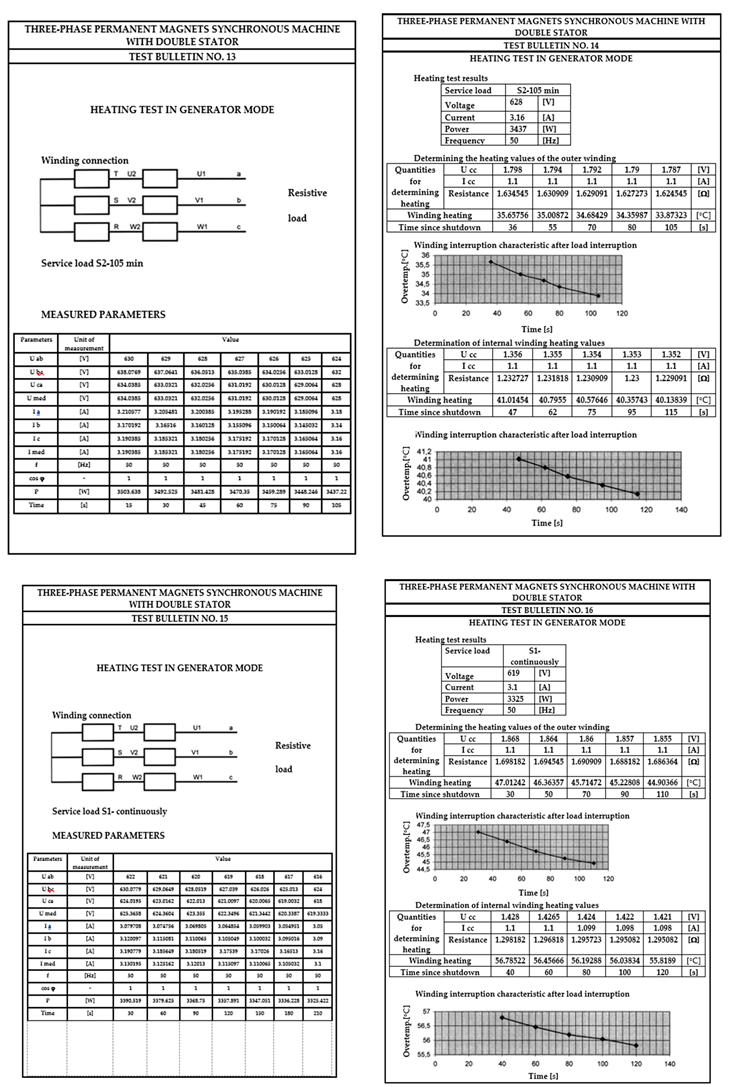
3.2. Carrying Out Tests in the Laboratory of Prototypes from S.C. UMEB S.A. and Test Reports with Experimental Results
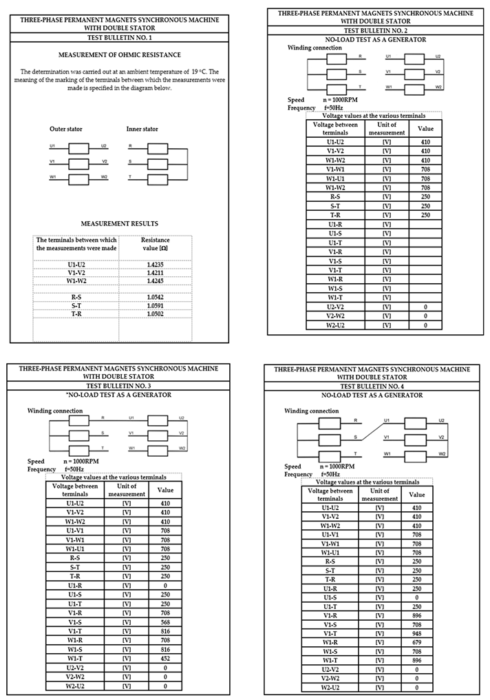
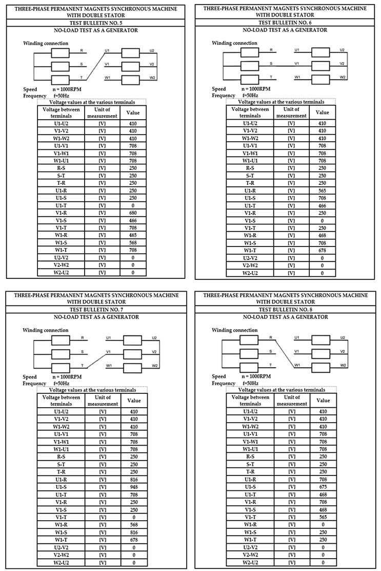
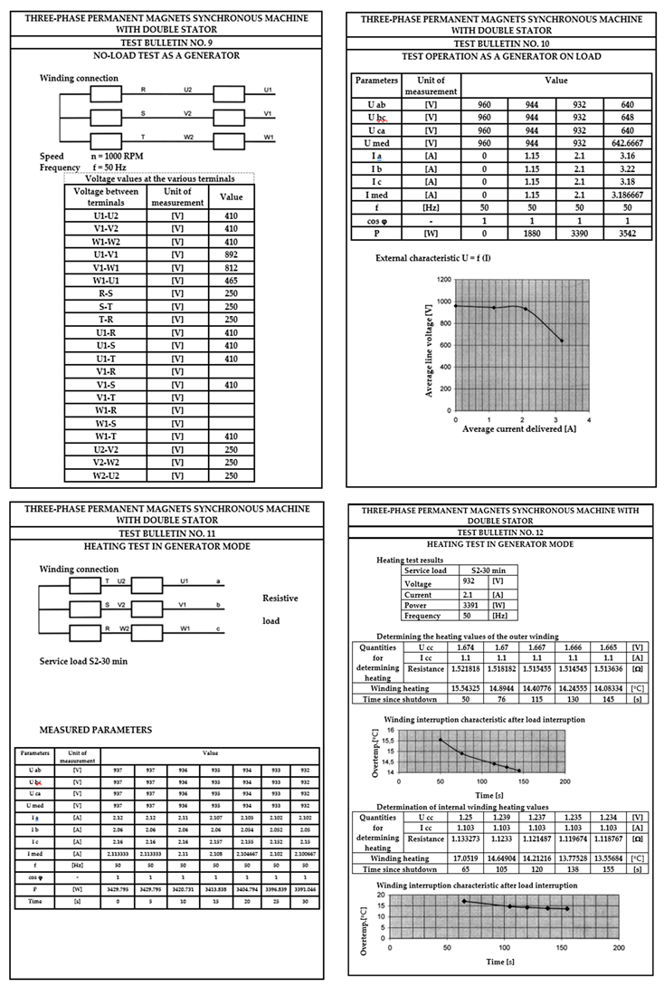
As for the asynchronous version, the laboratory tests and trials for the synchronous version were also carried out in the prototype laboratory of S.C. UMEB S.A. The test program and the results obtained are presented below:
SAMPLES PROGRAM
1. Coupling the synchronous machine with a DC motor.
2. Testing the synchronous machine as a generator with no-load operation.
3. Gradually rotating at a speed of 1000 rpm, the voltages at the terminals of the synchronous machine operating in no-load mode will be measured for different types of connections and between various points.
Figure 16.
Measurement of voltages at the terminals of the synchronous machine operating in no-load mode for different types of connections. (a) Schematic diagram; (b) Connection of terminals A and U; (c) Connection of terminals A and V; (d) Connection of terminals A and W; (e) Connection of terminals B and V; (f) Connection of terminals B and W; (g) Connection of terminals C and U.
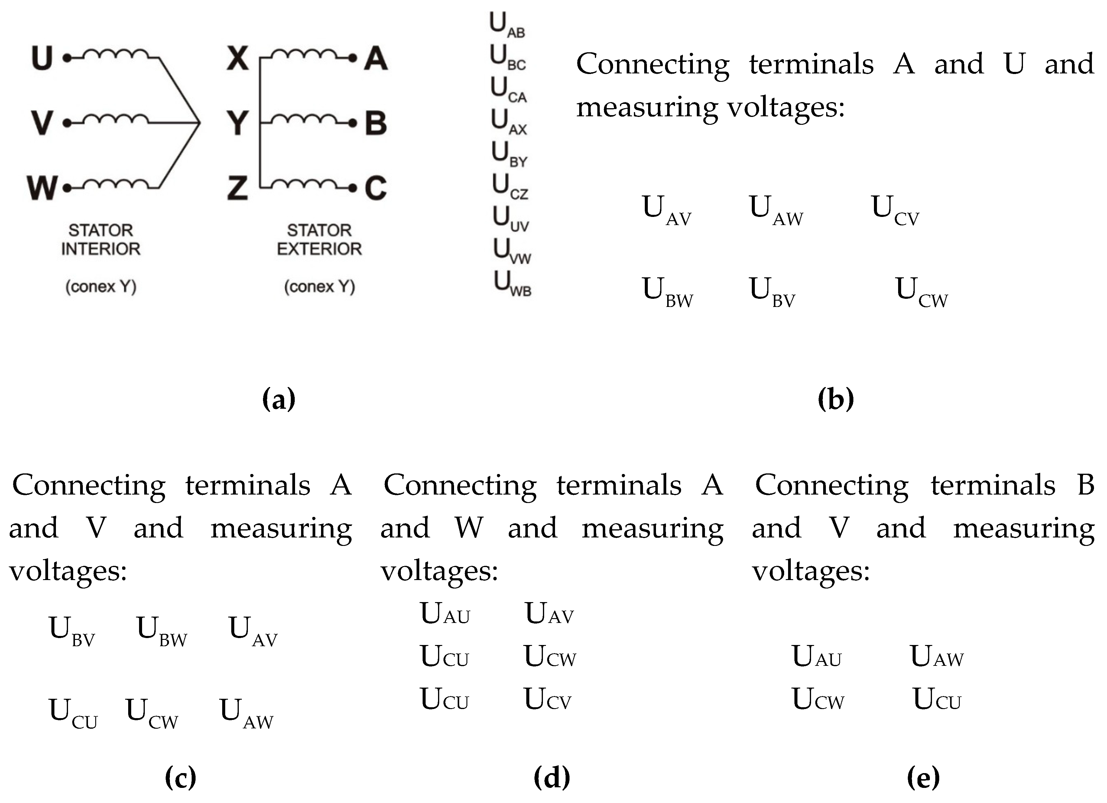
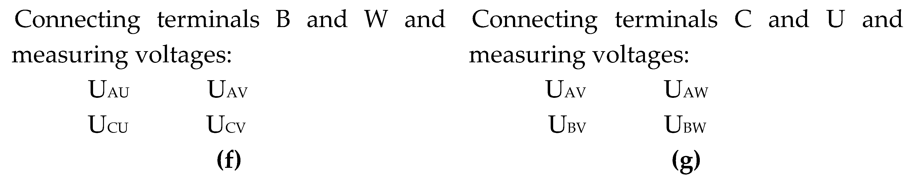
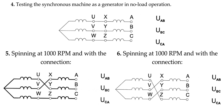
Figure 17.
Schemes for measuring voltages at no-load in generator mode. (a) ÷ (j) Different types of connections and their corresponding voltages.
Figure 17.
Schemes for measuring voltages at no-load in generator mode. (a) ÷ (j) Different types of connections and their corresponding voltages.
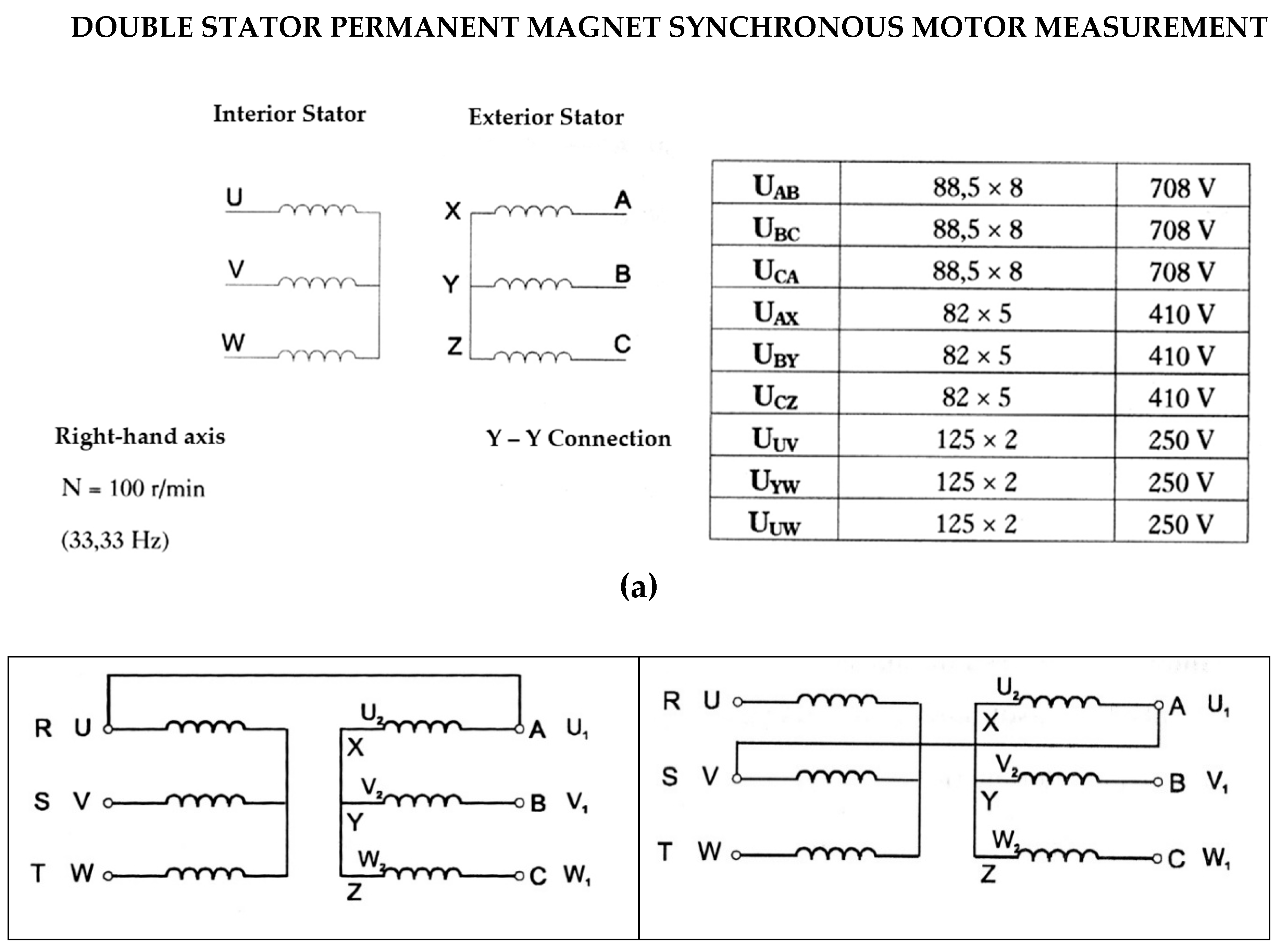
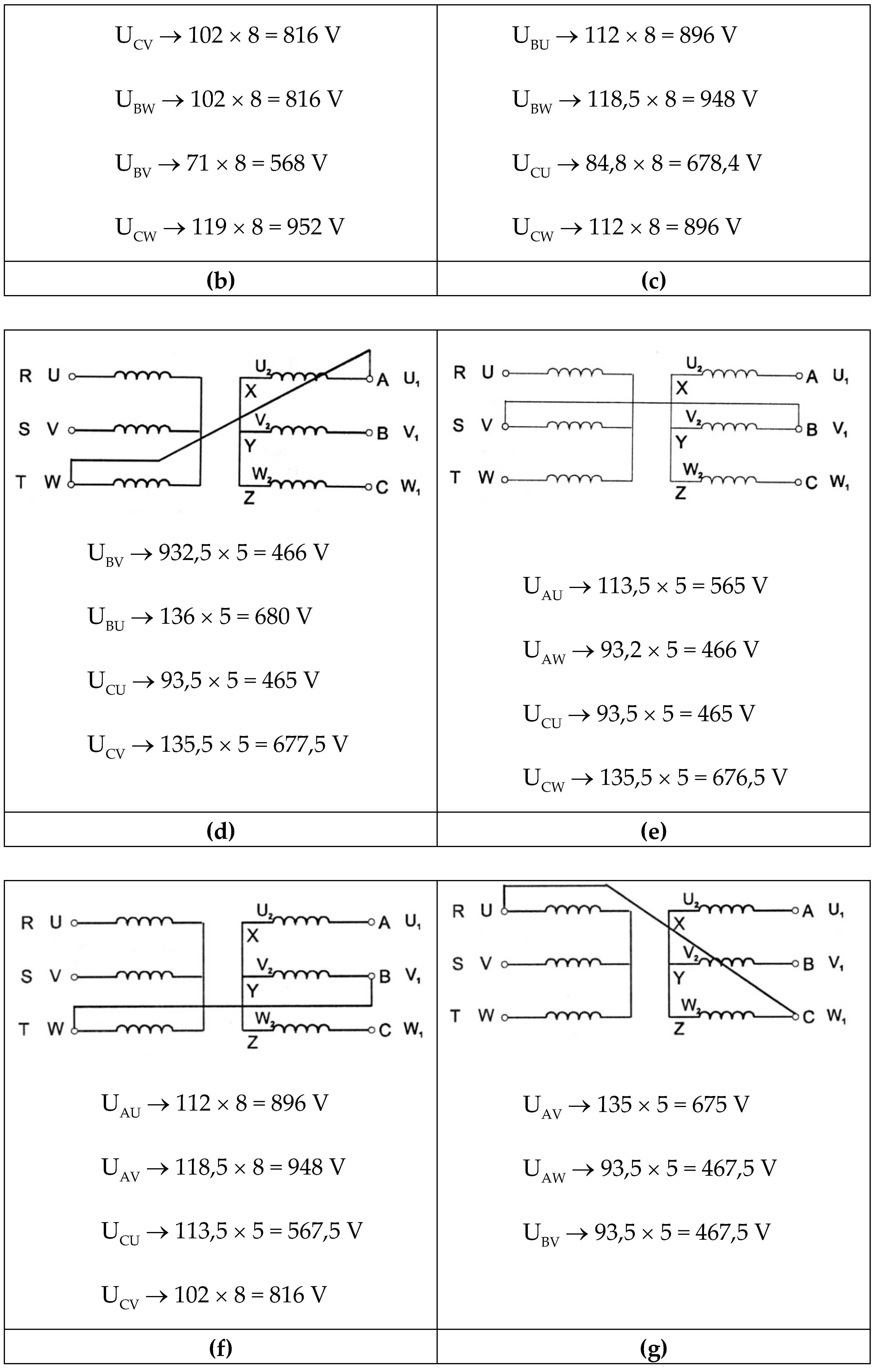
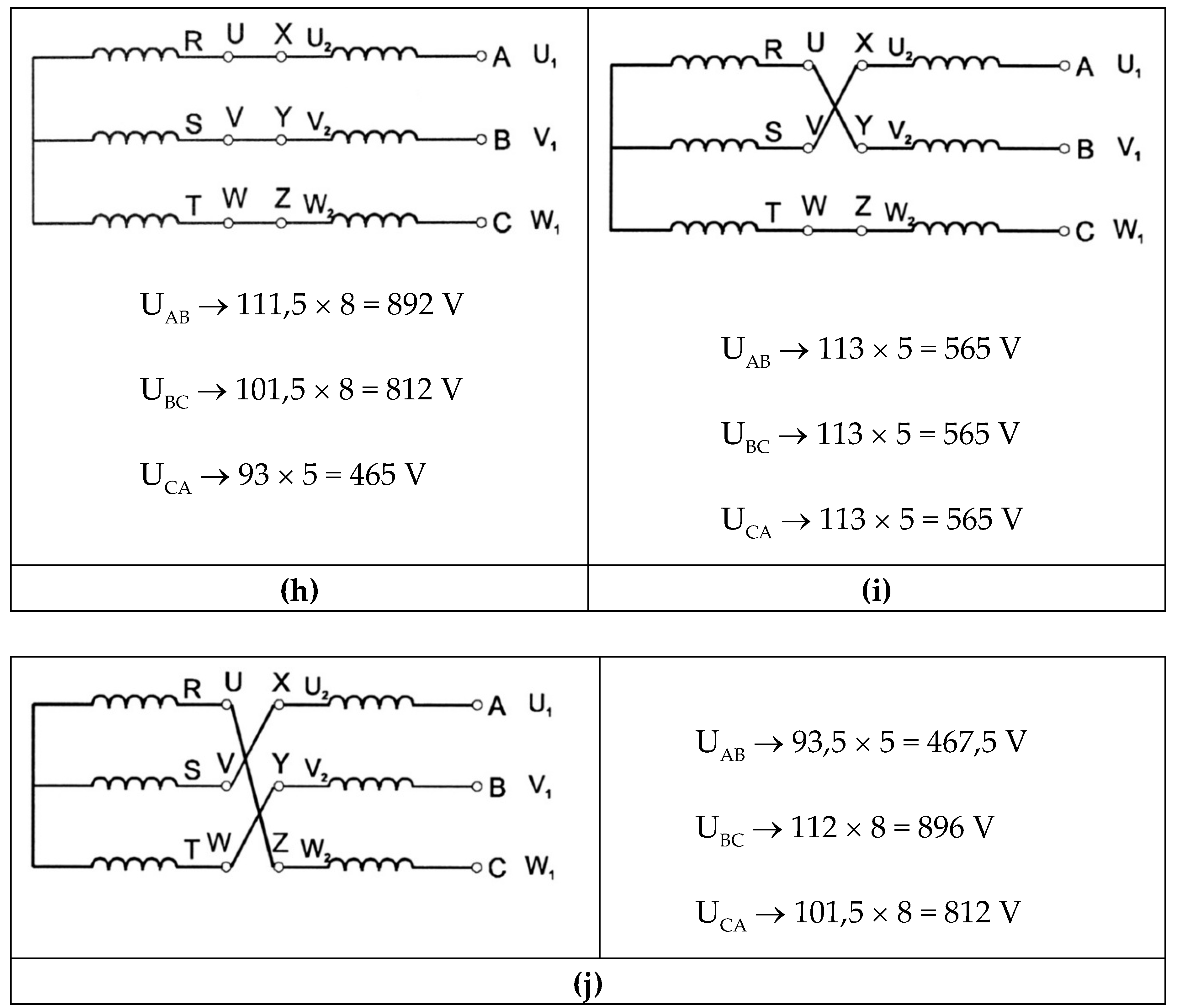
Below, the complete results of the measurements contained in the test reports prepared by the Laboratory of the Research Center of SC UMEB SA are presented.
4. Conclusions
As we have shown throughout this presentation, the proposed structure is equivalent to two classical permanent magnet synchronous machines, electrically connected in series and coupled on the same shaft. These elementary machines operate at the same autopilot angle, but the power factors and internal angles are different. Overall, however, the structure with the two stators behaves like a classical permanent magnet synchronous machine.
The two elementary machines can be separated by a cylindrical sectioning at the rotor level and studied separately. The analytical calculation model leads to slightly superior results to those obtained by numerical simulation (within the range of 5%).
By using a double surface of interaction of the rotor with the two stators, the electromagnetic torque and the active power are significantly superior to a classic machine with the same volume of active materials, even going as far as doubling the respective sizes. In addition, the cantilever rotor has a reduced inertia and is more robust in terms of mechanical construction, only the fixing of the magnets posing some technological problems.
The synchronous variant makes better use of the new structure, the reunion of the two machines being possible without modifying their transverse geometry. By fixing rare earth permanent magnets on both the outer and inner face of the rotor - made of solid steel pipe - significant fluxes are ensured that can be closed independently of each other. In this way, each active area of notches - air gap - permanent magnets can be used optimally.
In the synchronous version, the specific torques (Nm/kg of active material) increase impressively compared to synchronous motors with permanent magnets of normal construction. From a mechanical point of view, the rotor is more robust than in the asynchronous version, also benefiting from a reduced inertia.
The results of simulations using numerical methods and analytical calculations justify the conclusion that the proposed structure is of theoretical and practical interest, and the execution of a prototype with two interchangeable rotors will be able to confirm the technical and economic advantages of this solution.
Author Contributions
Conceptualization, M.-F.S. and I.B.; methodology, M.-F.S., I.B. and T.I; software M.-F.S., I.B. and T.I; validation, M.-F.S., I.B.; formal analysis, I.B. and T.I.; investigation, M.-F.S., I.B., T.I.; resources, M.-F.S.; writing—original draft preparation, M.-F.S. and I.B.; writing—review and editing, M.-F.S., I.B., T.I.; visualization, I.B. and T.I.; supervision, M.-F.S. and I.B. All authors have read and agreed to the published version of the manuscript.
Funding
This research was funded by Valahia University of Targoviste, Romania.
Data Availability Statement
Data is contained within the article.
Conflicts of Interest
The authors declare no conflicts of interest.
References
- Heim, J.W.; Vander Wal, R.L. NdFeB Permanent Magnet Uses, Projected Growth Rates and Nd Plus Dy Demands across End-Use Sectors through 2050: A Review. Minerals 2023, 13(10), 1274. [Google Scholar] [CrossRef]
- Kaya, M. NdFeB Permanent Magnet Uses, An overview of NdFeB magnets recycling technologies. Current Opinion in Green and Sustainable Chemistry 2024, 46, 100884. [Google Scholar] [CrossRef]
- Kumari, A.; Sahu, S.K. A comprehensive review on recycling of critical raw materials from spent neodymium iron boron (NdFeB) magnet. Separation and Purification Technology 2023, 317, 123527. [Google Scholar] [CrossRef]
- Crozier-Bioud, T.; Momeni, V.; Gonzalez-Gutierrez, J.; Kukla, C.; Luca, S.; Rolere, S. Current challenges in NdFeB permanent magnets manufacturing by Powder Injection Molding (PIM): A review. Materials Today Physics 2023, 34, 101082. [Google Scholar] [CrossRef]
- Kaya, E.E.; Kaya, O.; Stopic, S.; Gürmen, S.; Friedrich, B. NdFeB Magnets Recycling Process: An Alternative Method to Produce Mixed Rare Earth Oxide from Scrap NdFeB Magnets. Metals 2021, 11(5), 716. [Google Scholar] [CrossRef]
- Lee, J.I.; Kim, Y.C.; Jang-Young Choi, J.Y.; Cho, H.W. Analysis of Electromagnetic–Mechanical Characteristics according to Shaft Materials of Permanent Magnet Synchronous Motor. Energies 2022, 15(21), 8046. [Google Scholar] [CrossRef]
- Kumar, R.; Murmu, R. Performance Analysis of Permanent Magnet Synchronous Motor. International Journal of Engineering Research & Technology (IJERT) 2020, 8(16), 16026.
- Nagamuneendra, P.; Haritha, K. A Review on Design and Control of Permanent Magnet Synchronous Motor. International Journal of Advance Research and Innovative Ideas in Education (IJARIIE) 2024, 10(6), 25460. [Google Scholar]
- Shangguan, X.; Xie, Y.; Wang, X.; Wang, Q. Characteristic Analysis and Optimization Design of Permanent Magnet Synchronous Motor with New Rotor Structure. International Core Journal of Engineering 2025, 11(6), 0026. [Google Scholar]
- Shen, Q.; Zhou, Z.; Li, S.; Liao, X.; Wang, T.; He, X.; Zhang, J. Design and Analysis of the High-Speed Permanent Magnet Motors: A Review on the State of the Art. Machines 2022, 10, 549. [Google Scholar] [CrossRef]
- Tun, M.Z.; Swe, P.L. Power Factor Correction with Synchronous Motor for Rice Mill. International Journal of Scientific Engineering and Technology Research (IJSETR) 2014, 03(07), 1150–1155. [Google Scholar]
- Ullah, A.; Pan, J.; Safeer Ullah, S.; Zhang, Z. Robust Speed Control of Permanent Magnet Synchronous Motor Drive System Using Sliding-Mode Disturbance Observer-Based Variable-Gain Fractional-Order Super-Twisting Sliding-Mode Control. Fractal Fract. 2024, 8(7), 368. [Google Scholar] [CrossRef]
- Khanh, P.Q.; Truong, V.A.; Huy-Anh, H.P. Extended Permanent Magnet Synchronous Motors Speed Range Based on the Active and Reactive Power Control of Inverters. Energies 2021, 14(12), 3549. [Google Scholar] [CrossRef]
- Joshi, Y.; Parikh, K. Permanent Magnet Synchronous Motor Drives Control Technology. International Journal of Engineering Research & Technology (IJERT) 2014, 2(10), 10054.
- Abdelaziz, I.M.; Mohamed, Y.S.; Zaki-Diab, A.A.; Shehata, E.G. High-Performance Control of Permanent Magnet Synchronous Motor under Different Modes of Operation. Journal of Advanced Engineering Trends (JAET) 2023, 42(2), 245–254. [Google Scholar]
- Vannini, A.; Simonelli, C.; Marfoli, A.; Papini, L.; Bolognesi, P.; Gerada, C. Modelling, Analysis, and Design of a Line-Start Permanent Magnet Synchronous Motor. 2022 International Conference on Electrical Machines (ICEM) 2022. [Google Scholar] [CrossRef]
- Sarac, V.; Minovski, D.; Janiga, P. Parametric Analysis for Performance Optimization of Line-Start Synchronous Motor with Interior Asymmetric Permanent Magnet Array Rotor Topology. Electronics 2022, 11(4), 531. [Google Scholar] [CrossRef]
- Zöhra, B.; Akar, M.; Eker, M. Design of a Novel Line Start Synchronous Motor Rotor. Electronics 2019, 8, 25. [Google Scholar] [CrossRef]
- Sethupathi, P.; Senthilnathan, N. Comparative analysis of line-start permanent magnet synchronous motor and squirrel cage induction motor under customary power quality indices. Electrical Engineering 2020, 102(3), 1339. [Google Scholar] [CrossRef]
- Muteba, M. Dual Stator Dual Rotor Interior Permanent Magnet Synchronous Motor for Hybrid Electric Vehicles. 2020 IEEE Transportation Electrification Conference & Expo (ITEC), ISSN: 2377-5483, 23-26 June 2020.
- Li, C.; Guo, X.; Fu, J.; Fu, W.; Liu, Y. Design and Analysis of a Novel Double-Stator Double-Rotor Motor Drive System for In-Wheel Direct Drive of Electric Vehicles. Machines 2022, 10(1), 27. [Google Scholar] [CrossRef]
- Diao, T. Study on Dual-Rotor Permanent Magnet Induction Motor and Performance. The Open Electrical & Electronic Engineering Journal 2015, 9(1), 584-590.
- Flah, A.; Khan, I.A.; Agarwal, A.; Sbita, L.; Simoes, M.G. Field-oriented control strategy for double-stator single-rotor and double-rotor single-stator permanent magnet machine: Design and operation. Computers & Electrical Engineering, Volume 90, March 2021, 106953.
- Wu, J.; Hu, Y.; Zhang, B.; Feng, G.; Liu, Z.M. Comparison and analysis of different rotor structures of double-stator permanent magnet synchronous motor. IET Electric Power Applications, June 2022, 16(6), 685–700. [Google Scholar] [CrossRef]
- Jeong, K.I.; Heidari, R; Kang, D.H.; Ahn, T.J.; Park, G.S.; Ahn, J.W.; Lukman, G.F. Electromagnetic Characteristics of Dual-Air-Gap Surface Permanent Magnet Synchronous Motor. Machines 2023, 11, 717.
- Zhu, M.; Wu, L.; Liu, D.; Yiming Shen, Y.; Li, R.; Wen, H. Comparative Study of Dual-Stator Permanent Magnet Machines with Different PM Arrangements and Rotor Topologies for Aviation Electric Propulsion. Machines 2025, 13(4), 273. [Google Scholar] [CrossRef]
- Ran, Z.; Zi-Qiang Zhu, Z.Q.; Liang, D. Comparative Study of Dual-Rotor Permanent Magnet Machines with Series and Parallel Magnetic Circuits. World Electr. Veh. J. 2025, 16, 12. [Google Scholar] [CrossRef]
- Stan, M.F.; Bancuta, I.; Virjoghe, E.O.; Husu, A.G.; Cobianu, C. Unconventional Structures of Asynchronous Motors with Two Stators and Single-Rotor Radial Air Gaps in the Context of Their Applicability Assessment. Energies 2024, 17(24), 6237. [Google Scholar] [CrossRef]
- Hao, W.; Zhang, G.; Liu, W.; Liu, H.; Wang, Y. Methods for Reducing Cogging Force in Permanent Magnet Machines: A Review. Energies 2023, 16(1), 422. [Google Scholar] [CrossRef]
- Yan, D.; Yan, Y.; Cheng, Y.; Guo, L.; Shi, T. Research on cogging torque reduction method for permanent magnet synchronous motor accounting for the magnetic pole edge effect. IET Electric Power Applications 2024, 18(1), 64–75, 12367.
- Anuja, T.A.; Arun Noyal Doss, M. Reduction of Cogging Torque in Surface Mounted Permanent Magnet Brushless DC Motor by Adapting Rotor Magnetic Displacement. Energies 2021, 14, 2861. [Google Scholar] [CrossRef]
- Caruso, M.; Di Tommaso, A.O.; Miceli, R.; Viola, F. A Cogging Torque Minimization Procedure for Interior Permanent Magnet Synchronous Motors Based on a Progressive Modification of the Rotor Lamination Geometry. Energies 2022, 15, 4956. [Google Scholar] [CrossRef]
Figure 1.
Permanent magnet synchronous motor with radial electromagnetic field.
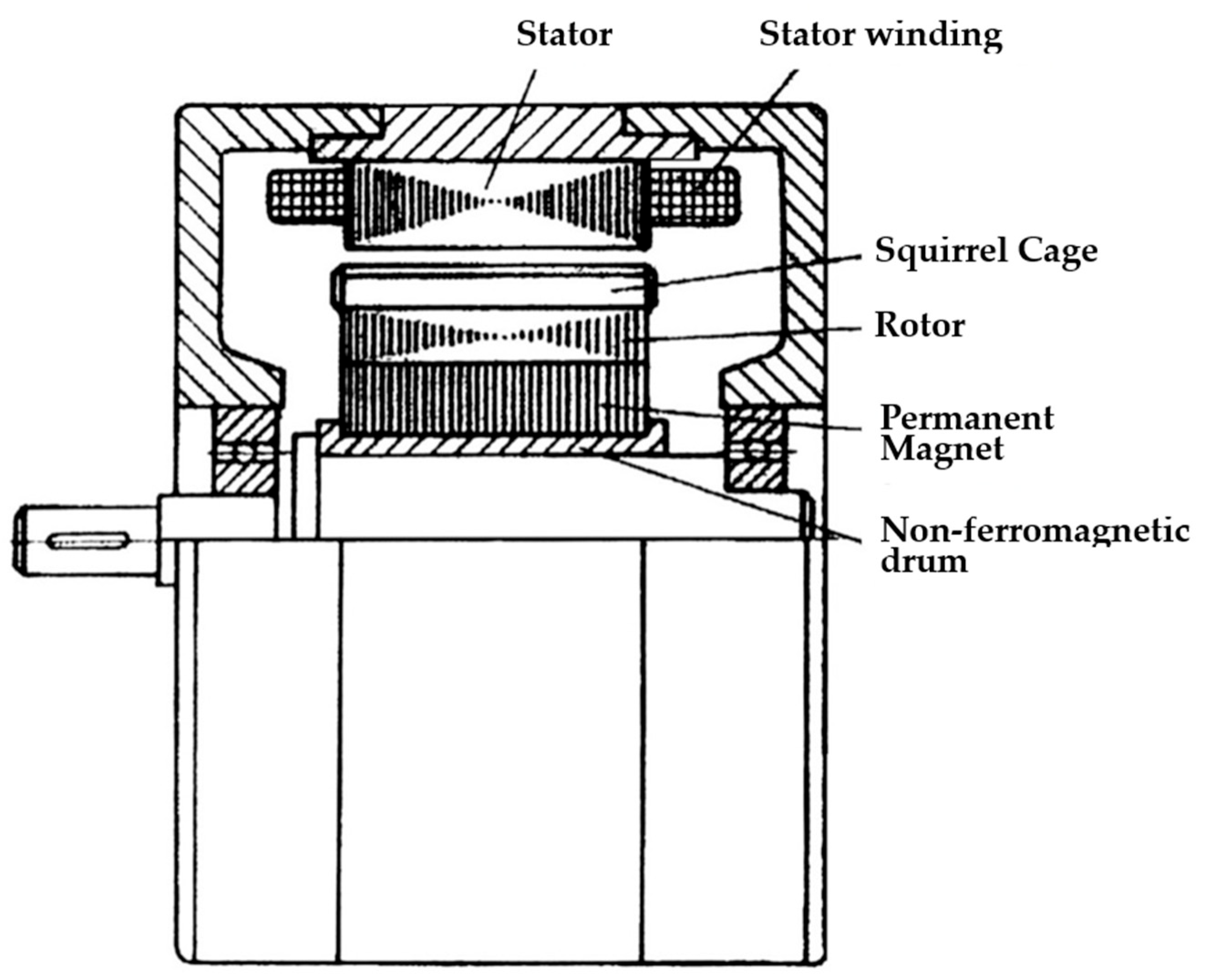
Figure 2.
Various rotor designs of permanent magnet motors. (a) Normal design; (b) With salient poles and squirrel cage.
Figure 2.
Various rotor designs of permanent magnet motors. (a) Normal design; (b) With salient poles and squirrel cage.
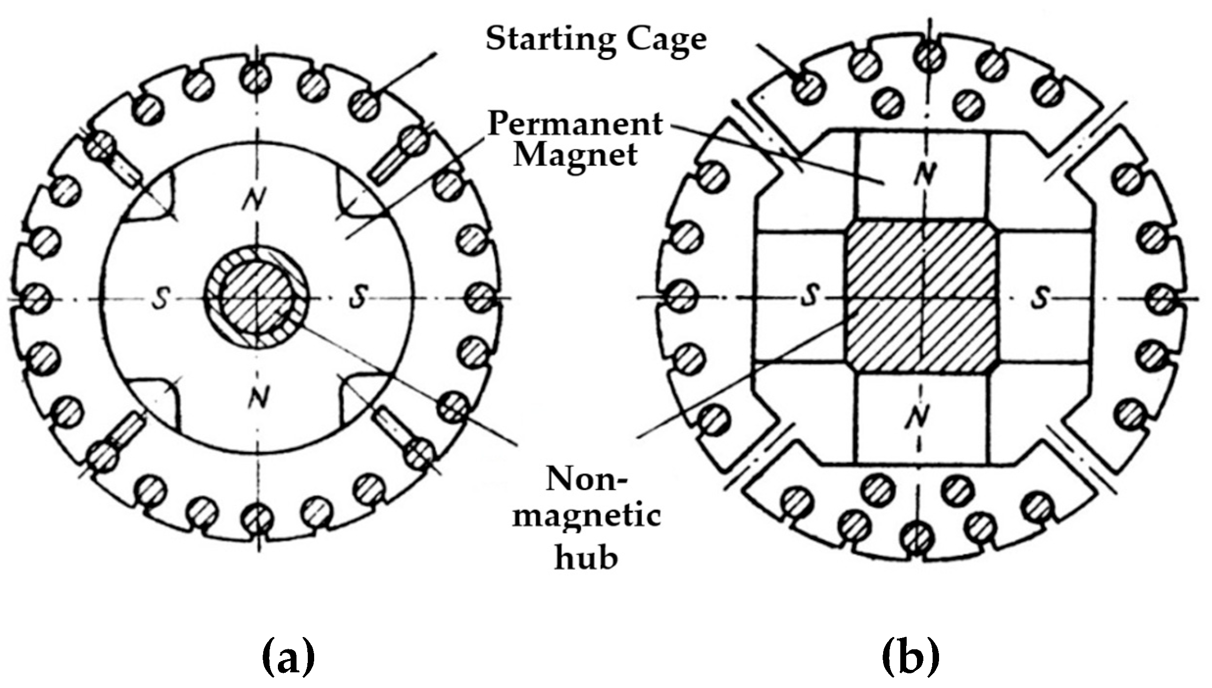
Figure 3.
Permanent magnet rotor. (a) Circular arrangement; (b) Zig-zag arrangement.
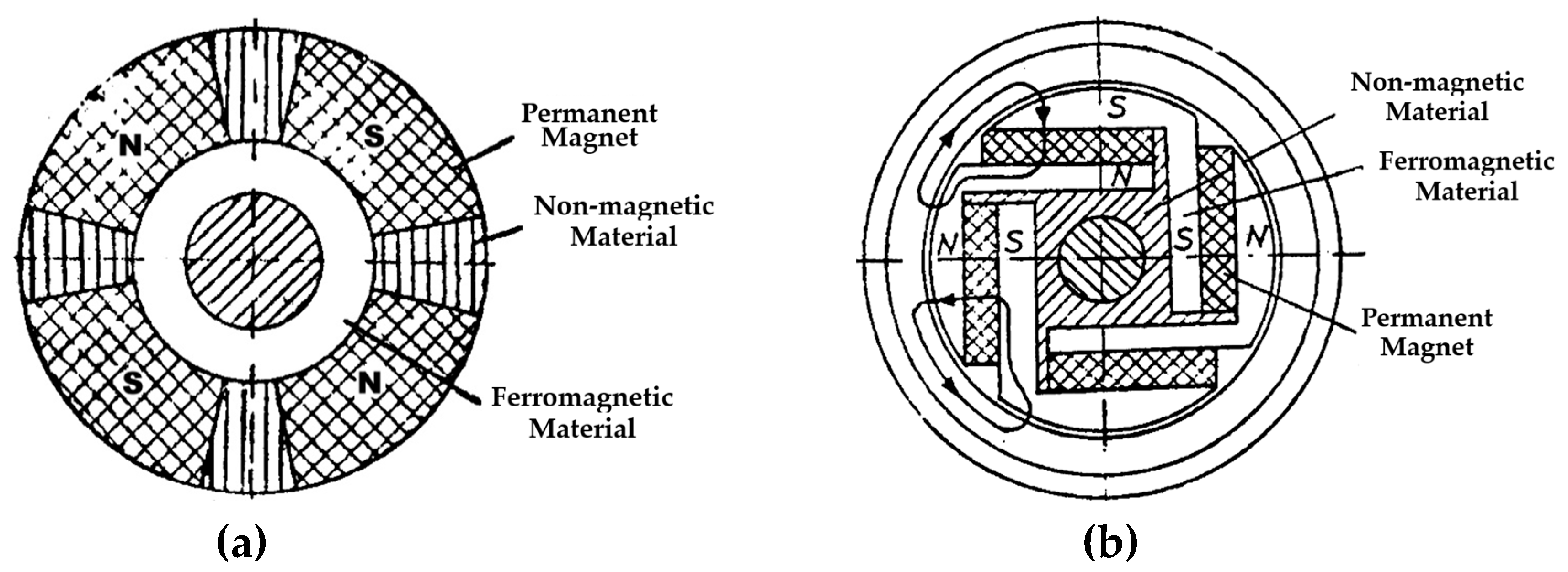
Figure 4.
Rotor with permanent magnets. (a) Positioned on the chord; (b) In the form of circular segments; (c) In polygonal form, with field weakening.
Figure 4.
Rotor with permanent magnets. (a) Positioned on the chord; (b) In the form of circular segments; (c) In polygonal form, with field weakening.
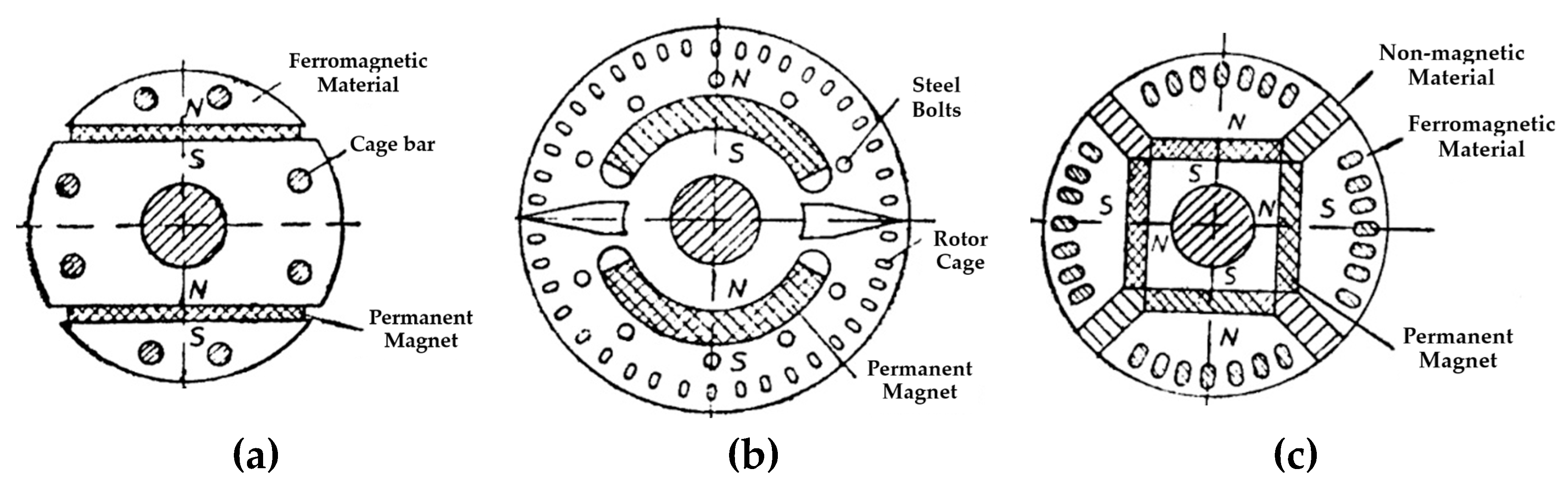
Figure 5.
Connection diagram of the stator windings. (a) Asynchronous version; (b) Synchronous version.
Figure 5.
Connection diagram of the stator windings. (a) Asynchronous version; (b) Synchronous version.
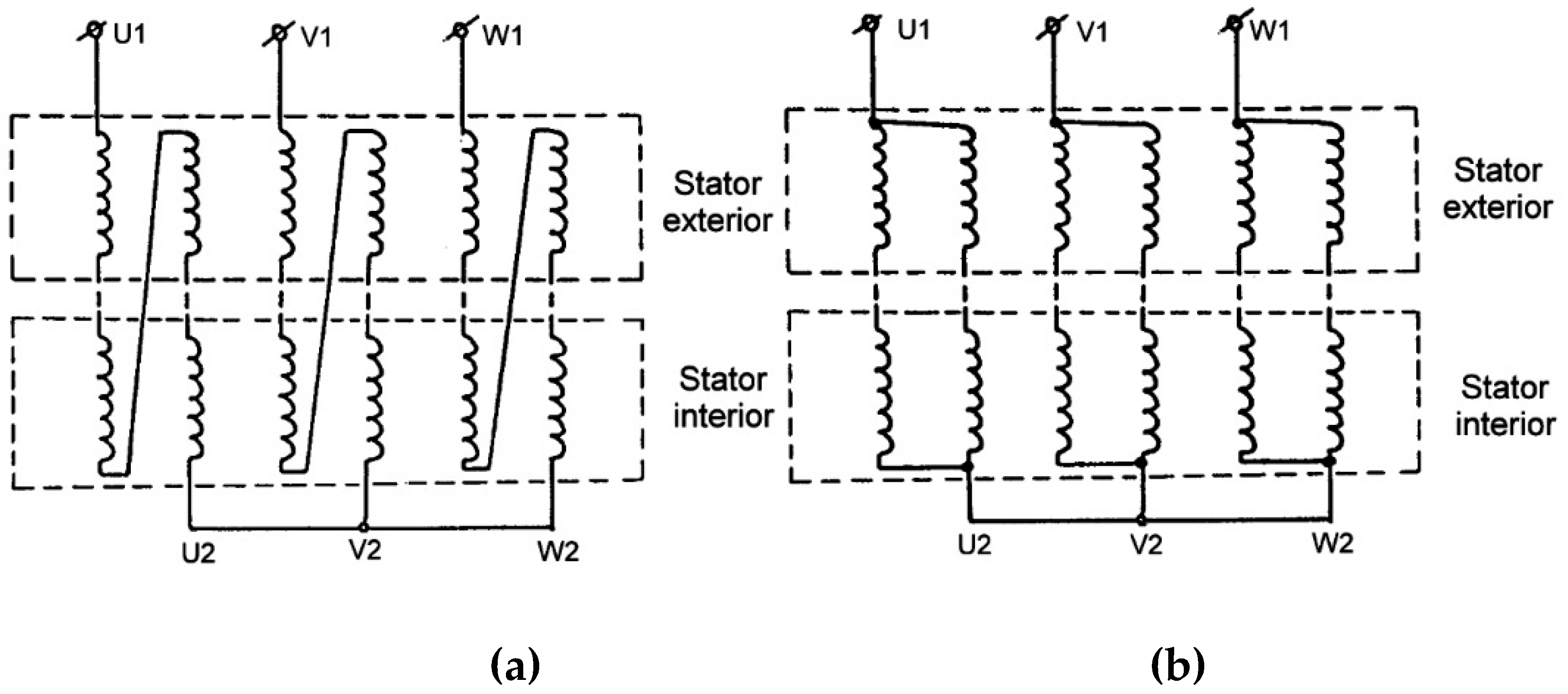
Figure 6.
Magnetic flux during no-load operation in the double-stator machine. (a) Asynchronous variant; (b) Synchronous variant.
Figure 6.
Magnetic flux during no-load operation in the double-stator machine. (a) Asynchronous variant; (b) Synchronous variant.
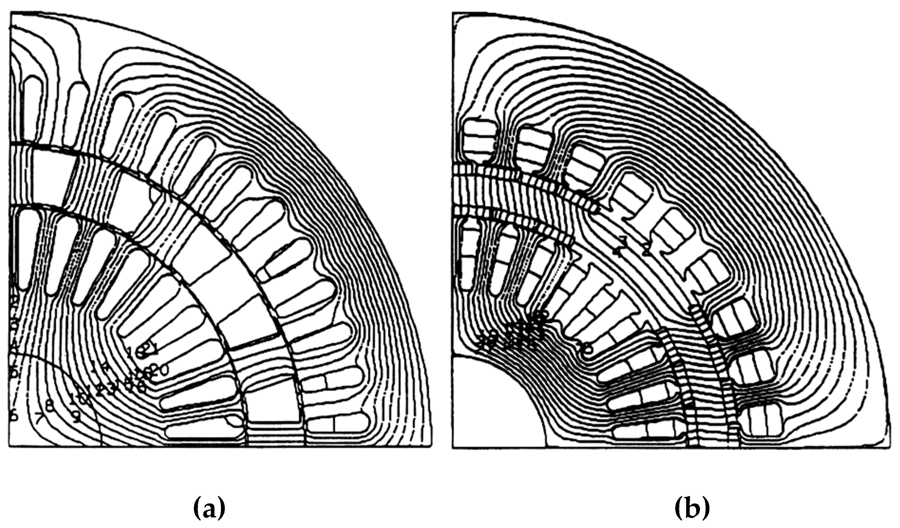
Figure 7.
Permanent Magnets Attachment Method.
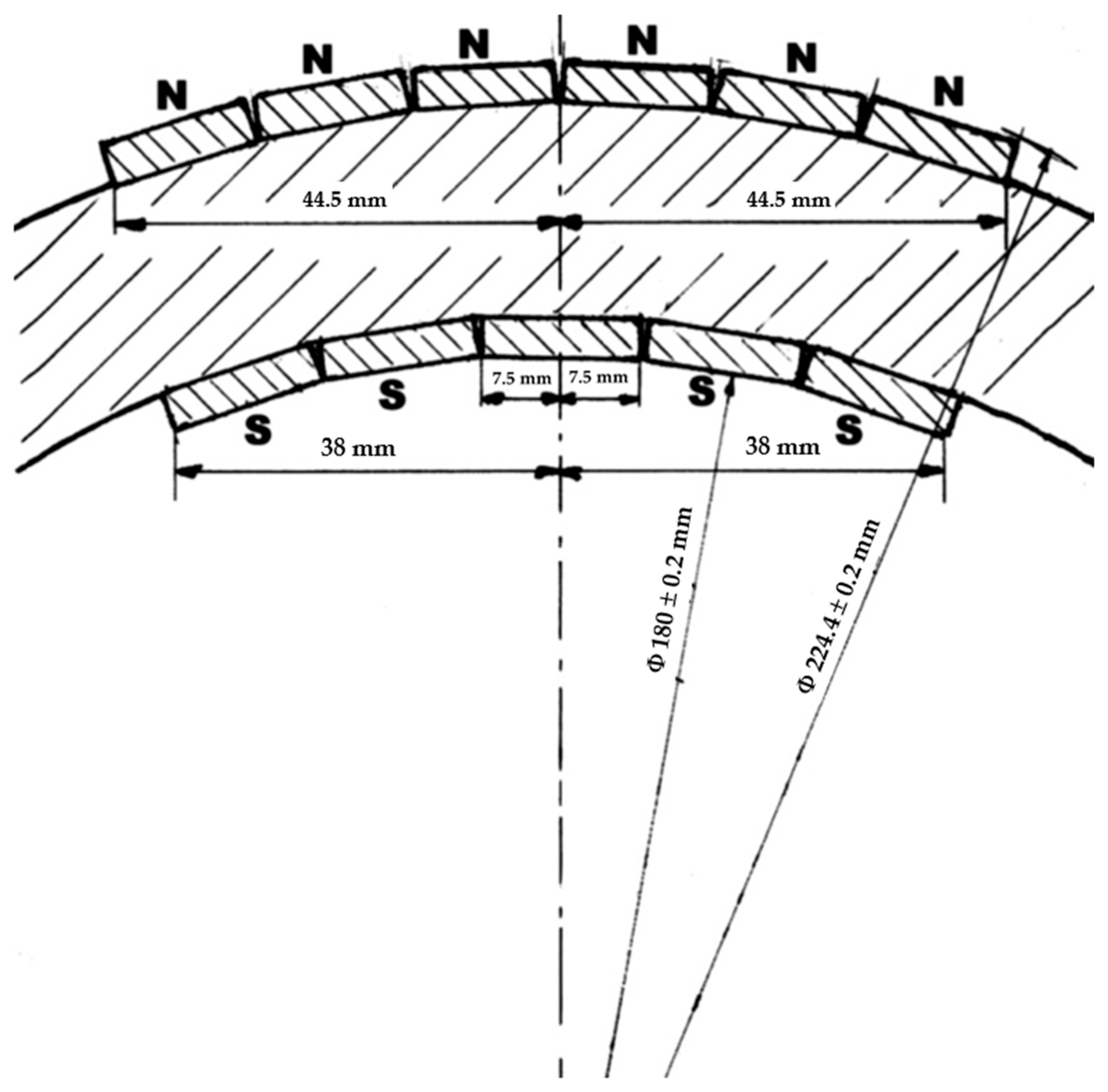
Figure 8.
Construction details of the rotor subassembly. (a) Milled cylinder rotor; (b) Rotor subassembly.
Figure 8.
Construction details of the rotor subassembly. (a) Milled cylinder rotor; (b) Rotor subassembly.
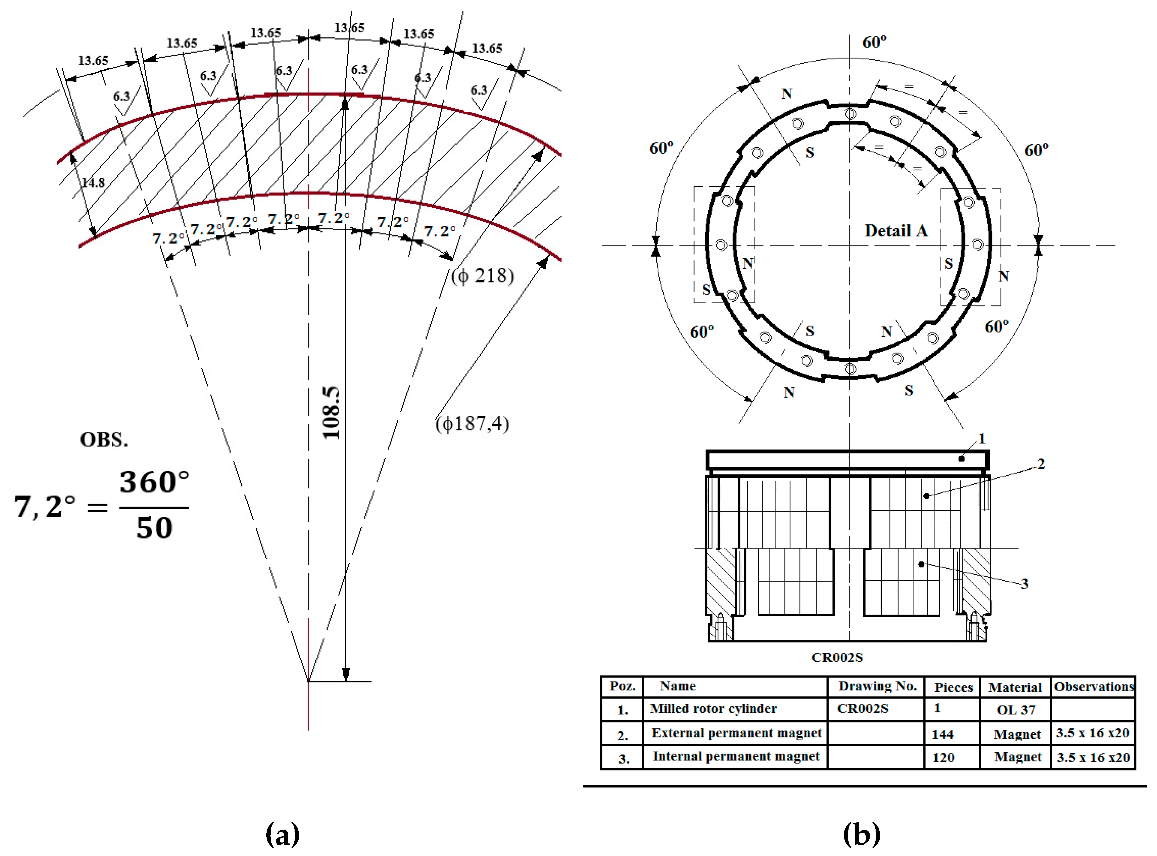
Figure 9.
Cogging torque. (a) For inner and outer poles; (b) Resultant torque.
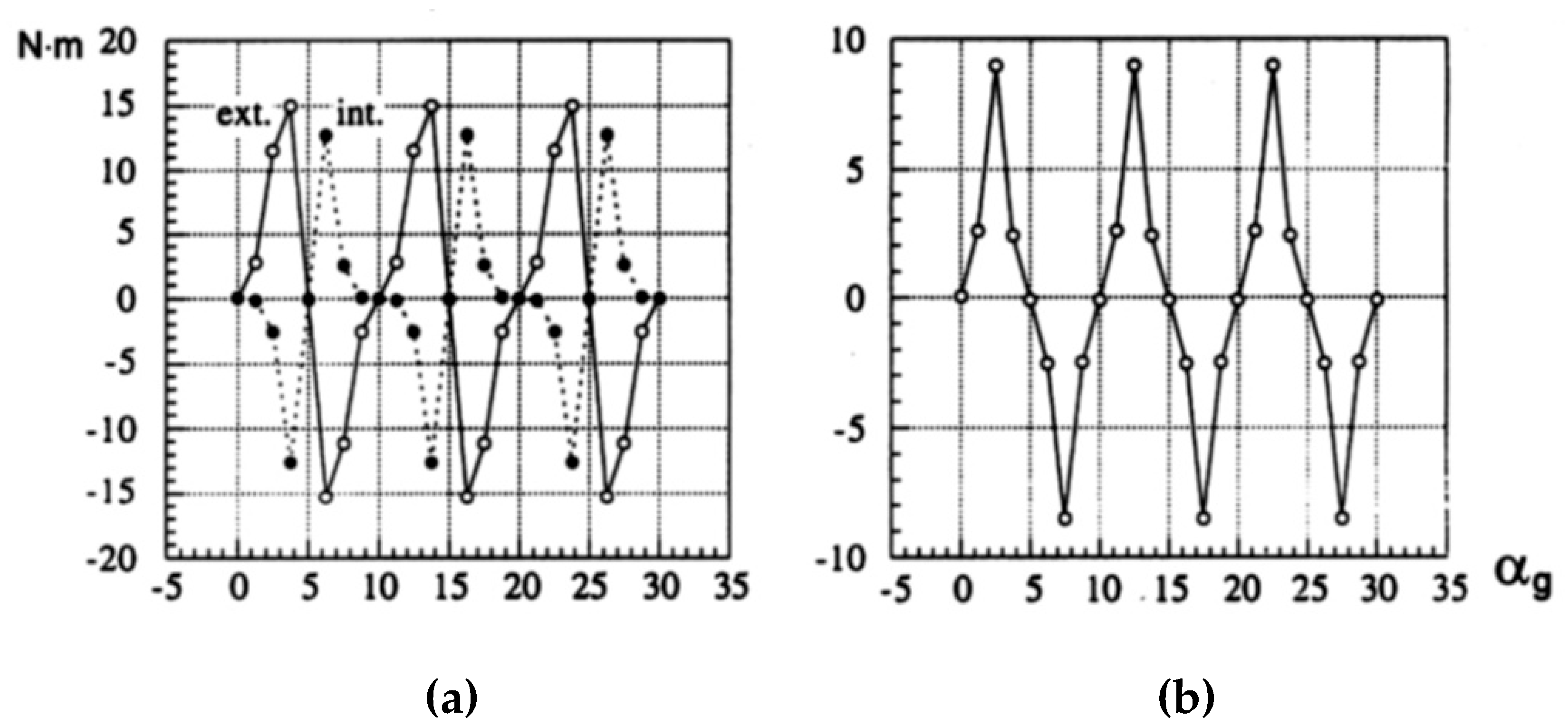
Figure 10.
Proposed transverse geometry. (a) Asynchronous variant; (b) Synchronous variant.
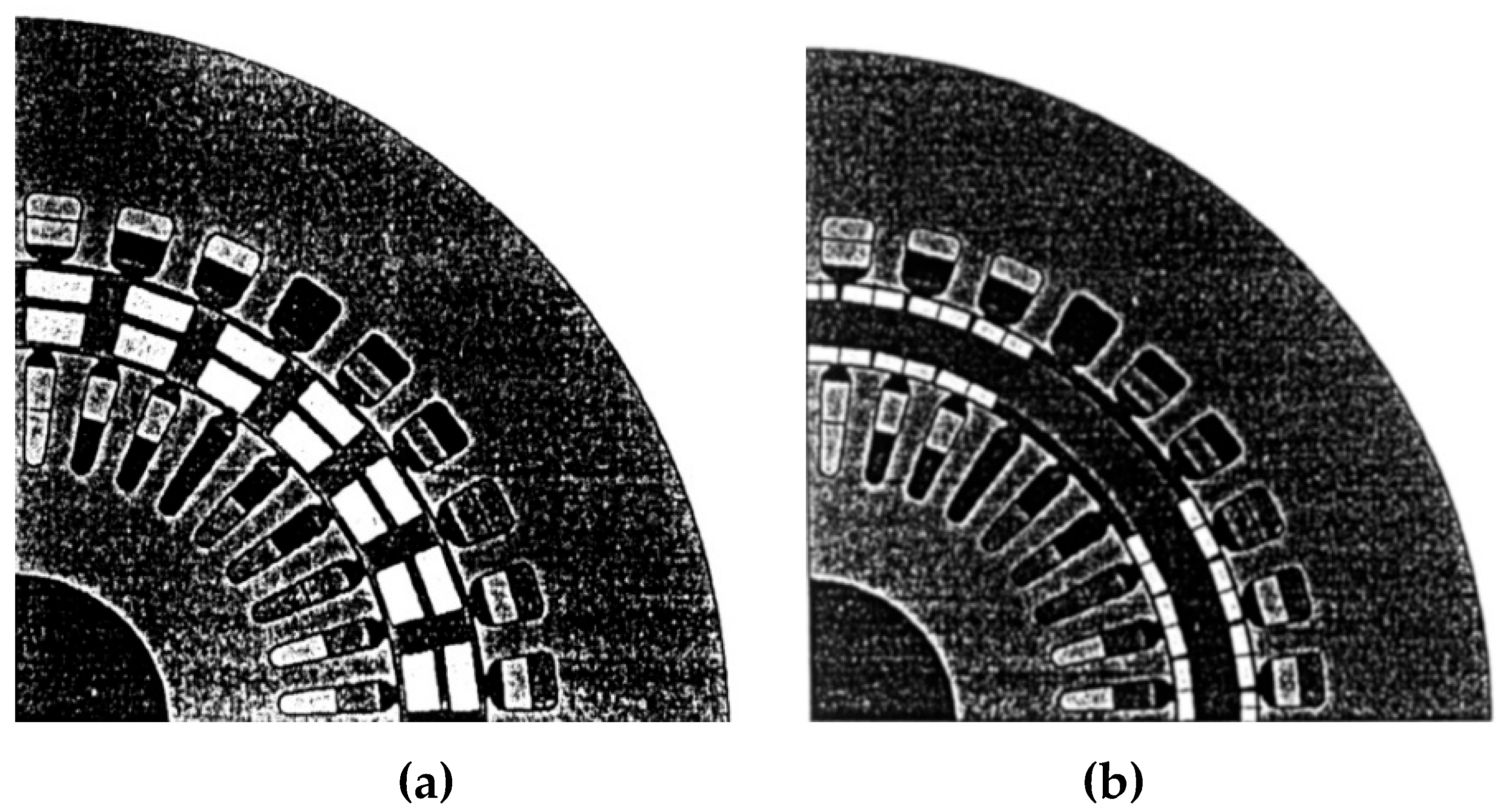
Figure 11.
Phasor diagram for load operating.
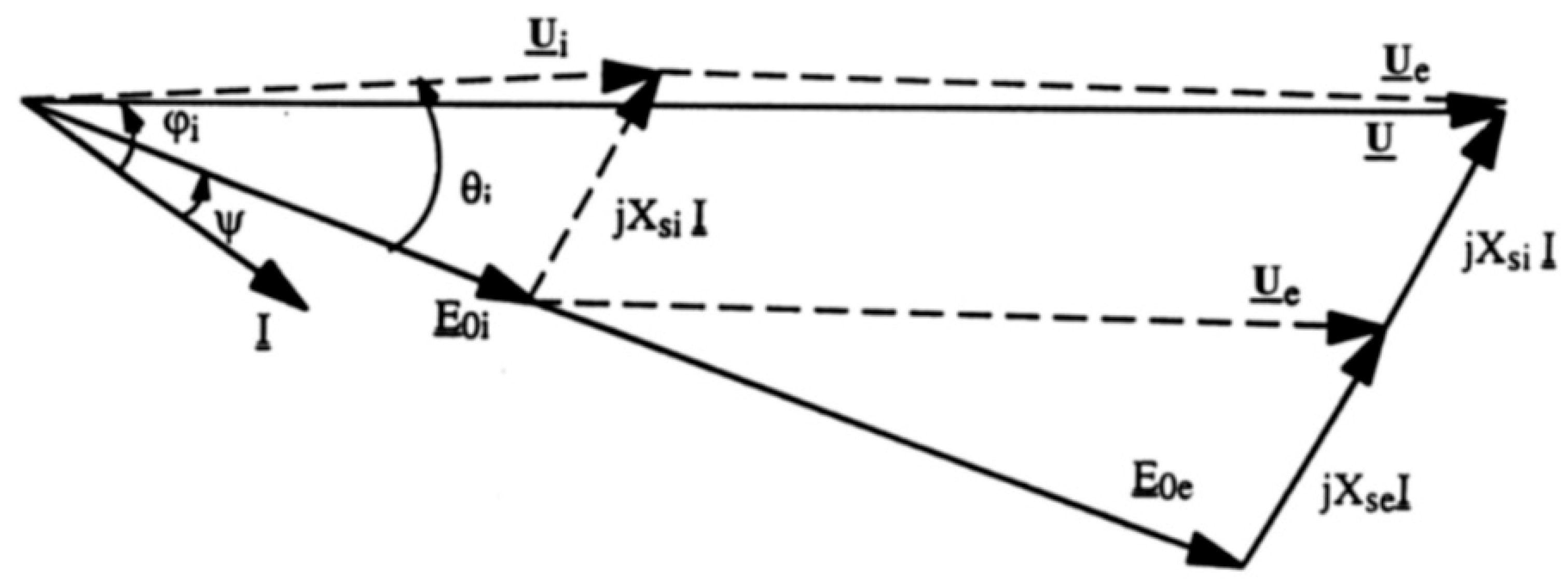
Figure 12.
Distribution of the induced reaction flux in the d-axis, in the absence of the inductive flux.
Figure 12.
Distribution of the induced reaction flux in the d-axis, in the absence of the inductive flux.
Disclaimer/Publisher’s Note: The statements, opinions and data contained in all publications are solely those of the individual author(s) and contributor(s) and not of MDPI and/or the editor(s). MDPI and/or the editor(s) disclaim responsibility for any injury to people or property resulting from any ideas, methods, instructions or products referred to in the content. |
© 2025 by the authors. Licensee MDPI, Basel, Switzerland. This article is an open access article distributed under the terms and conditions of the Creative Commons Attribution (CC BY) license (https://creativecommons.org/licenses/by/4.0/).
Copyright: This open access article is published under a Creative Commons CC BY 4.0 license, which permit the free download, distribution, and reuse, provided that the author and preprint are cited in any reuse.


