
Submitted:
01 August 2025
Posted:
01 August 2025
You are already at the latest version
Abstract
The main topic of this research work is essentially about what can happen to the spine when subjected to an axial load and the damage caused when the mechanical load capacity of the intervertebral discs is exceeded, giving the focus to the analysis by introducing it in the context of sports, in this case, weight lifting. The approach focuses on biomechanics, specifically how a weight affects the biological structure during a free squat. This common weightlifting exercise involves lowering the body into a seated position and then standing back up, with an Olympic bar supported on the T1 vertebra, with the purpose of creating an approach to understanding how the spine and intervertebral discs are directly affected. For this, a methodology is presented through which the model is obtained, its validation and the application of analysis through numerical simulation. Subsequently, the behaviour of the spinal column under pressure at different levels of force is observed and qualified. Various configurations of the spine were analysed, including the distribution of forces in the intervertebral discs and adjacent joints, using a 3D biomodel subjected to analysis in the finite element software ANSYS. The results show the effect that excessive forces can cause, giving way to injuries with a significant increase in pressure on the intervertebral discs, but mainly allowing the identification of critical areas where disc herniations can originate. This numerical simulation study seeks to prevent harmful conditions in the field of fitness by providing relevant information on possible spinal column injuries in loading scenarios, which could help in a better understanding and diagnosis of unexpected injuries.
Keywords:
numerical simulation
; biomodel
; vertebrae
; load
1. Introduction
Herniated discs are among the most common pathologies of the musculoskeletal system. Studies have estimated that between 1% and 5% of the world's population suffers from herniated discs. The age range is 30 to 50 years [1]. In 2011 [2], a study focusing on the adult population found that 2% of the population had a herniated disc diagnosed using imaging tools, and it is known that this percentage increases with advancing age. Currently, there is still relatively little research related to this area of the body and this important issue, as the spine plays a crucial role in the biomechanics of the human body, with its main objective being to support and connect the upper and lower body, providing stability and mobility [3].
However, even when it is very resistant, when constantly exposed to excessive loads, as occurs in some sports, the structure can be damaged, sometimes presenting injuries that are too serious since the symptoms they entail cause limitation of movement of the lower body, greatly reducing the quality of life of the affected person due to everything that an injured spine entails in the daily routine of any individual [4]. This case study aims to observe the behavior of the intervertebral discs in the middle of the back (thoracic area) being from T1 to T12 under computer simulation [5] thanks to technological advances it is possible to simulate a condition that could be harmful in the action of loading an Olympic bar by an individual in a widely used exercise called free squat (Figure 1); This numerical analysis was developed with the biomodel obtained from an individual in healthy conditions but can also be applied to a subject who already has some acquired damage or even a congenital pathology. Because of being able to perform an analysis by numerical simulation, it is not required to have a physical model or the manufacture of test pieces, which could be determined as versatility to reach the objective of observing this condition raised in addition to defining the critical points of the event, validating results with literature that is related to the behavior that is reflected with the damage when it is already diagnosed [6]. As in the other methods, values and data are obtained within a spectrum which indicates where an injury can most easily occur, thus obtaining accurate information to identify the most probable failure points in the delimited area more simply because by identifying stress concentrations, it is possible to define which are the most exposed points along the thoracic part of the spine, thus providing one more possibility of a simulation proposal that shows in each individual a prediction which part of their spine is most likely to be damaged before it happens.
The approach that focuses on the thoracic vertebrae is because there is not much research regarding the area and detailed studies focus mainly on the lower part of the spine but not as such on the structure that comprises what is called the rib cage, probably because the lower back is the most prone to injury, but that does not prevent this pathology from occurring in the middle part, generating the problem of initially ruling out that area, which can leave it for a long time without being diagnosed or understood in detail, which worsens the conditions of the injury because it is not taken seriously enough. Emphasis is placed and pushed to increase the number of analyses of the thoracic area that thanks to the increase in computational resources, the possibility of increasingly complex studies opens up, which translates and supposes the obligation to define a greater number of areas to add in addition to more considerations to both elements and variables of the phenomenon, which will necessarily translate into results closer to reality, referring to the modes of compression generated in the vertebrae, intervertebral discs, spinal cord and the elements that make up this structure when practicing the sport of weightlifting, which is colloquially known as weightlifting. It is necessary to understand that the work currently offers only one of the many ways that exist in the behaviours that can occur in the vertebrae when subjected (Figure 2). Additionally, it is worth noting that various pathologies can make the spine more susceptible to damage, and the extent of damage can vary depending on the individual's posture, considering the angles at which the load is transmitted and whether it is evenly distributed. It is mentioned that in the case shown in the biomodel, a male individual is isolated, who can be considered to be in a healthy state, which can be used as a starting point for the development of increasingly complex case studies.
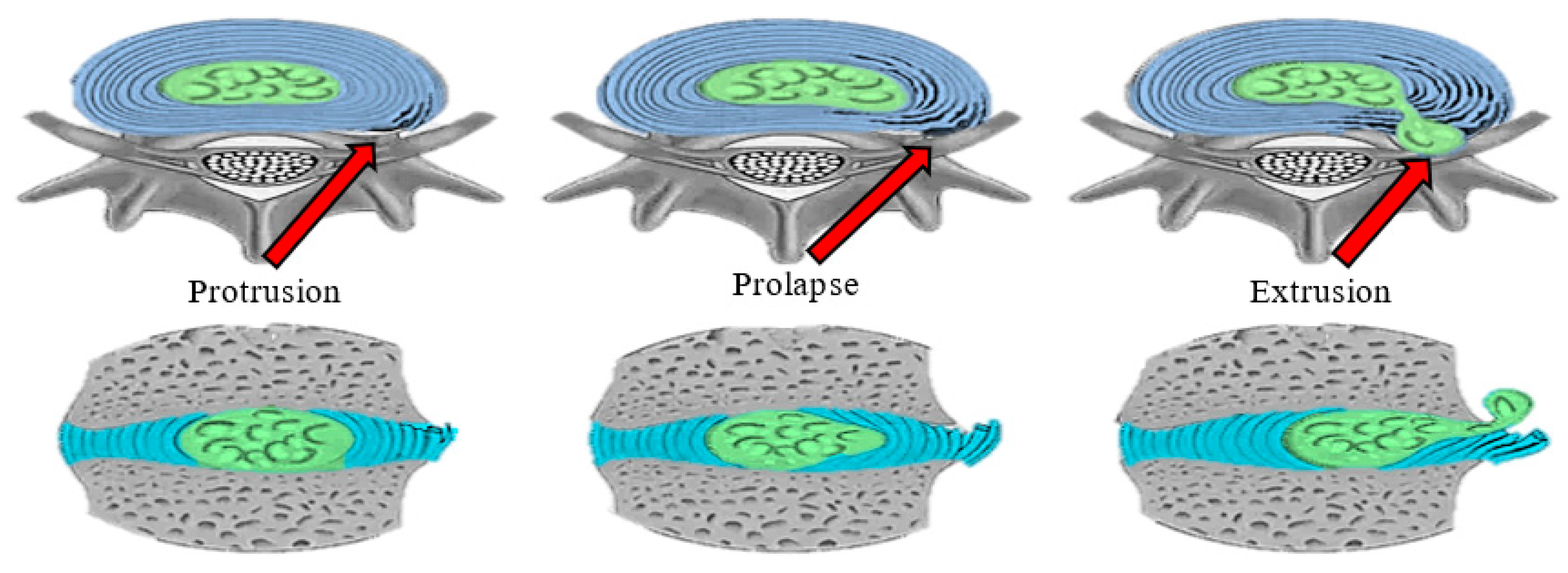
It can be understood that as its name indicates, the spine is a column-like structure with bone tissue components and a series of joints and cartilaginous tissue (intervertebral discs) that provides the support required to apply the proposed approach with a biomechanical approach as a tool that will be used in addition to being a highly influential factor in this analysis, describing the type of behavior that the elements will have when applying the load and the boundary conditions, in addition to adding the mechanical properties to the components. The results obtained from the computer program provide the pertinent information to define the direction of the injuries, enabling a comparison with reality. For the above reasons, we aim to clarify in which scenario a failure occurs in the vertebra or the intervertebral disc, as well as how it occurs, as illustrated in Figure 3. The literature has marked the phases of the advancement of failure in the intervertebral discs in 3 stages of damage (protrusion, prolapse and extrusion) with a later phase that corresponds to the moment in which the nucleus pulposus comes out completely and begins to irrigate through the space where the spinal cord is located [7], the failure of the intervertebral disc is usually due to wear and cyclic loading but it can also occur suddenly or due to wear reaching fatigue of the most exposed area.
2. Methodology
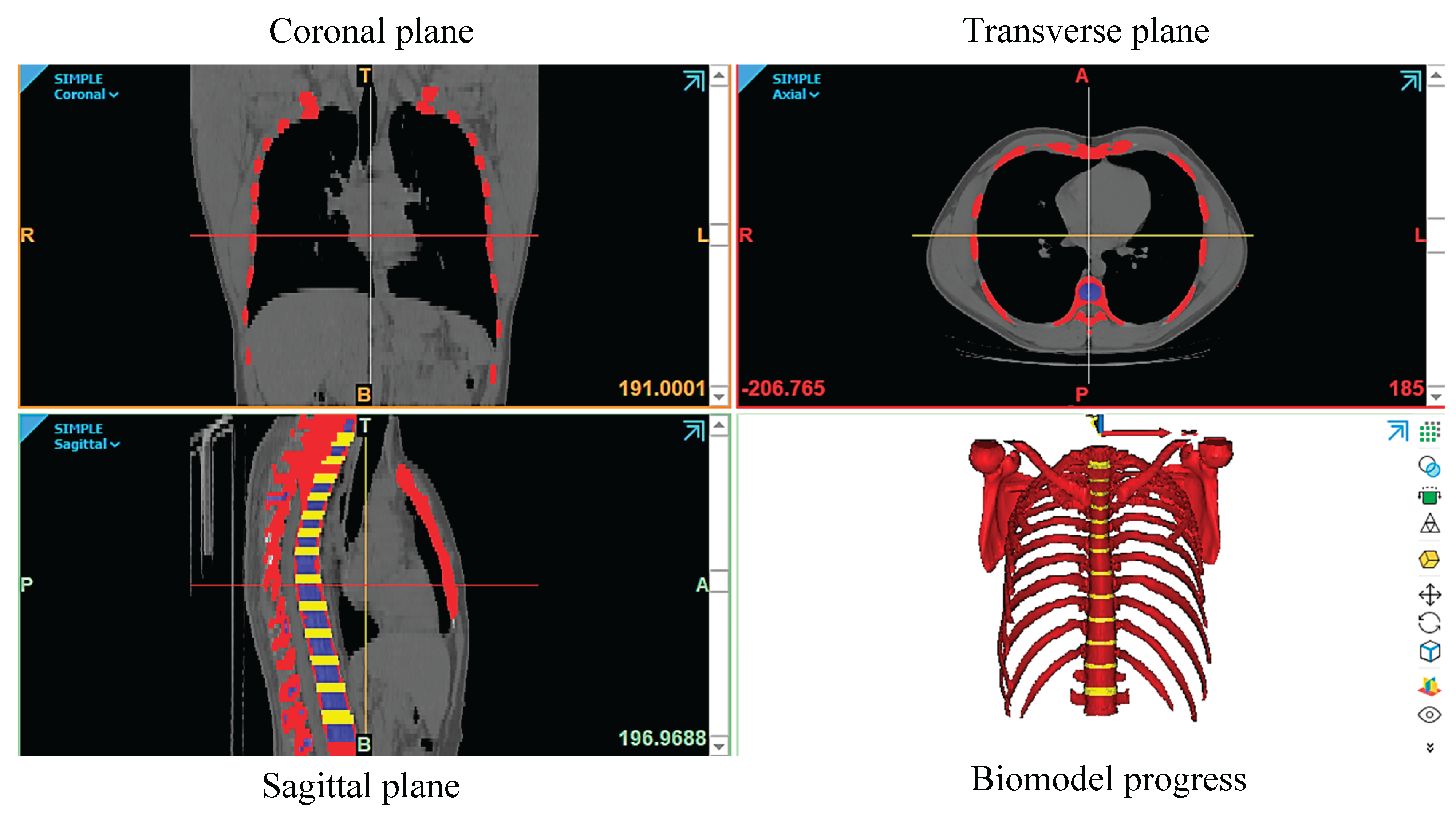
For the numerical analysis, a biomodel of the thoracic vertebrae (T1-T12) was obtained through a computer simulation. In this case, a 1.72 m tall male, weighing 80 kg, underwent a computed tomography scan. The scans provided images of the upper trunk, which comprises the sternum, ribs, costal cartilage, thoracic vertebrae, and spinal cord. These images were originally in DICOM format. These images must be exported to the software where the drawing is carried out, along with the biomodel design. The images are edited to remove imperfections and details. The images are then formatted in the software, using Mimics Research. The images are shown (coronal quadrant, transverse quadrant, and sagittal quadrant). as shown in Figure 3. Figure 3 shows the development of the biomodel where the red color represents the cortical bone of the vertebrae in addition to the ribs, yellow corresponds to the intervertebral discs, and blue represents the trabecular bone. Once the area of interest is drawn in the software, it is exported in STL format, but not before smoothing the surface of each component of the vertebral system that forms the biomodel. This was developed through the Mimics research® software. Subsequently, the 3matic research software allows for the addition and removal of features. As can be seen, cortical, trabecular bone, and intervertebral discs are considered because previous research has shown that damage to cortical bone and the fracture process are related to the deformation rate [8]. Additionally, the effects of loading rate, age, and morphology on the material properties of trabecular bone have been analysed [9]. The mechanical properties of human bones, including those of the vertebral bones, are fundamental to understanding their behaviour under load [10]. Finally, the validation of finite element models for biomechanical simulations provides a solid framework for such studies [11].
Figure 3 Tomografía torácica de individuo
Figure 4.
Human Thoracic CT Scan.
2.1. Biomodel
Obtaining a three-dimensional biomodel is crucial for understanding how it is created. It begins with the mechanical behaviour of the biological structure, including its shape, which is a crucial factor, as well as the dimensions that influence the proposed solutions to the pathology. This can be observed in various areas of the body. It is worth mentioning that while some areas of the body are more stressed than others, all are truly important, varying in their visibility. An example is the knee, which can be observed more clearly than the spine and also has multiple degrees of freedom, being a joint composed of a set of bones. Research in this field is continually supported by computed axial tomography, as it provides DICOM-type images of the anatomy for use. Subsequently, through various computer programs, these are transformed into 3D biomodels used to observe pathologies and design personalised prostheses. A clear example is the biomechanics group led by Dr. Guillermo Manuel Urriolagoitia Calderón at the National Polytechnic Institute [12]. Nowadays, through the methodology used, which consists of a series of steps already marked, increasingly detailed biomodels are obtained, counting on bone, cortical, trabecular, ligaments, tendons and even muscles, also when it is the area of the skull and neck, the cervical vertebrae accompanied by the skull have been obtained and on the other hand, in the same area, the mouth has been modeled accompanied by the dental pieces as well as its components, cortical bone and trabecular bone for the jaw and pulp for the teeth and molars: the crown, dentin and pulp [13]. In the short and medium term, this provides solutions because it allows for an in-depth observation of what is affecting it. Another advantage that may be the most important is that pieces called internal or external prostheses can be designed to fit the exact size of the biological structure. For instance, today extremely small pieces have been achieved, even when, in the past, there were significant considerations. It was even seen as unlikely that it would be achieved due to the type of surfaces, which could be porous, in addition to considering the humidity and the type of fabric [14].
Figure 5.
Biomodel Vertebrae Created with Different Masks.
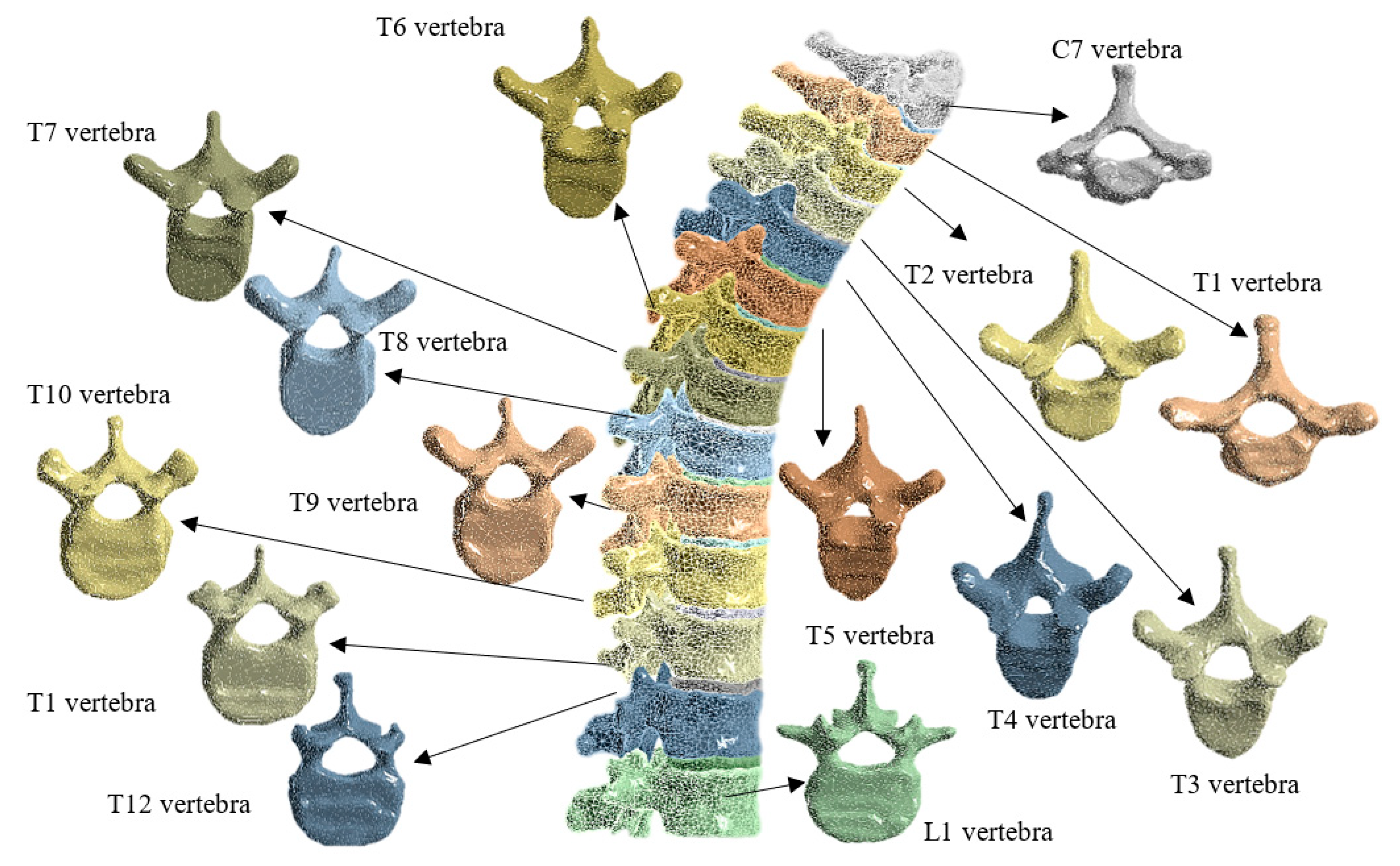
In the work the development of the biomodel was making a cut in the thoracic part respecting the part where the ribs are attached to the vertebrae, that is, the costovertebral joints located in the ribs being 12 pairs of ribs with the articulation between 2-9 and is respected in addition to the cut that is made to the ribs is to optimize computational resources in addition to obtaining a better focus since the objective of the analysis is to observe more clearly the thoracic vertebrae and their interaction with the intervertebral disc [15]. A biomodel of the spine was obtained using magnetic resonance imaging (MRI) and 3D scanning techniques, which respected the body as a shell, respecting its shape but not its real structure (skin, muscles, tendons, etc.). With this approach, we aim to gain a deeper understanding of how the anatomy functions within the body, rather than just examining the bones.
2.2. Mechanical Properties
Regarding the mechanical properties of the components, a literature review was conducted and validated through numerical analysis, mathematical verification, and experimental testing. It is worth noting that some methods may differ in their approach to obtaining data, and in some cases, the considerations for each method also vary. For example, in some studies, the tests are based directly on the type of material used. Bone tissue is an orthotropic material in the vertebral area. It is important to note that specimens must be tested in at least two directions. Some even propose testing vertebrae in tension [16]. The human body biomodel used in this study includes cortical and trabecular bone in the vertebrae, as well as intervertebral discs and ligaments. The mechanical properties are shown in the table below [17,18,19,20,21,22,23,24].

Table 1.
Mechanical Properties.
| Young's Modulus | Density (kg/m³) | Poisson's Ratio | Yield Strength (MPa) | Tensile Strength (MPa) | |
|---|---|---|---|---|---|
| Ribs | 13.9 GPa | 1561 | 0.3 | 93.9 | 124.2 |
| Sternum | 3.51 GPa | 1354 | 0.387 | 34.48 | 48.27 |
| Vertebra (cortical) | 17.4 GPa | 1500 | 0.3 | 52.62 | 69.06 |
| Costal cartilage | 19.92 GPa | 1203 | 0.4 | 141.32 | 285.94 |
| Vertebra (trabecular) | 181 MPa | 220 | 0.28 | 10 | 10 |
| Intervertebral disc (annulus fibrosus) | 500 MPa | 1090 | 0.30 | 16.0 | 2.94 |
| Intervertebral disc (nucleus pulposus) | 1 MPa | 1085 | 0.45 | 7.0 | 2.0 |
Once these properties have been added to the biomodel, the phenomenon from which data are being collected must be properly defined, as it requires an increasingly detailed understanding, including tissues such as muscles and their behaviour [24].
2.3. Numerical Analysis
Numerical simulations of three-dimensional models can be a truly important tool in terms of saving resources by helping to understand the behaviour of the structure being analysed more accurately.
Figure 6.
Initial Output of the 2D Analysis.

On the other hand, the analysis of the results reveals that, although they are not entirely accurate in certain cases, they can provide more accurate information when evaluating possibilities and choosing the most suitable one. For the analysis adopted in this work, numerical simulations were carried out using ANSYS software with the idea of evaluating the behaviour that the spine would have under the load of an Olympic bar and for this, different load rates were evaluated to observe how these affect the integrity of the vertebrae in addition to the intervertebral discs [25]. Numerical simulations were conducted using ANSYS Workbench software in its static structural analysis module to assess the biomechanical behaviour of the thoracic spine, from T1 to T12, under the axial load induced by an Olympic bar, as occurs during the free squat exercise. The biomodel previously generated in Mimics Materialise and refined in 3D Slicer was imported into the ANSYS environment in STL format and subsequently converted to a solid model for analysis using the Finite Element Method (FEM) [26].
Figure 7.
Components of the Load Applied in the 3D Analysis Depending on the Angle of Application.
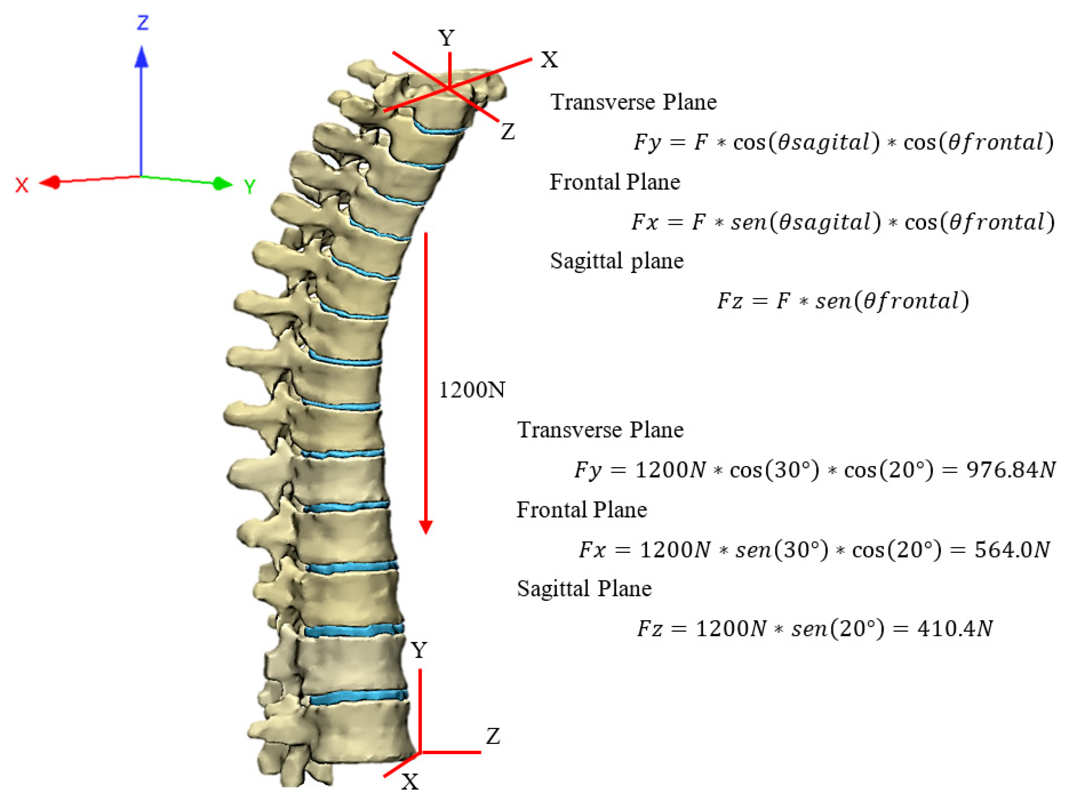
To ensure the fidelity of the simulation, a calculation was made of the estimated load area of 270 mm2 obtained from the size of the area in the C7 vertebra, translating it to meters as 2.7 × 10⁻⁴ m2 to obtain the pressure by dividing the force over the area as follows:
Table 2.
Components Given in Newtons and MPa.
| Component | Newtons | MPa en 2.7x10⁻⁴ m2 |
|---|---|---|
| X | 564.0 | 2.09 |
| Y | 976.84 | 3.62 |
| Z | 410.4 | 1.52 |
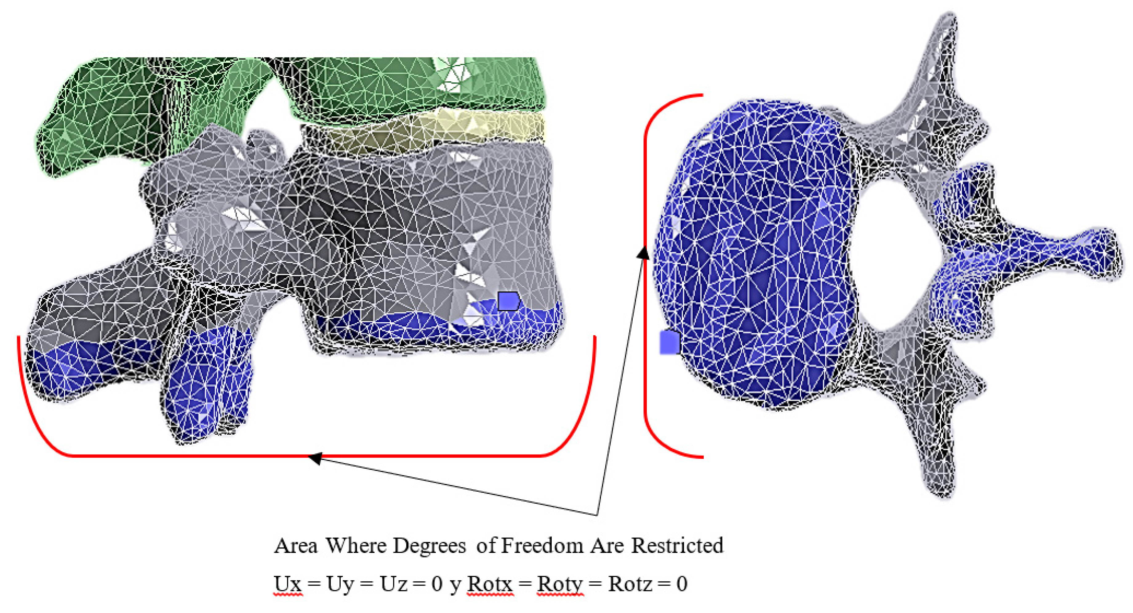
Subsequently, quadratic and high-order discretisation was generated with localised refinement in the intervertebral disc regions, given that these areas represent key points for analysing potential damage. Element size was optimised to maintain a balance between accuracy and computational resources, considering an average of 2 to 3 mm in cortical regions and refinements of up to 1 mm in the intervertebral discs. The mechanical properties assigned to the different components of the model included cortical bone, trabecular bone, intervertebral discs, sternum, and costal cartilage. They were defined based on data from specialised literature and validated experimentally (Table 1). Isotropic or orthotropic linear-elastic behaviour was assumed depending on the material. Boundary conditions were established by fixing the lower ends of the thoracic spine to simulate the connection with the lumbar region and pelvis. At the same time, the load was applied as a vertically distributed pressure on the T1 vertebra, representing the point of contact between the Olympic bar and the body during the exercise's execution. The load magnitudes analysed varied between 600 N and 1200 N, representing a realistic range of loads that an athlete may experience. That is, 61.16 kg and 122.33 kg, respectively [27].
Figure 8.
Boundary Conditions of Vertebra L1.
Multiple simulation scenarios were defined to evaluate the structural behaviour under different load magnitudes, thus allowing the identification of stress concentration zones, maximum deformations and possible failure points, with special attention to the intervertebral discs between the T6 and T9 vertebrae, an area in which a greater probability of occurrence of thoracic disc herniation is predicted [28].
3. Results
The simulation results indicated that the intervertebral discs exhibit failure points under specific loading situations. Results obtained from finite element analysis in ANSYS Workbench allowed for the observation of the distribution of stresses, deformations, and critical zones in the thoracic spine subjected to vertical loads simulating the lifting of an Olympic barbell.
Figure 9.
Overall Total Displacement of the Vertebral Column from T1 to T12 Under 120 kg Load.
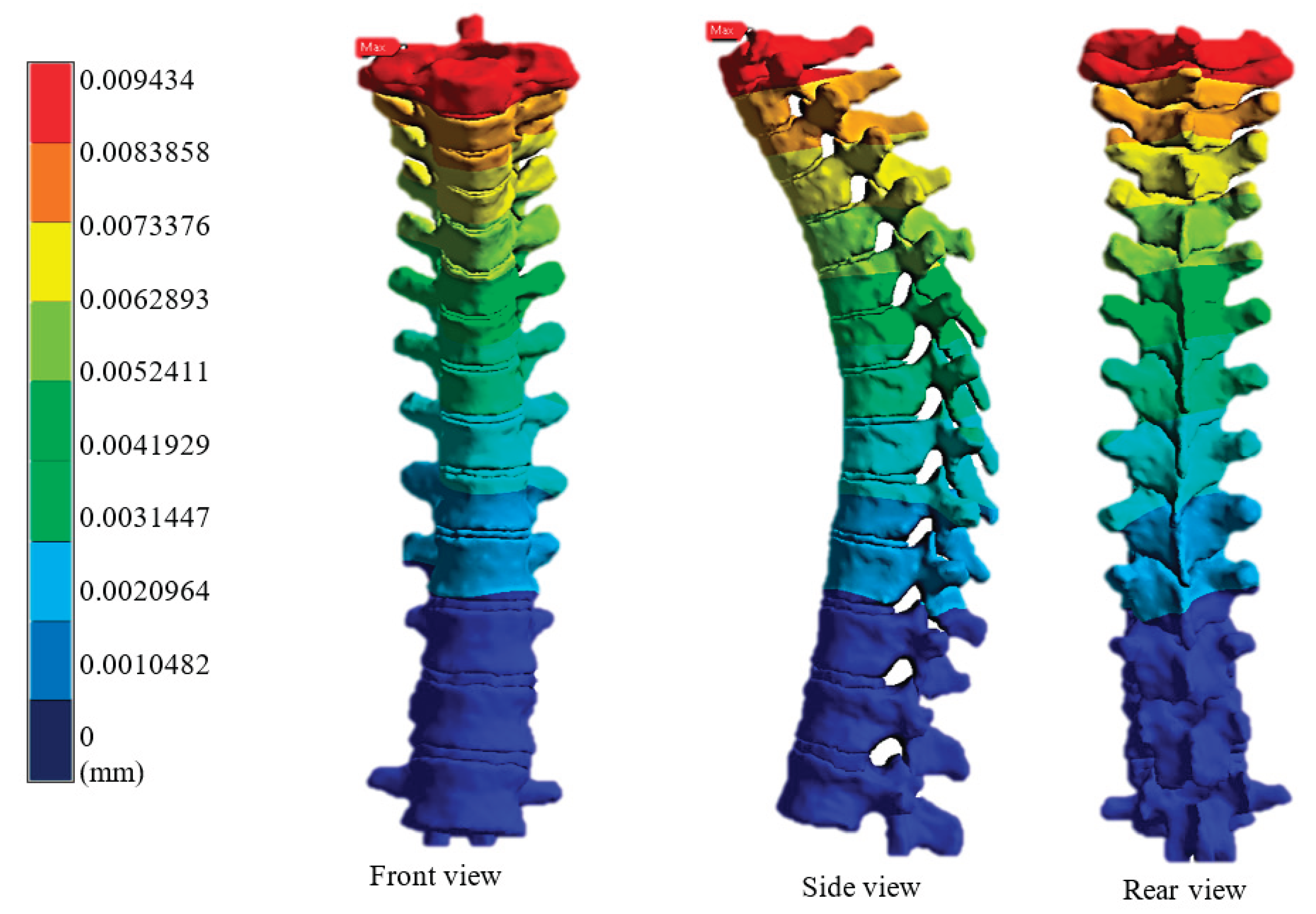
Figure 10.
Von Mises Stress of the Vertebral Column from T1 to T12 Under 120 kg Load.
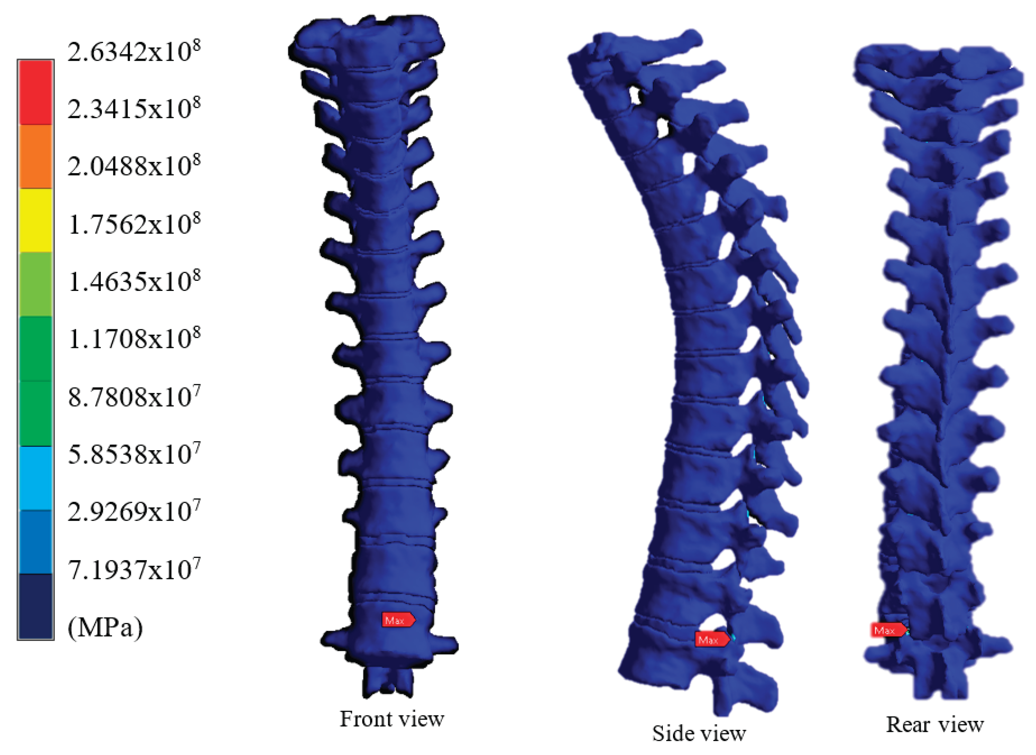
Figure 11.
Von Mises Stress with a Zoomed-In View of the Area with the Highest Stress, Vertebra L1.
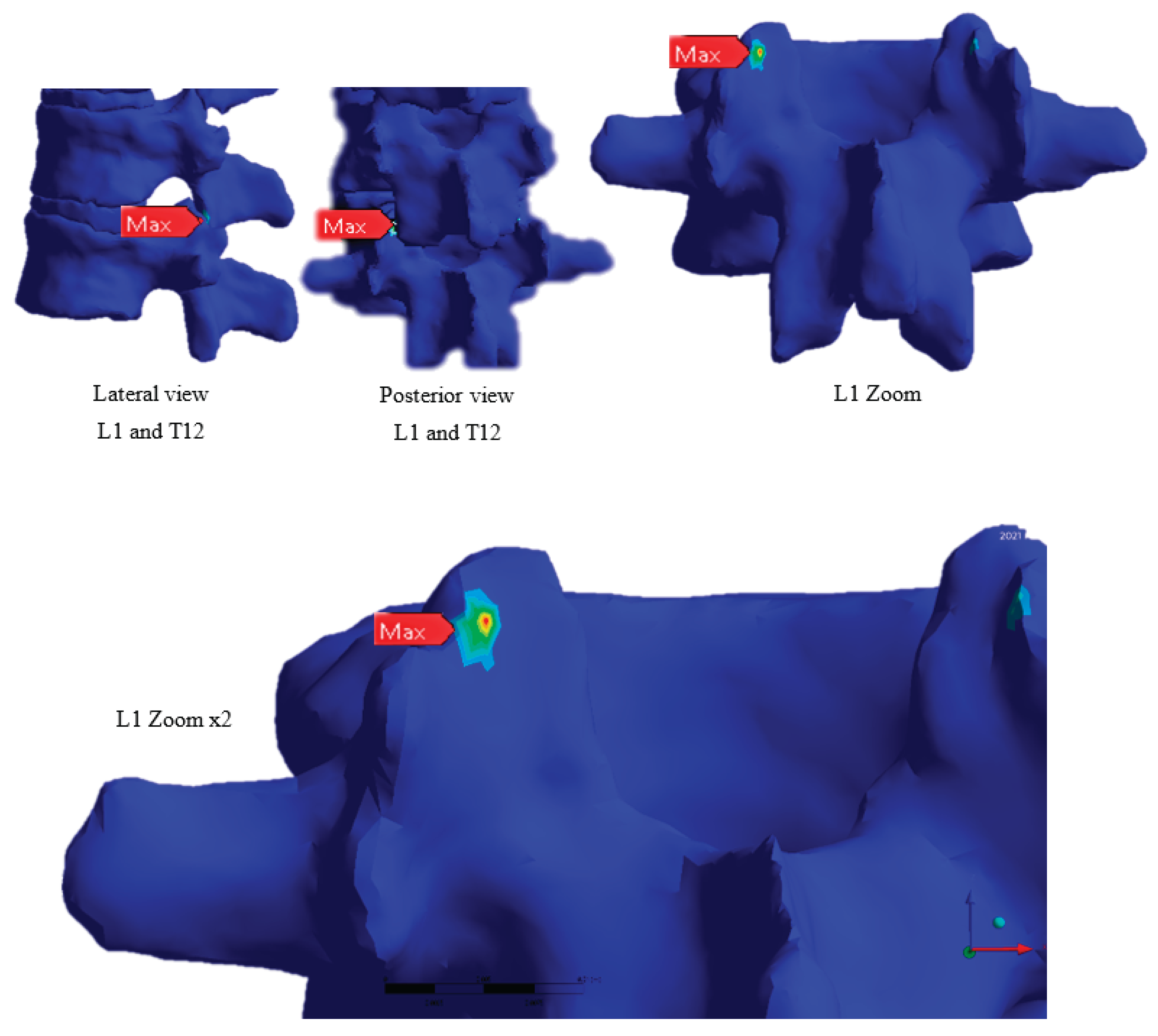
Figure 12.
Total Strain of the Vertebral Column from T11 to T12 Under 120 kg Load.
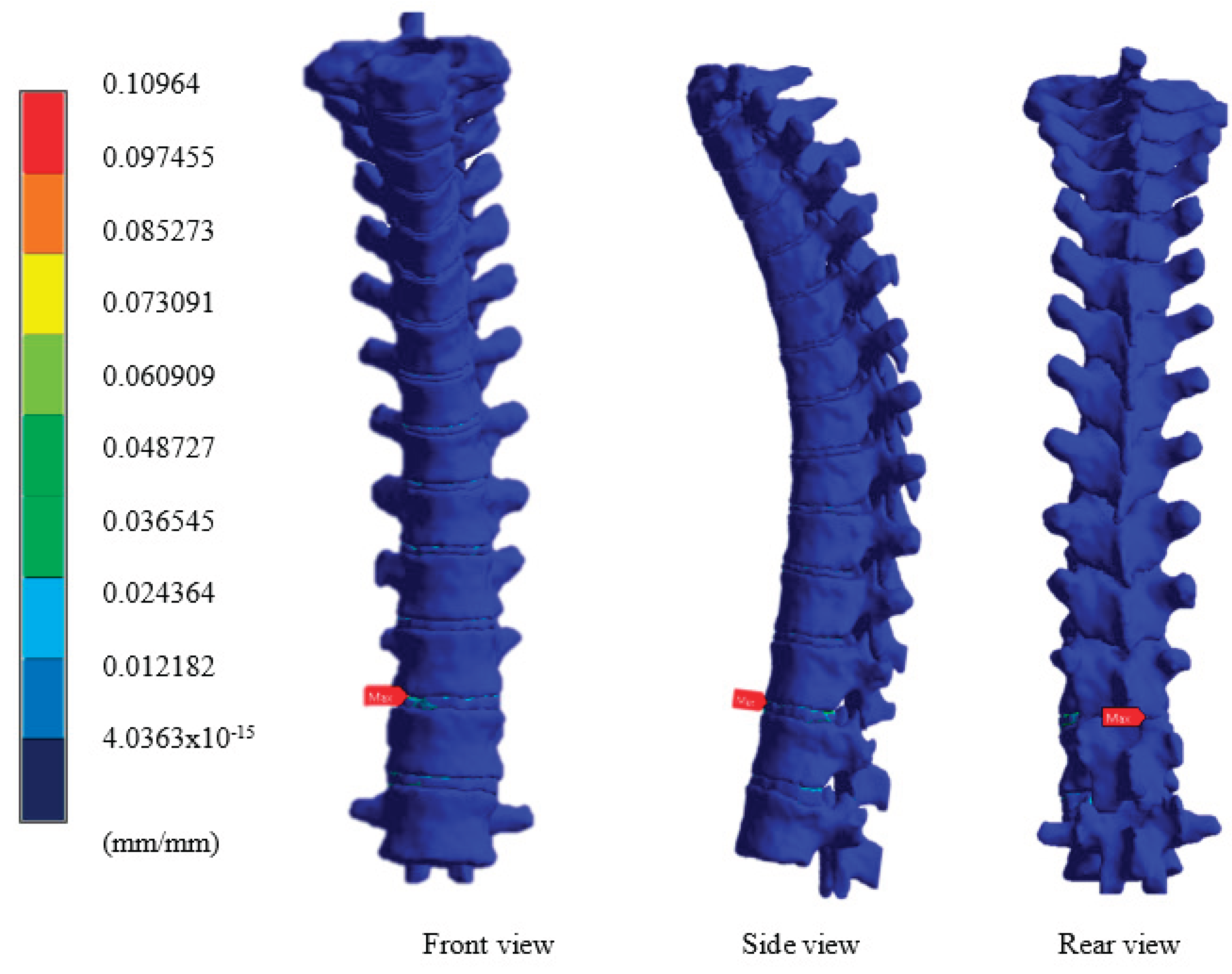
Figure 13.
Total Strain of Vertebrae T11, T12, and the Intervertebral Disc.
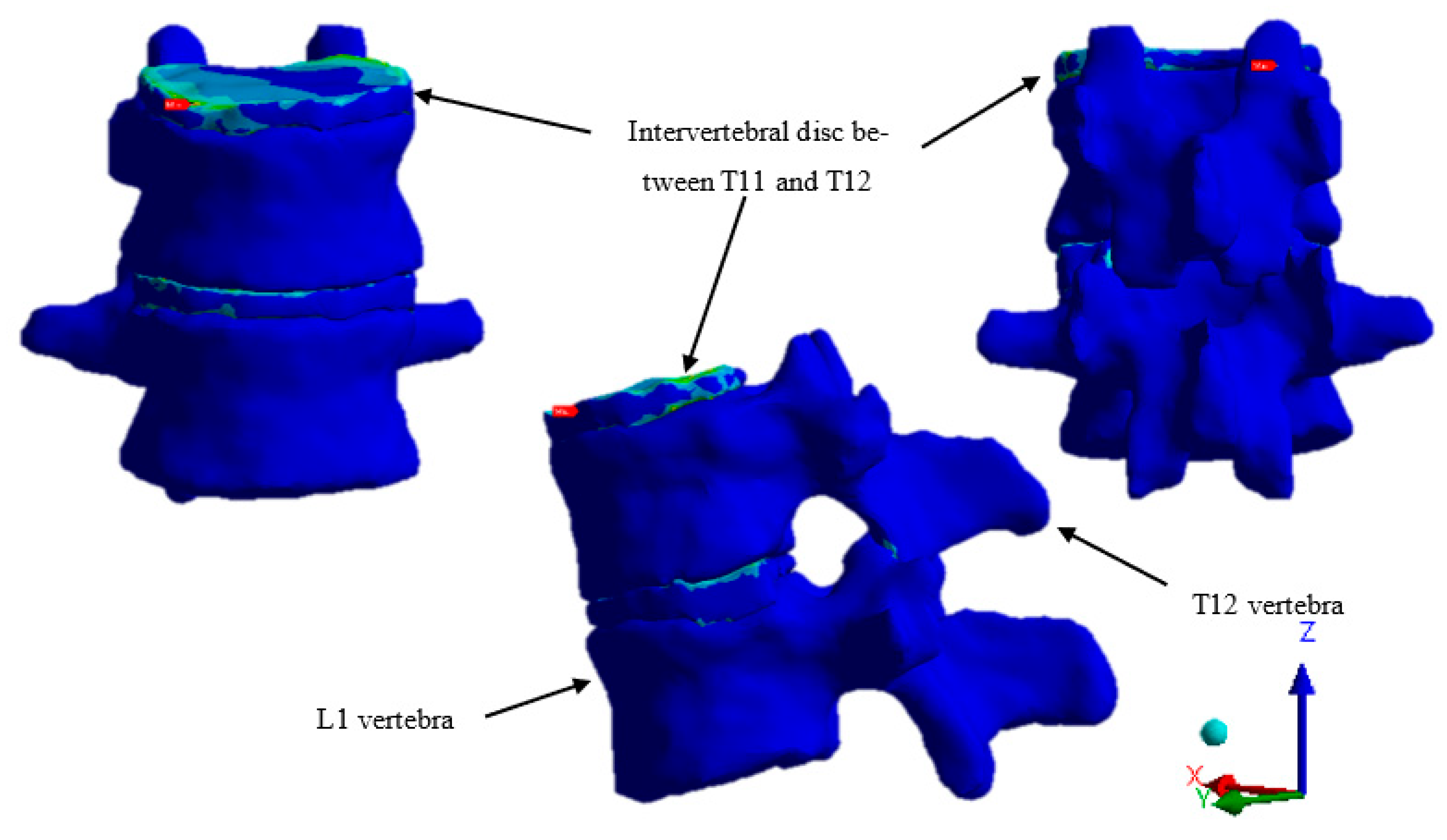
Figure 14.
Total Strain of the T11–T12 Intervertebral Disc Under 120 kg Load.
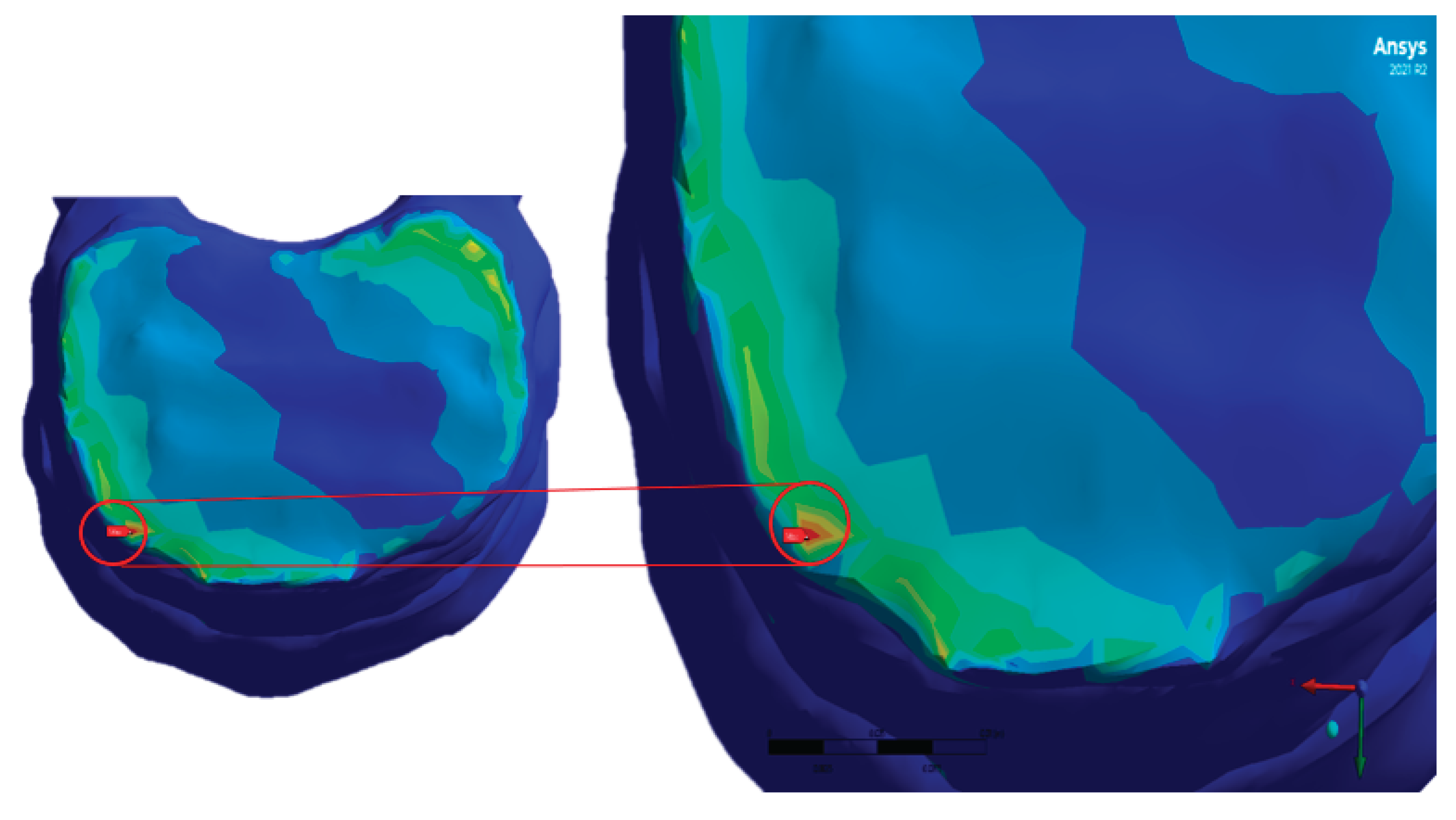
For a load of 600 N, corresponding to a moderate situation, the intervertebral discs showed controlled levels of deformation, mainly in the middle region (T6-T8), with Von Mises stresses within the physiological tolerance range [20]. However, when the load was increased to 900 N and subsequently to 1200 N, a significant increase in internal stresses was identified, particularly in the T7-T8 and T8-T9 discs, which presented stress concentrations exceeding 8 MPa, close to the elastic limit of fibrocartilaginous tissue, as reported in the literature [29]. Furthermore, the maximum deformations were concentrated in the posterior part of the annulus fibrosus of these discs, which coincides with the typical damage patterns observed in herniated discs, in which the nucleus pulposus tends to displace posteriorly due to axial compression [30]. Shear stresses were also higher in these discs, suggesting acumulative fatigue behaviour when exposed to repetitive loads. In some simulations, areas with stresses exceeding 10 MPa were observed in the posterior fibres of the T8-T9 disc, indicating a critical condition and supporting the hypothesis that this region may be susceptible to the development of a thoracic disc herniation under intense and repetitive loading scenarios. Results were obtained using colour spectra to display the von Mises stress, total displacement, and equivalent strain, allowing for a clear visualisation of the areas with the greatest structural vulnerability. These critical areas are aligned with the applied load axis; however, their exact location also depends on the mechanical behaviour of the adjacent trabecular bone, which was validated through comparative analyses between cross-sections of the model.
4. Discussion
The findings suggest that higher loading rates may increase the risk of intervertebral disc injury, aligning with previous studies highlighting the importance of loading in bone mechanics. Limitations of the study include the need for a larger number of simulations and the consideration of additional factors such as age and morphology. Results obtained through static structural analysis indicate that the thoracic spine, specifically the intervertebral discs located between T7 and T9, experiences significantly elevated levels of stress and strain when subjected to axial loads simulating the lifting of an Olympic barbell. These findings support the study's initial hypothesis. There is a high likelihood that this region could become a point of origin for thoracic disc herniation, especially under conditions of intense or poorly executed physical training. The mid-thoracic region has historically been less studied compared to the lumbar region due to its lower mobility, which may lead to a perceived lower clinical risk. However, the present analysis reveals that biomechanical interactions between axial load and the structural geometry of the thoracic vertebrae can generate stress concentrations in areas not typically considered high-risk. This finding is consistent with studies by Kazarian (1975), as mentioned in the text, and Nicholson (1997) [31], who noted that even the least mobile areas can experience significant structural damage under specific loads. Furthermore, the analysis demonstrated that as the applied load increases, the localised deformations in the posterior fibrous annulus of the intervertebral discs exceed the expected values of physiological deformation, approaching the damage threshold. This observation is consistent with that reported by [26], who related microfracture and cumulative damage in bone and fibrocartilaginous structures with the increase in the applied loading rate. It should be noted that, although the model used represents a healthy male spine, the inclusion of factors such as age, preexisting disc degeneration, accumulated mechanical fatigue, or poor postural technique could intensify the observed effects. Therefore, it is reasonable to assume that, in individuals with unfavourable conditions, the loads simulated here could trigger real injuries. Among the study's limitations are the simplification of the biomechanical properties of some soft tissues (such as paraspinal ligaments and muscles), as well as the use of a single anatomical case. Future simulations could benefit from a more detailed approach, utilising coupled musculoskeletal models and transient dynamic analysis, to more accurately represent real-life training situations.
5. Conclusions
This study offers an initial insight into the behaviour of intervertebral discs under load, identifying potential risk areas for disc herniation. Numerical simulations provide a valuable approach to evaluating spinal mechanics and informing future research. This study confirms, through numerical simulation in ANSYS Workbench, that intervertebral discs in the mid-thoracic region, particularly between T7 and T9, are susceptible to developing structural damage under intense axial loads such as those generated during weightlifting. Critical zones of stress and strain concentration were identified, which coincide with the typical mechanisms associated with the development of disc herniations. The results validate the initial hypothesis by demonstrating that the thoracic region, although historically considered less vulnerable than the lumbar region, can become a focus of disc injury when subjected to high loading conditions, especially if they are repeated over time or combined with individual factors such as disc degeneration, poor posture, or muscle misalignment.
Furthermore, this work reaffirms the value of computational simulation tools to support biomechanical research. The ability to model specific conditions without resorting to invasive methods or complex physical testing opens the door to personalised studies, with both clinical and preventive applications in sports. Future research recommends:
- Incorporating active muscle models and dynamic simulations to reflect real-life exercise conditions better.
- Evaluating clinical cases with preexisting disc degeneration to determine individual variations in structural behaviour.
- Considering factors such as age, sex, and lifting technique to generate more precise recommendations aimed at injury prevention.
Overall, this research contributes to the understanding of the biomechanical causes of thoracic disc herniation, an underexplored phenomenon, and proposes a replicable methodological approach for studying other regions of the spine or high-impact loading activities.
Acknowledgments
The authors would like to thank the National Council of Humanities, Sciences and Technologies (CONAHCYT) for its support in the development of this research. We also express our sincere gratitude to the Instituto Politécnico Nacional (IPN) for providing the academic and institutional framework that made this work possible.
References
- Andersson, G.B. Epidemiological features of chronic low-back pain. Lancet 1999, 354, 581–585, . [CrossRef]
- Jordan, J.; Konstantinou, K. y O'Dowd, J., Herniated lumbar disc, BMJ Clinical Evidence, Vol. 1118, pp 1-65, 2009.
- Reinhar L. V., Müller-Gerbl M., The vertebral Column A phylogenetic failure? A Theory explaining the function and vulnerability of the human spine, Clinical Anatomy, Vol. 9 no.3, pp 143-213, 1996.
- Ruiz-Santiago, F., Castellano-García, M., Guzmán-Álvarez, L., Tello-Moreno, M. Computed tomography and magnetic resonance imaging in painful diseases of the spine; Respective contributions and controversies. Radiology, Vol. 53, pp 116–133, 2011.
- Micheli. F., Tratado de neurología clínica, Médica Panamericana, pp 185-195, 2002.
- Lohfeld, S., Barron, V., McHugh, P.E. Biomodels of Bone: A Review. Annals Biomedical Engineering, Vol 33, pp 1295–1311, 2005.
- Kazarian, L.E. Creep Characteristics of the Human Spinal Column. Orthop. Clin. North Am. 1975, 6, 3–18, . [CrossRef]
- Zioupos, P.; Hansen, U.; Currey, J.D. Microcracking damage and the fracture process in relation to strain rate in human cortical bone tensile failure. J. Biomech. 2008, 41, 2932–2939, . [CrossRef]
- Albert, D.L.; Katzenberger, M.J.; Hunter, R.L.; Agnew, A.M.; Kemper, A.R. Effects of loading rate, age, and morphology on the material properties of human rib trabecular bone. J. Biomech. 2023, 156, 111670, . [CrossRef]
- Nicholson, P.; Cheng, X.; Lowet, G.; Boonen, S.; Davie, M.; Dequeker, J.; Van der Perre, G. Structural and material mechanical properties of human vertebral cancellous bone. Med Eng. Phys. 1997, 19, 729–737, . [CrossRef]
- El Bojairami, I.; El-Monajjed, K.; Driscoll, M. Development and validation of a timely and representative finite element human spine model for biomechanical simulations. Sci. Rep. 2020, 10, 1–15, . [CrossRef]
- Ayala-Lozano, J. F., Urriolagoitia-Sosa, G., Romero-Angeles, B., Torres-San Miguel, C. R., Aguilar-Pérez, L. A. y Urriolagoitia-Calderón, G. M., Diseño mecánico de un exoesqueleto para rehabilitación de miembro superior, Revista Colombiana de biotecnología, No.17 vol.1, pp 79-90. 2015.
- Martinez-Mondragon, M.; Urriolagoitia-Sosa, G.; Romero-Ángeles, B.; García-Laguna, M.A.; Laguna-Canales, A.S.; Pérez-Partida, J.C.; Mireles-Hernández, J.; Carrasco-Hernández, F.; Urriolagoitia-Calderón, G.M. Biomechanical Fatigue Behavior of a Dental Implant Due to Chewing Forces: A Finite Element Analysis. Materials 2024, 17, 1669, . [CrossRef]
- A Wesolowski, S.; Golaski, W.M.; Sauvage, L.R.; McMahon, J.D.; Komoto, Y. Considerations in the development of small artery prostheses.. 1968, 14, 43–7.
- Solano, P. A., Sánchez-Quintero, D., Santrich, M. y Montoya-Cobo, E., Revisión anatomofuncional de las articulaciones de la columna vertebral y la caja torácica. Salutem Scientia Spiritus, No.8 vol. 4, pp 39-45, 2022.
- Andreas Gradischara, Carola Lebschya, Wolfgang Kracha, Marcell Krallb, Melanie Fediukb, Anja Gieringerb, Freyja Smolle-Jüttnerb, Niels Hammerc,d,e, Benoît Beyerf, Josef Smolleg, Ute Schäferh, Measurement of global mechanical properties of human thorax Costal cartilage, Journal of Biomechanics, No. 142, pp 1-9, 2022.
- Kim, E.S. Accident Reconstruction of Damaged Human Body Using MDCT and Computer Numerical Analysis. Appl. Sci. 2020, 10, 3059, . [CrossRef]
- Öhman-Mägi, C.; Holub, O.; Wu, D.; Hall, R.M.; Persson, C. Density and mechanical properties of vertebral trabecular bone—A review. JOR Spine 2021, 4, e1176, . [CrossRef]
- Marini, G.; Ferguson, S.J. Nonlinear numerical analysis of the structural response of the intervertebral disc to impact loading. Comput. Methods Biomech. Biomed. Eng. 2012, 17, 1002–1011, . [CrossRef]
- Li, H.; Wang, Z. Intervertebral disc biomechanical analysis using the finite element modeling based on medical images. Comput. Med Imaging Graph. 2006, 30, 363–370, . [CrossRef]
- Shirazi-Adl, A.; Ahmed, A.; Shrivastava, S. A finite element study of a lumbar motion segment subjected to pure sagittal plane moments. J. Biomech. 1986, 19, 331–350, . [CrossRef]
- Sun, Z.; Mi, C. Biomechanics of annulus fibrosus: Elastic fiber simplification and degenerative impact on damage initiation and propagation. J. Mech. Behav. Biomed. Mater. 2024, 157, 106628, . [CrossRef]
- Pohlan, J.; Stelbrink, C.; Pumberger, M.; Deppe, D.; Schömig, F.; Hecht, N.; Göhler, F.; Hamm, B.; Diekhoff, T. Age-dependent microstructural changes of the intervertebral disc: a validation of proteoglycan-sensitive spectral CT. Eur. Radiol. 2021, 31, 9390–9398, . [CrossRef]
- I, R.A.S.; V, C.C.; Goplani, P. Fracture strength estimation of L3-L4 intervertebral disc using FEA. Vibroengineering PROCEDIA 2019, 27, 67–72, . [CrossRef]
- Zhang, G.; Chen, X.; Ohgi, J.; Jiang, F.; Sugiura, S.; Hisada, T. Effect of intercostal muscle contraction on rib motion in humans studied by finite element analysis. J. Appl. Physiol. 2018, 125, 1165–1170, . [CrossRef]
- Stone, M.H.; Fry, A.C.; Ritchie, M.; Stoessel-Ross, L.; Marsit, J.L. Injury Potential and Safety Aspects of Weightlifting Movements. Strength Cond. J. 1994, 16, . [CrossRef]
- Al-Hammadi, A.S.S.; Saidin, S.; Ramlee, M.H. Simulation Analyses Related to Human Bone Scaffold: Utilisation of Solidworks® Software in 3D Modelling and Mechanical Simulation Analyses. J. Hum. Centered Technol. 2022, 1, 97–104, . [CrossRef]
- Ferracutti, R.; Czerniecki, A.; Paloto, J.; Molinari, N. Análisis de las Causas de Hernia de Disco Intervertebral. 2004, 15, 43–48, . [CrossRef]
- Virgin, W.J. Experimental investigations into the physical properties of the intervertebral disc. J. Bone Jt. Surgery. Br. Vol. 1951, 33-B, 607–611, . [CrossRef]
- Kadow, T.; Sowa, G.; Vo, N.; Kang, J.D. Molecular Basis of Intervertebral Disc Degeneration and Herniations: What Are the Important Translational Questions? Clin. Orthop. Relat. Res. 2015, 473, 1903–1912, . [CrossRef]
- Nicholson, P.; Cheng, X.; Lowet, G.; Boonen, S.; Davie, M.; Dequeker, J.; Van der Perre, G. Structural and material mechanical properties of human vertebral cancellous bone. Med Eng. Phys. 1997, 19, 729–737, . [CrossRef]
- Yoganandan, N., Ray, G., Pintar, F. A., Myklebust, J. B. y Sances Jr, A., Stiffness and strain energy criteria to evaluate the threshold of injury to an intervertebral joint, Journal of biomechanics, No. 22 Vol. 2, 135-142, 1989.
Figure 1.
Possible Effect of Carrying Too Much Weight.
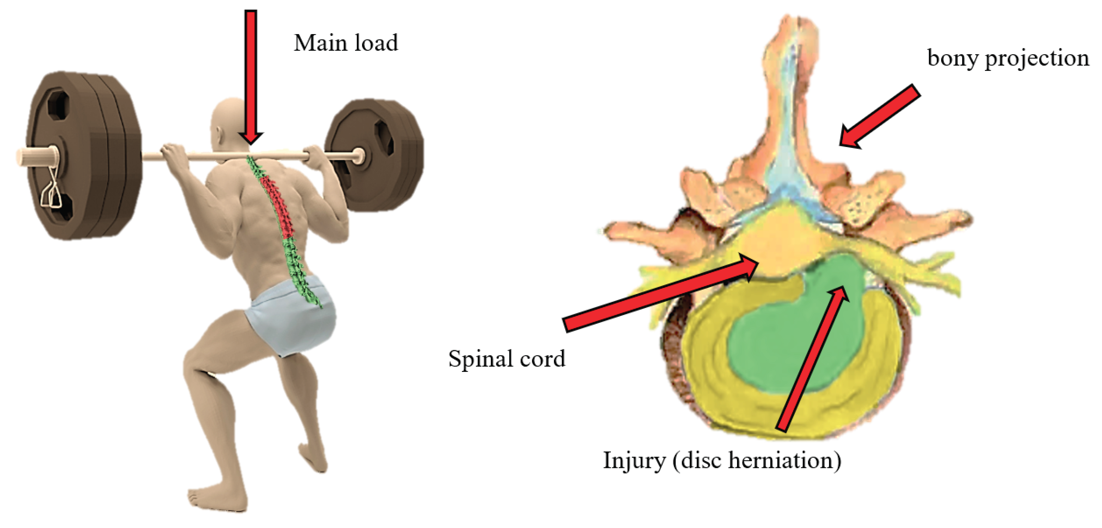
Figure 2.
Movement of Vertebrae in the Spine.
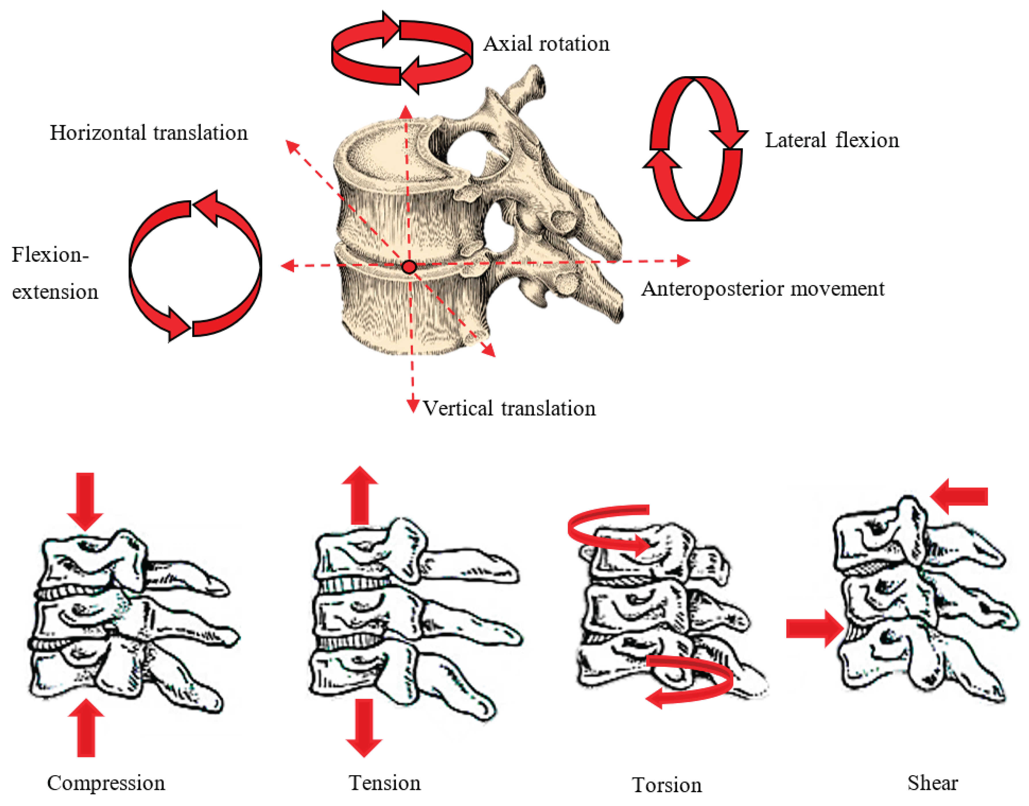
Figure 3.
Stages of Disc Herniation.
Disclaimer/Publisher’s Note: The statements, opinions and data contained in all publications are solely those of the individual author(s) and contributor(s) and not of MDPI and/or the editor(s). MDPI and/or the editor(s) disclaim responsibility for any injury to people or property resulting from any ideas, methods, instructions or products referred to in the content. |
© 2025 by the authors. Licensee MDPI, Basel, Switzerland. This article is an open access article distributed under the terms and conditions of the Creative Commons Attribution (CC BY) license (http://creativecommons.org/licenses/by/4.0/).
Copyright: This open access article is published under a Creative Commons CC BY 4.0 license, which permit the free download, distribution, and reuse, provided that the author and preprint are cited in any reuse.


