Submitted:
31 July 2025
Posted:
01 August 2025
You are already at the latest version
Abstract
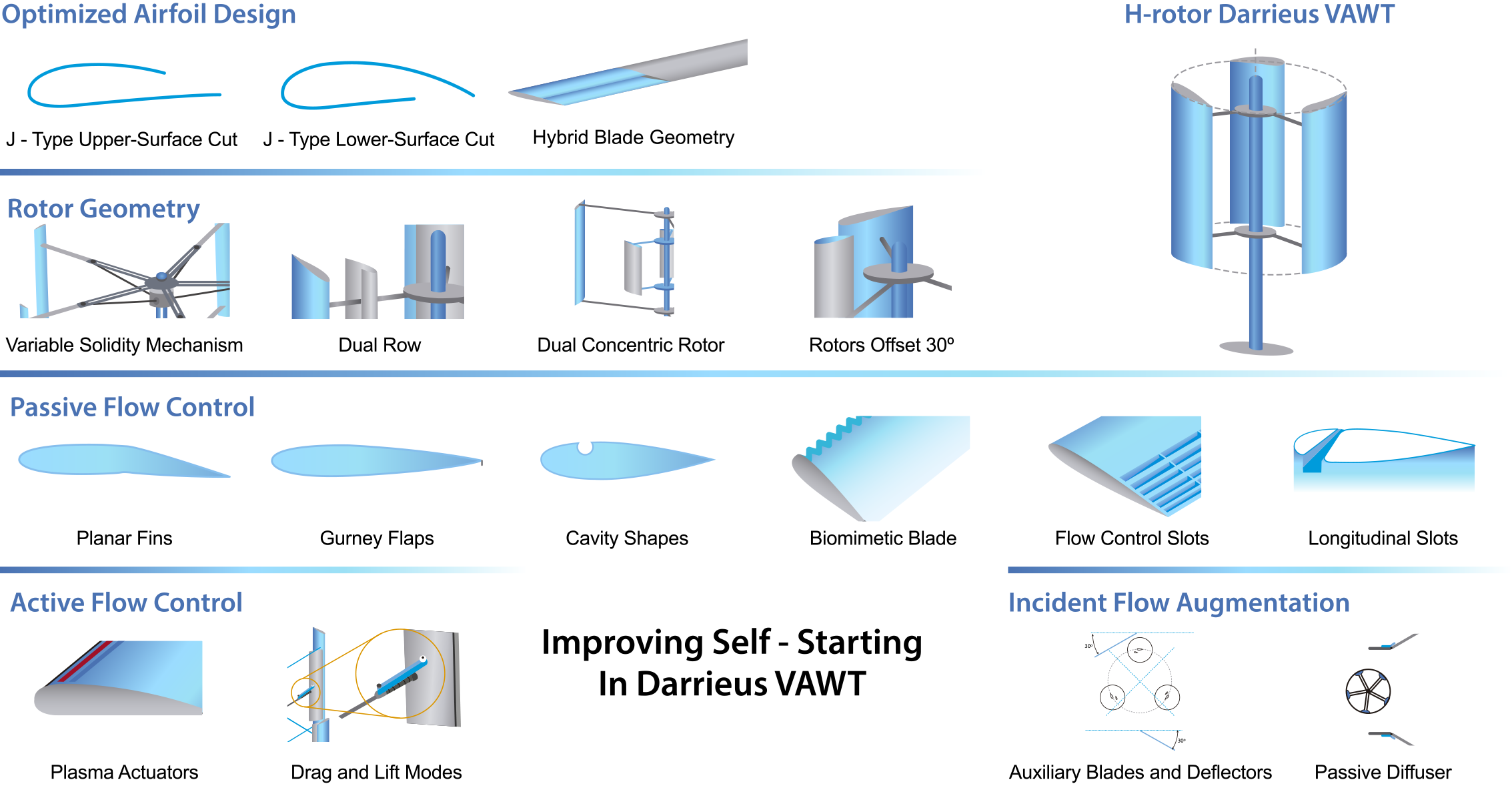
The self-starting capability of straight-bladed Darrieus vertical axis wind turbines (VAWTs) remain a major constraint for their widespread deployment, particularly in urban environments with highly variable wind conditions. This article presents an in-depth review of technological strategies aimed at enhancing the self-starting performance of Darrieus VAWTs, classified into five key categories: (1) aerodynamic blade profile design, (2) rotor structural configuration, (3) passive flow control, (4) active flow control, and (5) incident flow augmentation. Multiple approaches are analyzed, highlighting design parameters, operating conditions, and performance metrics, with a focus on torque coefficient and power coefficient during the startup phase. Findings suggest that hybrid strategies can substantially enhance initial torque generation, such as combining optimized profiles with control mechanisms. Nevertheless, critical challenges remain, including limited experimental validation, insufficient use of 3D simulations coupled with structural models, and a lack of comprehensive assessments regarding technical and economic feasibility. A future research agenda is proposed, emphasizing the integration of artificial intelligence, additive manufacturing, and real-world testing for the development of more autonomous, efficient, and urban-adaptable wind turbines.
Keywords:
Darrieus VAWT
; self-starting
; turbine optimization
; urban wind energy
1. Introduction
Growing concerns about climate change, environmental degradation, and the depletion of natural resources have led to a global imperative to reduce dependence on fossil fuels for energy generation. This challenge has been further intensified by rapid population growth and the resulting increase in energy demand, which have exacerbated the environmental impacts associated with intensive fossil fuel use [1].
In this context, renewable energy sources have become a central pillar in the transition toward more sustainable energy systems. Among these, wind energy has emerged as one of the most promising alternatives, thanks to its technical viability and its potential to significantly reduce greenhouse gas emissions. According to the International Energy Agency [2], the power sector emitted 13 gigatons of carbon dioxide in 2021, more than one-third of global energy-related emissions. To meet global climate targets by 2030, renewable capacity must triple, with wind and photovoltaic solar energy leading this growth.
The International Electrotechnical Commission [3] emphasizes that expanding renewable energy not only helps mitigate climate change, but also supports rising energy demand, particularly in developing regions. In this regard, vertical axis wind turbines (VAWTs) have gained renewed attention for small-scale and urban applications due to their ability to capture wind from any direction and operate more reliably in turbulent environments [4,5].
Among VAWT configurations, the H-type Darrieus turbine stands out for its compact design and structural simplicity, making it suitable for residential or distributed generation scenarios. While their nominal power is typically low due to size constraints, large-scale deployment of these turbines could significantly contribute to renewable electricity generation. However, one major limitation remains: their poor self-starting capability, primarily due to insufficient starting torque at low Tip Speed Ratios (TSR) [4,6,7].
This problem has been extensively documented in the literature, prompting the development of various strategies aimed at improving startup performance through aerodynamic blade redesign. Common approaches include asymmetric profiles, modified geometries, hybrid Savonius-Darrieus rotors, and both passive and active pitch control mechanisms [8,9]. Many of these solutions involve a trade-off between improved self-starting and reduced steady-state efficiency, typically reflected in a lower Power Coefficient (CP) at high TSR values [4].
Given the diversity of existing approaches and the absence of a comprehensive review that integrates their principles and results, this article aims to critically analyze the state of the art in blade design strategies to enhance the self-starting performance of H-type Darrieus VAWT. The goal is to classify key aerodynamic strategies, compare their technical effectiveness, and discuss their benefits, limitations, and future research directions.
The remainder of this paper is organized as follows: Section 2 presents the aerodynamic and operational background of Darrieus-type VAWTs, highlighting their self-starting limitations. Section 3 provides a comprehensive review of five strategic approaches aimed at enhancing self-starting capability. Section 4 offers a critical discussion comparing the strengths, weaknesses, and feasibility of each strategy. Section 5 identifies current research gaps and outlines future directions, including emerging technologies. Finally, Section 6 presents the main conclusions of the study.
2. Technical Fundamentals of Self-Starting in Darrieus-Type Wind Turbines
Wind turbines are commonly classified into two categories based on the orientation of their rotational axis: horizontal-axis wind turbines (HAWTs) and VAWTs [10]. HAWTs feature a horizontal axis parallel to the ground and operate in either upwind or downwind configurations [11]. In contrast, VAWTs are further subdivided according to the dominant aerodynamic force acting on their blades: drag-driven designs, such as the Savonius rotor, and lift-driven designs, with the Darrieus rotor being the primary representative. The latter can be categorized into three main variants based on blade geometry: eggbeater (curved-blade), helical, and H-type with straight blades [12]. Figure 1 illustrates the main VAWT configurations, highlighting their distinct geometric characteristics.
The H-type Darrieus VAWT employs straight blades arranged parallel to the rotational axis, connected to a central shaft through radial arms. This geometric layout provides an efficient structural solution that maintains a consistent lift path throughout the rotor’s revolution. Compared to other variants such as the helical or eggbeater designs, the H-type exhibits a simpler aerodynamic behavior that is more straightforward to model, albeit extremely sensitive to incoming flow conditions. In this type of turbine, blade design, including airfoil profile, angle of attack, and angular positioning, plays a critical role in aerodynamic torque generation [5]. Therefore, understanding the operating principles and aerodynamic interactions associated with this configuration is essential for optimizing overall performance, particularly during transitional phases such as startup.
2.1. Evolution of the Self-Starting Concept and Torque Generation in Darrieus-Type Turbines
VAWT of the Darrieus type in the “H” configuration operate based on a lift-driven principle. When wind flows over the blade, a lift force (FL) is generated perpendicular to the relative airflow. This force arises from the pressure difference between the upper and lower surfaces of the airfoil. If the angle of attack is appropriate, a component of this force aligns with the direction of rotor rotation, producing the torque needed to drive the system. Simultaneously, a Drag Force (FD) acts parallel to the airflow and opposes the blade’s motion, resulting from friction and pressure differences [13]. Figure 2 presents a schematic representation of the lift and drag forces acting on the blades to generate the aerodynamic torque that drives the system.
At low wind speeds, such as those present during startup from rest, the blades rapidly traverse regions of the rotation cycle where the angle of attack changes abruptly, making it difficult to consistently generate favorable lift forces. As a result, the aerodynamic torque is often insufficient to overcome the system’s inertia, preventing the rotor from accelerating in a sustained manner. The pitching moment induced by these aerodynamic forces affects the angular stability of the blade, especially during transient phases [11]. The self-starting phenomenon in H-type Darrieus turbines is closely linked to how aerodynamic torque is generated in the early stages of rotation. Consequently, the design of the blade profile and its interaction with the incoming flow play a critical role in the turbine’s ability to start without external assistance. This challenge has motivated extensive efforts to understand and redefine the self-starting concept from both experimental and theoretical perspectives.
Over time, various studies have sought to more precisely define the self-starting behavior in this type of turbine. In the context of HAWTs, Ebert and Wood [14] defined startup as complete when the turbine begins to extract significant power from the wind. This definition was later adapted for VAWTs by Kirke [15], who proposed that a turbine is considered self-starting if it can accelerate from rest to the point of producing useful power without the need for external assistance.
Hill et al. [16] experimentally analyzed the startup of a three-bladed Darrieus turbine (NACA0018 profile) in a wind tunnel at 6.0 m/s, identifying four distinct phases: (1) initial acceleration, (2) dead band, (3) final acceleration, and (4) steady operation. This sequence was later confirmed by Sun et al. [17], who evaluated H-type turbines with NACA0018 and NACA4418 profiles under both laminar and turbulent flow conditions. The dead band, also referred to as the plateau phase, is characterized by near-zero or even negative net torque, making it difficult for the rotor to continue accelerating. However, experimental and field observations have shown that, in some cases, the turbine can traverse this region without external intervention [18]. Figure 3 presents the startup process of a Darrieus-type wind turbine, highlighting the four identified phases.
Worasinchai et al. [19] challenged the “significant power” criterion due to its dependence on the load connected to the system, arguing that it lacks precision. Instead, they proposed a more robust definition: a turbine should be considered self-starting only if it can accelerate from rest to a TSR at which continuous aerodynamic thrust is generated along the blade’s path, allowing it to overcome resistive torque and reach a stable operating regime.
This view was supported by Du [20], who emphasized that startup should be considered successful only if the turbine reaches its optimal operating condition without any mechanical or electrical assistance. In line with this perspective, Celik [21] defined self-starting as the process by which a turbine accelerates from rest to a TSR high enough to sustain stable operation.
More recently, Selvarajoo and Mohamed [22] investigated the effects of dynamic stalls on the startup of a three-bladed Darrieus turbine using NACA0012 profiles. Through simulations with QBlade and a custom MATLAB module named DRAFA (Darrieus Rotor Aerodynamic Force Analysis), they visualized aerodynamic forces and flow trajectories. Their results showed that, during the dead band phase, reverse dynamic stall events occur, producing a negative average torque. An effective startup begins when dynamic stalls emerge, enabling sustained rotor acceleration. These findings highlight the critical role of dynamic flow behavior in turbine startup performance and underscore the importance of aerodynamic insight for designing self-starting blades.
2.2. Critical Parameters for the Characterization of Aerodynamic Performance
The aerodynamic behavior of an H-type Darrieus turbine is strongly influenced by dimensionless parameters that enable the evaluation of its performance under both steady-state and transient conditions. These parameters allow for standardized comparisons between different designs and help predict the system’s behavior in response to airflow conditions.
The FL and FD, generated by the interaction between the airflow and the aerodynamic profile, are used to define the dimensionless coefficients CL and CD, as described by Zhu et al. [23]. These are critical parameters for characterizing aerodynamic performance.
where (ρ) is the air density, (c) is the chord length, and (Vrel) is the relative velocity of the incoming flow.
Additionally, Zhu et al. [23] emphasized the importance of the CM and the CP for characterizing the overall performance of the system, given by:
where (A) is the swept area of the rotor, and (V∞) is the free-stream wind velocity. () refers to the average torque over a full revolution, and (P) is the generated power, calculated as:
where (ω) is the angular velocity of the turbine rotor in rad/s. According to Burton et al. [24], the CP is used to estimate the efficiency of a wind turbine by relating the mechanical power extracted to the available kinetic power of the wind.
The tangential force (FT) and normal force (FN) acting on the blade also give rise to dimensionless coefficients CT and CN, respectively [23]:
Another essential parameter is the Reynolds number (Re), which relates inertial forces to viscous forces in the flow and determines the aerodynamic regime (laminar or turbulent) [11]:
where (D) is the rotor diameter and (μ) is the dynamic viscosity, which is related to the kinematic viscosity (ν) by:
In the case of a rotating blade, the Reynolds number can also be estimated using the blade’s linear velocity (Vb) and the chord length (c):
TSR (λ) is one of the most critical parameters as it directly affects energy extraction efficiency [25]. It is defined as the ratio between the blade tip speed and the free-stream wind velocity [26]:
(Nrpm) is the angular velocity in revolutions per minute (rpm), and (R) is the rotor radius. Alternatively, it can be expressed in terms of the CP and CM [24]:
Figure 4 illustrates the velocity triangle and the main forces acting on the blade, facilitating the understanding of the aerodynamic analysis.
2.3. Specific Self-Starting Challenges
Improving self-starting capability and reducing the time required to initiate rotation are critical for Darrieus-type VAWTs, especially in regions with low wind speeds [27]. A major limitation of these turbines lies in their low aerodynamic torque generation at low TSR, which can occasionally result in negative net torque, preventing the rotor from overcoming its initial inertia [28].
This behavior is intensified in the so-called dead zone, a phase during which the net torque is nearly zero or negative, hindering the transition to sustained acceleration. Overcoming this region without external assistance strongly depends on rotor geometry and optimized design parameters [17,20]. Figure 5 illustrates some of the geometric parameters relevant to H-type Darrieus turbines, such as rotor diameter (D), blade height (H), chord length (c), and swept area (A).
Solidity (σ), defined as the ratio between the total blade area and the swept rotor area, directly influences startup torque. High solidity increases the initial torque but reduces the maximum Cₚ, shifting its optimal value to lower TSRs [29,30]. Conversely, low-solidity turbines are more aerodynamically efficient but less capable of self-starting at low TSR values. The number of blades (N) also affects startup stability; turbines with three blades have demonstrated effective self-starting performance when appropriately designed [20,31].
The airfoil shape of the blades is also critical. Classic symmetrical NACA airfoils (e.g., NACA0012, NACA0018) have been widely used, but recent designs focus on improved aerodynamic performance under non-ideal conditions. These include natural laminar flow airfoils, thick symmetrical profiles, and biomimetic modifications such as sinusoidal tubercles on the leading edge— inspired by humpback whale fins [32,33].
The angle of attack (α) varies cyclically as the rotor spins, impacting lift generation and consequently torque output. Poor control over this angle can induce dynamic stall, compromising startup performance. Blade pitch angle (β) control can mitigate these effects by maintaining an optimal angle of attack across azimuthal positions [13,21,34].
Under low wind conditions, the rotor’s moment of inertia (J) and the resistive torques (TResist) become dominant. These include: the frictional torque (TF), which depends on the condition of the bearings and the material and surface roughness of the blades; the inertial torque (TJ), determined by the blade’s mass and radius; and the aerodynamic drag torque (TD), which is influenced by the drag coefficient (CD). To achieve effective startup, all of these must be overcome by the aerodynamic torque (TA) generated by lift forces. The balance among these torques defines the self-starting capability of the system [21,26]:
Minimizing (TResist) and maximizing (TA) through refined blade design and material selection is essential to ensuring reliable autonomous startups.
3. Technological Approaches for Enhancing the Self-Starting Capability of H-Type VAWT’s
This section presents a structured review of the main strategies proposed in the literature to improve the self-starting capability of straight-bladed Darrieus-type VAWTs. To this end, a systematic search was conducted in scientific databases such as Scopus, IEEE Xplore, Web of Science, and ScienceDirect. The following search string was used:
(“improvement” OR “performance”) AND (“cut-in speed” OR “self-start” OR “self-starting” OR “low wind speed”) AND (“Darrieus-H” OR “vertical axis” OR “VAWT”) AND (“airfoil” OR “shape J” OR “flap Gurney”) AND PUBYEAR > 2018 AND PUBYEAR < 2026 AND (LIMIT-TO (LANGUAGE, “English”)) AND (LIMIT-TO (DOCTYPE, “ar”))
The selection focused on studies specifically addressing improvements to the starting performance of Darrieus-type “H” VAWTs. This analysis revealed several recurring technological approaches, which are explored and discussed in detail in the following subsections according to their specific focus and implementation strategy.
3.1. Geometrical Optimization of the Airfoil
This strategy includes studies focused on the design and analysis of novel aerodynamic profiles; one of the most promising proposals has been the use of “J”-type blades. This profile is derived from modifications to conventional “S”-type airfoils by partially removing a section of the upper or lower surface, resulting in an asymmetric shape that enhances vortex formation in specific regions of the blade. The “J” and “S” airfoil types are shown in Figure 6, where their key geometric differences are visually compared.
Several studies have explored the effectiveness of this modified geometry. Farzadi et al. [35] analyzed J-shaped blades derived from the NACA0021 profile using 3D CFD simulations (URANS with k-ω SST and k-ε turbulence models), evaluating their behavior under various TSRs and blade heights. Their results indicate that dynamic stall vortices dominate the mid-span region of the blade, and as the blade height increases, these vortices shift toward the blade tips, extending stagnation regions that contribute positively to torque generation. At TSR = 1.0, an increase in CM of 10% was observed for a height of 0.8 m, and up to 44% for a height of 3.0 m. Figure 7 shows the three-dimensional vortex distribution along the surface of the J-type blade, highlighting how its geometry enhances torque generation.
Naik and Sahoo [28] conducted a combined experimental and numerical investigation on curved J-type airfoils derived from the NACA4418 profile, generated by removing sections near the trailing edge. Their findings revealed that an airfoil with a 70% opening ratio enhanced the turbine’s efficiency by approximately 25% and significantly improved the self-starting torque. In earlier work, Naik and Sahoo [36] modified the NACA4415 profile by trimming portions of either the upper or lower surface, producing J-type variants with different opening ratios. Two-dimensional CFD simulations showed that airfoils with opening ratios ranging from 40% to 80% achieved CP between 0.488 and 0.517, values consistently higher than those of the original NACA4415. Additionally, upper-surface cuts yielded better aerodynamic performance compared to lower-surface modifications. Figure 8 illustrates the three airfoil configurations examined: the baseline NACA4415, a J-type profile with an upper-surface cut, and another with a lower-surface cut, offering a clear geometric comparison of the structural alterations introduced.
Farzadi and Bazargan [37] conducted 3D CFD simulations to analyze vortex interactions induced by the “J”-shaped geometry under various wind conditions, using blades derived from the NACA0021 profile. Their findings revealed that at low TSRs, the “J”-type blades increased the average torque by 37.5% at a wind speed of 5.0 m/s and by 26.9% at 10.0 m/s. However, at higher TSRs, a reduction in torque of up to 10% was observed, attributed to vortex shedding from the blade tips. Bel Laveda et al. [38] aerodynamically evaluated a three-bladed VAWT (blade length = 3.0 m, “J”-type NACA0015 profile, chord = 0.4 m, fixed angle of attack) using CFD simulations based on URANS turbulence models (k-ω SST and k-ε), along with structural analysis via finite element modeling. Their results showed an improvement in the CM of 18.34% with the k-ω SST model and 5.84% with the k-ε model, compared to the straight NACA0015 blade.
Maalouly et al. [39] used CFD combined with the Taguchi method to evaluate NACA 0012, 0015, 0017, and 0021 airfoils, varying the chord length between 0.2 and 0.8 m and the angle of attack at 0°, 2°, and 4°. The results revealed that chord length is the most critical parameter: longer chords favor self-starting capability, while shorter chords enhance steady-state performance. The optimal configuration was achieved with a NACA0017 airfoil, a 0.6 m chord length, and a 4° angle of attack, providing the best trade-off between starting capability and operational efficiency.
Celik et al. [40] proposed a series of J-shaped airfoils with opening ratios (OR) ranging from 0% to 90%, applied to a vertical-axis wind turbine with a diameter of 0.75 m and three blades based on various baseline profiles (NACA0012, 0018, 2518, and 4518, in both standard and inverted configurations). Each blade had a chord length of 0.083 m and a moment of inertia of 0.3 kg·m², operating under TSR between 1.5 and 3.0. They performed 2D CFD simulations using the SIMPLE method to evaluate dynamic self-starting behavior, emphasizing that this capability cannot be inferred solely from the CP or static CM. Their results indicate that larger opening ratios significantly improve self-starting performance, although an OR of 90% reduces efficiency at higher TSR values. They also found that a slight pitch angle (β) of 2° enhances startup, while an OR of only 10% is insufficient to overcome static inertia. Figure 9 depicts the various geometric cut configurations used to generate the J-shaped profiles, clearly illustrating how the opening ratio influences aerodynamic form.
Finally, Celik et al. [41] designed a hybrid blade by combining a NACA0018 airfoil in the central section with “J”-type tips featuring a 40% OR. Both 2D and 3D CFD simulations revealed significant improvements in self-starting capability and high-TSR performance. Among the six evaluated configurations, this combination exhibited the best aerodynamic behavior. Figure 10 illustrates the proposed hybrid blade geometry, highlighting the distribution of the conventional and modified segments.
Table 1 summarizes the main findings from these studies within the aerodynamic design strategy aimed at enhancing the self-starting capability of the Darrieus-type VAWT.
3.2. Configuration Strategies for H-Type VAWTS
One of the most effective strategies to enhance the self-starting capability of vertical Darrieus wind turbines lies in the geometric configuration of the rotor. Sun et al. [17] conducted a comparative study in a closed-loop wind tunnel to evaluate the aerodynamic power performance and self-starting behavior of H-type three-bladed Darrieus turbines and helical-bladed VAWTs under controlled turbulence levels (0%, 6.7%, and 11.9%). The study employed NACA0018 and NACA4418 airfoils with pitch angles of 0°, –3°, and –6°, analyzing CP, CM, TSR, and startup time. Results showed that while helical turbines operated over a wider TSR range, H-type turbines required 25% to 53% less startup time. The NACA0018 profile yielded higher aerodynamic efficiency but lower self-starting ability, whereas the NACA4418 profile improved startup performance under turbulent conditions at the cost of a reduced CP. Additionally, a moderate negative pitch angle (β = –3°) did not significantly improve performance compared to a neutral setting (β = 0°), and a more negative angle (β = –6°) led to a considerable reduction in CP in both turbine types.
Huang et al. [42] proposed a five-bladed H-type Darrieus turbine with variable solidity (σ), modeled through 2D CFD simulations across three operational stages: self-startup, steady rotation, and power generation underload. The results demonstrated that an initially high solidity (σ = 0.83) reduced the self-starting time, while a subsequent lower solidity (σ = 0.417) improved efficiency in the steady-state regime. This strategy increased the rotor’s projected area from 0.486 m² to 0.972 m² and the generated power from 53.42 W to 100.39 W, representing a 188% improvement. Figure 11 illustrates the proposed five-bladed H-type Darrieus wind turbine, designed to vary solidity across different operational stages.
In a separate study, Huang et al. [43] evaluated the use of a locally variable radius in a six-bladed Darrieus turbine configuration (comprising three inner and three outer blades) equipped with NACA0018 airfoils. The inner radius (R1) was varied as a fraction of the fixed outer radius (R2 = 0.4 m), resulting in three models with R1 values of 0.15 m, 0.20 m, and 0.25 m. Two-dimensional CFD simulations revealed that the minimum static torque increased by up to 2.8 times compared to the conventional configuration, indicating substantial improvements in self-starting capability. Figure 12 illustrates the proposed geometric configuration, highlighting the R1 and R2 distributions across the six-blade layout. However, experimental validation and three-dimensional simulations are still required to assess the influence of 3D flow effects.
Du et al. [44] conducted an experimental wind tunnel analysis to evaluate the effects of surface roughness (wooden blades with rough texture vs. aluminum tape with smooth finish), aspect ratio (AR = 6 and AR = 7), pitch angle (0°, -2°, -4°), and solidity (σ = 0.67, 0.81, 1.0) on turbines employing NACA0021, NACA4415, and DU06W200 airfoils made of laminated wood. The results indicated that increasing the aspect ratio from 6.0 to 7.0 and applying certain negative pitch angles enhanced self-starting capability. Additionally, rough surfaces delayed flow separation and improved performance under high solidity conditions, whereas they were detrimental under low solidity configurations.
Regarding hybrid configurations, Mirzaeian et al. [45] proposed a dual-row VAWT featuring three conventional airfoils in the outer row and three J-shaped blades in the inner row, as illustrated in Figure 13. Using CFD based on RANS equations and Taguchi design of experiments, they optimized key parameters including airfoil type, TSR, inter-blade angular spacing, solidity, and radial ratio. The resulting design achieved a peak CP of 0.52 and exhibited improved vortex entrapment, which reduced downstream vorticity and enhanced self-starting performance.
Ahmad et al. [46] developed a hybrid VAWT consisting of two concentric rotors: an inner H-rotor with three curved DU06-W-200 blades and an outer rotor with three straight NACA0018 blades. CFD simulations revealed a maximum CP of 0.486 at a TSR of 3.0, outperforming conventional hybrid turbines by 11%–13%. Furthermore, the static torque remained positive throughout the entire azimuthal range, confirming the system’s self-starting capability. In a previous study, Ahmad et al. [47] replaced the Savonius rotor in an existing hybrid VAWT with a concentric Darrieus H-rotor. Using a Design of Experiments (DOE) approach based on the Box–Behnken method, along with CFD simulations employing a sliding mesh technique and optimized curved blade profiles, the resulting model achieved a CP of 0.491 and self-started at a wind speed of 2.81 m/s. Figure 14 illustrates the proposed geometric configuration of the hybrid Darrieus-based VAWT with dual concentric rotors.
Finally, recent innovations include the use of blades with surface texturing. Seifi et al. [26] evaluated NACA0015 blades with embossed features through DMST simulations and wind tunnel testing at wind speeds ranging from 1.0 m/s to 9.0 m/s. Their findings showed a 34.6% reduction in the starting force and a 12.5% increase in the CP. In a follow-up study, Seifi et al. [7] applied Particle Swarm Optimization (PSO) to optimize the NACA0015, NACA4412, and NACA4415 profiles, demonstrating that textured blades achieved a 21.97% improvement in starting torque compared to conventional blades. However, the specific geometric characteristics of the surface embossing were not disclosed. Figure 15 illustrates the proposed NACA0015 blade with surface embossing as analyzed in these studies.
Other approaches, such as the integration of auxiliary blades, as shown in Figure 16, led to a 22% increase in the CP and an 84% increase in the static CT. Additionally, dual-stage turbines with phase angles of 30° and 90° significantly reduced startup times compared to conventional configurations [48].
The use of dual-stage turbines with variable phase angles, as illustrated in Figure 17, has demonstrated through CFD numerical simulations that a 0° phase angle yields the poorest self-starting response. In contrast, dual-stage configurations with inter-rotor phase angles between 30° and 90°, under wind speeds starting at 4.0 m/s, show significantly improved startup performance. The results indicate that an appropriate angular offset can enhance self-starting capability by modifying wake interactions and the flow structure between rotors [49].
Table 2 provides a comparative summary of the most relevant recent studies on geometric configuration strategies for vertical-axis Darrieus wind turbines aimed at enhancing their self-starting capability.
3.3. Passive Flow Control Implementation for Self-Starting Enhancement
Wiśniewski et al. [51] reported CP improvements of up to 90 % using unilateral GFs. They compared two mounting configurations: conventional unilateral (mounted on either the internal or external blade side) and a bilateral “fish-tail” configuration, illustrated in Figure 18. CFD simulations showed that unilateral flaps maximize the CP, whereas bilateral flaps increase the CM, albeit with a slight reduction in overall aerodynamic efficiency.
Yan et al. [52], through URANS-based CFD simulations on straight NACA0018 blades, confirmed the effectiveness of GFs in enhancing CL, CM and CP under low TSR conditions (1–2), by mitigating dynamic stall effects.
Chakroun and Bangga [53] numerically investigated flap heights ranging from 0.005c to 0.06c of the chord and installation angles between 90° and 105° at the trailing edge. The optimal configuration was found to be 0.01c with a 90° angle, which delivered the highest power output at a TSR of 2.13. Bianchini et al. [54] reported a 21.3% increase in CP using GF with a 3% chord height mounted on the inner side of NACA0021 blades. Syawitri et al. [55] identified the optimal Gurney flap configuration, considering height, angle, and position, on the NACA0021 airfoil using 2D CFD simulations and the Taguchi design method. The optimal geometry, defined by a flap height of 0.03c and an angle of 90°, achieved average improvements in the Cₚ of 233.19% at low TSR, 69.94% at medium TSR, and 41.36% at high TSR.
More recently, Eltayeb and Somlal [56] conducted a comparative study between GFs and Planar Fins (PF) on NACA0015 blades. Using CFD simulations, they evaluated multiple parameters, including position (50%–90% of the chord), deflection angles (10°, 90°, and 120°), and heights (0.15c to 0.25c), as illustrated in Figure 19. Their findings revealed that certain PF configurations (0.6c, 10°) outperformed GF by up to 9.8%, significantly reducing negative torque and improving startup torque stability by as much as 35%. Conversely, some GF setups (0.25c, 120°) exhibited stable torque behavior but incurred higher drag at low wind speeds, which negatively impacted overall efficiency.
Cavities integrated into the airfoil surface induce vortex structures that delay flow separation and enhance adhesion, although they often require active control to maintain vortex stability [57].
Sengupta et al. [58] conducted a CFD study using S1046 and NACA0021 airfoils to evaluate the aerodynamic effects of circular cavities positioned on the inner or outer surface of the airfoil, at distances of 0.25, 0.5, and 0.75 times the chord length from the leading edge. Simulations were performed at wind speeds of 5.0, 6.0, and 7.0 m/s. Results showed that circular cavities improved self-starting capability only at 5.0 m/s, while at 7.0 m/s, the smooth blade without cavities demonstrated superior aerodynamic performance. Ibrahim et al. [9] integrated circular suction cavities into NACA0021 airfoils. Using 2D CFD simulations with a URANS model, they reported up to a 28% increase in the Cₚ at TSR = 2.0 compared to blades without cavities, attributing the improvement to stall suppression under low and moderate TSR regimes.
Sobhani et al. [59] investigated the effects of various cavity shapes (circular, square, and triangular) on NACA0021 airfoils using CFD. Their findings revealed that circular cavities, with diameters equal to 8% of the chord length and positioned near the leading edge, significantly enhanced turbine performance. At TSR = 2.6, a local increase of up to 18% in Cₚ was observed, with an average improvement of 25%. Yousefi et al. [60] tested circular cavities (0.08c) near the leading edge of NACA0021 blades. CFD simulations explored variations in the number, size, location, and geometry of cavities, as illustrated in Figure 20. The results showed an 18% increase in Cₚ at TSR = 3.5, along with improved torque availability, thereby enhancing self-starting capability.
Yoo & Oh [61] optimized the position, diameter, and depth of dimples on NACA0021 airfoils. Using CFD combined with artificial neural networks and genetic algorithms, they evaluated diameters of 0.02c, 0.04c, and 0.06c placed at locations ranging from 0.5c to 0.9c. Their results showed that small dimples near the trailing edge could increase Cₚ by up to 6.5% and improve Cₘ due to delayed flow separation and reduced wake effects. Mitchell et al. [62] introduced flow-control slots on NACA0012 airfoils, as shown in Figure 21. Through 2D CFD simulations, they examined the effects of varying slot number and size on aerodynamic performance. Significant improvements, nearly tripling both Cₘ and Cₚ, were observed at high angles of attack (>90°) and low TSRs. In contrast, lower angles and higher TSRs led to decreased torque coefficients.
Zhu et al. [63] investigated combinations of GF and circular cavities on NACA0021 airfoils, as illustrated in Figure 22. The results showed that all GF configurations improved the Cₚ, with the external-side flap and cavity configuration yielding the highest performance, up to a 17.9% increase in Cₚ at TSR ≈ 3.1, while also reducing torque fluctuations significantly.
Separately, Kord and Bazargan [64] integrated GFs on J-type airfoils, as shown on Figure 23, with relative heights of 0.75%, 1.75%, and 2.75% of the chord. Using CFD simulations with the RANS model and SST k–ω turbulence model at an inlet velocity of 10 m/s, they found that the 0.75% internal flap increased power output by 10–12% at TSR ≈ 2.25. In contrast, external or dual-side configurations resulted in reduced overall efficiency.
The use of tubercles or leading-edge protuberances (LEPs), inspired by the biomimetic design of humpback whale flippers, has proven to be an effective strategy. Elangovan and Pillai [33] employed S1046 airfoils with grooved leading edges, as illustrated in Figure 24, and demonstrated that the LEP3 configuration nearly eliminates dynamic stalls and significantly improves self-starting performance across wind speeds ranging from 6 to 20 m/s. They also analyzed the effect of blade pitch angles from −20° to 20°, showing that negative angles yield high initial torque due to the peak in the CM.
Gonçalves et al. [65] integrated sinusoidal protuberances into NACA0018 airfoils, as shown in Figure 25. Using CFD, they tested four amplitudes (ℎ = 0.008c, 0.015c, 0.025c, 0.035c) and four wavelengths (λ = 1/10c, 1/8c, 1/6c, 1/3c). Results indicated increases of up to 46% in the Cₚ at 5.5 m/s and 20% at 9.0 m/s, along with significantly improved self-starting performance from as low as 5.5 m/s, compared to 7.0 m/s for unmodified blades.
Zamani et al. [66] incorporated porous materials into the DU06-W-200 airfoil, as shown in Figure 26. 2D CFD simulations revealed widespread improvements in Cₚ and CM coefficients across a broad TSR range, with enhanced starting ability especially when the porous medium was applied on the pressure side of the blade.
Mohamed et al. [67] introduced a longitudinal slot into the NACA0018 airfoil, as illustrated in Figure 27. Through 2D CFD analysis, they demonstrated that the slot significantly delays flow separation, yielding up to three times more torque and power (CM ≈ 0.15, Cₚ ≈ 0.30) at a TSR of approximately 2.
Table 3 provides a comparative summary of the passive control strategies applied to the blades of Darrieus-type VAWTs aimed at improving their self-starting capability.
3.4. Active Flow Control Implementation for Self-Starting Enhancement
Unlike passive control, active flow control involves the application of external energy or dynamic mechanisms to actively modify aerodynamic flow behavior in real-time. This approach allows for greater adaptability under changing operating conditions [68]. Using actuators such as plasma devices, adaptive blades, or synchronized movable mechanisms, active control offers significant potential to improve self-starting capability and maximize operational efficiency.
The working principle of plasma actuators is based on the generation of an electric field between two electrodes by applying a high voltage alternating current, as illustrated in Figure 28. This induces ionization of the surrounding air, generating a wall-attached jet that delays flow separation over the airfoil surface [69]. Early studies focused on analyzing flow behavior and dynamic stall mitigation in Darrieus VAWT blades using plasma actuators applying only constant force [70].
Chavoshi & Ebrahimi [71] investigated the impact of plasma actuators on Darrieus VAWT using CFD simulations based on finite volume method and the URANS model with transition modeling. They evaluated rotor performance under both constant and variable angular velocity conditions. With plasma off, negative torque was observed for TSR < 1.5. With plasma on at TSR = 0.5, torque improved by 128%, becoming positive. For 1.5 < TSR < 2.0, power increased by up to 260%. Under free angular velocity conditions, TSR improved by 8%, reducing startup time.
In a previous study, Chavoshi & Ebrahimi [72] analyzed the capability of dielectric barrier discharge plasma actuators to control dynamic stalls. They simulated three configurations: inboard, outboard, and double-sided actuators. The inboard and double-sided configurations reduced Karman vortices and improved CP by 10%, while the outboard actuator had minimal effect.
Daraee & Abbasi [73] studied the influence of actuator position (10% to 90% chord length, both internal and external surfaces) and activation timing, concluding that proper placement delays flow separation and enhances self-starting. Subsequently, Abbasi & Daraee [74] explored the use of time-varying force plasma actuators. Using 2D unsteady CFD and the Shyy et al. [75] model, which simplifies the electric field as a triangular force region, they evaluated different waveforms (constant, sine, cosine, ramp, pulse). Results showed net energy increases of up to 35.59% (sine) and 37.28% (cosine), highlighting the effectiveness of active flow control in reducing losses and improving initial torque.
Gao et al. [76] developed an adaptive blade system for a four-bladed Darrieus VAWT with NACA0018 profile, integrating drag and lift modes via hybrid active control, as shown in Figure 29. At low wind speeds, blades operate in drag mode, at high speeds, in lift mode. They used CFD simulations with 6DOF and dynamic meshing, validated with wind tunnel experiments. The system reduced startup wind speed by 34.7% and increased CM up to 1.82 times at an 80° blade opening angle. However, long-term durability was not assessed.
Liu et al. [77] proposed a combined cavity and Gurney flap (GF) configuration for a three-blade NACA0021 Darrieus VAWT, where the GF changes position during rotation to reduce windward resistance and increase CP. In 2D CFD simulations, they compared clean blades, blades with cavity and fixed GF, and blades with cavity and movable GF. The fixed GF increased CP by 37.5% (TSR = 2.04) and 21.2% (TSR = 2.33). The movable GF improved performance by reducing flow separation and increasing startup torque, with activation angle being the most critical parameter.
Table 4 presents a summary of the above-mentioned strategies focused on the implementation of active control systems in Darrieus VAWT blades to enhance self-starting capability.
3.5. Incident Flow Enhancement for Improved Starting Performance
The power extracted by a vertical-axis wind turbine (VAWT) is proportional to the cube of the incoming wind speed. Consequently, even small increases in flow velocity can significantly enhance aerodynamic performance and self-starting capability. This relationship has driven the development of various technological strategies aimed at increasing the airflow impinging on the rotor blades. These include ducts, stators, diffusers, guide vanes, wind concentrators, and auxiliary blades [78]. Additionally, recent studies have explored the role of wake interactions between adjacent turbines as a collaborative passive technique to facilitate startup.
Chegini et al. [79] proposed a hybrid configuration combining a three-blade NACA0021 Darrieus rotor with a two-blade Savonius rotor, enhanced by flat deflectors. Using unsteady CFD simulations with the SST k-ω turbulence model, they observed a 26.91% increase in CP at TSR = 1.45 compared to the unmodified Darrieus rotor. However, performance declined at higher TSRs due to the low efficiency of the Savonius rotor. The implementation of front, side, and combined deflectors yielded additional improvements up to 40%, underscoring the potential of passive devices in hybrid VAWTs, albeit with directional limitations.
Ghafoorian et al. [8] examined the integration of auxiliary blades and deflectors into a VAWT rotor with NACA0021 blades, as illustrated in Figure 30. Through 2D CFD simulations, they optimized the pitch angle and position of the auxiliary blades, achieving both improved efficiency and a reduction in the minimum required TSR for startup, from 1.4 to 0.7. While deflectors enhanced performance at high TSRs, they had minimal impact on starting behavior. The study’s limitations include the use of a single blade profile for both primary and auxiliary blades and the absence of 3D simulations to capture full aerodynamic effects.
Wang et al. [80] investigated the aerodynamic effects of a passive diffuser placed downstream of a five-blade Darrieus VAWT, as depicted in Figure 31. Using CFD simulations and laboratory tests, they evaluated the influence of diffuser length and opening angle. Results showed a 31.42% increase in the maximum CP at TSR = 0.65–0.75 and a 26.79% improvement in torque coefficient, indicating a positive effect of the diffuser on self-starting capability.
Fatahian et al. [81] conducted 2D and 3D CFD simulations to analyze the starting process of a three-blade NACA0018 VAWT, accounting for rotor inertia. They applied the Taguchi method and ANOVA to optimize parameters such as the angle between adjacent turbines. Results indicated that an optimized layout could reduce the downstream turbine’s start-up time from 6.7 to 4.6 seconds by leveraging the accelerated wake flow from the upstream rotor. This research opens new directions for collaborative layout design in VAWT wind farms.
Li et al. [82] designed convex wind concentrators based on B-spline curves, installed above and below a straight-bladed Darrieus rotor. Using CFD simulations and an orthogonal experimental design, they optimized the concentrator’s geometric parameters. Results showed that the device increased flow velocity near the blades, reduced low-pressure zones, and enhanced the maximum CP by 52.7% and the average torque coefficient by 24.7%.
Table 5 provides a comparative summary of the reviewed strategies aimed at enhancing incident airflow to improve the self-starting performance of Darrieus-type VAWTs.
4. Critical Discussion of the State of the Art on Self-Starting Strategies in Darrieus VAWTS
The systematic evaluation of technological strategies aimed at enhancing the self-starting capability of straight-bladed Darrieus VAWTs reveals a broad spectrum of approaches, each with specific advantages depending on the operating regime, implementation complexity, and experimental validation level. The five categories discussed, aerodynamic profile optimization, structural configuration, passive control, active control, and incident flow augmentation, provide complementary solutions to the inherent challenges of the self-start phenomenon.
Although several strategies have shown promising results, others still fall short of generating sufficient initial torque to ensure startup without external assistance. In many studies, the focus has been primarily on maximizing the CP, often neglecting the dynamic behavior of the CM during early stages of rotation.
Aerodynamic profile optimization has focused on geometric modifications, such as J-shaped or hybrid airfoils, to increase torque at low TSR. This strategy is advantageous due to its direct applicability during design without requiring additional subsystems, although trade-offs between startup and nominal efficiency remain a concern.
Structural configuration, involving variations in blade number, length, or positioning (including asymmetric and retwisted blades), redistributes aerodynamic forces effectively but introduces challenges in mechanical integrity and manufacturing cost.
Passive control, including the use of GFs, cavities, or textured surfaces, provides robustness and low-cost implementation. However, these techniques often operate effectively only within narrow wind speed ranges and are sensitive to flow variability.
Active control, utilizing plasma actuators, adaptive blades, or movable mechanisms, offers dynamic performance improvements and high adaptability. Despite these advantages, challenges remain in terms of energy requirements, control complexity, and long-term durability.
Incident flow augmentation, using wind concentrators, diffusers, auxiliary blades, or turbine array arrangements, can significantly enhance local wind velocity and improve startup capability. However, these approaches often require additional space and demand rigorous validation in 3D and real-world environments.
Table 6 presents a global comparative summary of these strategies, evaluated against criteria such as technological feasibility, implementation cost, scalability, reliability, and maintainability.
Overall, findings suggest that there is no universal solution to the VAWT self-starting challenge. Instead, a hybrid approach that combines strategies (e.g., optimized airfoils with active or passive control) may offer the most robust path forward toward efficient and autonomous turbine operation.
From an engineering perspective, several key research gaps remain:
Structural reliability and durability: few studies consider manufacturability or full life-cycle assessments.
Three-dimensional simulation: 2D CFD models dominate the literature, limiting representation of complex aerodynamic phenomena.
Experimental validation: many proposals are not supported by wind tunnel tests or full-scale experiments, reducing their practical relevance.
Metric standardization: there is no established consensus on minimum wind speeds or TSR values for benchmarking startup performance.
Notably, while active control and incident flow enhancement strategies demonstrate high potential, they entail greater technological and economic challenges, reinforcing the need for comprehensive cost-benefit analyses and real-world trials.
5. Research Gaps and Future Trends
Based on the critical review of the literature, several limitations hinder the advancement of robust and efficient solutions for the self-starting of Darrieus-type VAWTs. A key problem is the widespread reliance on two-dimensional simulations that fail to incorporate coupled structural models capable of evaluating fluid–structure interaction (FSI) during the startup phase. This omission restricts the predictive accuracy and practical relevance of many proposed solutions.
Moreover, there is a notable lack of experimental validation, both in wind tunnel tests and field deployments. Most proposed approaches are assessed exclusively through CFD simulations, without empirical data to support their effectiveness. This gap compromises the reliability of conclusions, particularly in real-world scenarios characterized by turbulent, low-speed, or highly variable wind conditions.
Another critical gap lies in the limited attention given to the manufacturability and long-term durability of novel designs. While several studies introduce innovative geometries and control strategies, few address implementation feasibility, cost analysis, or material life-cycle performance.
In response to these limitations, several promising trends are emerging. One such trend is the integration of artificial intelligence into active control systems, enabling adaptive real-time adjustments of blade pitch or auxiliary mechanisms to enhance startup under varying conditions. Another significant avenue is the application of 3D printing technologies for manufacturing hybrid blades with complex geometries and customized material properties, facilitating the design of profiles specifically tailored for self-starting conditions.
Additionally, the development of fully coupled 3D simulations (CFD + FSI) represents a major step forward in accurately modeling startup dynamics, including structural bending, torsion, and resonance. Such simulations can substantially enhance the understanding and validation of startup performance before physical prototyping.
Finally, increased research efforts are expected in multi-objective optimization, integrating aerodynamic, structural, and control parameters through evolutionary algorithms or machine learning techniques such as neural networks and reinforcement learning.
6. Conclusion
This article has reviewed and systematized the current technological strategies aimed at enhancing the self-starting capability of straight-bladed VAWTs, categorizing them into five key approaches: aerodynamic profile design, structural configuration, passive flow control, active flow control, and incident flow enhancement. Each strategy presents distinct advantages and challenges regarding efficiency, applicability, complexity, and technological maturity.
The findings indicate that there is no single universally effective solution; however, hybrid strategies—particularly those combining aerodynamic optimization with adaptive control systems—show strong potential to overcome current limitations. Despite progress, several critical challenges remain: the lack of experimental validation under real-world conditions, insufficient consideration of three-dimensional effects in simulations, and the absence of comprehensive studies on reliability, manufacturability, and lifecycle performance.
Consequently, the development of self-starting VAWTs demands an interdisciplinary approach that integrates advanced aerodynamics, functional materials, control electronics, and computational modeling. The future of this field points toward smarter, adaptive, and customizable solutions powered by artificial intelligence, additive manufacturing, and real-world urban testing. These directions will not only improve the efficiency and autonomy of VAWTs but also accelerate their adoption as a distributed energy source in sustainable energy networks.
Author Contributions
Conceptualization, J.-S.G.-M. and E.C.-N.; methodology, J.-S.G.-M. and E.C.-N.; software, J.-S.G.-M. and E.C.-N.; validation, J.-S.G.-M. and E.C.-N.; formal analysis, J.-S.G.-M. and E.C.-N.; investigation, J.-S.G.-M. and E.C.-N.; resources, J.-S.G.-M. and E.C.-N.; data curation, J.-S.G.-M. and E.C.-N.; writing—original draft preparation, J.-S.G.-M. and E.C.-N.; writing—review and editing, J.-S.G.-M. and E.C.-N.; visualization, J.-S.G.-M. and E.C.-N.; supervision, J.-S.G.-M. and E.C.-N.; project administration, J.-S.G.-M. and E.C.-N.; funding acquisition, J.-S.G.-M. and E.C.-N.. All authors have read and agreed to the published version of the manuscript.
Funding
This research received no external funding.
Institutional Review Board Statement
Not applicable.
Informed Consent Statement
Not applicable.
Data Availability Statement
The original contributions presented in the study are included in the article, further inquiries can be directed to the corresponding author.
Acknowledgments
The authors thank the CIATEQ graduate program for the support provided in carrying out this research work.
Conflicts of Interest
The authors declare no conflicts of interest.
References
- Kumar, Y.; Roga, S.; Wanmali, N.K. Experimental analysis of hybrid VAWT and the effect of semi-cylindrical attachment to the trailing edge. Energy Sustain. Dev. 2023, 74, 115–0826. [CrossRef]
- International Energy Agency (IEA). World Energy Outlook 2022; IEA: Paris, France, 2022. Available online: https://www.iea.org/reports/renewables-2022 (accessed on 27 July 2025).
- Renewable Energies. Available online: https://www.iec.ch/energies/renewable-energies (accessed on 27 July 2025).
- Celik, Y.; Ingham, D.; Ma, L.; Pourkashanian, M. Novel hybrid blade design and its impact on the overall and self-starting performance of a three-dimensional H-type Darrieus wind turbine. J. Fluids Struct. 2023, 119, 103876. [CrossRef]
- De Tavernier, D.; Ferreira, C.; Goude, A. Vertical-Axis Wind Turbine Aerodynamics. Handb. Wind Energy Aerodyn. 2022, 64, 1317–1361. [CrossRef]
- Mohammed, S.; Naik, R.L. Design, development and experimental investigation of H-rotor vertical axis wind turbine under low wind speeds. Int. J. Renew. Energy Res. 2023, 13(1), 49–58. [CrossRef]
- Seifi Davari, H.; Botez, R.M.; Seify Davari, M.; Chowdhury, H.; Hosseinzadeh, H. Numerical and experimental investigation of Darrieus vertical axis wind turbines to enhance self-starting at low wind speeds. Results Eng. 2024, 24, 103240. [CrossRef]
- Ghafoorian, F.; Enayati, E.; Mirmotahari, S.R.; Wan, H. Self-starting improvement and performance enhancement in Darrieus VAWTs using auxiliary blades and deflectors. Machines. 2024, 12(11), 806. [CrossRef]
- Ibrahim, A.A.; Elbaz, A.M.R.; Melani, P.F.; Mohamed, O.S.; Bianchini, A. Power augmentation of Darrieus wind turbine blades using trapped vortex cavity. J. Wind Eng. Ind. Aerodyn. 2022, 223, 104949. [CrossRef]
- Eltayesh, A.; Castellani, F.; Natili, F.; Burlando, M.; Khedr, A. Aerodynamic upgrades of a Darrieus vertical axis small wind turbine. Energy Sustain. Dev. 2023, 73, 126–143. [CrossRef]
- Manwell, J.F.; McGowan, J.G.; Brandlard, E.; Ram, B. Wind Energy Explained: On Land and Offshore, 3rd ed.; John Wiley & Sons Ltd.: Hoboken, NJ, USA, 2024.
- Tayebi, A.; Torabi, F. Flow control techniques to improve the aerodynamic performance of Darrieus vertical axis wind turbines: A critical review. J. Wind Eng. Ind. Aerodyn. 2024, 252, 105820. [CrossRef]
- Ritschel, U.; Beyer, M. Designing Wind Turbines: Engineering and Manufacturing Process in the Industrial Context; Springer: Cham, Switzerland, 2022. [CrossRef]
- Ebert, P.R.; Wood, D.H. Observations of the starting behaviour of a small horizontal-axis wind turbine. Renew. Energy 1997, 12(3), 245–257. [CrossRef]
- Kirke, B. Evaluation of Self-Starting Vertical Axis Wind Turbines for Stand-Alone Applications. Ph.D. Thesis, Griffith University, Brisbane, Australia, 1998.
- Hill, N.; Dominy, R.; Ingram, G.; Dominy, J. Darrieus turbines: The physics of self-starting. Proc. Inst. Mech. Eng. A J. Power Energy 2008, 223, 21–29. [CrossRef]
- Sun, S.Y.; Liu, H.J.; Peng, H.Y. Power performance and self-starting features of H-rotor and helical vertical axis wind turbines with different airfoils in turbulence. Energy Convers. Manag. 2023, 292, 117405. [CrossRef]
- Du, L.; Ingram, G.; Dominy, R.G. A review of H-Darrieus wind turbine aerodynamic research. Proc. Inst. Mech. Eng. C J. Mech. Eng. Sci. 2019, 233(23–24), 7590–7616. [CrossRef]
- Worasinchai, S.; Ingram, G.L.; Dominy, R.G. The physics of H-Darrieus turbine starting behavior. J. Eng. Gas Turbines Power 2016, 138(6), 062603. [CrossRef]
- Du, L. Numerical and Experimental Investigations of Darrieus Wind Turbine Start-Up and Operation. Ph.D. Thesis, Durham University, Durham, UK, 2015.
- Celik, Y. Aerodynamics and Self-Starting of Vertical Axis Wind Turbines with J-Shaped Aerofoils. Ph.D. Thesis, University of Sheffield, Sheffield, UK, 2021.
- Selvarajoo, S.; Mohamed, Z. The effects of dynamic stalls on the aerodynamics and performance of a Darrieus rotor during self-start. Phys. Fluids 2024, 36(1), 017107. [CrossRef]
- Zhu, H.; Hao, W.; Li, C.; Luo, S.; Liu, Q.; Gao, C. Effect of geometric parameters of Gurney flap on performance enhancement of straight-bladed vertical axis wind turbine. Renew. Energy 2021, 165, 464–480. [CrossRef]
- Burton, T.; Jenkins, N.; Bossanyi, E.; Sharpe, D.; Graham, M. Wind Energy Handbook, 3rd ed.; Wiley: Hoboken, NJ, USA, 2021.
- Rosato, M.A. Small Wind Turbines for Electricity and Irrigation: Design and Construction; CRC Press, Taylor & Francis Group: Boca Raton, FL, USA, 2019.
- Seifi Davari, H.; Botez, R.M.; Seify Davari, M.; Chowdhury, H.; Hosseinzadeh, H. Blade height impact on self-starting torque for Darrieus vertical axis wind turbines. Energy Convers. Manag. X 2024, 24, 100814. [CrossRef]
- Sang, L.Q.; Phengpom, T.; Thin, D.V.; Duc, N.H.; Hang, L.T.T.; Huyen, C.T.T.; Huong, N.T.T.; Tran, Q.T. A method to design an efficient airfoil for small wind turbines in low wind speed conditions using XFLR5 and CFD simulations. Energies 2024, 17(16), 4113. [CrossRef]
- Naik, K.; Sahoo, N. Aerodynamic performance and starting torque enhancement of small-scale Darrieus type straight-bladed vertical axis wind turbines with J-shaped airfoil. J. Renew. Sustain. Energy 2024, 16(3), 033304. [CrossRef]
- Rezaeiha, A.; Montazeri, H.; Blocken, B. Towards optimal aerodynamic design of vertical axis wind turbines: Impact of solidity and number of blades. Energy 2018, 165, 1129–1148. [CrossRef]
- Celik, Y.; Ingham, D.; Ma, L.; Pourkashanian, M. Design and aerodynamic performance analyses of the self-starting H-type VAWT having J-shaped aerofoils considering various design parameters using CFD. Energy 2022, 251, 123881. [CrossRef]
- Kumar, P.M.; Sivalingam, K.; Lim, T.C.; Ramakrishna, S.; Wei, H. Strategies for enhancing the low wind speed performance of H-Darrieus wind turbine. Part 1. Clean Technol. 2019, 1(1), 185–204. [CrossRef]
- Bak, C. Airfoil design. In Handbook of Wind Energy Aerodynamics; Stoevesandt, B.; Schepers, G.; Fuglsang, P.; Sun, Y., Eds.; Springer: Cham, Switzerland, 2022; pp. 95–122. [CrossRef]
- Elangovan, K.; Pillai, S.N. Effect of pitch angle on structural and aerodynamic characteristics of vertical-axis wind turbines (VAWTs) using leading-edge protuberance blades. Energies 2025, 18(2), 286. [CrossRef]
- Liang, Y.B.; Zhang, L.X.; Li, E.X.; Zhang, F.Y. Blade pitch control of straight-bladed vertical axis wind turbine. J. Cent. South Univ. 2016, 23(5), 1106–1114. [CrossRef]
- Farzadi, R.; Gharapetian, D.; Bazargan, M. Comprehensive study of vortices interaction and blades height effect in a Darrieus vertical axis wind turbine with J-type blades. Energy Sci. Eng. 2024, 12, e1892. [CrossRef]
- Naik, K.; Sahoo, N. Synergistic effect of J-shape airfoil on the performance of Darrieus-type straight-bladed vertical axis wind turbine. J. Energy Resour. Technol. 2023, 145(10), 102301. [CrossRef]
- Farzadi, R.; Bazargan, M. 3D numerical simulation of the Darrieus vertical axis wind turbine with J-type and straight blades under various operating conditions including self-starting mode. Energy 2023, 278, 128040. [CrossRef]
- Bel Laveda, O.; Roche, M.A.; Phadtare, M.; Sauge, L.; Xavier, K.J.; Bhat, G.; Saxena, D.; Saini, J.S.; Verdin, P.G. Numerical investigation of aerodynamic performance and structural analysis of a 3D J-shaped based small-scale vertical axis wind turbine. Energies 2023, 16(20), 7024. [CrossRef]
- Maalouly, M.; Souaiby, M.; ElCheikh, A.; Issa, J.S.; Elkhoury, M. Transient analysis of H-type Vertical Axis Wind Turbines using CFD. Energy Reports 2022, 8, 4570–4588. [CrossRef]
- Celik, Y.; Ingham, D.; Ma, L.; Pourkashanian, M. Design and aerodynamic performance analyses of the self-starting H-type VAWT having J-shaped aerofoils considering various design parameters using CFD. Energy 2022, 251, 123881. [CrossRef]
- Celik, Y.; Ingham, D.; Ma, L.; Pourkashanian, M. Novel hybrid blade design and its impact on the overall and self-starting performance of a three-dimensional H-type Darrieus wind turbine. J. Fluids Struct. 2023, 119, 103876. [CrossRef]
- Huang, H.; Luo, J.; Li, G. Study on the optimal design of vertical axis wind turbine with novel variable solidity type for self-starting capability and aerodynamic performance. Energy 2023, 271, 127031. [CrossRef]
- Huang, H.; Li, J.; Li, G. Improving the self-starting and operating characteristics of vertical axis wind turbine by changing center distance in part of blades. J. Build. Eng. 2023, 68, 105974. [CrossRef]
- Du, L.; Ingram, G.; Dominy, R.G. Experimental study of the effects of turbine solidity, blade profile, pitch angle, surface roughness, and aspect ratio on the H-Darrieus wind turbine self-starting and overall performance. Energy Sci. Eng. 2019, 7(6), 2421–2436. [CrossRef]
- Mirzaeian, H.; Ghobadian, B.; Mirhosseini, M. Performance analysis and optimization of dual-row vertical axis wind turbines with innovative hybrid blades. Energy Sci. Eng. 2025, 13, e70095. [CrossRef]
- Ahmad, M.; Shahzad, A.; Shah, S.I.A. Experimental investigation and analysis of proposed hybrid vertical axis wind turbine design. Energy Environ. 2023, 34(8–9), 1801–1817. [CrossRef]
- Ahmad, M.; Shahzad, A.; Akram, F.; Ahmad, F.; Shah, S.I.A. Design optimization of Double-Darrieus hybrid vertical axis wind turbine. Ocean Eng. 2022, 254, 111171. [CrossRef]
- Uma Reddy, K.; Deb, B.; Roy, B. A numerical and experimental study on the performance of a conventional H-Darrieus wind rotor with auxiliary blades. Ocean Eng. 2023, 280, 114697. [CrossRef]
- Khalid, M.S.U.; Wood, D.; Hemmati, A. Self-starting characteristics and flow-induced rotation of single- and dual-stage vertical-axis wind turbines. Energies 2022, 15(24), 9365. [CrossRef]
- Gad-el-Hak, M. Modern developments in flow control. Appl. Mech. Rev. 1996, 49(7), 365–379. [CrossRef]
- Wiśniewski, P.; Balduzzi, F.; Buliński, Z.; Bianchini, A. Numerical analysis on the effectiveness of Gurney flaps as power augmentation devices for airfoils subject to a continuous variation of the angle of attack by use of full and surrogate models. Energies 2020, 13(8), 1877. [CrossRef]
- Yan, Y.; Avital, E.; Williams, J.; Cui, J. Performance improvements for a vertical axis wind turbine by means of Gurney flap. J. Fluids Eng. 2020, 142(2), 021103. [CrossRef]
- Chakroun, Y.; Bangga, G. Aerodynamic characteristics of airfoil and vertical axis wind turbine employed with Gurney flaps. Sustainability 2021, 13(8), 4284. [CrossRef]
- Bianchini, A.; Balduzzi, F.; Di Rosa, D.; Ferrara, G. On the use of Gurney flaps for the aerodynamic performance augmentation of Darrieus wind turbines. Energy Convers. Manag. 2019, 184, 402–415. [CrossRef]
- Syawitri, T.P.; Yao, Y.; Yao, J.; Chandra, B. Geometry optimisation of vertical axis wind turbine with Gurney flap for performance enhancement at low, medium and high ranges of tip speed ratios. Sustain. Energy Technol. Assess. 2022, 49, 101779. [CrossRef]
- Eltayeb, W.A.; Somlal, J. Performance enhancement of Darrieus wind turbines using plain flap and Gurney flap configurations: A CFD analysis. Results Eng. 2024, 24, 103400. [CrossRef]
- De Gregorio, F.; Fraioli, G. Flow control on a high thickness airfoil by a trapped vortex cavity. In Proceedings of the 14th International Symposium on Applications of Laser Techniques to Fluid Mechanics, Lisbon, Portugal, 2008.
- Sengupta, A.R.; Kumar, Y.; Biswas, A.; Gupta, R. Performance investigation of cavity shaped blade on H-Darrieus wind turbine in built environmental condition. Energy Sources A Recover. Util. Environ. Eff. 2022, 44, 1–17. [CrossRef]
- Sobhani, E.; Ghaffari, M.; Maghrebi, M.J. Numerical investigation of dimple effects on Darrieus vertical axis wind turbine. Energy 2017, 133, 231–241. [CrossRef]
- Yousefi, M.R.; Khaleghinia, J.; Eshagh, M.N.; Salarian, H. Performance improvement of Darrieus wind turbine using different cavity layouts. Energy Convers. Manag. 2021, 246, 114693. [CrossRef]
- Yoo, S.; Oh, S. Flow analysis and optimization of a vertical axis wind turbine blade with a dimple. Eng. Appl. Comput. Fluid Mech. 2021, 15(1), 1666–1681. [CrossRef]
- Mitchell, S.; Ogbonna, I.; Volkov, K. Improvement of self-starting capabilities of vertical axis wind turbines with new design of turbine blades. Sustainability 2021, 13(7), 3854. [CrossRef]
- Zhu, H.; Hao, W.; Li, C.; Ding, Q. Numerical study of effect of solidity on vertical axis wind turbine with Gurney flap. J. Wind Eng. Ind. Aerodyn. 2019, 186, 17–31. [CrossRef]
- Kord, K.; Bazargan, M. Numerical investigation on J-shaped straight-bladed Darrieus vertical axis wind turbines equipped with Gurney flaps. Int. J. Energy Res. 2024, 48, 8992210. [CrossRef]
- Gonçalves, A.N.C.; Pereira, J.M.C.; Sousa, J.M.M. Passive control of dynamic stall in a H-Darrieus vertical axis wind turbine using blade leading-edge protuberances. Appl. Energy 2022, 324, 119700. [CrossRef]
- Zamani, M.; Sangtarash, A.; Maghrebi, M.J. Numerical study of porous media effect on the blade surface of vertical axis wind turbine for enhancement of aerodynamic performance. Energy Convers. Manag. 2021, 245, 114598. [CrossRef]
- Mohamed, O.S.; Ibrahim, A.A.; Etman, A.K.; Abdelfatah, A.A.; Elbaz, A.M.R. Numerical investigation of Darrieus wind turbine with slotted airfoil blades. Energy Convers. Manag. X 2020, 5, 100026. [CrossRef]
- Li, S.; Zhang, P. Enhancing flow separation control using hybrid passive and active actuators in a matrix configuration. Aerospace 2024, 11(6), 422. [CrossRef]
- Ma, L.; Wang, X.; Zhu, J.; Kang, S. Dynamic stall of a vertical-axis wind turbine and its control using plasma actuation. Energies 2019, 12(19), 3738. [CrossRef]
- Abdolahifar, A.; Zanj, A. A review of available solutions for enhancing aerodynamic performance in Darrieus vertical-axis wind turbines: A comparative discussion. Energy Convers. Manag. 2025, 327, 119575. [CrossRef]
- Chavoshi, M.Z.; Ebrahimi, A. Self-starting and performance improvement of a Darrieus type wind turbine using the plasma actuator. Phys. Fluids 2024, 36(5), 057120. [CrossRef]
- Chavoshi, M.Z.; Ebrahimi, A. Plasma actuator effects on the flow physics of dynamic stall for a vertical axis wind turbine. Phys. Fluids 2022, 34(7), 075131. [CrossRef]
- Daraee, M.A.; Abbasi, S. A novel approach to performance improvement of a VAWT using plasma actuators. J. Clean. Prod. 2023, 424, 138876. [CrossRef]
- Abbasi, S.; Daraee, M.A. Improving vertical-axis wind turbine performance through innovative combination of deflector and plasma actuator. Phys. Fluids 2024, 36(4), 047114. [CrossRef]
- Shyy, W.; Jayaraman, B.; Andersson, A. Modeling of glow discharge-induced fluid dynamics. J. Appl. Phys. 2002, 92(11), 6434–6443. [CrossRef]
- Gao, Q.; Lian, S.; Yan, H. Aerodynamic performance analysis of adaptive drag-lift hybrid type vertical axis wind turbine. Energies 2022, 15(15), 5600. [CrossRef]
- Liu, Q.; Miao, W.; Ye, Q.; Li, C. Performance assessment of an innovative Gurney flap for straight-bladed vertical axis wind turbine. Renew. Energy 2022, 185, 1124–1138. [CrossRef]
- Wong, K.H.; Chong, W.T.; Sukiman, N.L.; Poh, S.C.; Shiah, Y.-C.; Wang, C.-T. Performance enhancements on vertical axis wind turbines using flow augmentation systems: A review. Renew. Sustain. Energy Rev. 2017, 73, 904–921. [CrossRef]
- Chegini, S.; Asadbeigi, M.; Ghafoorian, F.; Mehrpooya, M. An investigation into the self-starting of Darrieus–Savonius hybrid wind turbine and performance enhancement through innovative deflectors: A CFD approach. Ocean Eng. 2023, 287, 115910. [CrossRef]
- Wang, X.H.; Wong, K.H.; Chong, W.T.; Ng, J.H.; Qiu, C.J.; Khor, C.S. Performance evaluation of a downwind diffuser on vertical axis wind turbine. Int. J. Energy Res. 2022, 46, 351–369. [CrossRef]
- Fatahian, E.; Mishra, R.; Jackson, F.F.; Fatahian, H. Optimization and analysis of self-starting capabilities of vertical axis wind turbine pairs: A CFD-Taguchi approach. Ocean Eng. 2024, 302, 117614. [CrossRef]
- Li, Y.; Tong, G.; Ma, Y.; Feng, F.; Tagawa, K. Numerical study on aerodynamic performance improvement of the straight-bladed vertical axis wind turbine by using wind concentrators. Renew. Energy 2023, 219, 119545. [CrossRef]
Figure 1.
Main configurations of VAWTs: (a) Savonius, (b) Darrieus Eggbeater, (c) Helical Darrieus, (d) H-rotor Darrieus.
Figure 1.
Main configurations of VAWTs: (a) Savonius, (b) Darrieus Eggbeater, (c) Helical Darrieus, (d) H-rotor Darrieus.
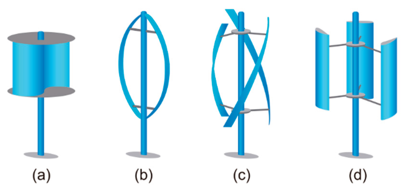
Figure 2.
Schematic of aerodynamic forces acting on the blades of an H-type VAWT.
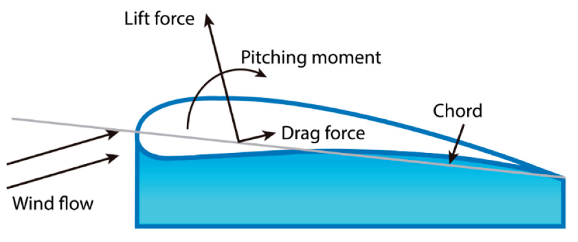
Figure 3.
Transients self-start behavior of a Darrieus H-type wind turbine showing TSR evolution through four operational phases.
Figure 3.
Transients self-start behavior of a Darrieus H-type wind turbine showing TSR evolution through four operational phases.
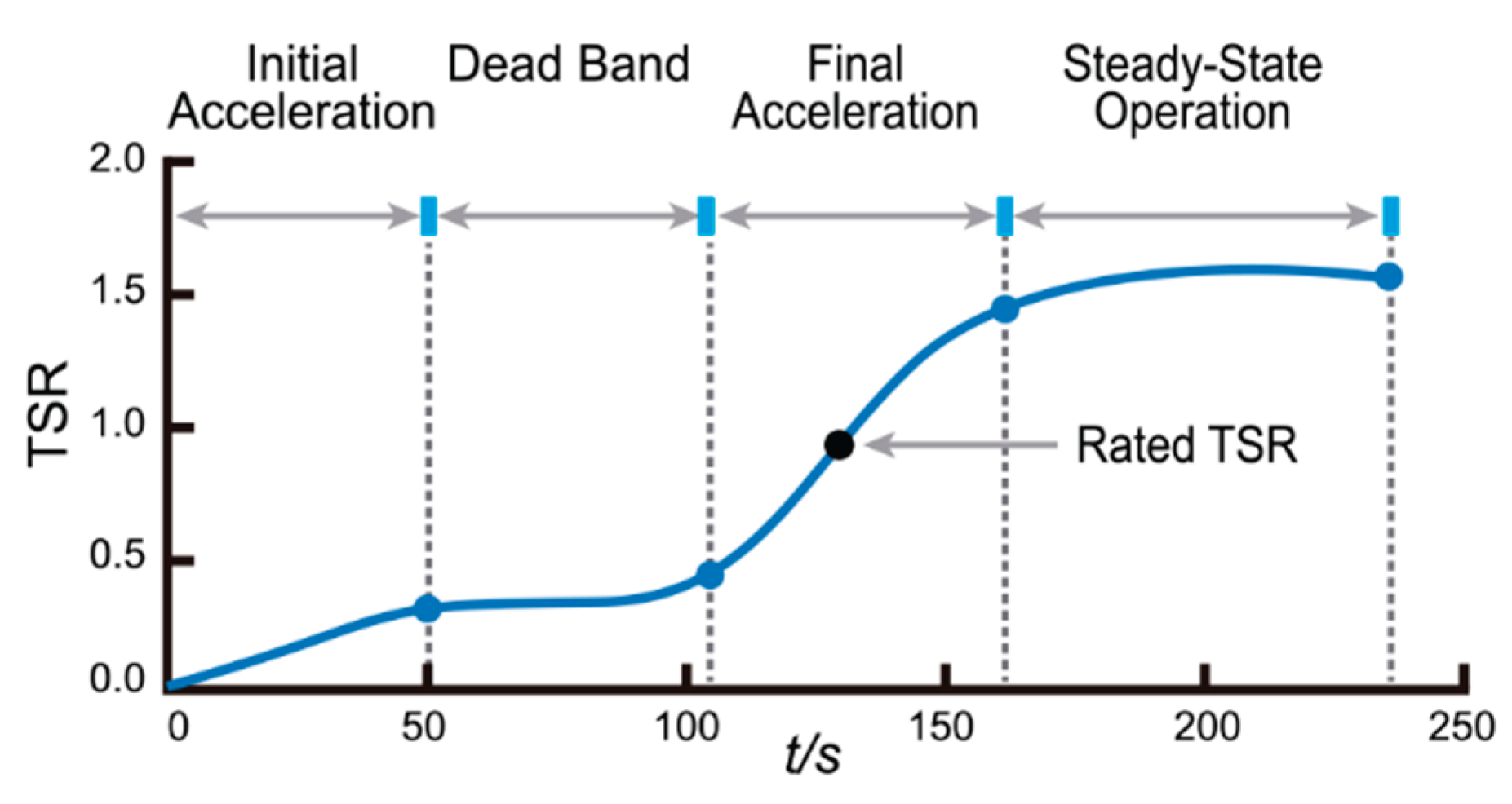
Figure 4.
Velocity triangle and aerodynamic force decomposition on a rotating blade in a Darrieus-type wind turbine. Modified from Celik [21].
Figure 4.
Velocity triangle and aerodynamic force decomposition on a rotating blade in a Darrieus-type wind turbine. Modified from Celik [21].
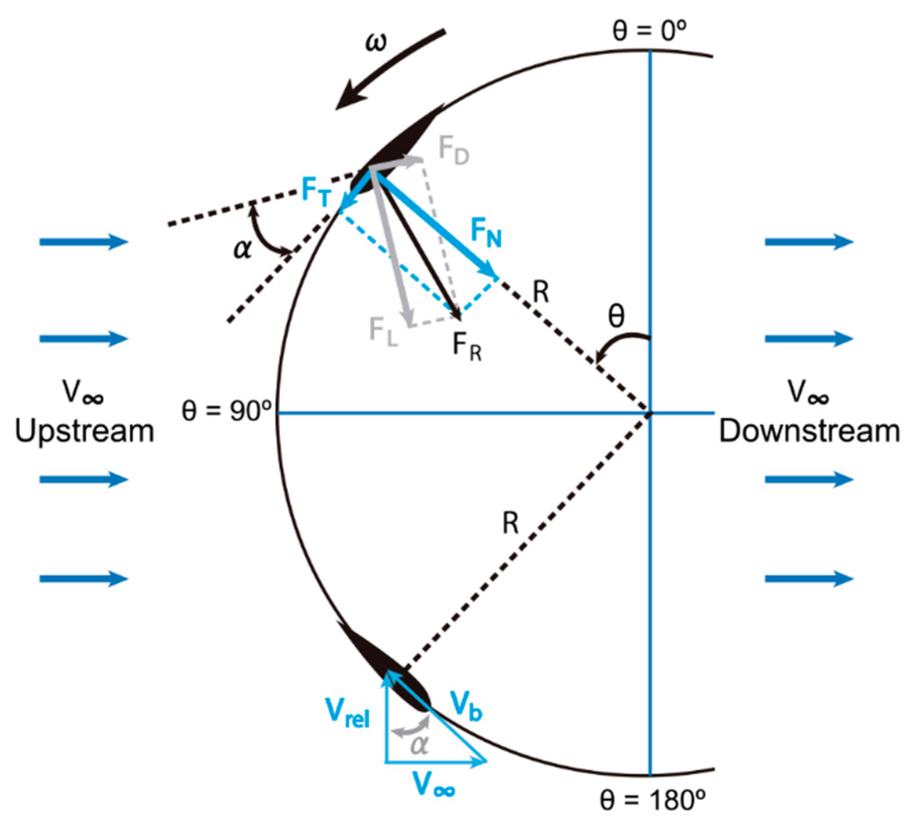
Figure 5.
Characteristic geometric parameters of H-Type Darrieus VAWT.
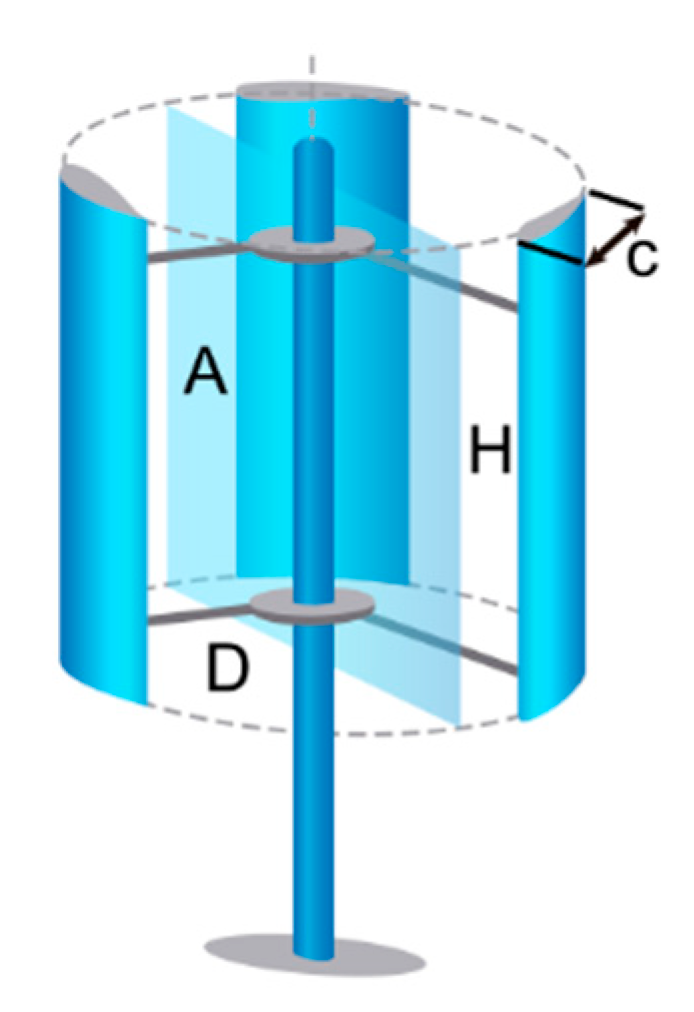
Figure 6.
Surface geometry comparison between (a) S-type and (b) J-type airfoils used in VAWTs blades.
Figure 6.
Surface geometry comparison between (a) S-type and (b) J-type airfoils used in VAWTs blades.
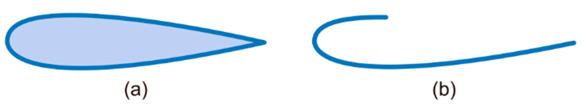
Figure 7.
Three-dimensional vortex distribution over a J-type airfoil, showing flow behavior variation along a blade section at TSR = 1. Adapted from Farzadi et al. [35].
Figure 7.
Three-dimensional vortex distribution over a J-type airfoil, showing flow behavior variation along a blade section at TSR = 1. Adapted from Farzadi et al. [35].
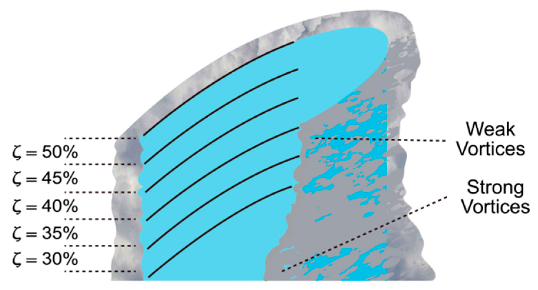
Figure 8.
Geometric comparison of airfoil configurations: (a) baseline NACA4415, (b) J-type profile with lower-surface cut, (c) J-type profile with upper-surface cut. Adapted from Naik and Sahoo [36].
Figure 8.
Geometric comparison of airfoil configurations: (a) baseline NACA4415, (b) J-type profile with lower-surface cut, (c) J-type profile with upper-surface cut. Adapted from Naik and Sahoo [36].
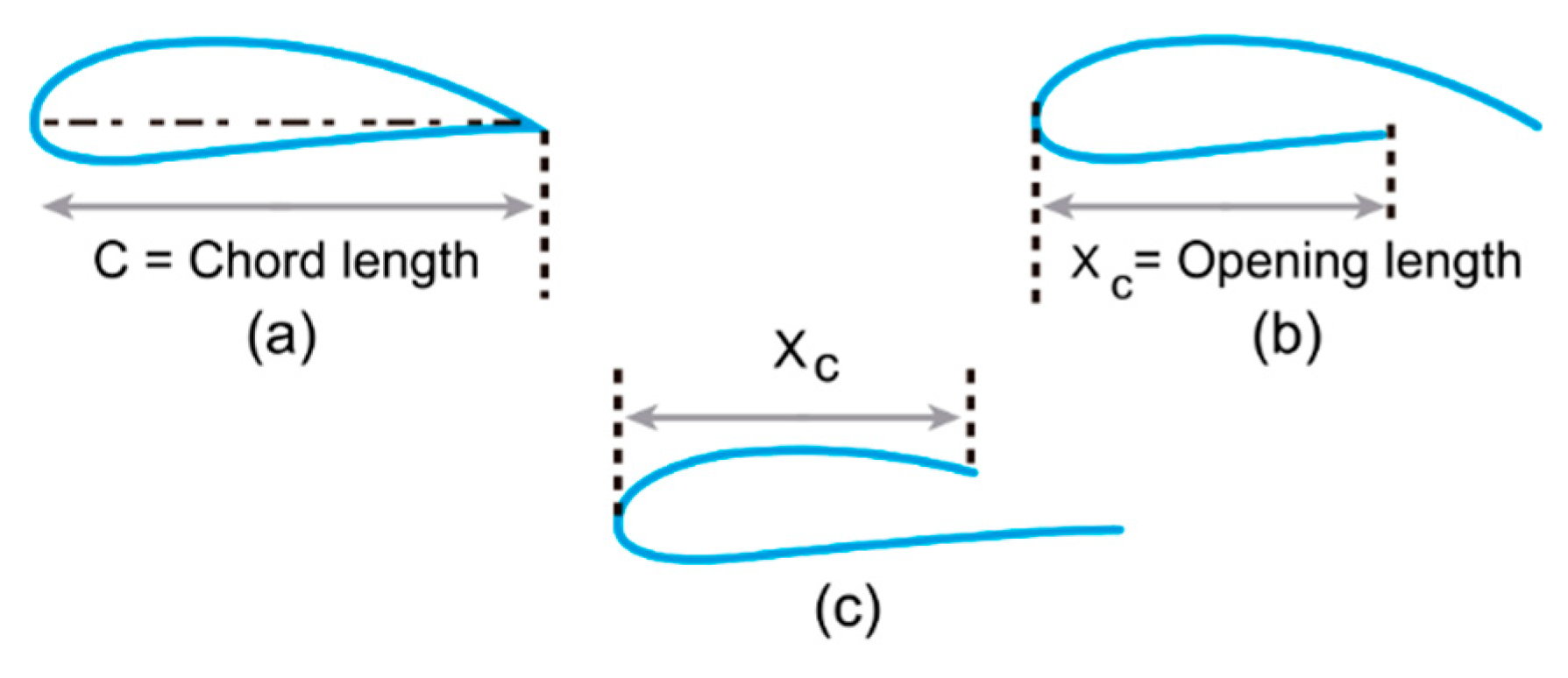
Figure 9.
Geometric variations of J-type airfoils with different opening ratios (OR), as used by Celik et al. [40].
Figure 9.
Geometric variations of J-type airfoils with different opening ratios (OR), as used by Celik et al. [40].
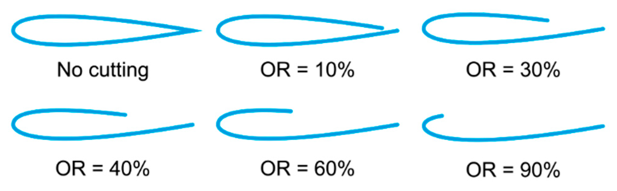
Figure 10.
Proposed hybrid blade configuration with a central NACA0018 section and J-type tips featuring a 40% OR, including NACA0018 end caps. Image adapted from Celik et al. [41].
Figure 10.
Proposed hybrid blade configuration with a central NACA0018 section and J-type tips featuring a 40% OR, including NACA0018 end caps. Image adapted from Celik et al. [41].
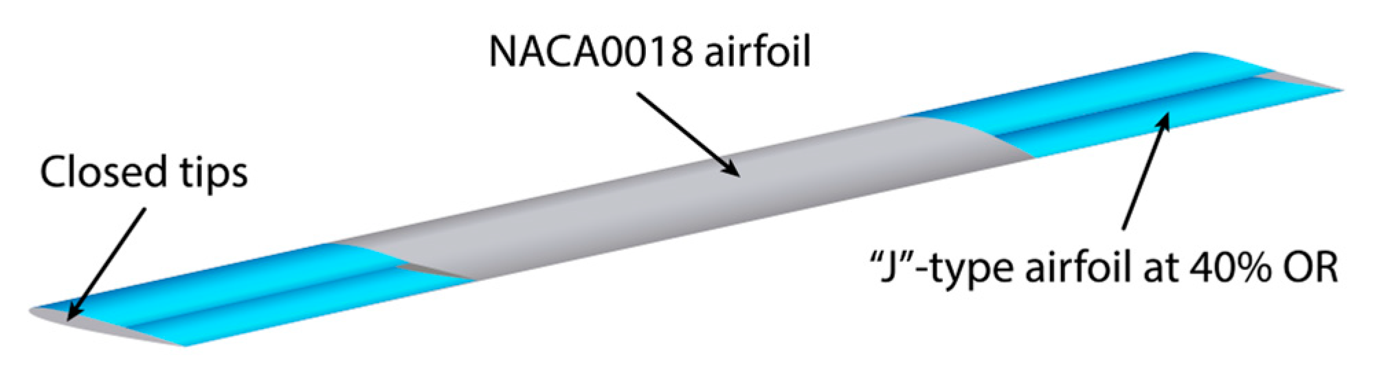
Figure 11.
Five-bladed H-type Darrieus wind turbine with a variable solidity mechanism for enhanced multi-stage performance, as proposed by Huang et al. [42].
Figure 11.
Five-bladed H-type Darrieus wind turbine with a variable solidity mechanism for enhanced multi-stage performance, as proposed by Huang et al. [42].
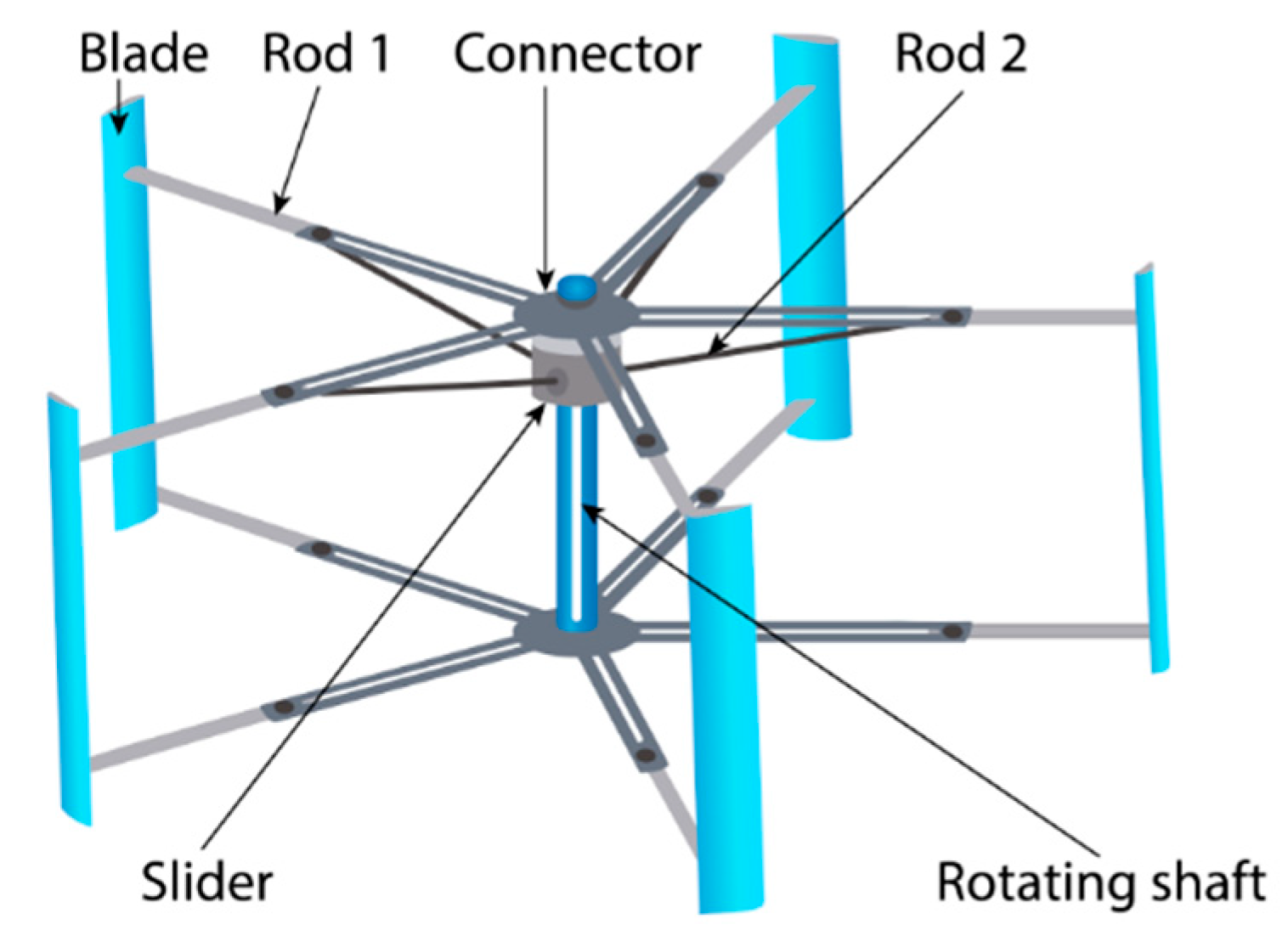
Figure 12.
Six-bladed H-type Darrieus turbine with a locally variable radius (R₁/R₂) for improved self-starting performance, as proposed by Huang et al. [43].
Figure 12.
Six-bladed H-type Darrieus turbine with a locally variable radius (R₁/R₂) for improved self-starting performance, as proposed by Huang et al. [43].
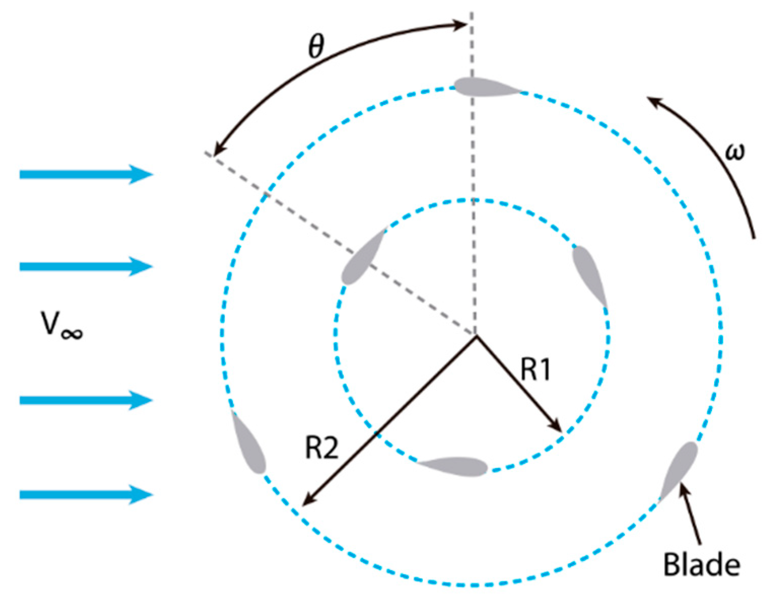
Figure 13.
Dual-row VAWT configuration with outer conventional blades and inner J-type blades, as proposed by Mirzaeian et al. [45].
Figure 13.
Dual-row VAWT configuration with outer conventional blades and inner J-type blades, as proposed by Mirzaeian et al. [45].
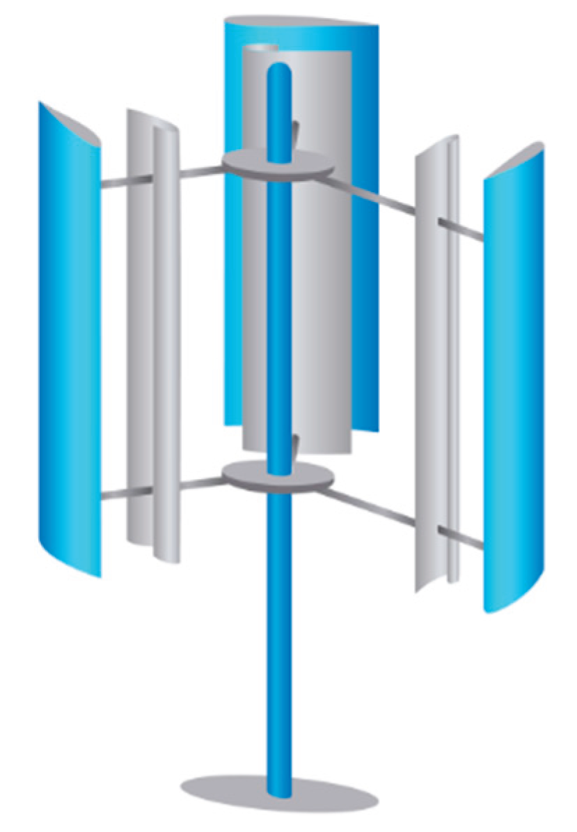
Figure 14.
Hybrid Darrieus-based VAWT with dual concentric rotors: inner curved DU06-W-200 blades and outer straight NACA0018 blades, as proposed by Ahmad et al. [46].
Figure 14.
Hybrid Darrieus-based VAWT with dual concentric rotors: inner curved DU06-W-200 blades and outer straight NACA0018 blades, as proposed by Ahmad et al. [46].
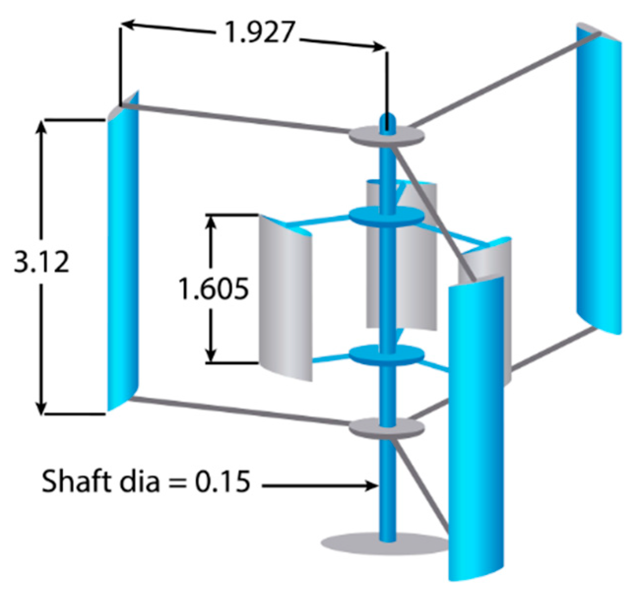
Figure 15.
Textured NACA0015 blade with surface embossing for self-starting enhancement, as investigated by Seifi et al. [7].
Figure 15.
Textured NACA0015 blade with surface embossing for self-starting enhancement, as investigated by Seifi et al. [7].
Figure 16.
Dual-stage VAWT configurations with 30° phase-shifted rotors and integrated auxiliary blades. Modified from [48].
Figure 16.
Dual-stage VAWT configurations with 30° phase-shifted rotors and integrated auxiliary blades. Modified from [48].
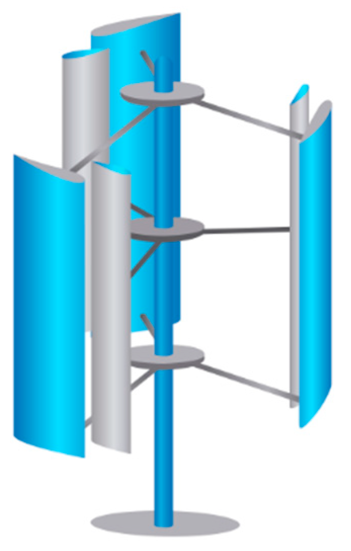
Figure 17.
Conceptual diagram of a dual-stage Darrieus-type VAWT with a 90° inter-rotor phase shift. Modified from [49].
Figure 17.
Conceptual diagram of a dual-stage Darrieus-type VAWT with a 90° inter-rotor phase shift. Modified from [49].
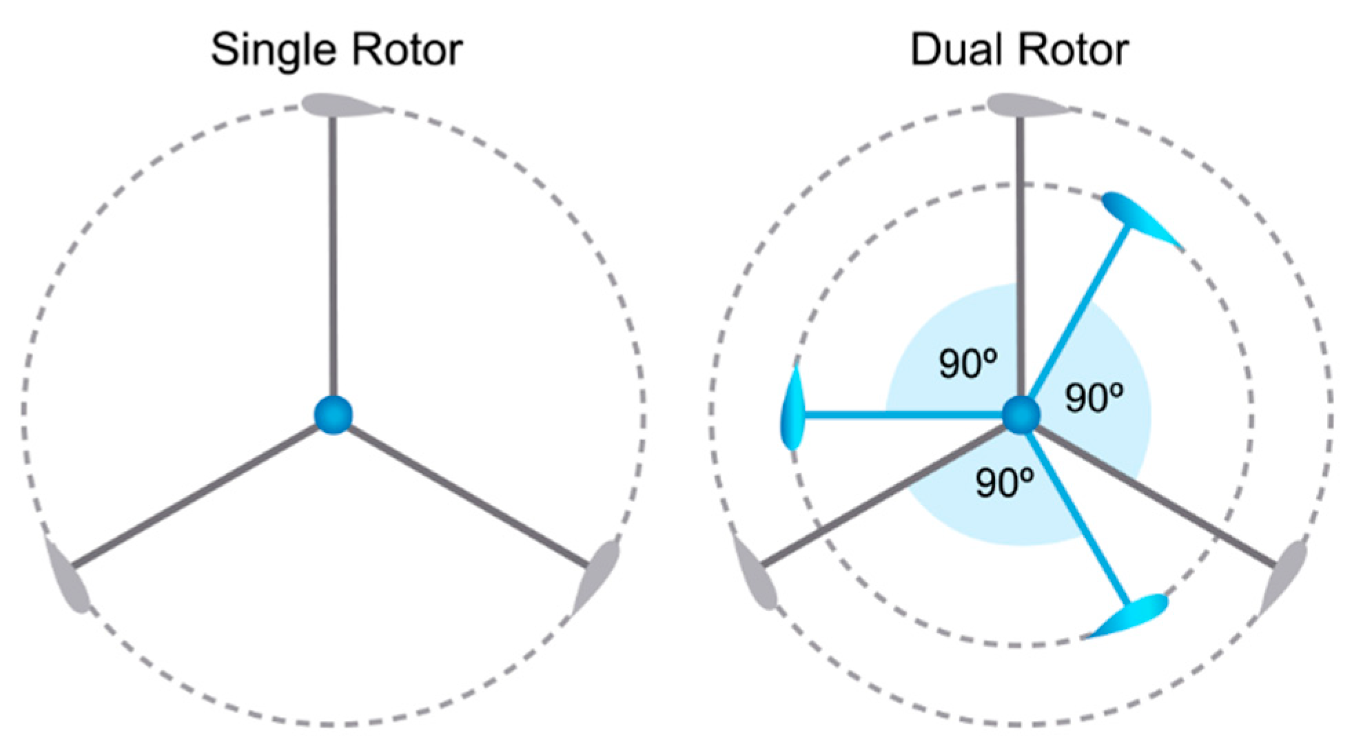
Figure 18.
Schematic representation of GF configurations: (a) unilateral and (b) bilateral “fish-tail” type. Modified from [51].
Figure 18.
Schematic representation of GF configurations: (a) unilateral and (b) bilateral “fish-tail” type. Modified from [51].
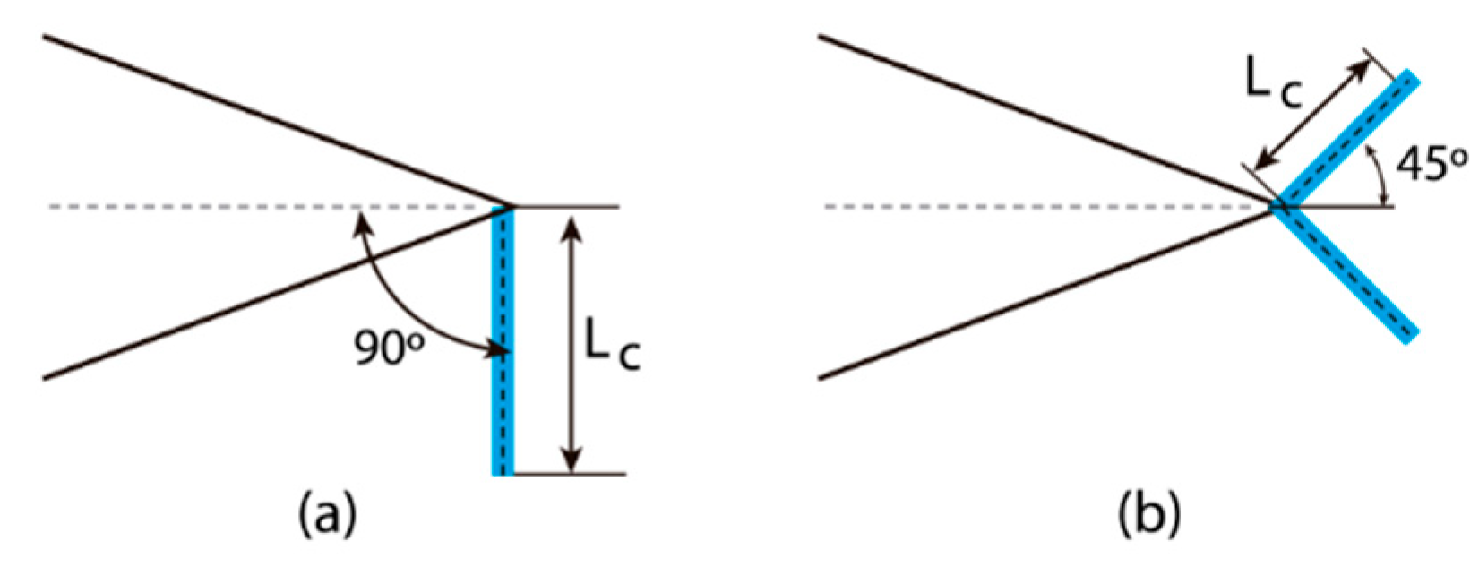
Figure 19.
Geometric configurations of Gurney Flaps (GF) and Planar Fins (PF) evaluated on NACA0015 blades, as studied by Eltayeb and Somlal [56].
Figure 19.
Geometric configurations of Gurney Flaps (GF) and Planar Fins (PF) evaluated on NACA0015 blades, as studied by Eltayeb and Somlal [56].
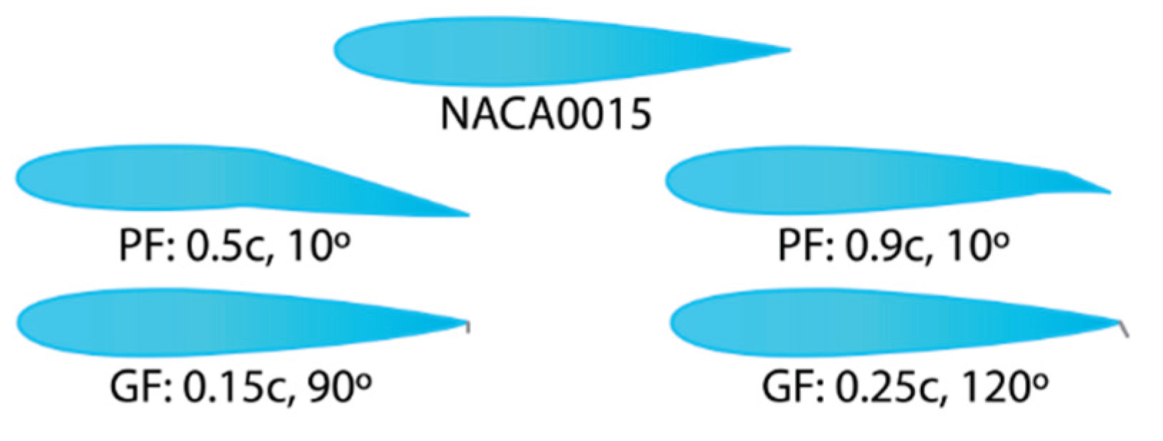
Figure 20.
Circular cavity configurations on NACA0021 blades evaluated for self-starting improvement, based on Yousefi et al. [60].
Figure 20.
Circular cavity configurations on NACA0021 blades evaluated for self-starting improvement, based on Yousefi et al. [60].
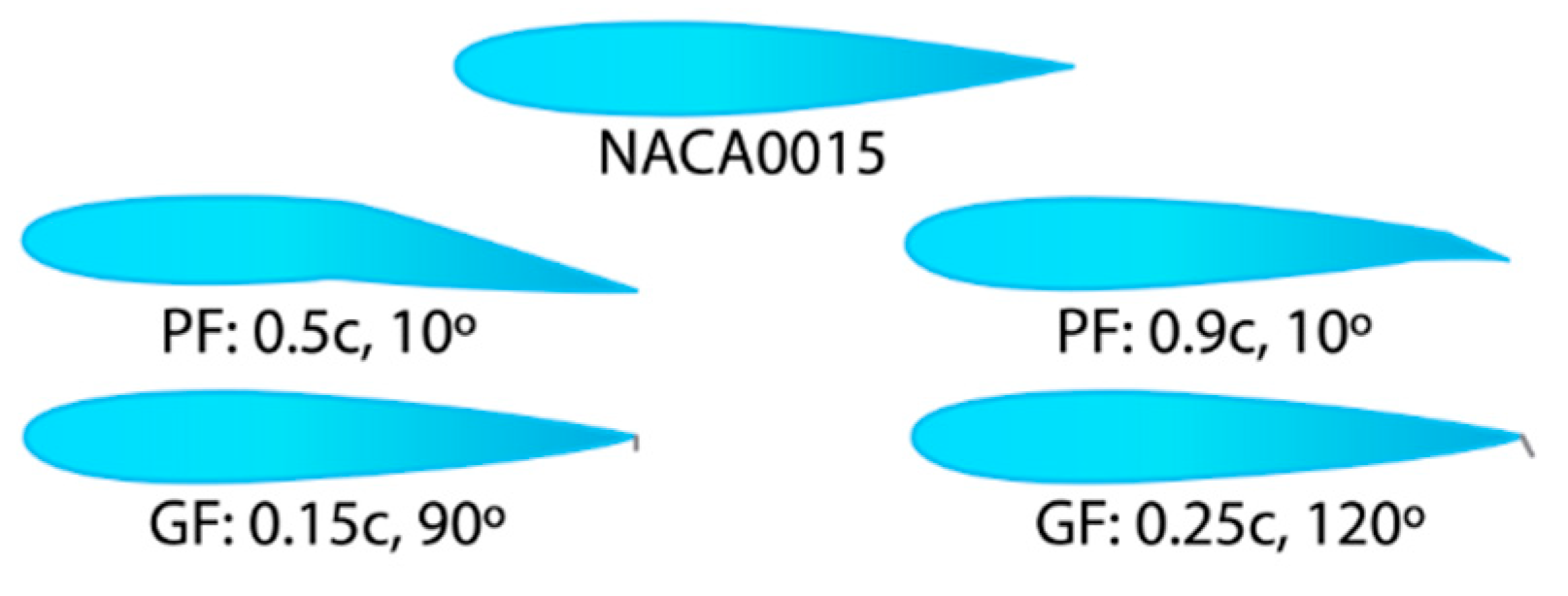
Figure 21.
NACA0012 airfoil with flow-control slots used for self-starting enhancement, as proposed by Mitchell et al. [62].
Figure 21.
NACA0012 airfoil with flow-control slots used for self-starting enhancement, as proposed by Mitchell et al. [62].
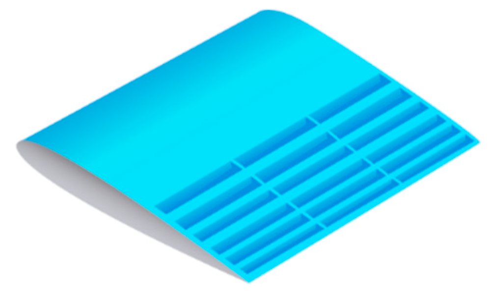
Figure 22.
NACA0021 airfoil with combined Gurney flap and circular cavity configurations, as analyzed by Zhu et al. [63].
Figure 22.
NACA0021 airfoil with combined Gurney flap and circular cavity configurations, as analyzed by Zhu et al. [63].
Figure 23.
Gurney flap configurations applied to J-type airfoils: (a) internal side, (b) external side, and (c) both sides, as evaluated by Kord and Bazargan [64].
Figure 23.
Gurney flap configurations applied to J-type airfoils: (a) internal side, (b) external side, and (c) both sides, as evaluated by Kord and Bazargan [64].
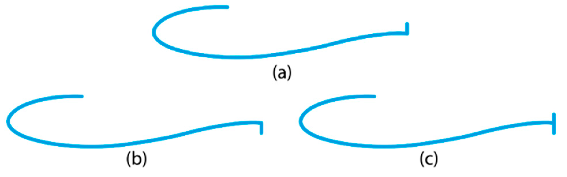
Figure 24.
Biomimetic blade geometries with leading-edge protuberances (LEPs) of varying amplitude: (a) straight blade, (b) large-amplitude LEP1, (c) moderate-amplitude LEP2, and (d) low-amplitude LEP3, inspired by humpback whale flippers [33].
Figure 24.
Biomimetic blade geometries with leading-edge protuberances (LEPs) of varying amplitude: (a) straight blade, (b) large-amplitude LEP1, (c) moderate-amplitude LEP2, and (d) low-amplitude LEP3, inspired by humpback whale flippers [33].
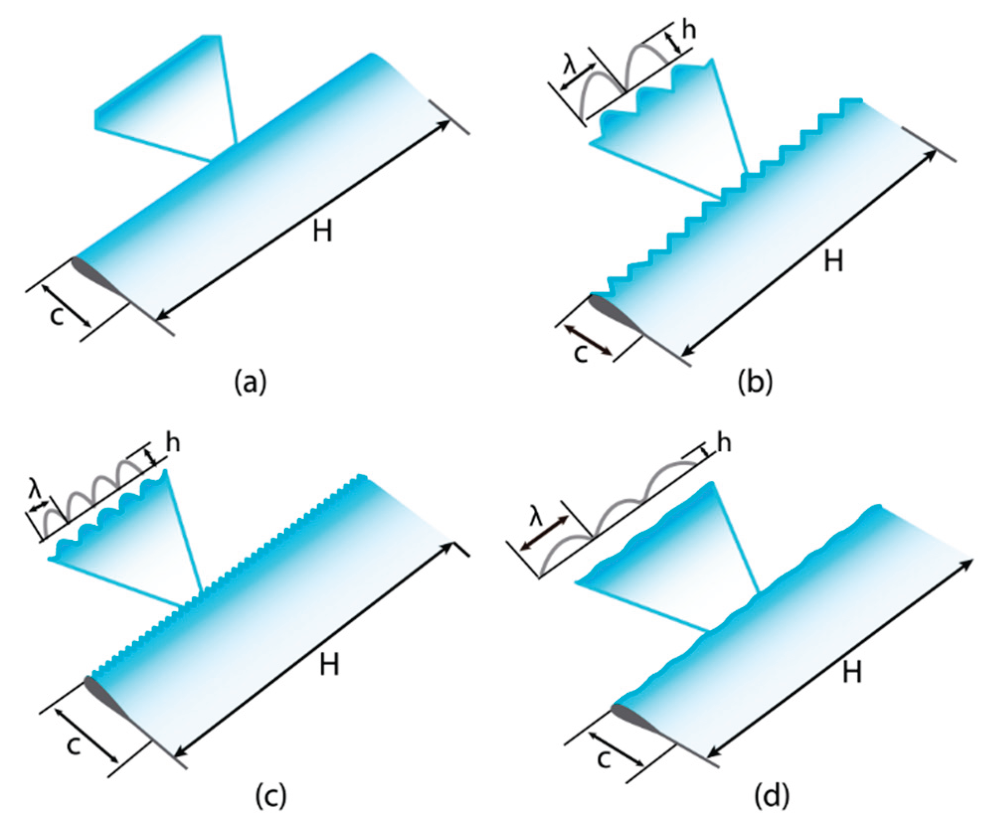
Figure 25.
Schematic diagram of a NACA0018 airfoil featuring a biomimetic sinusoidal leading-edge protuberance, illustrating amplitude (h) and wavelength (λ) parameters [65].
Figure 25.
Schematic diagram of a NACA0018 airfoil featuring a biomimetic sinusoidal leading-edge protuberance, illustrating amplitude (h) and wavelength (λ) parameters [65].
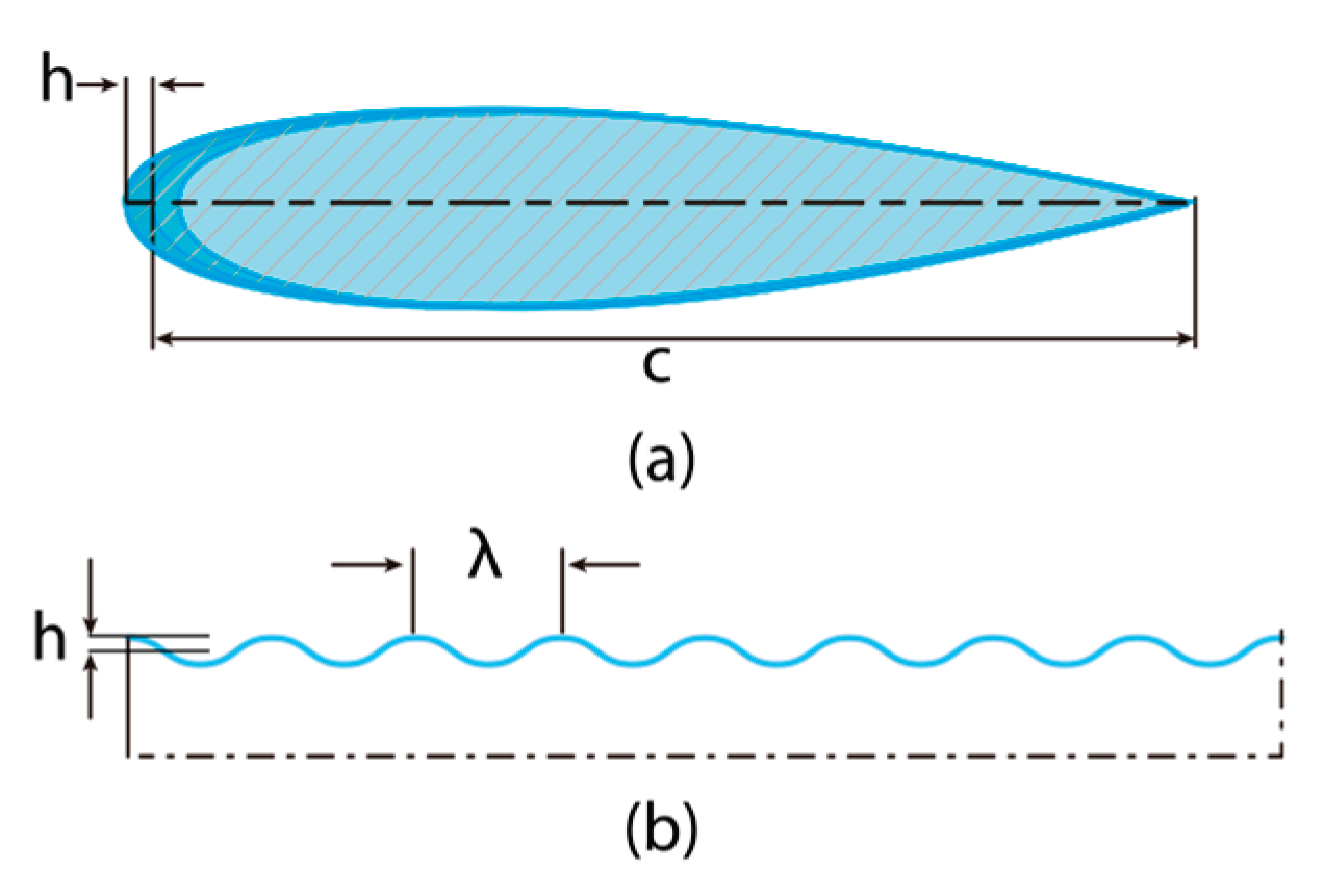
Figure 26.
Application of porous material on the pressure side of a DU06-W-200 airfoil, as modeled in Zamani et al. [66].
Figure 26.
Application of porous material on the pressure side of a DU06-W-200 airfoil, as modeled in Zamani et al. [66].
Figure 27.
NACA0018 airfoil modified with a longitudinal slot to enhance aerodynamic performance, as studied by Mohamed et al. [67].
Figure 27.
NACA0018 airfoil modified with a longitudinal slot to enhance aerodynamic performance, as studied by Mohamed et al. [67].
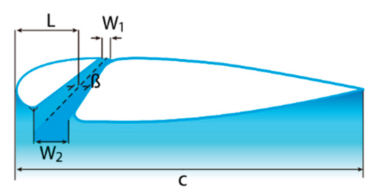
Figure 28.
Operating principle and schematic implementation of Dielectric Barrier Discharge (DBD) plasma actuators for active flow control in VAWT blades [69].
Figure 28.
Operating principle and schematic implementation of Dielectric Barrier Discharge (DBD) plasma actuators for active flow control in VAWT blades [69].
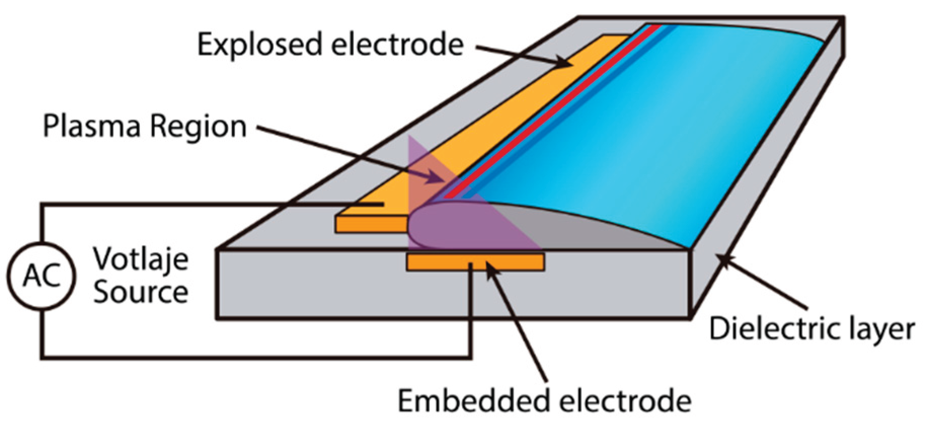
Figure 29.
Hybrid active control system integrating drag and lift modes in an adaptive-blade Darrieus VAWT, as proposed by Gao et al. [76].
Figure 29.
Hybrid active control system integrating drag and lift modes in an adaptive-blade Darrieus VAWT, as proposed by Gao et al. [76].
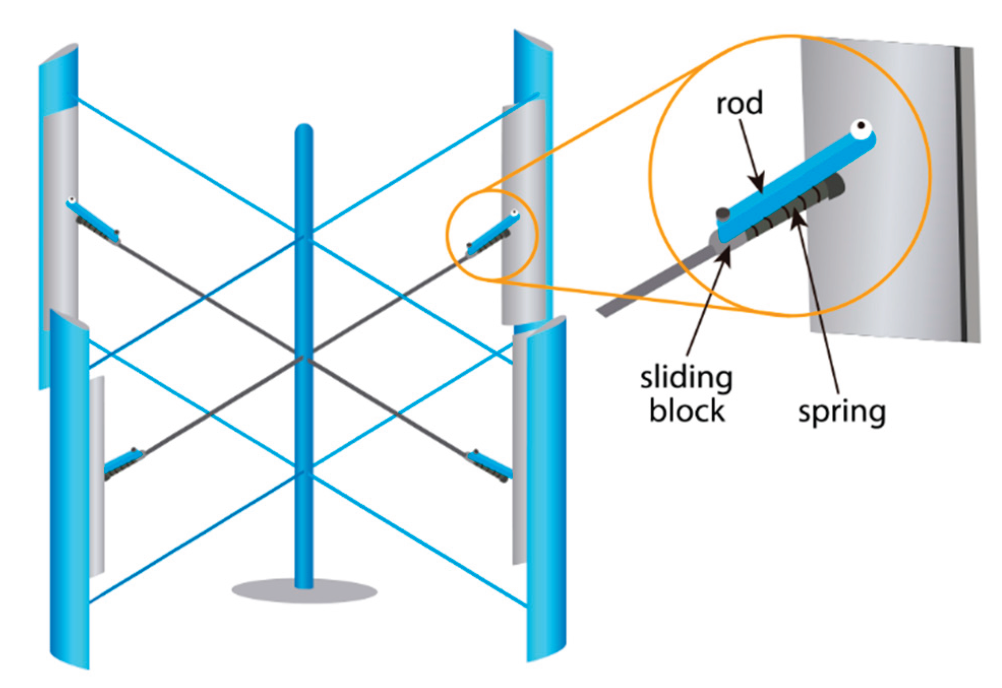
Figure 30.
VAWT configuration with integrated auxiliary blades and deflectors to enhance starting performance and efficiency, as investigated by Ghafoorian et al. [8].
Figure 30.
VAWT configuration with integrated auxiliary blades and deflectors to enhance starting performance and efficiency, as investigated by Ghafoorian et al. [8].
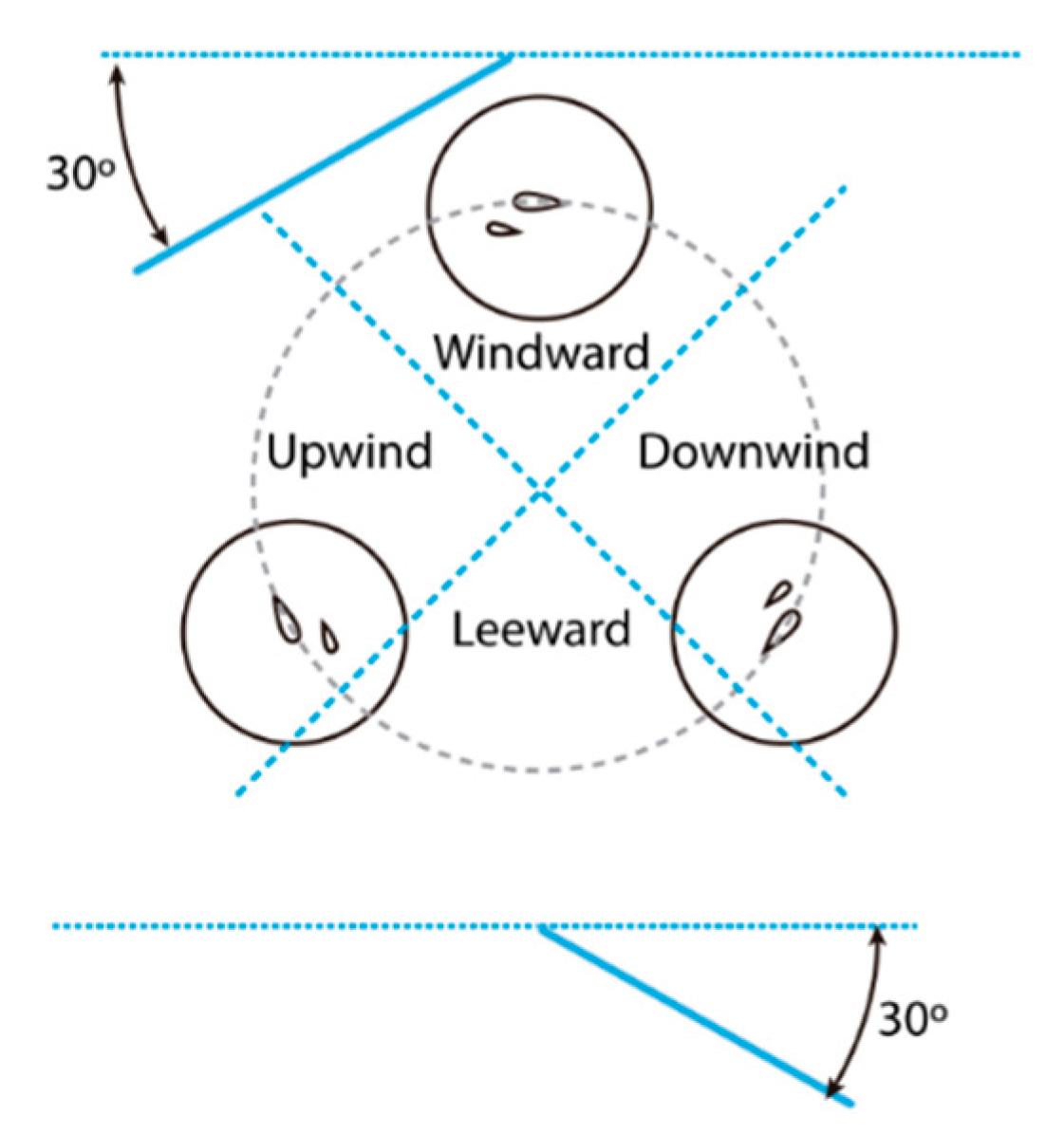
Figure 31.
Aerodynamic enhancement of a five-blade Darrieus VAWT using a downstream passive diffuser, as studied by Wang et al. [79].
Figure 31.
Aerodynamic enhancement of a five-blade Darrieus VAWT using a downstream passive diffuser, as studied by Wang et al. [79].
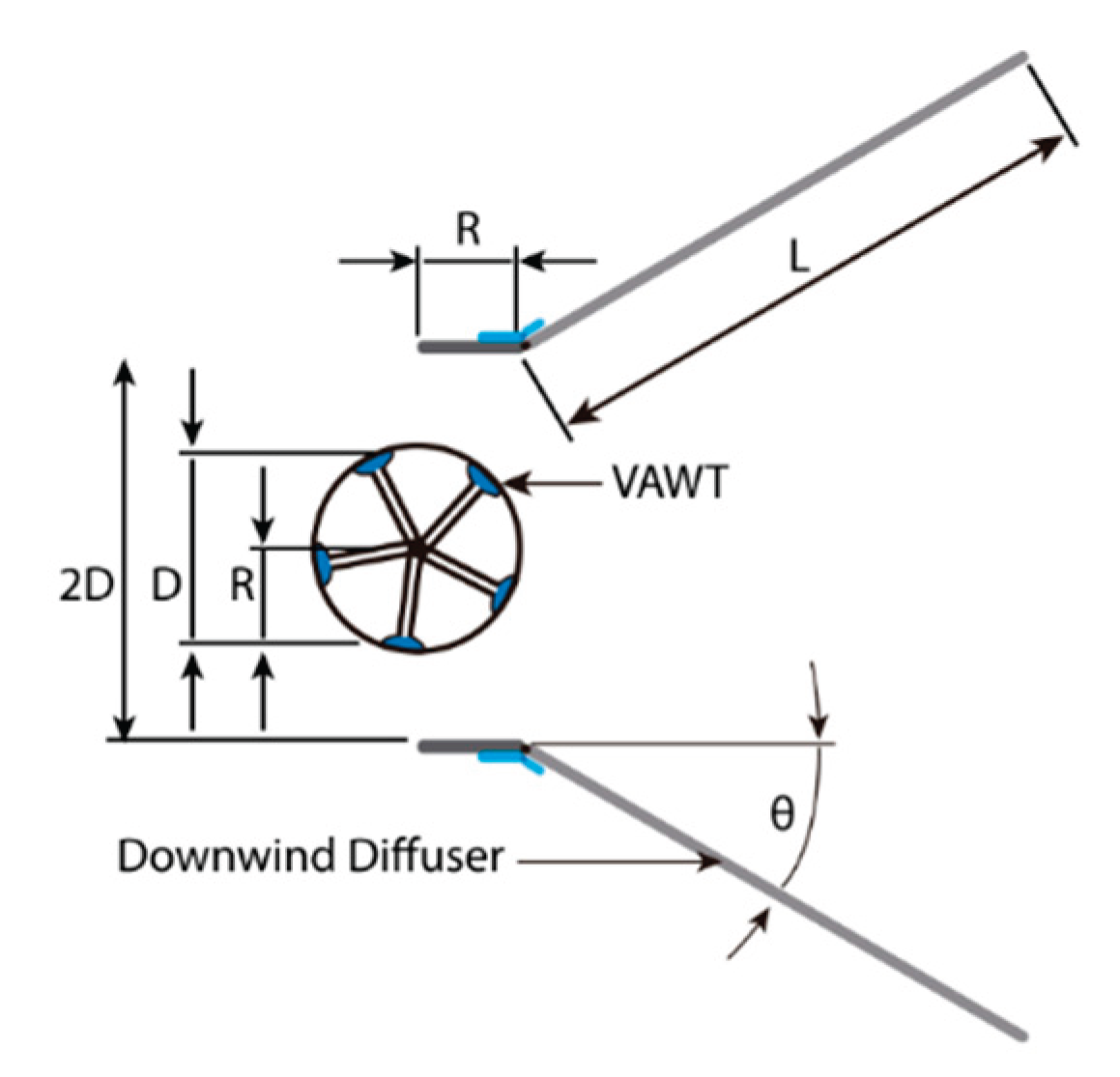

Table 1.
Aerodynamic profile design strategies for improving VAWT self-starting performance.
| Reference | Method | VAWT Parameters | TSR, Wind Speed | Self-Starting Improvement Results |
|---|---|---|---|---|
| [35] | CFD Simulations (2D/3D), URANS, k-ω SST & k-ε | NACA0021, J-profile; N=3, D=1.2 m, H=0.8–3.0 m, c=0.2 m | λ = 0.25 – 1.5 =10.0 m/s |
J-profile improves startup torque, especially for long blades and low TSR. |
| [28,36] | CFD Simulations (2D), URANS, k-ω SST; Experimental Wind Tunnel Tests | NACA4418/4415, J-profile; N=3, D=2.5 m, H=1.0 m, c=0.4 m | λ = 1.6 =10.0 m/s |
J-profile enhances torque at low TSR; 70% OR gives ~25% efficiency gain; top-surface cut performs better. |
| [37] | CFD Simulations (3D), URANS, k-ω SST | NACA0021, J-profile; N=3, D=1.2 m, H=1.2 m, c=0.2 m | λ = 0.5 – 1.5 = 5.0 - 20.0 m/s |
J-profile increases startup torque by 37.6% at 5 m/s and 26.9% at 10 m/s; less efficient at high TSR. |
| [38] | CFD Simulations (3D), URANS, k-ω SST & k-ε; FEA Structural Analysis | NACA0015, J-profile; N=3, D=2.5 m, H=3.0 m, c=0.4 m | λ = 0.6 – 1.6 =10.0 m/s |
18.34% improvement in startup torque (k-ω SST); 5.84% (k-ε); aluminum alloy used. |
| [39] | CFD Simulations (2D), k-ω SST; Taguchi Optimization | NACA0012/15/17/21; c=0.2–0.8 m; β=0°, 2°, 4°; N=3, D=0.85 m | λ = 0 – 3.5 =7.0 m/s |
Longer chord improves transient startup; NACA0017, c=0.6 m, β=4° yielded best overall performance. |
| [40] | CFD Simulations (2D), k-ω SST, SIMPLE Algorithm | Various base airfoils (NACA0012/18/25/45); OR 0–90%; N=3, D=0.75 m, H=0.6 m, c=0.083 m | λ = 1.5 (Bajo) -3.0 (Alto) =4.0 - 6.0 m/s |
OR = 90% improves self-start at low TSR; OR = 10% fails to initiate rotation; β = 2° optimal. |
| [41] | CFD Simulations (2D/3D), RANS, Self-start Model | NACA0018 center + J-profile tips (OR=40%); N=3, D=0.75 m, H=3.0 m, c=0.083 m | λ = 1.5 (Bajo) -3.0 (Alto) =5.0 m/s |
Hybrid blade (NACA0018 center + J-tips) showed best startup performance and peak efficiency. |
Table 2.
Design configuration strategies to enhance self-starting in Darrieus-type VAWT.
| Reference | Method | VAWT Parameters | TSR, Wind Speed | Self-Starting Improvement Results |
|---|---|---|---|---|
| [7] | DMST, MATLAB, PSO optimization | NACA0015/4412/4415; N=3, R=0.175 m, H=0.35–0.75 m, c=0.071 m | λ=0–3.0, =1.0–10.0 m/s |
Optimized NACA0015 with embossing required 0.0805 Nm start torque (21.97% better). |
| [17] | Experimental, Closed-circuit wind tunnel | NACA0018/4418; H and helical blades; β=0°, -3°, -6°; D=0.68 m, RA=1.25, c=0.172 m | λ=0.25–3.0, =5.0 m/s | Straight blades require less start time; NACA0018 offers higher CP but lower start; NACA4418, vice versa. |
| [26] | DMST, MATLAB, Wind tunnel with 4 fans | NACA0015, embossed; N=3, R=0.175 m, H=0.35 m, σ=1.15, c=0.071 m | λ=0–2.5, =0.5–11.0 m/s |
Embossed blades reduced starting force by up to 34.6%. |
| [42] | 2D CFD simulation, SST (k-ω), URANS | NACA0018; σ=0.417, 0.83; N=5; D=0.6–2.10 m; Jz=0.0683–0.8362 kgm²; c=0.075 m | λ=1.25–5.0, =7.9 m/s | High solidity favored self-starting, low solidity improved generation; 188% power increase vs fixed solidity. |
| [44] | Experimental, Wind tunnel | NACA0021/4415/DU06W200; β=0°, -2°, -4°; R=0.30–0.45 m; H=0.6–0.7 m; σ=0.67–1.0 | λ=0.2–2.5, =7.0 m/s | Higher AR and some negative β favored self-start; surface roughness helped in high solidity only. |
| [45] | 2D CFD simulation, SST (k-ω), RANS, Taguchi DOE | NACA0015/DU06W200-J; N=3 (inner/outer); c=0.4 m (outer), 0.27 m (inner) | λ=0.5–2.5, 10.0 m/s | Hybrid VAWT reduced downstream vorticity and wake effects, improving low TSR efficiency. |
| [46] | 2D CFD simulation | DU06-W-200 (inner), NACA0018 (outer); N=3 (both) | λ=1.0–5.0 | Positive static torque across all angles, confirming self-starting ability. |
| [47] | 3D CFD, RANS, DMS Q-Blade, DOE (Box-Behnken) | DU06W200; N=3, R=0.789 m, H=1.605 m, σ=0.67–1.0; β=-3.41°; c=0.547 m | λ=1.0–5.0, =2.81–7.5 m/s | Max CP = 0.491 at TSR = 3.0; static torque positive; self-start at 2.81 m/s. |
| [48] | CFD simulation (k-ε), Experimental | NREL S823 + aux blades; N=3, D=0.3 m, c=0.1 m (main), 0.05 m (aux) | λ=0.4–2.0, =6.0 m/s | Auxiliary blades maintained positive torque at all azimuth angles, ensuring self-starting. |
| [49] | 2D CFD simulation, SST (k-ω), URANS | NACA0018; N=3 inner/outer; R=0.5 m; c=0.06 m (outer) | λ=0–6.0, =4.0–10.0 m/s | Phase-shifted twin-rotor VAWTs (30–90°) improved start at ≥4.0 m/s. |
Table 3.
Passive flow control strategies for improving the self-starting capability of Darrieus-type VAWTS.
Table 3.
Passive flow control strategies for improving the self-starting capability of Darrieus-type VAWTS.
| References | Method | VAWT Parameters | TSR, Wind Speed | Self-Starting Improvement Results |
|---|---|---|---|---|
| [9] | CFD 2D, SST (k–ω), URANS | NACA0021 with circular cavity, N=3, D=1.03 m, σ=0.25, c=0.0858 m | λ=1.6–3.1 | Cavities enhance initial torque by reducing separation and stabilizing flow at low to moderate TSR. |
| [23] | CFD 2D | NACA0018 with GF, N=3, R=0.75 m, H=2.25 m, c=0.09 m, GF_H=0.5%–1.75%, GF_W=0.04%–0.12% | λ=2.75–3.75, =9.0 m/s | Improved upstream force and torque stability lead to better blade rotation. |
| [33] | Wind tunnel experiment | S1046 with tubercles N = 4, D = 0.90 m H = 0.70 m, σ = 0.78 c = 0.1435 – 0.16 m β = -20° to 20° |
=6.0 – 20.0 m/s | LEP blades show superior self-starting capability compared to unmodified blades. |
| [51] | CFD 2D, SST (k–ω), URANS | NACA0012/15/18/21 with GF, N=1–3, D=1.03–3.50 m, σ=0.057–0.250, c=0.086–0.200 m, GF_H=0%–5% | λ=3.30–4.45, =8.0–13.0 m/s | Interior GF increases CM, fish-tail GFs enhance torque but reduce CP slightly. |
| [52] | CFD 2D, SST (k–ω), URANS | NACA0018 with GF, N=3, R=0.85 m, c=0.246 m, GF_H=1.0%–5.0% | λ=1.0–3.5, =8.0 m/s | GF delays dynamic stalls, increasing CL, lift-drag ratio, and CM. |
| [53] | CFD 2D, SST (k–ω), URANS | NACA0021 with GF, N=2, R=1.0 m, β=6°, c=0.265 m, GF_H=0.5%–6.0%, GF_A=90°–105° | λ=0.5–3.0, =8.0 m/s | GF at low AOA increases lift and load stability, aiding blade rotation initiation. |
| [54] | CFD 2D, SST (k–ω), URANS | NACA0021 with GF, N=3, R=0.515 m, c=0.0858 m, σ=0.249, GF_H=1%–3% | λ=2.1–6.0, =9.0 m/s | Internal GF at 0.003c yields 21.3% CP improvement at TSR=2.4 with better CM. |
| [55] | CFD 2D, RANS-LES, Taguchi | NACA0021 with GF, D=1.03 m, N=3, c=0.0858 m, GF_H=0.02c–0.04c, GF_A=60°–135°, GF_P=0–0.07c | λ=1.44–3.3, =9 m/s | Optimized GF (0.03c, 90°) at trailing edge improved CP at low TSR, enabling earlier torque generation. |
| [56] | CFD 2D, SST (k–ω), URANS | NACA0015 with GF and PF, N=3, R=1.0–2.5 m, c=0.16–0.4 m, PF_P=0.50c–0.90c, GF_H=0.15c–0.25c, GF_A=90°–120°, PF_A=10°–120° | λ=0.8–4.5, =5–10 m/s | PFs outperform GFs in reducing negative torque and enhancing low speed self-start. PF at 0.7c, 10° yielded maximum CM. |
| [58] | CFD 2D (k-ε), Experimental | S1046, NACA0021 with circular cavities, N=3, D=0.4 m, H=0.4 m, σ=0.6, c=0.08 m | λ=0.5–2.0, =5–7 m/s | Internal cavity improved self-start only at 5 m/s; unmodified performed better at 7 m/s. |
| [60] | CFD 2D, SST (k–ω), URANS | NACA0021 with circular cavities, N=3, R=1.03 m, c=0.0858 m | λ=2.0–3.5, =8.0 m/s | Circular cavities near leading edge boost startup torque. |
| [61] | CFD 2D, URANS, Spalart-Allmaras, GA | NACA0021 with dimples, N=3, D=NE, c=NE | λ=2.5, =9.0 m/s | Small dimples near the trailing edge increase CP and maximize CM via flow separation delay. |
| [62] | CFD 2D, SST (k–ω) | NACA0012 with vent slots, N=3, R=1.0 m, c=0.2 m | λ=0–3.0, =5.0 m/s | Vent slots improve startup torque at AOA >90° and low TSRs. |
| [63] | CFD 2D, SST (k–ω) | NACA0021 with GF + cavities, N=3–6, c=0.0858 m, σ=0.175–0.5, GF_H=2% | λ=1.0–3.1, =9.0 m/s | External GF + dimples increase aerodynamic force at low TSR, aiding startup. |
| [64] | CFD 2D, SST (k–ω), RANS | Du06-W-200 with J-profile and GFs, N=3, D=3.7 m, c=0.297 m, GF_H=0.75%–2.75% | λ=0.6–2.5, =10 m/s | Only internal GF improved CP at high TSR. External or dual flaps lowered global efficiency. |
| [65] | CFD 3D (k-ε), Experimental | NACA0018 with sinusoidal LEPs, N=3, D=0.45 m, H=0.45 m, σ=0.5, c=0.075 m | λ=1.0–4.0, =5.5–9.0 m/s | CP increased to 46% at 5.5 m/s and 20% at 9.0 m/s: better self-starting at 5.5 m/s. |
| [66] | CFD 2D, SST (k–ω), URANS | DU06-W-200 with porous stripes, N=3, D=3.7 m, H=3.3 m, c=0.27 m | λ=0.5–4.0, =10.0 m/s | Porous media on pressure side improve CP and CM, enhancing low speed self-start. |
| [67] | CFD 2D (k–ε) | NACA0018 with slot, N=3, D=4.7 m, c=0.47 m, σ=0.3 | λ=0–4.0, =8.0 m/s | Slotted profile triples CM at TSR<2, enhancing self-start. |
Table 4.
Active flow control strategies for improving the self-starting capability of Darrieus-type VAWTS.
Table 4.
Active flow control strategies for improving the self-starting capability of Darrieus-type VAWTS.
| Reference | Method | VAWT Parameters | TSR, Wind Speed | Self-Starting Improvement Results |
|---|---|---|---|---|
| [71,72] | 2D CFD Simulation URANS model with transition (y–Reθt) |
NACA0021 with plasma actuator N = 3, D = 1.028 m, H = 1.0 m, c = 0.085 m, σ = 0.25 |
λ=2.4 =9.02 m/s |
The plasma actuator mitigates dynamic stall by reducing negative torque at low TSRs, shortens startup time, and increases CP. |
| [73,74] | 2D CFD Simulation URANS with SST (k–ω) model |
NACA0022 with time-varying plasma actuator D = 0.6 m, c = 0.1 m, H = 0.4 m |
λ=2.45 =5.07 m/s |
Time-varying sinusoidal and cosinusoidal forces enhance torque CM and CP by delaying flow separation, enabling improved self-starting capability. |
| [76] | 2D CFD Simulation with 6DOF and RNG k–ε model Experimental wind tunnel tests |
NACA0018 with hybrid drag-lift adaptive blade N = 4, R = 0.66 m, H = 0.73 m, c = 0.1 m |
λ=0 – 5 =6.0 m/s |
Hybrid control lowers cut-in wind speed. At 80° blade opening, torque coefficient CM nearly doubled, confirming improved startup performance. |
| [77] | 2D CFD Simulation URANS with SST (k–ω) model |
NACA0021 with moving Gurney flap and cavity N = 3, D = 1.03 m, c = 0.086 m, σ = 0.25, GFH = 1.5% |
λ=1.43 – 3.29 =9.0 m/s |
The cavity-Gurney flap combination enhances aerodynamic efficiency in specific operating ranges. The moving flap outperforms the fixed one by adapting to blade rotation, reducing negative torque and aiding startup. |
Table 5.
Incident flow augmentation techniques for improved starting performance in Darrieus VAWTS.
| Reference | Method | VAWT Parameters | TSR, Wind Speed | Self-Starting Improvement Results |
|---|---|---|---|---|
| [8] | 2D CFD simulation SST (k–ω) model, URANS |
NACA0021 (main and auxiliary blades), Deflectors N = 3, D = 1.03 m, c = 0.0858 m |
λ=0.5 – 3.5 =9.0 m/s |
Auxiliary blades with optimized pitch angle and position improved efficiency and starting performance. Deflectors only enhanced torque CM. |
| [78] | 2D CFD simulation and experiments SST (k–ω) model, URANS |
NACA0021 with rear flat diffuser N = 5, D = 1.03 m, H = 1.456 m |
λ=1.5 – 4.5 =9.0 m/s |
Downstream diffuser increased maximum CP by 31.42% at TSR 0.65–0.75, and CM by 26.79%. |
| [79] | 2D CFD simulation SST (k–ω) model, URANS |
Hybrid Darrieus: NACA0021, N = 3, D = 1.03 m, c = 0.0858 m Savonius: N = 2, D = 0.2 m |
λ=1.0 – 4.0 =9.0 m/s |
Hybrid Darrieus-Savonius turbine demonstrated self-starting at low TSR. Deflectors counteracted drag effect of Savonius rotor at high TSR. |
| [80] | 2D and 3D CFD simulation SST (k–ω) model, URANS |
NACA0021, Two Darrieus VAWTs N = 3, D = 0.75 m, H = 1.0 m, c = 0.083 m |
λ=1.0 – 4.0 =8.0 m/s |
Optimized turbine arrangement reduced downstream rotor start-up time from 6.7 s to 4.6 s by utilizing the upstream accelerated flow. |
| [81] | 2D CFD simulation SST (k–ω) model |
NACA0018, Upper and lower wind concentrators N = 3, D = 0.6 m, H = 0.5 m, c = 0.1 m |
λ=0.2 – 2.2 =4.0, 5.0, 8.0, 10.0 m/s |
Concentrators increased average CM: 23.3% at 4.0 m/s, 24.7% at 5.0 m/s, 22.8% at 8.0 m/s, 21% at 10.0 m/s. |
Table 6.
Comparative summary of technological strategies to enhance the self-starting of Darrieus-type VAWTS.
Table 6.
Comparative summary of technological strategies to enhance the self-starting of Darrieus-type VAWTS.
| Strategy | Main Objective | Key Advantages | Limitations | Validation Level |
|---|---|---|---|---|
| Aerodynamic Profile Optimization | Increase torque at low TSR by modifying blade shape and parameters | No external systems; effective at low wind speeds | Trade-off with high-TSR efficiency | Mainly 2D CFD; limited experimental validation |
| Structural Configuration | Redistribute aerodynamic forces through blade arrangement and structure | Can enhance torque generation without energy input | Requires structural adjustments; mechanical complexity | Numerical with some experimental models |
| Passive Flow Control | Delay flow separation using surface modifications (e.g., Gurney flaps, cavities) | Low-cost; no external energy required | Limited effectiveness across wide TSR range | Validated in CFD; limited full-scale trials |
| Active Flow Control | Actively modify flow via actuators to boost torque during startup | High adaptability and potential performance boost | Requires energy, complex control systems, and robust materials | Mostly CFD; lacks real-world validation |
| Incident Flow Enhancement | Increase wind speed impacting rotor via ducts, deflectors, auxiliary blades | Improves local wind velocity and startup performance | Space requirements, sensitivity to wind direction | Combination of CFD and experiments; mostly 2D |
Disclaimer/Publisher’s Note: The statements, opinions and data contained in all publications are solely those of the individual author(s) and contributor(s) and not of MDPI and/or the editor(s). MDPI and/or the editor(s) disclaim responsibility for any injury to people or property resulting from any ideas, methods, instructions or products referred to in the content. |
© 2025 by the authors. Licensee MDPI, Basel, Switzerland. This article is an open access article distributed under the terms and conditions of the Creative Commons Attribution (CC BY) license (http://creativecommons.org/licenses/by/4.0/).
Copyright: This open access article is published under a Creative Commons CC BY 4.0 license, which permit the free download, distribution, and reuse, provided that the author and preprint are cited in any reuse.


