Submitted:
30 July 2025
Posted:
31 July 2025
You are already at the latest version
Abstract
Harvesting oil palm is a critical activity in the plantation industry, but prolonged use of manual tools such as dodos and egreks often leads to health issues such as musculoskeletal disorders, repetitive strain injuries, and carpal tunnel syndrome. With advancements in technology, solutions like drones are increasingly being utilized to enhance efficiency in harvesting. This study aims to analyze displacement in relation to variations in brushless motor speed on an oil palm frond cutting system as a drone attachment. Tests were conducted at three motor speeds: 5700 rpm, 8200 rpm, and 9700 rpm, using three types of attachments—chainsaw, dodos, and egrek—at three different points: the gearbox (point 1), shaft pole (point 2), and drive motor (point 3). The average displacement values at motor speeds of 5700 rpm, 8200 rpm, and 9700 rpm were 0.068 mm, 0.089 mm, and 0.089 mm for the chainsaw; 0.785 mm, 2.158 mm, and 2.337 mm for the dodos; and 0.788 mm, 2.160 mm, and 2.364 mm for the egrek. The chainsaw demonstrated relatively smaller displacement compared to the dodos and egrek, indicating a higher level of stability when paired with the drone.
Keywords:
tool design
; displacement
; oil palm
; drone
; dodos
; egrek
; chainsaw
1. Background
Oil palm (Elaeis guineensis Jacq) is an industrial crop that plays a significant role in national development, serving as one of Indonesia’s largest export commodities and contributing substantially to the country’s revenue. In 2018, the oil palm plantation area reached 14.33 million hectares, with a production volume of 42.9 million tons. This growth was primarily driven by the expansion of areas managed by oil palm companies. By 2019, it was projected that the plantation area would increase by 1.88%, reaching 14.60 million hectares, while crude palm oil (CPO) production was expected to rise by 12.92% to 48.42 million tons. This indicates that CPO production in 2019 was anticipated to experience significant growth compared to 2018 [1,2,3,4].
Harvesting and cutting oil palm fronds are typically carried out manually by workers using tools such as dodos and egrek. Health issues commonly experienced by oil palm harvesters include mild musculoskeletal disorders, repetitive strain injuries, and carpal tunnel syndrome [5,6,7].
Technological advancements, particularly in the Internet of Things (IoT), including drone technology that provides mapping and data analysis services, can offer more accurate and efficient information for precision agriculture. In general, IoT technology, especially drones, can collect and process information from various sources, assist in gathering data on weather, soil profiles, and drainage, while simultaneously managing all crops more efficiently [8,9,10].
This study examines the effect of motor speed on the vibrations generated in the cutting system for oil palm fronds, designed as an attachment for drones.
2. Literature Review
2.1. Oil Palm Tree
The oil palm tree (Elaeis guineensis and Elaeis oleifera) is a tropical plant native to West Africa and Central and South America. The oil palm tree has a tall, erect trunk with long, feather-like leaves. It can reach heights of 20 to 30 meters and has a productive lifespan of 25 to 30 years [11,12].
The water content in oil palm fronds is very high, reaching up to 60% when wet. The leaves are located at the top of the plant, arranged like a crown that contains 40 or more fronds. Each oil palm frond has 20 to over 150 pairs of leaflets, approximately 25 mm wide, arranged in two rows along each side of the leaf stem. The length of the frond decreases from the bottom to the top of the crown, reaching a length of around 4 meters. In a cross-section, the frond takes a triangular shape, with the width narrowing from the base to the tip of the leaf stem and from the bottom to the upper fronds. The branches that produce fruit, containing thousands of fruits, are held in the axils of the leaves and arranged in a rosette pattern around the crown [13,14,15,16,17].
2.2. Drone
A UAV (Unmanned Aerial Vehicle) is a device that can fly based on a pre-set program with the assistance of GPS coordinates. This device is also equipped with a radio control system that allows it to be manually operated in emergency or hazardous situations. The term UAV is sometimes used to refer to the entire system, including the ground station and video systems. UAV (Unmanned Aerial Vehicle) is commonly used to refer to aircraft or helicopter models with either fixed wings or rotary wings [18,19].
2.3. Oil Palm Cutting Tools
Currently, most oil palm harvesting in Indonesia is still carried out manually using harvesting tools such as dodos and egrek. Dodos are typically used for shorter plants, while egrek is used for taller plants that are over seven years old [20].
Dodos is a knife used to cut fronds or fruit bunches by pushing, while egrek is a sickle-shaped knife used for cutting fronds or fruit bunches by pulling. The harvesting process using these tools requires significant physical effort and long working hours, which increases the harvesting costs and results in lower profits for farmers [20,21].
2.4. Linear Actuator
A linear actuator is a device that converts energy (such as electrical, pneumatic, or hydraulic energy) into linear motion, which is movement in a single direction along a straight line. The primary function of a linear actuator is to generate the force and linear displacement required to move or position an object. Actuators come in several types, including electric actuators, pneumatic actuators, hydraulic actuators, and mechanical actuators [22,23].
2.5. Mechanical Vibration
Mechanical vibration is the oscillation or back-and-forth movement of an object or mechanical system around its equilibrium position. This vibration is generated by repetitive forces or impulses that cause the mechanical system to oscillate, and it is often influenced by factors such as mass, stiffness, and damping in the system. [26] Mechanical vibration can be either harmonic (periodic) or random, depending on the source of the force causing the oscillation. Vibration needs to be controlled because excessive vibration can lead to damage to machine components or structures. [27,28] Excessive vibration can also cause bolts to loosen, leading to potential mechanical failure or safety hazards [29,30].
3. Research Methodology
3.1. Tools and Materials
In this research, several tools were utilized for the assembly, testing, and data collection process. These included a cable stripper for removing insulation from cables, a soldering iron and solder for joining electronic components, and a MIG welding machine for welding metal parts. A screwdriver set was used for assembling and disassembling components, while a 3D printer helped create custom parts. Cutting and hand pliers were essential for cutting and manipulating small components, and a vise was used to hold objects firmly during work. The drilling machine facilitated drilling holes in materials, and the angle grinder was employed for grinding and cutting. For precise measurements, a caliper was used, and a laptop was necessary for controlling devices, recording data, and performing analysis.
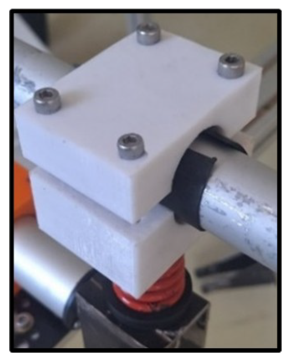
The materials required for this research include: the ESP32 as the main controller, the linear actuator as the mechanical driver, batteries for power supply, relay as a digital switch, motor driver for controlling the linear actuator, controller for issuing commands, and a box for housing the electrical components. Additionally, a step-down module is used to reduce voltage, while bolts and nuts serve to connect the aluminum V-slot. The aluminum V-slot acts as the frame mount, jumper wires for electrical connections, spring mounting to dampen vibrations in the frame, 3D printed components for connecting the linear actuator and spring mounting, and the oil palm cutting tools are used for the cutting process.
3.2. Research Procedure
The stages of this research can be seen in Figure 1 : The Research Flow Diagram below.
3.3. Manufacturing Process
3.3.1. Design Stage
- (a)
-
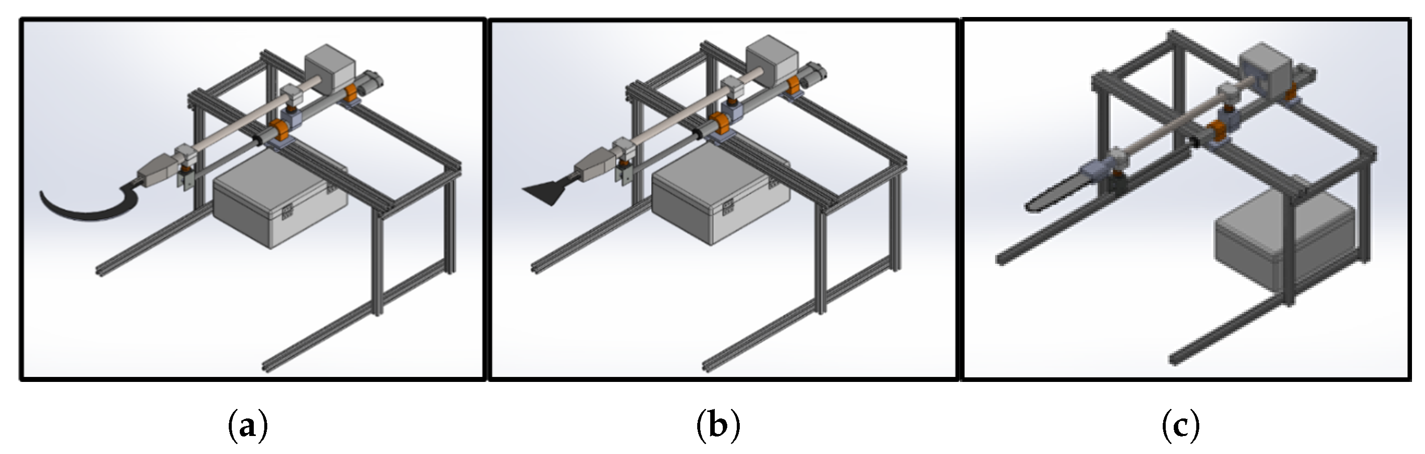
Tool designThe tool design includes three types: the dodos machine, egrek, and chainsaw.Figure 2. (a) Egrek cutting system design. (b) Dodos Cutting system design. (c) Chainsaw cutting system design.Figure 2. (a) Egrek cutting system design. (b) Dodos Cutting system design. (c) Chainsaw cutting system design.
- (b)
-
Electrical DesignThis cutting system is operated using a 14.8 V LiPo battery, with the output voltage being reduced through two modules. The first module is the LM2596, which functions as a step-down regulator, reducing the voltage to 12 V, which is then supplied to the L298N motor driver to control the movement of the linear actuator. This control is carried out via input signals from a DualShock 3 controller processed by the ESP32. The second module is a step-down regulator that reduces the voltage to 5 V, which is used to power the ESP32 and relay. The input from the DualShock 3 controller is processed by the ESP32, which is responsible for activating and deactivating the dodos/egrek machine, which operates with an external battery. The relay is connected to pin D16 on the ESP32, while the motor driver is connected to pin D15, with IN1 and IN2 each connected to pins D2 and D4.The electrical system design of the cutting system, which allows it to be used and controlled remotely, can be seen in Figure 3Table 1. Components in the Electrical System Design of the Cutting System:
No Name No Name 1 Lipo Battery 14.8V 6 Driver motor L298N 2 LM2596 Module StepDown 7 Relay 3 LM2596 Module StepDown 8 Linear actuator 4 Dualshock 3 controller 9 dodos/egrek 5 ESP32 - (c)
-
Coding AlgorithmIn general, the foundation of this program is a system designed to receive input from the DualShock 3 controller. The input received is processed by the ESP32, which serves as the main control unit in the system. After processing, the generated signal allows for the control of the linear actuator’s movement, which can be set to either extend or retreat. Additionally, the program also manages the operational status of the dodos/egrek machine, which can be turned on or off based on the input from the controller.The steps of the cutting system program can be seen in Figure 4

3.3.2. Manufacturing Stage
The manufacturing stage of the cutting system components is carried out based on each component group. The components themselves consist of 2 types.
- (a)
-
The process begins by designing the model in SolidWorks, then exporting it as an STL file for compatibility with slicing applications. This file is imported into the Cura application, where printing parameters such as resolution, speed, and filament type are set. Printing is done using a 3D printer with PETG filament, and the Cura application estimates the printing time based on the settings. Once finished, the components are ready to be used according to the design.
- (b)
-
Steel Socket ComponentsFigure 6. Steel Socket Components that have been made.
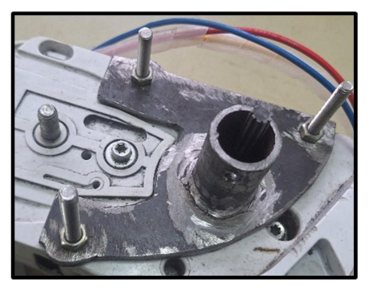 The manufacture of the Steel Socket begins with selecting a 5 mm thick iron plate and a 30 mm diameter pipe. The plate is cut according to the pattern using a grinder, and holes are drilled following the design. The plate and pipe are then welded together using MIG welding. After cutting, drilling, and welding, the component undergoes a finishing process, including smoothing the welded Steel Socket.
3.3.3. Assembly Stage
Figure 7.
Component Description in the Cutting System.
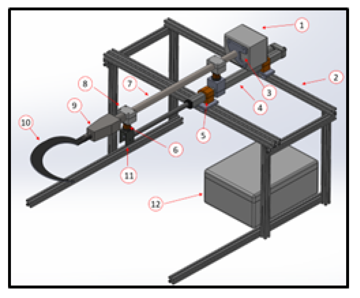
Table 2.
Components Description
| No | Component name | No | Component name |
|---|---|---|---|
| 1 | Cordless machine | 7 | Dodos/Egrek pole |
| 2 | Mounting Frame | 8 | 3D-Printed Connector for Spring Mounting and Dodos/Egrek |
| 3 | Steel Socket | 9 | Cutting Tool Gearbox |
| 4 | Linear Actuator | 10 | Egrek |
| 5 | 3D-Printed Connector for Frame and Linear Actuator | 11 | Steel Socket for Linear Actuator and Spring Mounting |
| 6 | Spring Mounting | 12 | Electrical box |
Figure 8.
(a) Results of the Oil Palm Frond Cutting System (Egrek). (b) Results of the Oil Palm Frond Cutting System (Dodos). (c) Results of the Oil Palm Frond Cutting System (Chainsaw).
Figure 8.
(a) Results of the Oil Palm Frond Cutting System (Egrek). (b) Results of the Oil Palm Frond Cutting System (Dodos). (c) Results of the Oil Palm Frond Cutting System (Chainsaw).
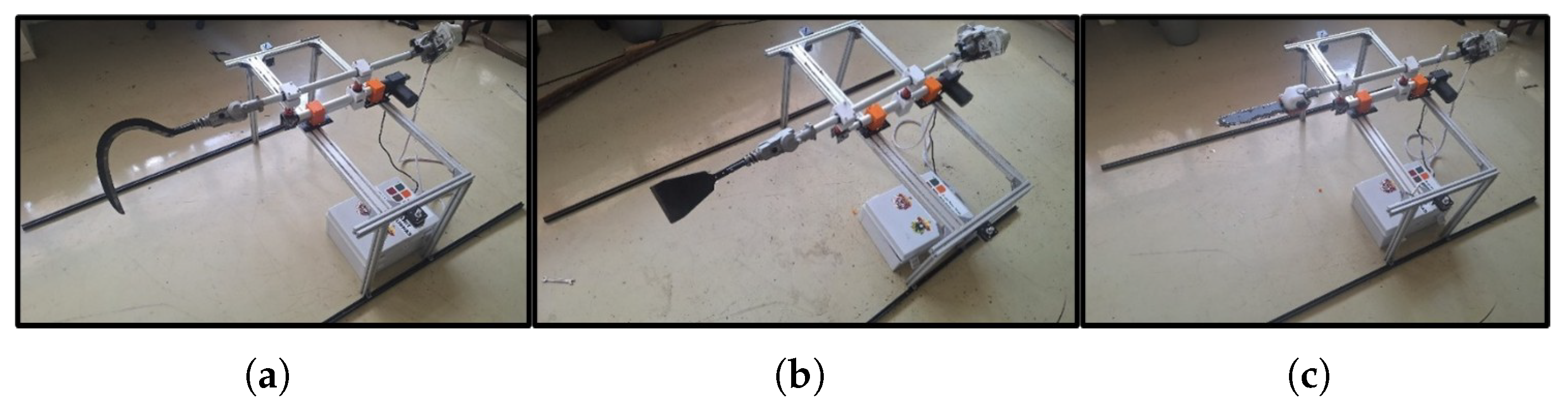
Table 3.
Specifications of the Cutting System.
| Tool Specification | ||
|---|---|---|
| Tool Dimensions | : | 1600 x 280 x 240 mm |
| Motor Rotation Capability | : | 0–9700 rpm |
| Electrical Power Supply | : | 40 V |
| Brushless Motor Power Supply | : | 10.6 kg |
| Minimum Tool Length | : | 160 mm |
| Frame Dimensions | : | 2000 x 660 x 640 mm |
| Maximum Tool Length | : | 200 mm |
3.3.4. Testing Stage
After the entire cutting system is assembled, the tool is activated by turning on the main switch inside the electrical box, which is then connected to the controller.
Figure 9.
The vibration reading area points.
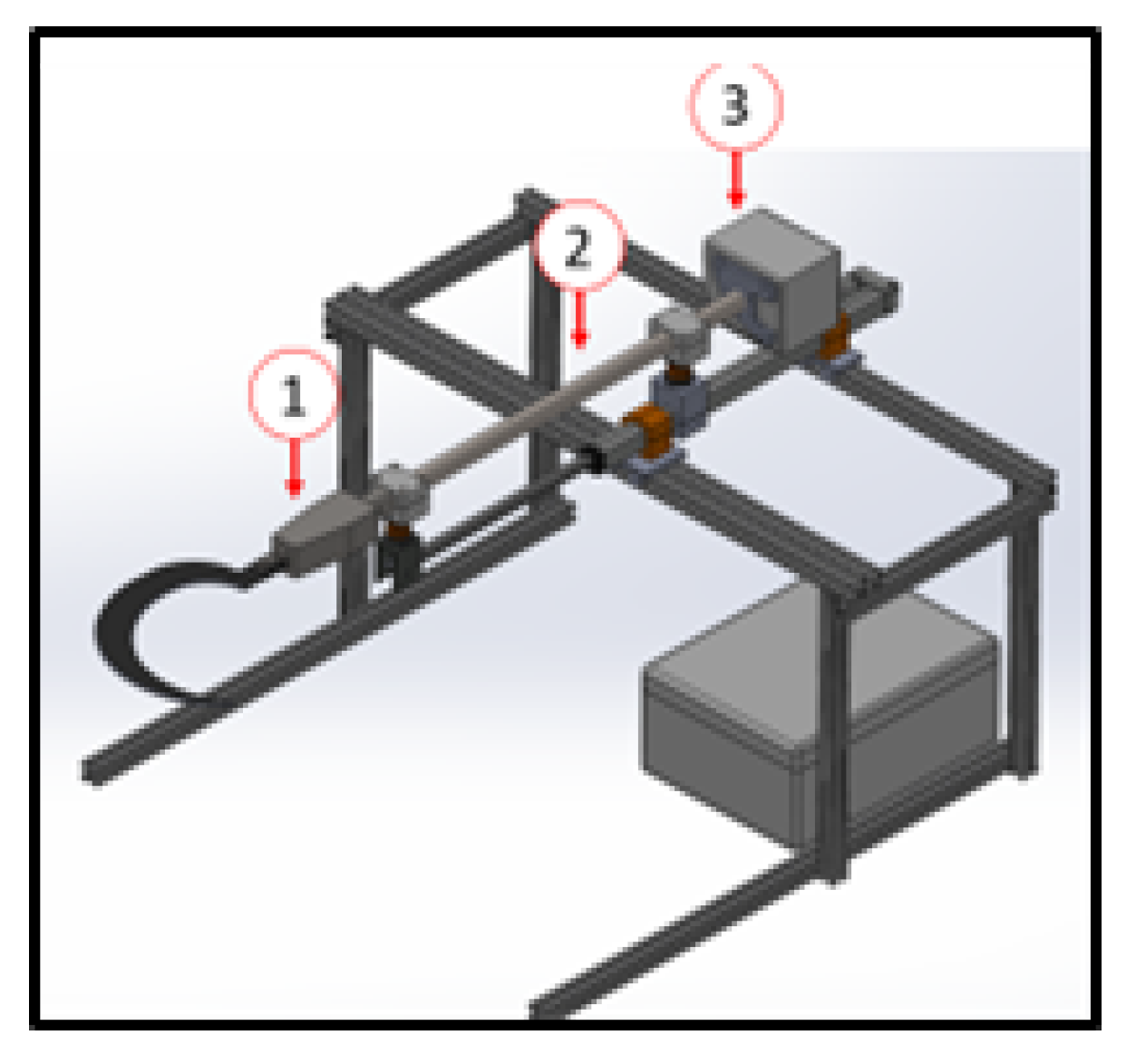
The brushless motor used has three speed variables: 5700 rpm, 8200 rpm, and 9700 rpm. Testing is conducted on three types of attachments: chainsaw, dodos, and egrek. Each attachment will be operated at the three speeds for 5 seconds to observe the vibration levels at three measurement points: gearbox (area point 1), shaft pole (area point 2), and the driving motor (area point 3). The test results will display various vibration values, and the lowest vibration value will indicate the most suitable attachment for use on the drone.
4. Result and Analysis
4.1.1. Displacement Reading on the Chainsaw Cutting System
Based on the experiment conducted on the chainsaw cutting system at three different brushless motor speed variations 5700 rpm, 8200 rpm, and 9700 rpm. the displacement values obtained from the trials are presented in Table 4 below.
Table 4 presents the results of displacement measurements on the chainsaw cutting system with variations in brushless motor speeds across different areas. Based on these measurements, a graph illustrating the relationship between motor rotational speed and displacement at various points is generated, as shown in.
Figure 10 illustrates the displacement data for the chainsaw cutting system, measured in millimeters (mm) at three points across different motor speeds: 5700 RPM, 8200 RPM, and 9700 RPM. At 5700 RPM, the displacement at area point 1 was 0.031 mm, at area point 2 was 0.079 mm, and at area point 3 was 0.094 mm, resulting in an average displacement of 0.068 mm. At 8200 RPM, the displacement at area point 1 was 0.028 mm, at area point 2 was 0.063 mm, and at area point 3 was 0.175 mm, yielding an average displacement of 0.089 mm. Finally, at 9700 RPM, the displacement at area point 1 was 0.034 mm, at area point 2 was 0.066 mm, and at area point 3 was 0.232 mm, with an average displacement of 0.111 mm. These results indicate that the average displacement of the chainsaw increases with higher motor speeds, particularly at area point 3, which consistently shows the highest displacement values across all speeds.
4.1.2. Displacement Reading on the Dodos Cutting System
Based on the experiment on the dodos cutting system at each of the three motor speed variations of 5700 RPM, 8200 RPM, and 9700 RPM, the displacement values from the experiment can be seen in Table 5 below.
Table 5 shows the results of the displacement measurements for the chainsaw with variations in brushless motor speeds at different measurement points. Based on the measurement results, the data is presented in a graph of motor speed versus various measurement points, as shown in Figure 11.
Figure 11 shows the displacement data for the dodos cutting system at three measurement points across different motor speeds: 5700 RPM, 8200 RPM, and 9700 RPM. At 5700 RPM, the displacement at area point 1 was 0.644 mm, at area point 2 was 0.838 mm, and at area point 3 was 0.873 mm, resulting in an average displacement of 0.785 mm. At 8200 RPM, the displacement at area point 1 was 1.417 mm, at area point 2 was 2.500 mm, and at area point 3 was 2.557 mm, yielding an average displacement of 2.158 mm. Finally, at 9700 RPM, the displacement at area point 1 was 1.800 mm, at area point 2 was 2.600 mm, and at area point 3 was 2.612 mm, with an average displacement of 2.337 mm. The data shows that the average displacement of the dodos cutting system increases with higher motor speeds (RPM). Area points 2 and 3 exhibit larger displacement values than area point 1 at every speed, indicating that higher speeds result in greater displacement in the dodos cutting system.
4.1.3. Displacement Reading on the Egrek Cutting System
Based on the experiment on the egrek cutting system at each of the three motor speed variations of 5700 RPM, 8200 RPM, and 9700 RPM, the displacement values from the experiment can be seen in Table 6 below.
Table 6 shows the results of the displacement measurements for the egrek with variations in brushless motor speeds at different measurement points. Based on the measurement results, the data is presented in a graph of motor speed versus various measurement points, as shown in Figure 12.
Figure 12 shows the displacement data for the egrek cutting system in millimeters (mm) at three measurement points across different motor speeds: 5700 RPM, 8200 RPM, and 9700 RPM. At 5700 RPM, the displacement at area point 1 was 0.650 mm, at area point 2 was 0.832 mm, and at area point 3 was 0.882 mm, with an average displacement of 0.788 mm. At 8200 RPM, the displacement at area point 1 was 1.422 mm, at area point 2 was 2.500 mm, and at area point 3 was 2.558 mm, resulting in an average displacement of 2.160 mm. At the highest speed of 9700 RPM, the displacement at area point 1 was 1.811 mm, at area point 2 was 2.620 mm, and at area point 3 was 2.661 mm, with an average displacement of 2.364 mm. These results indicate that the average displacement in the egrek cutting system increases with higher motor speeds (RPM). Area points 2 and 3 show greater displacement than area point 1 at all speeds, indicating that higher speeds result in larger displacements in the egrek cutting system.
4.1.4. Comparison of Average Displacement on the Cutting System Using Chainsaw, Dodos, and Egrek
Table 7 shows the results of the displacement measurements for the egrek with variations in brushless motor speeds at different measurement points. Based on the measurement results, the data is presented in a graph of motor speed versus various measurement points, as shown in Figure 13
Figure 13 shows the average displacement values for three types of cutting systems—chainsaw, dodos, and egrek—at different motor speeds: 5700 RPM, 8200 RPM, and 9700 RPM. At 5700 RPM, the average displacement for the chainsaw was recorded at 0.068 mm, while the dodos and egrek reached 0.785 mm and 0.788 mm, respectively. At 8200 RPM, the average displacement for the chainsaw increased to 0.089 mm, while the dodos reached 2.158 mm and the egrek 2.160 mm. At the highest speed of 9700 RPM, the average displacement for the chainsaw was 0.111 mm, with the dodos reaching 2.337 mm and the egrek 2.364 mm. This data shows that the average displacement for the dodos and egrek is much higher than the chainsaw at all speeds. Additionally, all tools demonstrated an increase in displacement as the motor speed increased, with the dodos and egrek having higher displacement values than the chainsaw at every measured speed
4.2. Analiysis
Based on the analysis of the average displacement graph at various speeds, there are significant differences in the vibration levels produced by each cutting tool: Chainsaw, Dodos, and Egrek. The displacement in the Chainsaw is much smaller compared to the Dodos and Egrek, indicating differences in the characteristics and mechanisms of each tool.
The Chainsaw has low displacement at all speeds. This is due to the gearbox mechanism, which directly transmits power through gears. This direct transmission system allows the Chainsaw to generate a more stable and minimal displacement, resulting in consistently low displacement values across all speed variations.
In contrast, both the Dodos and Egrek show a significant increase in displacement as the speed increases. The larger displacement in these tools is due to the crank mechanism, which converts the rotational motion of the motor into linear motion. This crank mechanism results in higher displacement, especially at higher speeds, due to the back-and-forth motion produced by the mechanism. Although the displacement difference between the Dodos and Egrek is not very significant, the relatively larger cutting tool of the Egrek slightly contributes to this difference.
5. Conclusions
There is a direct relationship between the increase in RPM and displacement in the chainsaw, dodos, and egrek cutting systems. As the RPM increases, the displacement becomes larger in all three components. However, the chainsaw cutting system shows smaller displacement values compared to the dodos and egrek systems. The chainsaw demonstrates relatively smaller displacement, indicating that the chainsaw cutting system has a higher level of stability when mounted on a drone.
References
- Lubis, Hakim A. Design of Test Equipment for Cutting Oil Palm Fronds Using Enggrek at Various Tilt Angles. Jurnal Engineering Development 2021, 1(2), 72–79. [Google Scholar]
- Purnama, H.; Afrillah, M. Growth Analysis of Seeds Oil Palm on Stage Pre Nursery and Main Nursery At PT. SOCFINDO. DEVOTION 2022, 3. [Google Scholar] [CrossRef]
- Stella, *!!! REPLACE !!!*; Ginting, B.; Saidin, O. K. and Azwar, T. K. D. Oil palm industry digitalization for sustainable plantation production in community economic development. IOP Conf. Series: Earth and Environmental Science 2020, 782. [Google Scholar] [CrossRef]
- Suroso, A. I.; Tandra, H.; Najib, M. and Syaukat, Y. Firm Performance Factors and Efficiency of Indonesian Palm Oil. Jurnal Manajemen & Agribisnis 2020. [Google Scholar]
- Teresia, V.; and Lestari, D. I.T. Analysis of Work Posture on Complaints of Musculoskeletal Disorders in Oil Palm Harvester Workers. Tarumanagara Medical Journal 2022, 4(2), 352–359. [Google Scholar] [CrossRef]
- Uragoda, C.G. An investigation into the health of kapok workers. Br J Ind Med 1977, 181. [Google Scholar] [CrossRef]
- Assadi, SN. Carrying Load and Related Health Disorders and Disability. Indian J Occup Environ Med 2022, 352, 129–132. [Google Scholar] [CrossRef]
- Raj, M.; Harshini, N. B.; Gupta, S.; Atiquzzaman, M. and Rawlley, Oshin. Leveraging precision agriculture techniques using UAVs and emerging disruptive technologies. Energy Nexus 2024, 14. [Google Scholar] [CrossRef]
- Anbumozhi, A.; Shanthini, A. Adoption of Novel Technologies to Boost Precision Agriculture (BPA) using Internet of Things (IOT). ITM Web of Conferences 2023. [Google Scholar] [CrossRef]
- Khuzaimah, Z.; Nawi, N. M.; Adam, S. N.; Kalantar, Emeka, O. J.; Ueda, N. Application and Potential of Drone Technology in Oil PalmPlantation: Potential and Limitations. Journal of Sensors 2022. [Google Scholar] [CrossRef]
- Get to Know the Oil Palm Tree and its Characteristics. Available online: https://palmoilina.asia/sawit-hub/pohon-kelapa-sawit/ (accessed on 10 October 2023).
- Bakewell-Stone, Petra. Elaeis guineensis (African oil palm) CAB Internation 2023.
- Wahab, R.; Rasat, M. S. M.; Fauzi, N. M.; Sulaiman, M. S.; Samsi, H. W.; Mokhtar, N.; Ghani, R. S. M.; and Razak, M. H. Processing and Properties of Oil Palm Fronds Composite Boards from Elaeis guineensis. Elaeis Guineensis 2021. [Google Scholar]
- Song, Y.; Martin, J. J. J.; Liu, X.; Li, X.; Hou, M.; Zhang, R.; Xu, W.; Li, W. and Cao H. Unraveling the response of secondary metabolites to cold tolerance in oil palm by integration of physiology and metabolomic analyses. BMC Plant Biology 2025, 25. [Google Scholar] [CrossRef] [PubMed]
- Mosquera-Montoya, M.; Martínez, D. E. M.; Álvarez, E. R.; Fontanilla-Díaz, C. A.; Salamanca, O. H.; Esguerra, J. M. O. Labor productivity assessment of three different mechanized harvest systems in Colombian oil palm crops. OCL 2023, 30. [Google Scholar] [CrossRef]
- Torres Ortega, R.; Luna Velasco, M.; Arrieta Baldovino, J. Characterization of the Pozzolanic Potential of Oil Palm Kernel Shell Ash Obtained Through Optimization of Physicochemical Processes. Materials 2025, 18, 1248. [Google Scholar] [CrossRef]
- Torres-Ortega, R.; Torres-Sánchez, D.; Saba, M. Impact of Physical Processes and Temperatures on the Composition, Microstructure, and Pozzolanic Properties of Oil Palm Kernel Ash. ChemEngineering 2024, 8, 122. [Google Scholar] [CrossRef]
- Ahirwar, S.; Swarnkar, R.; Bhukya, S.; and Namwade, G. Application of Drone in Agriculture. Int J Curr Microbiol Appl Sci 2019, 8. [Google Scholar] [CrossRef]
- Unmanned Aerial Vehicle. Available online: https://www.britannica.com/technology/unmanned-aerial-vehicle (accessed on 24 July 2025).
- Rizki, H. Modification of Lawn Mower into Palm Oil Harvesting Tool. Diploma, Universitas Andalas Elaeis Guineensis 2018.
- Hamsi, A.; Sitorus, T. B.; Isma, T.B. Design assembling and testing of the oil palm bunches cutting machines. IOP Conference Series 2020, 1003. [Google Scholar] [CrossRef]
- How Does a Linear Actuator work? Available online: https://www.firgelliauto.com/blogs/actuators/how-does-a-linear-actuator-work-1 (accessed on 24 July 2025).
- Electric Linear Actuators Explained. Available online: https://www.tolomatic.com/blog/how-does-a-linear-actuator-work/ (accessed on 24 July 2025).
- Altiner, B.; Delibasi, A.; Erol, B. Modeling and control of flexible link manipulators for unmodeled dynamics effect. Proceedings of the Institution of Mechanical Engineers, Part I : Journal of Systems and Control Engineering 2018, 233, 245–263. [Google Scholar] [CrossRef]
- Pustavrh, J.; Hočevar, M.; Podržaj, P.; Trajkovski, A.; and Majdic, F. Comparison of hydraulic, pneumatic and electric linear actuation systems. Sci Rep 2023, 13. [Google Scholar] [CrossRef]
- Ekeocha, R. J. O. Modeling and control of flexible link manipulators for unmodeled dynamics effect. Journal of Mechanical Engineering Research 2017, 10. [Google Scholar]
- Vibration in Mechanical Engineering The Good and The Bad. Available online: https://www.discoverengineering.org/vibration-in-mechanical-engineering-the-good-and-the-bad/ (accessed on 24 July 2025).
- Jiang, X.; Li, Z.; Wang, Y.; Pan, F. Self-loosening behavior of bolt in curvic coupling due to materials ratcheting at thread root. Advances in Mechaninal 2019, 11. [Google Scholar] [CrossRef]
- Bickford, John H. Introduction to the Design and Behavior of Bolted Joints, 4th ed.; CRC Press: Routledge, 2007. [Google Scholar]
- Jiang, Y.; Zhang, M.; Park, T.-W.; and Lee, C.-H. An Experimental Study of Self-Loosening of Bolted Joints. Journal of Mechanical Design – J MECH DESIGN 2004, 126. [Google Scholar] [CrossRef]
Figure 1.
Research diagram flow.
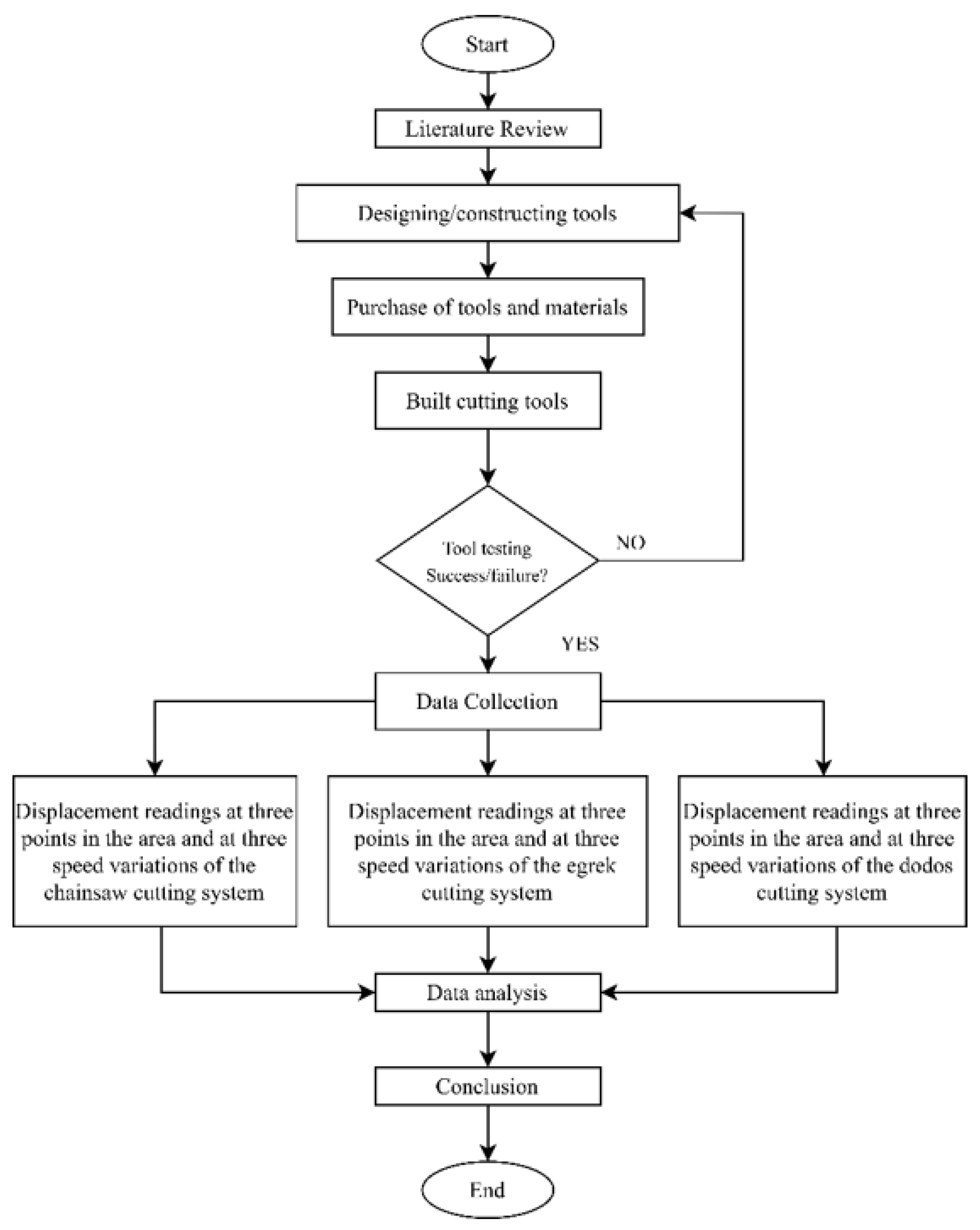
Figure 3.
Research diagram flow.
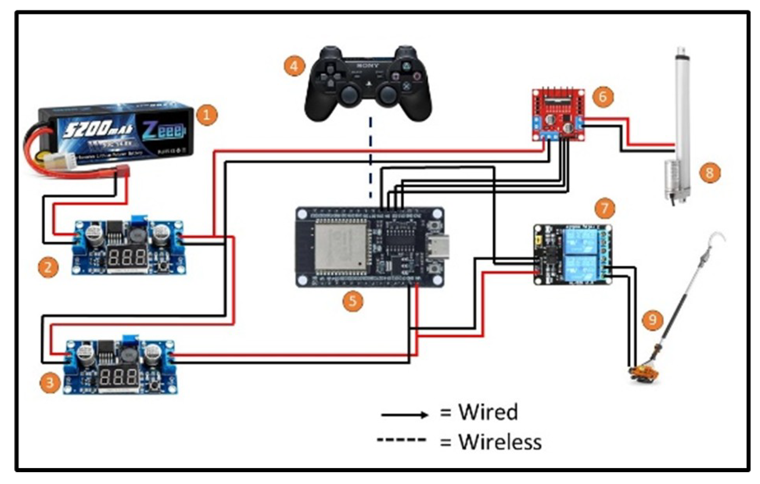
Figure 4.
Flowchart of the cutting system program.
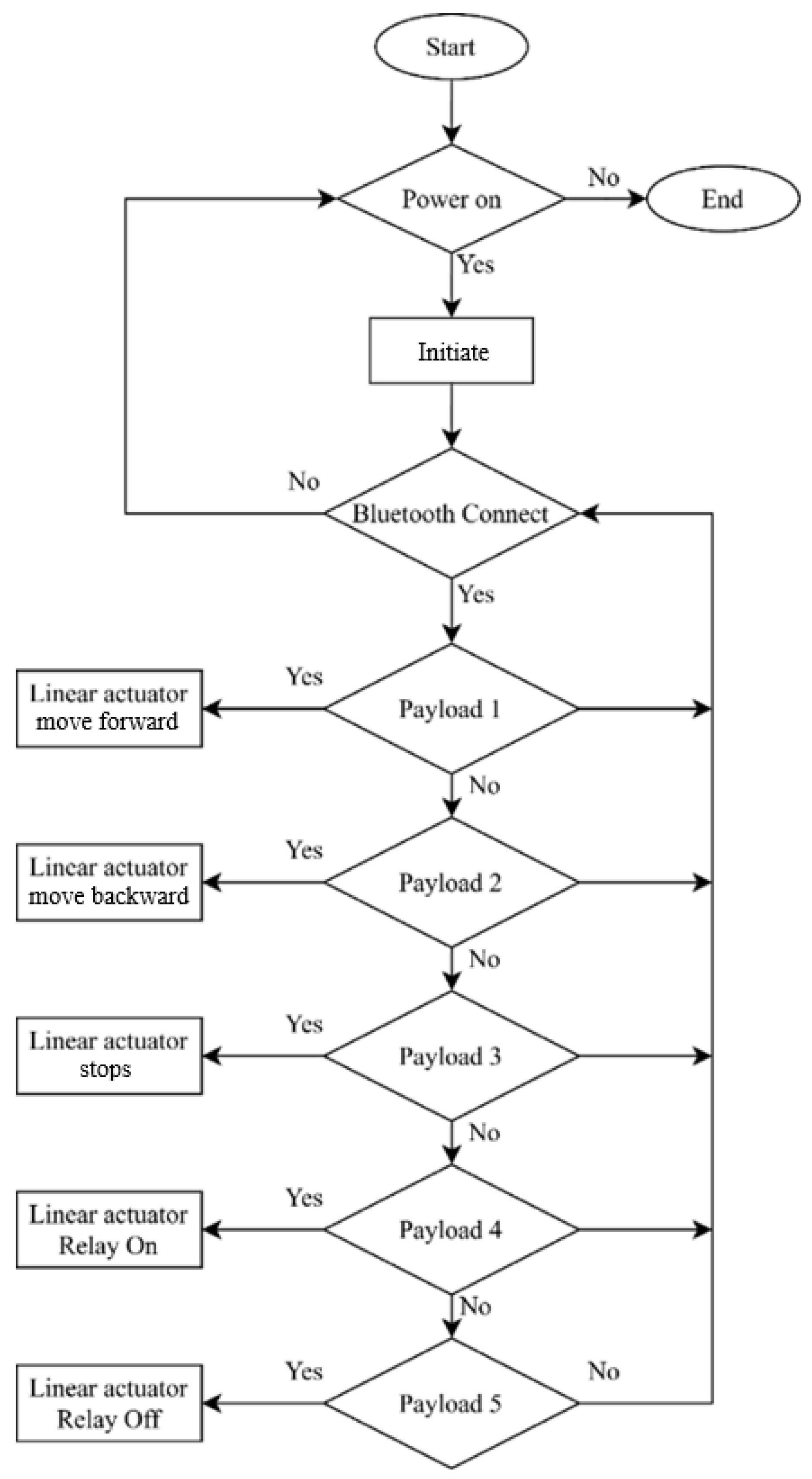
Figure 10.
Graph of Displacement Levels in the Cutting System Using Chainsaw Across Various Area Points with Speed Variations.
Figure 10.
Graph of Displacement Levels in the Cutting System Using Chainsaw Across Various Area Points with Speed Variations.
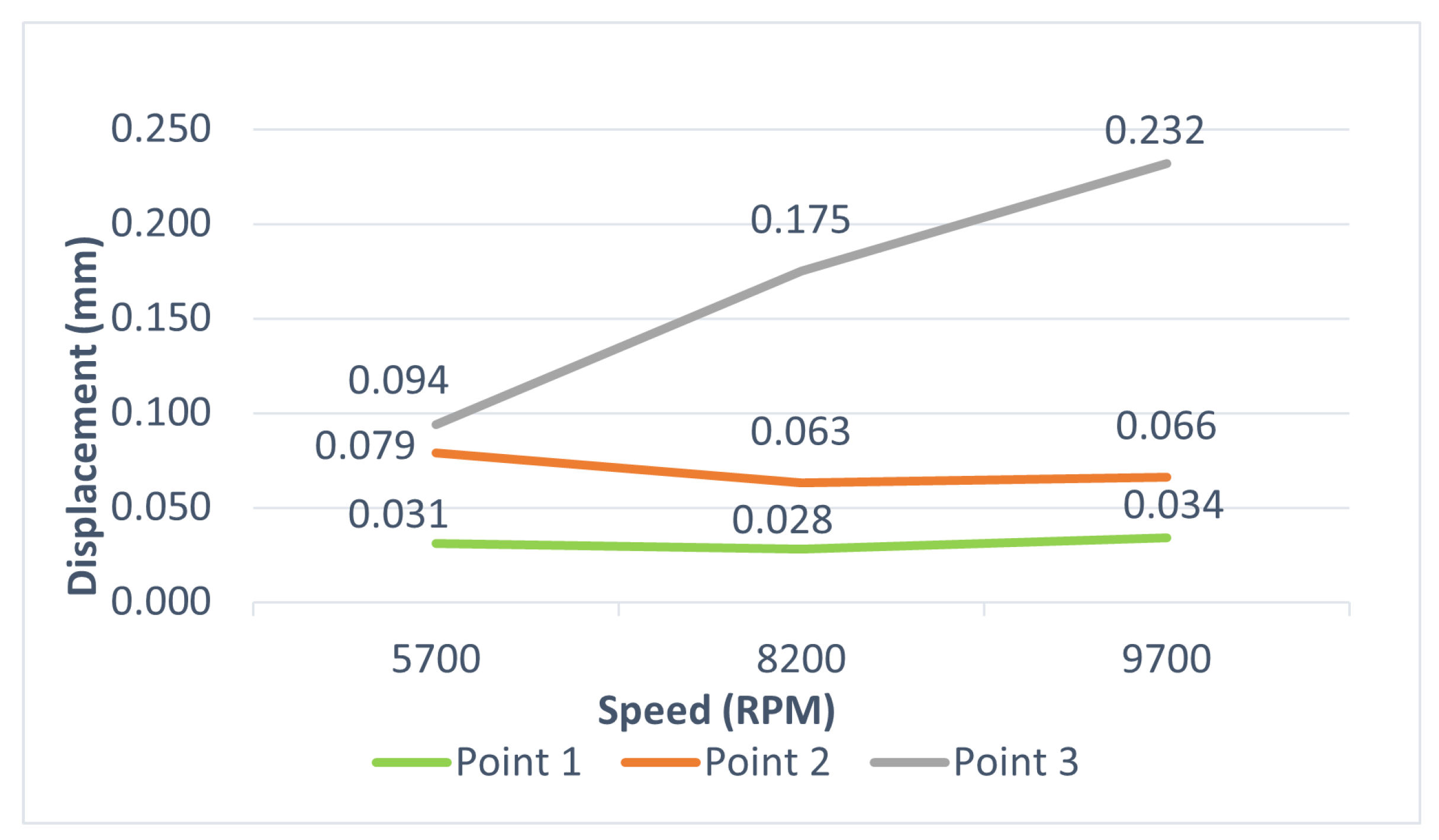
Figure 11.
Graph of Displacement Levels in the Cutting System Using Dodos Across Various Area Points with Speed Variations.
Figure 11.
Graph of Displacement Levels in the Cutting System Using Dodos Across Various Area Points with Speed Variations.
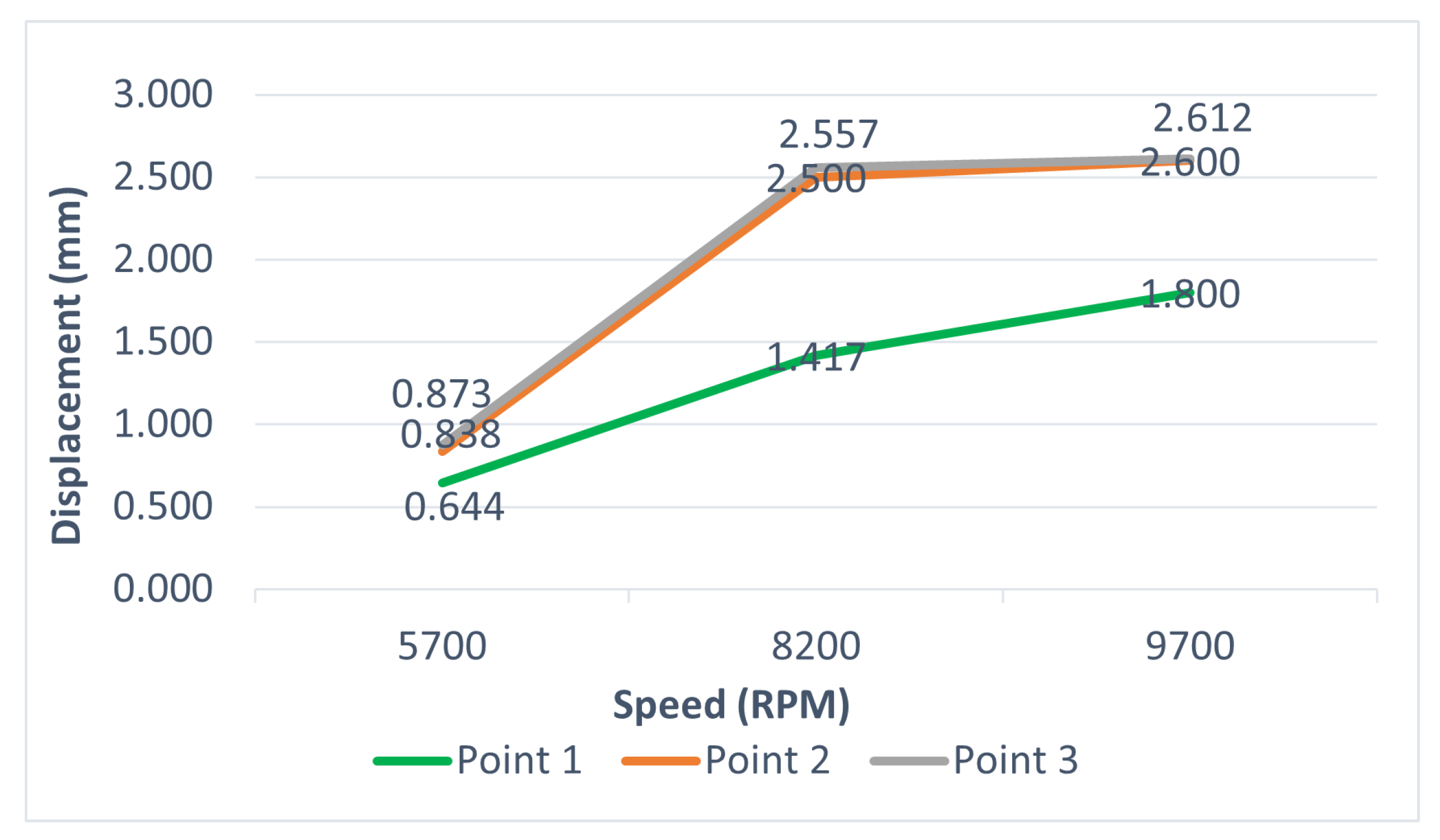
Figure 12.
Graph of Displacement Levels in the Cutting System Using Egrek Across Various Area Points with Speed Variations.
Figure 12.
Graph of Displacement Levels in the Cutting System Using Egrek Across Various Area Points with Speed Variations.
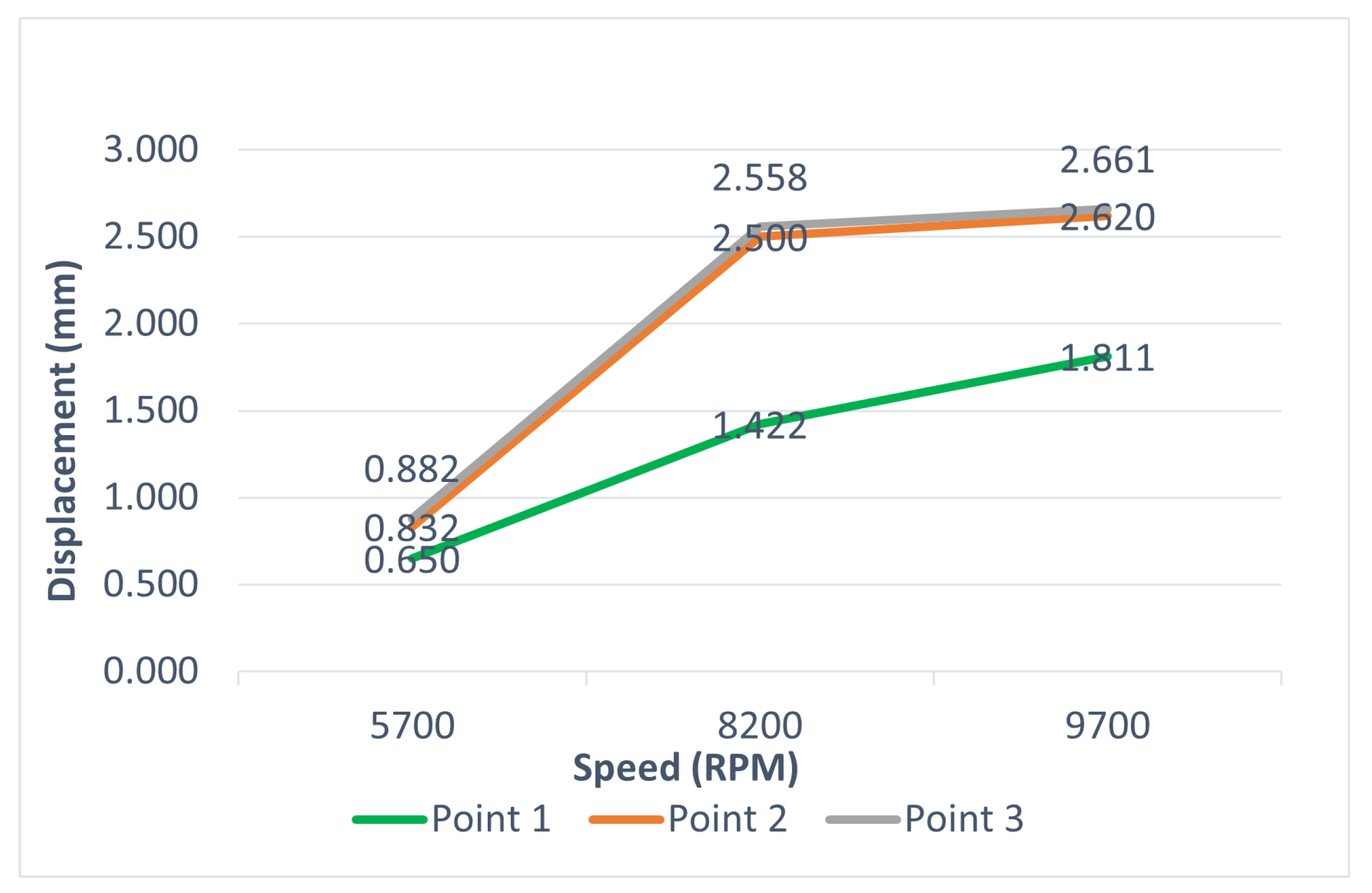
Figure 13.
Graph Comparing the Average Vibration Levels Across Different Oil Palm Cutting Systems with Speed Variations.
Figure 13.
Graph Comparing the Average Vibration Levels Across Different Oil Palm Cutting Systems with Speed Variations.
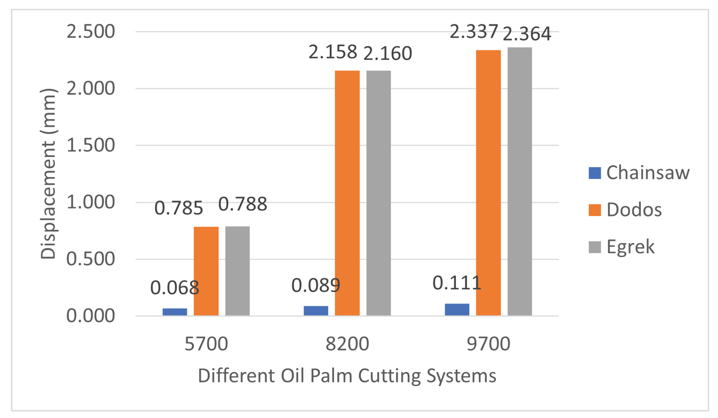
Table 4.
The Displacement values that occur on the Chainsaw cutting system.
| Speed | Chainsaw Displacement value (mm) | |||
|---|---|---|---|---|
| (RPM) | area point 1 | area point 2 | area point 3 | Average |
| 5700 | 0.031 | 0.079 | 0.094 | 0.068 |
| 8200 | 0.028 | 0.063 | 0.175 | 0.089 |
| 9700 | 0.034 | 0.066 | 0.232 | 0.111 |
Table 5.
The Displacement values that occur on the dodos cutting system.
| Speed | Dodos Displacement value (mm) | |||
|---|---|---|---|---|
| (RPM) | area point 1 | area point 2 | area point 3 | Average |
| 5700 | 0.644 | 0.838 | 0.873 | 0.785 |
| 8200 | 1.417 | 2.500 | 2.557 | 2.158 |
| 9700 | 1.800 | 2.600 | 2.612 | 2.337 |
Table 6.
The Displacement values that occur on the egrek cutting system.
| Speed | Egrek Displacement value (mm) | |||
|---|---|---|---|---|
| (RPM) | area point 1 | area point 2 | area point 3 | Average |
| 5700 | 0.650 | 0.832 | 0.882 | 0.788 |
| 8200 | 1.422 | 2.500 | 2.558 | 2.160 |
| 9700 | 1.811 | 2.620 | 2.661 | 2.364 |
Table 7.
The average displacement values for the variation in cutting systems.
| Speed | The average Displacement values. (m/s2) | ||
|---|---|---|---|
| (RPM) | Chainsaw | Dodos | Egrek |
| 5700 | 0.068 | 0.785 | 0.788 |
| 8200 | 0.089 | 2.158 | 2.160 |
| 9700 | 0.111 | 2.337 | 2.364 |
Disclaimer/Publisher’s Note: The statements, opinions and data contained in all publications are solely those of the individual author(s) and contributor(s) and not of MDPI and/or the editor(s). MDPI and/or the editor(s) disclaim responsibility for any injury to people or property resulting from any ideas, methods, instructions or products referred to in the content. |
© 2025 by the authors. Licensee MDPI, Basel, Switzerland. This article is an open access article distributed under the terms and conditions of the Creative Commons Attribution (CC BY) license (http://creativecommons.org/licenses/by/4.0/).
Copyright: This open access article is published under a Creative Commons CC BY 4.0 license, which permit the free download, distribution, and reuse, provided that the author and preprint are cited in any reuse.


