Submitted:
26 July 2025
Posted:
28 July 2025
You are already at the latest version
Abstract
This paper presents the design, modeling, and experimental validation of a magnetically levitated hydrokinetic micro-turbine optimized for ultra-low-flow streams (Q < 0.1 m3/s). The proposed system integrates high-temperature superconducting (HTS) bearings to eliminate mechanical contact and frictional losses, enabling efficient energy conversion in remote, low-head environments. A coupled CFD–FEA modeling framework is developed to predict system dynamics, efficiency, and rotor dynamic stability under variable flow conditions. Simulation and prototype measurements reveal a peak hydraulic-to-electrical conversion efficiency of (82.4%) and excellent agreement with predicted torque-speed and thermal profiles. Dynamic testing confirms rapid startup, stable thermal regulation, and negligible vibration modes due to HTS-based damping. A detailed techno-economic analysis indicates a levelized cost of energy (LCOE) of $0.094/kWh over a 20-year lifetime, outperforming diesel and solar-battery alternatives in both cost and reliability for rural electrification. Sensitivity assessments show that performance is robust to variations in cryogenic load and capital expenditure. The findings establish superconducting micro-hydropower as a viable and sustainable solution for off-grid energy access in hydrologically stable but hydraulically constrained settings.
Keywords:
Cryogenic Cooling
; High-Temperature Superconductors
; Hydrokinetic Micro-Turbine
; Magnetic Levitation
; Rural Electrification
1. Introduction
1.1. Small-Stream Hydropower Potential and Limitations
Small-stream hydropower, typically characterized by annual mean flow rates below 0.1 m3/s, constitutes a widely underexploited renewable energy resource, particularly in rural, mountainous, and off-grid communities [1]. Unlike large-scale hydropower, which depends on significant infrastructure and substantial head, small streams offer a decentralized solution with minimal environmental disruption. However, despite the abundance of these sites, their practical deployment remains limited.
The primary challenge lies in the poor hydraulic coupling and low power density associated with microflow regimes. Conventional flow-of-river or impulse-type systems exhibit significant drops in efficiency under such conditions, often due to mismatch between available flow energy and turbine design parameters [2]. Moreover, the levelized cost of energy (LCOE) in these low-resource settings is often prohibitively high, rendering the majority of micro-stream sites economically non-viable under traditional design paradigms.
1.2. Frictional Losses and Mechanical Wear in Conventional Turbines
Mechanical losses constitute a significant barrier to the efficiency and longevity of micro-hydro turbines. In particular, friction from mechanical bearings can account for up to 25% of total input power losses at low speeds, a figure which becomes especially critical in systems operating under sub-kilowatt loads [3]. Additionally, bearing wear, exacerbated by exposure to sediment, vibration, and thermal cycling, leads to frequent maintenance requirements and reduced operational lifetimes [4]. These issues not only degrade system performance but also undermine the financial and logistical viability of deploying small-scale hydro systems in remote locations where skilled maintenance personnel and spare parts are often unavailable.
1.3. Magnetic Levitation and High-Temperature Superconducting Bearings
Magnetic levitation offers a promising solution to mitigate frictional and mechanical wear. Unlike traditional contact bearings, magnetic bearings provide non-contact support, enabling ultra-low friction operation and eliminating lubrication requirements. Active magnetic bearings (AMBs) and permanent magnet bearings (PMBs) have been demonstrated in wind and flywheel systems; however, their implementation is limited by either complexity (AMBs) or load instability (PMBs) [5].
Recent breakthroughs in high-temperature superconducting (HTS) materials, such as yttrium barium copper oxide (YBCO), have enabled the development of flux-pinning magnetic bearings capable of stable levitation at cryogenic temperatures ( 77 K). These HTS bearings provide inherently passive stabilization and have been shown to support substantial loads with virtually zero mechanical drag. Experimental studies report over 30% reductions in parasitic losses when compared to conventional electromagnetic systems, making HTS a viable platform for micro-scale turbines in energy-constrained environments [6].
1.4. Scope, Contributions, and Paper Organization
This paper presents a novel hydrokinetic turbine architecture that integrates high temperature superconducting magnetic levitation to enable efficient power generation from ultra-low-flow streams. Specifically, the proposed system is designed to achieve hydraulic-to-electrical conversion efficiencies exceeding 80% for flows below 0.1 m3/s, with negligible mechanical wear and reduced maintenance overhead.
Section II presents a comprehensive review of existing low-flow turbine designs and magnetic bearing technologies. Section fIII formulates the optimization problem governing turbine performance. Section IV describes the system architecture, bearing configuration, and multiphysics modeling framework. Section V outlines the simulation workflow and experimental setup, followed by performance results and techno-economic analysis in Sections fVI and VII, respectively. Finally, Section VIII concludes the paper with a summary of findings and directions for future research.
2. Literature Review
2.1. Hydrokinetic Turbine Designs for Low-Flow Sites
The development of hydrokinetic turbines for low-flow regimes () presents unique challenges in achieving high energy conversion efficiency while maintaining simplicity, cost-effectiveness, and ecological compatibility. Several turbine topologies have been explored to harness energy from such ultra-low discharge environments.
Cross-flow turbines have demonstrated effective operation in the flow range of 0.05–0.2 m3/s with peak efficiencies up to 65%, though performance is limited by secondary vortex-induced losses and structural complexity [7]. Archimedes screw turbines, by contrast, offer fish-friendly characteristics and moderate efficiencies ( 70%) at flow rates as low as 0.02 m3/s, but require substantial civil infrastructure and have a lower power density [8]. Micro Pelton wheels, while highly efficient (up to 75%) at extremely low flows ( 0.01 m3/s), necessitate high head conditions and precise jet-nozzle control [9].
Oscillating water columns (OWCs) and impulse-type Turgo turbines have also been explored for low-head and low-flow scenarios, offering moderate efficiencies with simpler mechanical components and acceptable robustness to debris and sediment loads [10,11]. A comparative summary of key performance metrics is provided in Table 1.
These existing designs underscore the trade-offs inherent to low-flow energy conversion, particularly the balance between mechanical complexity, environmental compatibility, and achievable efficiency.
2.2. Magnetic Bearing Technologies in Renewable Energy Systems
Magnetic bearings have emerged as a compelling alternative to conventional mechanical supports in renewable energy applications due to their ability to eliminate contact-induced friction and wear. Two primary categories dominate the literature: active magnetic bearings (AMBs) and passive magnetic bearings (PMBs).
AMBs utilize real-time control to stabilize rotor position and offer high precision, but at the cost of continuous electrical power draw and complex feedback systems [17,18]. PMBs, while inherently energy-efficient, suffer from limited dynamic stiffness and stability due to the Earnshaw instability theorem [19].
High-temperature superconducting (HTS) bearings represent a third category, exploiting the flux-pinning effect in YBCO ceramics to enable passive, self-stabilizing levitation with negligible power consumption. Laboratory-scale demonstrations of HTS bearings in flywheel energy storage systems have shown parasitic drag reductions of over 30%, with no observable wear over thousands of operational cycles [20]. Despite these advantages, their application to hydrokinetic turbines remains relatively unexplored, particularly in submerged, variable-flow environments.
2.3. High-Temperature Superconductors in Rotordynamics
The use of HTS materials in rotordynamic systems has seen growing interest in recent years. Bulk YBCO disks operating at cryogenic temperatures () have demonstrated lift forces exceeding 5 kN per module [21]. Experimental work has confirmed that these bearings maintain mechanical stiffness and damping over extended thermal cycling, with less than 5% deviation in levitation force after 1000 cycles [22].
Finite element modeling studies that integrate electromagnetic field simulations with rotor-dynamic solvers predict high modal stiffness and resonance-free operation up to 10,000 rpm in micro-scale rotor assemblies [23]. However, practical deployment of HTS systems in fluid environments raises new challenges, such as cryogenic containment, thermal insulation under submerged conditions, and potential degradation due to biofouling or sediment accumulation.
2.4. Research Gaps in Small-Scale Hydrokinetic Systems
While the literature offers foundational insights into both low-flow turbine design and magnetic levitation, several critical research gaps remain unaddressed:
- Comprehensive Loss Characterization: Few studies provide a detailed breakdown of parasitic losses, including magnetic hysteresis, aerodynamic drag, and cryogenic cooling power, in HTS-levitated hydrokinetic systems [24].
- Field-Deployable Prototypes: Most existing research on HTS bearings is limited to laboratory-scale, dry-environment applications. There is a notable lack of validated field trials in real watercourses with variable flow and environmental contaminants [25].
- Economic Feasibility and LCOE Modeling: Lifecycle cost assessments incorporating the capital and operational expenditures of cryogenic subsystems, maintenance intervals, and grid integration remain scarce [26].
- Ecological and Environmental Effects: The implications of operating submerged superconducting modules in natural habitats, including potential thermal plumes, interactions with aquatic life, and long-term material durability, are yet to be comprehensively explored.
These limitations underscore the need for an integrated research approach combining multiphysics modeling, experimental validation, and techno-economic assessment. The present work aims to bridge these gaps by developing, modeling, and validating a magnetically levitated micro-turbine tailored for low-flow environments using HTS bearings.
3. Problem Formulation and Research Objectives
3.1. Mathematical Statement of the Optimization Problem
The performance of the proposed magnetically levitated hydrokinetic turbine depends on both fluid–mechanical and electromechanical interactions, as well as the thermal behavior of the HTS subsystem. To formalize the design trade-offs, we define the following variables:
- Q [m3/s]: volumetric flow rate entering the turbine;
- [rad/s]: rotor angular velocity;
- H [m]: net hydraulic head at the site;
- [kg/m3]: water density;
- g [m/s2]: gravitational acceleration;
- [W]: cryogenic cooling power required to maintain HTS stability;
- [-]: hydraulic-to-electrical conversion efficiency;
- [W]: total parasitic losses, where
To maximize the system’s net energy conversion, we define a normalized objective function , which penalizes efficiency losses due to both mechanical and thermal parasitics:
where is a weighting parameter that reflects the relative importance of minimizing parasitic consumption in low-resource environments.
The optimization problem is then expressed as:
Where [N] is the radial load on the HTS bearing as a function of flow rate and rotor speed; [N] denotes the maximum allowable load based on the flux-pinning capacity of the superconductor; [K] is the steady-state operating temperature of the HTS subsystem; [K] represents the critical temperature of the superconducting material (typically 93 K for YBCO); and [rad/s] define the safe operational speed envelope for the rotor; and and [m3/s] correspond to the site-constrained minimum and maximum allowable volumetric flow rates.
3.2. Performance Metrics and Success Criteria
To evaluate the system’s viability in real-world deployment, we introduce the levelized cost of energy (LCOE) as the primary economic metric:
where:
and is the expected operational lifetime of the system.
Based on the target application of distributed, off-grid power generation, the following performance thresholds are established as success criteria:
- Achieve across the operating range m3/s;
- Ensure total parasitic and cooling losses satisfy:
- Attain over a 20-year system lifetime.
3.3. Research Objectives
Guided by the above formulation, the principal objectives of this study are:
- To develop coupled computational models (CFD and FEA) for accurately predicting hydrodynamic performance and parasitic losses;
- To fabricate and experimentally validate a laboratory-scale prototype under variable flow and load conditions;
- To conduct a techno-economic analysis, including LCOE estimation based on empirical performance data and site-adapted flow scenarios.
This formulation provides a comprehensive basis for evaluating the feasibility and scalability of magnetically levitated hydrokinetic systems in small-stream energy harvesting applications.
4. System Design and Modeling
4.1. Overall Turbine Architecture
The proposed magnetically levitated hydrokinetic micro-turbine is designed to operate efficiently in ultra-low flow environments. Its modular architecture comprises four core subsystems, as illustrated in Figure 1:
- Inlet Nozzle and Flow Conditioner: Guides ambient streamwater into a collimated axial jet to maximize energy density at the runner.
- Runner and Rotor Blades: Transduces kinetic energy from the flow into rotational torque using a blade geometry optimized via blade-element theory.
- HTS Bearing and Cryocooling Subsystem: Provides contactless, frictionless rotor support at cryogenic temperatures () using flux-pinning effects from YBCO superconductors.
- Permanent Magnet Synchronous Generator (PMSG): Converts mechanical power into three-phase electrical output, regulated via inverter-based power electronics.
4.2. HTS Bearing Configuration and Magnetic Suspension Modeling
To eliminate mechanical wear, the rotor is levitated using high-temperature superconducting (HTS) bearings composed of YBCO bulks magnetically coupled to a Halbach array. The flux-pinning phenomenon enables passive stabilization. The restoring stiffness and damping coefficient in the radial direction are derived from the second and first derivatives of the magnetic potential energy , respectively:
where x is the radial displacement, and is an empirically derived damping factor representing hysteretic energy loss.
The equilibrium bearing load is modeled as:
which must satisfy the mechanical constraint , where is the flux-pinning load limit of the YBCO material.
4.3. Runner Geometry and Blade Element Momentum Theory
The hydrokinetic energy conversion is achieved via a custom-designed axial-flow runner consisting of blades. Each blade is defined by a spanwise chord distribution and twist angle over radius . Based on Blade Element Momentum (BEM) theory, the infinitesimal torque contribution from an annular element at radius r is:
where is the lift coefficient, and the angle of attack is defined by , with
as the local inflow angle. The total runner torque is obtained by integrating over the entire blade span:
4.4. Electromechanical Generator and Inverter Modeling
The electrical subsystem consists of a low-speed permanent magnet synchronous generator (PMSG). The stator equations in the synchronous -reference frame are expressed as:
Where and denote the stator voltages in the d- and q-axes, respectively; and are the corresponding axis currents; and represent the inductances along the d- and q-axes; is the stator resistance; is the permanent magnet rotor flux linkage; and defines the electrical angular speed, with p being the number of pole pairs and the mechanical rotor speed.
Torque production is primarily regulated through vector control implemented via a PWM inverter, which ensures the generator operates near its maximum efficiency across varying .
4.5. Fluid–Structure Interaction (FSI) and Multiphysics Coupling
The dynamic coupling between the fluid and structural domains is modeled using a partitioned FSI framework. The unsteady Navier–Stokes equations for incompressible flow are solved in the rotating frame:
where is the coupling force between the fluid pressure field and structural deformation.
The rotor’s torsional response is modeled by a second-order ordinary differential equation:
where I is the moment of inertia, the angular displacement, the hydrodynamic torque from the runner, and the opposing electromagnetic torque from the generator.
Simulations are conducted using a co-simulation platform integrating ANSYS Fluent (CFD) and ANSYS Mechanical (FEA) with dynamic mesh and ALE interfaces. A relaxation factor of 0.3 ensures numerical stability during fluid–structure coupling. Mesh convergence was verified by ensuring changes in global efficiency remained below 1% for successive grid refinements beyond 2 million elements.
5. Performance Simulation and Prototype Methods
5.1. Numerical Modeling Framework
To predict the aerodynamic, electromagnetic, and thermodynamic behavior of the proposed system, a multiphysics simulation workflow was developed. This includes high-fidelity Computational Fluid Dynamics (CFD) for hydraulic performance, Finite Element Analysis (FEA) for magnetic bearing response, and coupled Fluid–Structure Interaction (FSI) modeling for dynamic rotor stability.
5.1.1. CFD Analysis of Hydraulic Performance
The flow field within the turbine domain is governed by the incompressible Navier–Stokes equations:
where is the velocity vector, p the static pressure, the fluid density, and the dynamic viscosity.
Simulations were conducted using ANSYS Fluent with a steady-state, rotating reference frame applied to the runner. The Multiple Reference Frame (MRF) method was employed to model the interaction between stationary and rotating zones. A second-order upwind scheme was used for spatial discretization, and the SIMPLE algorithm was selected for pressure–velocity coupling. Mesh independence was confirmed by verifying that the variations in total efficiency were less than 1% beyond 2 million control volumes.
Turbulence was modeled using the realizable k– model with enhanced wall treatment, and the blade walls were resolved to maintain . Parametric sweeps were performed for and m3/s. Convergence was achieved when residuals dropped below and mass imbalance was under 0.1%.
5.1.2. Magnetic Bearing FEA and Flux-Pinning Characterization
The levitation force and stiffness of the high-temperature superconducting (HTS) bearing were characterized using Maxwell’s equations under a magnetostatic approximation:
where is the magnetic vector potential, the magnetic reluctivity, and the impressed current density in the permanent magnets.
The radial stiffness and effective restoring force of the HTS bearing are derived from the magnetic energy functional , with:
where x is the radial displacement from equilibrium and . The critical current density of the YBCO bulk material is temperature- and field-dependent, and is fitted using a Kim-like model:
with calibrated against manufacturer data.
5.1.3. Coupled Rotor Dynamics via FSI
A partitioned FSI approach was used to couple the CFD and structural solvers. Pressure loads from the fluid domain () were mapped to the rotor surface, while the deformation updated the mesh via an Arbitrary Lagrangian–Eulerian (ALE) scheme. The rotor’s torsional dynamics were modeled by:
where I is the moment of inertia, the effective damping coefficient from HTS hysteresis, the hydrodynamic torque, and the electromagnetic load torque from the generator.
5.2. Prototype Development and Experimental Setup
5.2.1. Prototype Fabrication
A scaled prototype was constructed with a 150 mm runner diameter and five hydrofoil blades, CNC-machined from marine-grade aluminum. The HTS bearing was assembled using three YBCO bulk disks (diameter: 50 mm, thickness: 10 mm) placed above a Halbach-array rotor consisting of NdFeB magnets. The generator was a permanent-magnet synchronous machine (PMSM) with sinusoidal back-EMF, optimized for low-speed operation.
5.2.2. Cryogenic Cooling System
A custom-designed closed-loop cryocooler was used to maintain the HTS temperature at 77 ± 1 K. The thermal load on the cooling system was calculated using:
where is the mass flow rate of liquid nitrogen and is its specific heat capacity.
5.2.3. Instrumentation and Test Protocol
The prototype was tested in a recirculating hydraulic flume with adjustable flow rate and head. Key instrumentation included:
- Ultrasonic flow meter (±1% accuracy) for real-time Q measurements.
- Optical encoder (resolution: 0.01°) for rotor speed .
- Torque transducer (±0.5% FS) at the generator shaft.
- Three-phase power analyzer for voltage, current, and power factor.
- Infrared thermography for cryocooler thermal monitoring.
Each data point was recorded over a 60-second interval under steady-state conditions. Measurement uncertainties were estimated using the GUM framework, yielding a total uncertainty in efficiency .
6. Results
This section presents the results of both high-fidelity simulations and experimental validation of the proposed magnetically levitated hydrokinetic micro-turbine. The performance metrics evaluated include hydraulic-to-electrical efficiency, torque-speed characteristics, parasitic loss breakdown, and thermal behavior of the HTS subsystem. Wherever applicable, simulated predictions are compared against prototype measurements to confirm model fidelity.
6.1. Hydraulic-to-Electrical Efficiency Analysis
Figure 2 presents the relationship between the volumetric flow rate Q and the overall hydraulic-to-electrical conversion efficiency under a constant hydraulic head of . The results compare simulation outputs from the coupled CFD–FEA framework with empirical measurements obtained from prototype testing. The system attains a peak efficiency of 82.4% at a flow rate of , with experimental data closely tracking simulated trends within a ±2% margin across the entire operating range. This level of agreement validates the fidelity of the numerical model in capturing multiphysics interactions, including rotor-fluid coupling and electromagnetic loading.
As observed, efficiency declines below 65% for flow rates under , primarily due to flow separation and insufficient momentum transfer at the blade extremities. Conversely, for , the system consistently exceeds 75% efficiency, demonstrating robust performance across a wide range of low-flow conditions. These results highlight the effectiveness of magnetic levitation in minimizing mechanical losses and optimizing energy extraction from ultra-low-head hydrodynamic regimes.
6.2. Torque-Speed Characteristics and Rotor Dynamics
Figure 3 illustrates the simulated torque-speed characteristic of the magnetically levitated hydrokinetic turbine. The torque exhibits a near-linear increase with rotor speed across the operating range of 50–, consistent with the momentum transfer predicted by blade element theory. A maximum torque of is achieved at , which corresponds to the optimal operating point for the synchronous generator’s power conversion efficiency.
The dynamic response of the rotor system was further analyzed using a coupled rotordynamic model incorporating magnetic stiffness and damping contributions from the HTS bearing assembly. The calculated radial stiffness and damping coefficients were and , respectively. These values resulted in a subcritical damping ratio, ensuring rapid stabilization of perturbations without excessive oscillatory behavior. Modal analysis revealed that the lowest critical speed lies significantly above the upper bound of the operational range, confirming the absence of resonant instabilities during normal turbine operation. The system therefore satisfies key rotordynamic stability criteria essential for reliable long-term deployment in field conditions.
6.3. Parasitic Loss Breakdown
Figure 4 illustrates the distribution of parasitic power losses at the nominal operating flow rate of . The total non-conversion energy consumption amounted to approximately 13.4% of the available hydraulic power, well within the performance bounds specified by the optimization constraint in Equation (2).
Among the individual contributors, magnetic hysteresis losses arising from the generator’s iron-core laminations were predominant, accounting for 38% of all parasitic dissipation. Aerodynamic windage losses, due to rotor–air interaction within the generator housing, contributed a further 24%. Residual drag torque from the HTS bearing was limited to 18%, underscoring the success of passive flux-pinning stabilization in minimizing frictional losses. Cryogenic power requirements were measured at 6.1 W under steady-state thermal equilibrium. This reflects the high thermal insulation efficiency of the compact cryostat and validates the viability of liquid-nitrogen-based HTS cooling within micro-hydro installations. Overall, the parasitic load profile supports the system’s capability to maintain high net energy yield in sub-0.1 m3/s stream environments.
6.4. Thermal Stability of HTS Subsystem
Figure 5 presents the time-domain thermal response of the high-temperature superconductor (HTS) bearing system over a 30-minute continuous operation cycle. Throughout the experiment, the system maintained a tightly regulated temperature profile with an average operating value of , remaining well below the YBCO critical temperature .
Thermal oscillations, primarily due to cyclic load-induced heating were effectively damped via a proportional–integral (PI) feedback controller governing the liquid nitrogen (LN2) flow rate. The controller dynamically adjusted coolant supply to offset transient thermal inputs while avoiding overshoot or temperature drift. Notably, no observable flux creep, quenching behavior, or thermal degradation occurred over the duration of testing. The absence of localized temperature spikes further confirms that the cryogenic envelope and thermal contact interfaces maintained high uniformity and effective heat rejection. These results validate the thermal robustness and operational reliability of the HTS subsystem under representative in-stream micro-hydro conditions.
6.5. Experimental Validation and Model Accuracy
To assess the fidelity of the proposed modeling framework, key performance metrics from both simulation and experimental evaluation are compared in Table 2. The metrics include peak hydraulic-to-electrical conversion efficiency, rotor torque at nominal speed, cryogenic power consumption, and HTS bearing operating temperature.
Across all parameters, the relative error remains below 2.7%, with the lowest deviation observed in thermal regulation. The simulation-predicted peak efficiency of 82.4% closely aligns with the experimentally observed 80.9%, reinforcing the accuracy of the coupled CFD–FEA and electromagnetic models. Furthermore, cryogenic load predictions and rotordynamic response matched real-time measurements without requiring calibration post hoc. These results validate the robustness of the proposed model across thermal, mechanical, and electrical subsystems, and confirm its suitability for predictive design and optimization in low-flow hydrokinetic applications.
6.6. Electrical Power Output as a Function of Flow Rate
The variation of electrical power output with respect to volumetric flow rate Q is governed by the canonical hydropower expression:
where is the fluid density, g the gravitational acceleration, H the net head, and the conversion efficiency as a function of flow rate. This theoretical quadratic dependency is clearly exhibited in Figure 6, which plots the simulated power output for a constant head of . As shown in the figure, the electrical output increases sharply with Q, peaking at approximately 1.3 kW when . This corresponds to the regime where both kinetic input and conversion efficiency are maximized. Beyond this point, power gain plateaus due to saturation effects in , reflecting flow-induced inefficiencies and onset of turbulent dissipation. Conversely, when , output declines markedly, attributable to inadequate fluid momentum and partial engagement of the runner blades. These results highlight the importance of maintaining operation within the optimal flow window (0.06–0.09 m3/s) to achieve maximum energy harvesting in small-stream environments.
6.7. Levelized Cost of Energy Versus System Lifetime
The long-term economic performance of the proposed magnetically levitated micro-turbine is evaluated via the levelized cost of energy (LCOE), defined by:
where denotes the system’s operational lifespan. Figure 7 illustrates the computed LCOE as a function of , assuming nominal flow and performance parameters. As the figure reveals, the LCOE exhibits an asymptotic decline with increasing system lifetime. This behavior reflects the distributed amortization of initial capital expenditure over a longer duration of energy generation. Notably, the design achieves a sustainable LCOE of $0.094/kWh at a 20-year operational horizon, aligning with global benchmarks for decentralized rural electrification solutions. However, beyond this temporal threshold, further reductions in LCOE diminish marginally. This suggests that extending the service life beyond two decades yields limited additional economic advantage, particularly when factoring in rising maintenance costs and component aging. The identified inflection point therefore serves as an optimal balance between investment recovery and cost-efficiency.
6.8. Radial Load on HTS Bearing vs. Rotor Speed
The mechanical integrity and operational stability of the high-temperature superconducting (HTS) bearing subsystem were evaluated by quantifying the radial load as a function of rotor angular velocity . As rotor speed increases, centrifugal forces impose additional dynamic stresses on the rotor-bearing interface, incrementally elevating the radial bearing load.
Figure 8 illustrates the variation of across the operational speed range. The results indicate a monotonic but sublinear increase in radial load, with a peak value of 112 N observed at . This value remains significantly below the conservative flux-pinning threshold of 150 N, defined by the superconductor’s critical current density and cryogenic stability constraints. Such margin confirms that the HTS bearing operates well within its levitation envelope, ensuring both structural safety and dynamic robustness under full-speed conditions. The absence of nonlinear spikes or discontinuities further suggests that the magnetic field distribution and rotor mass centroid are well aligned, minimizing radial instabilities.
6.9. Transient Speed Response During Startup
The dynamic response of the turbine during startup provides critical insight into the rotordynamic behavior and control stability of the HTS-levitated system. Governed by the interplay between rotor inertia, electromagnetic torque generation, and the passive damping characteristics of the superconducting bearing, the system exhibited a well-behaved transient trajectory. As shown in Figure 9, the rotor accelerated smoothly from rest and reached its nominal operating speed of within 9 seconds. The speed trajectory demonstrated a critically damped response with no observable overshoot or oscillatory behavior. This result highlights the efficacy of the flux-pinning stabilization inherent in the HTS bearing assembly, which contributes significantly to vibration suppression and dynamic equilibrium. The elimination of overshoot reduces mechanical stress on both the turbine shaft and generator coupling, thereby enhancing long-term reliability. Furthermore, the absence of any active damping control confirms that the system’s passive magnetic characteristics are sufficient to regulate transient dynamics under standard hydrodynamic loading conditions.
6.10. Efficiency Map: Rotor Speed and Flow Coupling
Achieving high conversion efficiency in micro-hydro systems requires dynamic optimization across multiple operating variables rather than fixed-point tuning. In this context, a two-dimensional efficiency map was constructed to evaluate the coupling between rotor speed and volumetric flow rate Q over a defined operating envelope. As illustrated in Figure 10, a well-defined high-efficiency plateau emerges around and , where the hydraulic-to-electrical efficiency exceeds 80%. Outside this optimal zone, efficiency exhibits marked sensitivity to both parameters. At suboptimal rotor speeds, either too low or too high, energy conversion degrades due to mismatch between hydrodynamic loading and electromagnetic generation. Similarly, at low flow rates, kinetic input becomes insufficient to maintain optimal rotational dynamics, resulting in a sharp drop in output efficiency. This multidimensional behavior reinforces the need for integrated closed-loop control strategies that adjust rotor speed in real time in response to flow variability. By continuously tracking the optimal efficiency ridge on the -surface, such systems can ensure consistently high performance across seasonal and diurnal fluctuations in streamflow.
6.11. Net Efficiency Versus Cryogenic Cooling Power
The relationship between cryogenic cooling demand and system efficiency is of critical importance in superconducting turbine applications. As depicted in Figure 11, net hydraulic-to-electrical efficiency exhibits an inverse dependence on cryogenic cooling power. When the cooling requirement increases from 4 W to 10 W, net efficiency declines from 80.1% to 74.3%. This trend confirms the parasitic energy cost of maintaining superconducting conditions, despite the elimination of mechanical friction through magnetic levitation. The observed plateau in efficiency between 5.5 W and 6.5 W suggests the existence of an operational “sweet spot,” wherein cooling infrastructure provides adequate thermal stability without incurring significant efficiency penalties. Beyond this range, the rate of efficiency loss accelerates nonlinearly, implying diminishing thermodynamic returns. These findings underscore the importance of real-time thermal management strategies, such as closed-loop cryogenic throttling to ensure optimal performance during fluctuating operating conditions.
6.12. Power Spectral Density of Rotor Vibration
The dynamic stability of the rotor during steady-state operation was quantitatively assessed via power spectral density (PSD) analysis of displacement signals. As illustrated in Figure 12, the PSD profile reveals a dominant spectral peak at 2.3 Hz, corresponding to the rotor’s first natural bending mode. The sharpness and isolation of this peak, along with the absence of significant higher-order harmonics or spectral broadening, indicate that no secondary resonant modes are excited during operation. The suppression of high-frequency vibrational content beyond 10 Hz further validates the passive damping behavior enabled by high-temperature superconducting (HTS) bearings. The flux-pinning mechanism inherently damps broadband excitations without active control intervention, thereby ensuring subcritical damping across the rotor’s operational spectrum. These findings affirm the rotordynamic robustness of the turbine assembly and eliminate the need for auxiliary vibration mitigation systems.
6.13. Cryogenic System Heat Transfer Profile
The transient thermal behavior of the cryogenic cooling subsystem during system ramp-up is shown in Figure 13. At initiation, the thermal load peaks above 9 W, reflecting the extraction of residual heat from the rotor assembly and bearing housing. Within 15 minutes, the system reaches thermal equilibrium at a steady-state heat load of approximately 6.1 W. This convergence is governed by a proportional-integral control mechanism that modulates the flow rate of liquid nitrogen. The smooth exponential decay observed in the heat transfer profile attests to the effectiveness of the cryogenic system’s thermal insulation and control strategy. Notably, no thermal overshoot or instability is observed during the transient phase, and the final steady-state value remains within 10% of the nominal target. These results validate the cryogenic subsystem’s capacity for rapid thermal stabilization and sustained performance under realistic operational conditions, ensuring the HTS bearings remain within superconducting thresholds throughout dynamic loading scenarios.
6.14. Streamflow Variability and Real-Time Turbine Response
To assess the system’s responsiveness under natural hydrologic conditions, a dynamic simulation was conducted using a sinusoidal volumetric flow input representative of diurnal stream variability. As shown in Figure 14, the electrical power output exhibits a strong temporal correlation with the inflow pattern, peaking at approximately 1.3 kW during high-flow intervals. The observed lag between peak inflow and electrical output remains consistently below 10 minutes, indicating minimal hydraulic delay and confirming the system’s ability to track rapid variations in streamflow. This responsiveness is enabled by the low mechanical inertia of the magnetically levitated rotor and the fast-reacting nature of the power conversion electronics. Such real-time adaptability is essential for off-grid and microgrid deployments, where generation must align closely with load fluctuations. Furthermore, the tight coupling between input and output dynamics reinforces the efficacy of the integrated HTS-levitated design for variable-flow energy harvesting.
6.15. LCOE Sensitivity to CAPEX and Cooling Power
A two-variable parametric analysis was performed to evaluate the sensitivity of the levelized cost of energy (LCOE) to capital expenditure (CAPEX) and cryogenic cooling power consumption. As depicted in Figure 15, LCOE exhibits a nonlinear dependence on both variables. A pronounced cost minimum of $0.092/kWh is observed when CAPEX is maintained at $2500/kW and cryogenic demand remains below 5.5 W—conditions corresponding closely to the baseline prototype configuration. Beyond this optimal zone, LCOE increases rapidly, particularly when cooling power exceeds 7 W or CAPEX rises above $3500/kW. This sensitivity is attributed to the dual impact of increased energy overheads and capital amortization over a fixed system lifetime. Notably, thermal regulation contributes disproportionately to operating costs at high cooling loads, reinforcing the importance of thermodynamic efficiency in superconducting systems. These findings underscore the need for integrated optimization across mechanical, thermal, and economic domains. To ensure scalability and affordability for rural electrification, design strategies must simultaneously minimize CAPEX and parasitic thermal losses.
7. Discussion
The results presented in this study affirm the feasibility and competitiveness of magnetically levitated micro-hydro systems employing high-temperature superconducting (HTS) bearings for ultra-low-flow stream environments. The integrated CFD–FEA modeling framework demonstrated strong predictive alignment with experimental data across multiple performance dimensions—including efficiency, torque-speed behavior, thermal regulation, and system stability, with mean relative errors below 2.7% (Table 2).
7.1. Design Trade-Offs and Thermodynamic Constraints
While the elimination of mechanical friction via HTS levitation improved system efficiency, the parasitic energy required for cryogenic cooling imposed a thermodynamic cost. As shown in Figure 11, net conversion efficiency declined as a function of cooling power, with an optimal window observed near 6 W. This trade-off highlights the need for precision thermal control and effective insulation in field implementations, especially where grid-independent operation is mandated.
Moreover, the efficiency map (Figure 10) emphasized that system performance is highly sensitive to deviations from the optimal rotor speed and flow rate. This motivates the future inclusion of real-time control strategies—potentially via adaptive MPPT (maximum power point tracking) or flow-coupled governors—to maintain operation within the high-efficiency plateau.
7.2. Mechanical Stability and Operational Reliability
Rotor dynamics and startup behavior confirmed the robustness of the HTS levitation scheme. The critically damped transient response (Figure 9) eliminated overshoot and minimized shaft stresses, while the vibration spectral analysis (Figure 12) revealed no resonance excitation during steady-state operation. These attributes are particularly valuable in remote deployments where maintenance interventions are infrequent and costly.
Additionally, radial load measurements (Figure 8) remained well within the flux-pinning threshold of 150 N, ensuring stable levitation and long-term mechanical durability. This contributes directly to the system’s low life-cycle maintenance profile, one of the key enablers for rural electrification.
7.3. Techno-Economic Viability and Scaling Potential
Financial modeling using LCOE metrics (Figure 7 and Figure 15) showed that the proposed system achieves economic viability at an LCOE of $0.092–$0.094/kWh over a 20-year lifespan. These figures are competitive with existing diesel-based microgrids and are significantly lower than conventional battery-only off-grid solutions, provided CAPEX and thermal overheads are appropriately managed.
Moreover, the system’s response to diurnal streamflow variations (Figure 14) validated its dynamic tracking capabilities, with minimal lag or output volatility. This makes it a strong candidate for hybridization with solar PV or battery storage in distributed generation portfolios.
7.4. Limitations and Future Work
Despite the promising outcomes, several limitations merit attention. First, the current prototype relied on externally supplied liquid nitrogen, which may be impractical for certain rural contexts. Integration of closed-cycle cryocoolers or thermoacoustic engines could address this issue, albeit with additional cost and complexity.
Second, biofouling and sediment accumulation—common in real-world stream environments—were not explicitly modeled and should be addressed through filtration, self-cleaning mechanisms, or surface coatings in future designs. Lastly, scalability to higher power levels (e.g., 5–10 kW) will require reassessment of rotor dynamics, thermal loads, and magnetic stability under increased mechanical stress.
7.5. Broader Implications
This work bridges emerging HTS technology with the practical energy needs of rural and remote communities. By addressing parasitic losses, thermal regulation, and dynamic adaptability in a unified system architecture, the design provides a foundation for compact, maintenance-free hydrokinetic energy systems that align with sustainable development goals. Moreover, the modular nature of the proposed unit supports cluster-based deployments for scaling community-level impact.
8. Techno-Economic Analysis
This section evaluates the economic viability of the proposed HTS-levitated hydrokinetic turbine using the Levelized Cost of Energy (LCOE) metric, defined as:
where is the initial capital investment, denotes annual operation and maintenance costs, is the annual energy output, r is the discount rate (assumed to be 5%), and T is the project lifetime in years.
8.1. LCOE Variation with System Lifetime
Table 3 presents the LCOE as a function of project lifetime, holding other variables constant (, cryogenic cooling power = 6.1 W). The LCOE drops significantly within the first 20 years due to amortized capital expenditure, stabilizing thereafter. This supports a 20-year baseline for cost competitiveness in rural deployment.
8.2. Sensitivity to CAPEX and Cryogenic Cooling Load
A two-parameter sensitivity analysis reveals that both capital costs and parasitic thermal loads significantly influence LCOE. Table 4 summarizes the LCOE for selected CAPEX and cryogenic load combinations. The lowest LCOE of $0.092/kWh is achieved when CAPEX is $2500/kW and cryogenic power is 5.5 W.
This result highlights the importance of component-level cost optimization and thermal management strategies to maintain economic feasibility.
8.3. Benchmark Comparison with Rural Energy Alternatives
To evaluate market competitiveness, Table 5 compares the proposed turbine against common rural energy solutions. The proposed design achieves a lower LCOE than diesel and better efficiency than conventional micro-hydro, while incurring lower maintenance compared to solar and battery configurations in shaded or variable flow environments.
These findings suggest that the HTS-based micro-hydro system offers a compelling alternative for decentralized, clean energy access in underserved communities.
9. Conclusions
This work has introduced and validated a magnetically levitated hydrokinetic micro-turbine tailored for ultra-low flow-rate streams (), targeting sustainable rural electrification. By leveraging high-temperature superconducting (HTS) bearings, the proposed system achieves near-frictionless rotor support, substantially reducing parasitic mechanical losses and eliminating conventional maintenance concerns such as bearing wear.
Comprehensive simulations and experimental validation confirm a peak hydraulic-to-electrical efficiency of , with relative errors under across all tested parameters. Dynamic tests further demonstrate robust transient response, excellent thermal regulation, and rotordynamic stability, enabled by passive flux-pinning and cryogenically stabilized bearing support. Importantly, the system maintains stable performance under real-world streamflow variability, with power output tightly correlated to inflow dynamics.
A techno-economic assessment reveals a competitive levelized cost of energy (LCOE) of $0.094/kWh at a 20-year system lifetime, outperforming diesel generators and solar-battery hybrids in capacity factor and operational resilience. Sensitivity analyses highlight the critical role of cryogenic load and capital expenditure in ensuring economic viability.
The results affirm that superconducting hydrokinetic systems can overcome traditional limitations of small-stream energy harvesting, offering a scalable and environmentally benign pathway to distributed renewable electrification. Future research will focus on optimizing cryogenic subsystem integration, autonomous flow-adaptive control, and field deployment in high-altitude microgrid contexts.
References
- Santos, J.M.; Leite, R.; Costa, M.J.; Godinho, F.; Portela, M.M.; Pinheiro, A.N.; Boavida, I. Seasonal and Size-Related Fish Microhabitat Use Upstream and Downstream from Small Hydropower Plants. Water 2024, 16, 37. [CrossRef]
- Thakur, R.; Kashyap, T.; Kumar, R.; Saini, R.K.; Lee, D.; Kumar, S.; Singh, T. Potential of the Archimedes Screw to Generate Sustainable Green Energy for Mini, Micro, and Pico Hydro Turbine Power Stations: An Extensive Analysis. Energy Strategy Reviews 2024, 55, 101514. [CrossRef]
- Dindar, A.; Chimanpure, A.S.; Kahraman, A. Mechanical Power Losses of Ball Bearings: Model and Experimental Validation. Journal of Tribology 2022, 144, 051603. [CrossRef]
- Xu, F.; Ding, N.; Li, N.; Liu, L.; Hou, N.; Xu, N.; Chen, X. A Review of Bearing Failure Modes, Mechanisms and Causes. Engineering Failure Analysis 2023, 152, 107518. [CrossRef]
- Du, Y.; Zhang, G.; Hua, W. Review on Research and Development of Magnetic Bearings. Energies 2025, 18, 3222. [CrossRef]
- Kolahian, P.; Grimm, F.; Baghdadi, M. A Comprehensive Review on Planar Magnetics and the Structures to Reduce the Parasitic Elements and Improve Efficiency. Energies 2023, 16, 3254. [CrossRef]
- Hunt, A.; Strom, B.; Talpey, G.; Ross, H.; Scherl, I.; Brunton, S.; Polagye, B. An Experimental Evaluation of the Interplay between Geometry and Scale on Cross-Flow Turbine Performance. Renewable and Sustainable Energy Reviews 2024, 206, 114848. [CrossRef]
- Ubando, A.T.; Marfori, I.A.V.; Peradilla, M.S.; Sy, C.L.; Calapatia, A.M.A.; Chen, W.H. Sustainable Manufacturability of Archimedes Screw Turbines: A Critical Review. Journal of Manufacturing and Materials Processing 2022, 6, 161. [CrossRef]
- Elgammi, M.; Hamad, A.A. A Feasibility Study of Operating a Low Static Pressure Head Micro Pelton Turbine Based on Water Hammer Phenomenon. Renewable Energy 2022, 195, 1–16. [CrossRef]
- Yacob, D.H.; Sarip, S.; Kaidi, H.M.; Ardila-Rey, J.A.; Muhammad-Sukki, F. Oscillating Water Column Geometrical Factors and System Performance: A Review. IEEE Access 2022, 10, 32104–32122. [CrossRef]
- Jimada-Ojuolape, B.; Balogun, M.O.; Adesina, L.M. Conceptual Design and Turbine Selection for a Micro Hydropower System Using Multi-Criteria Analysis. Nigerian Journal of Engineering 2024, 31, 45–45.
- Marone, N.; Barrington, M.; Gunawan, B.; McEntee, J.; Wosnik, M. Performance of Cross-Flow Turbines with Varying Blade Materials and Unsupported Blade Span. Renewable Energy 2025, 238, 121925. [CrossRef]
- Thakur, N.K.; Thakur, R.; Kashyap, K.; Goel, B. Efficiency Enhancement in Archimedes Screw Turbine by Varying Different Input Parameters–An Experimental Study. Materials Today: Proceedings 2022, 52, 1161–1167. [CrossRef]
- Cordebela, R.; Bohorquez, W.O.I.; Campos, J.C.C. Efficiency Assessment in a Pelton Wheel as a Function of the Bucket Exit Angle at Several Rotational Speeds. Iranian Journal of Science and Technology, Transactions of Mechanical Engineering 2023, 47, 1571–1584. [CrossRef]
- Cheng, Y.; Du, W.; Dai, S.; Ji, C.; Collu, M.; Cocard, M.; Incecik, A. Hydrodynamic Characteristics of a Hybrid Oscillating Water Column–Oscillating Buoy Wave Energy Converter Integrated into a π-Type Floating Breakwater. Renewable and Sustainable Energy Reviews 2022, 161, 112299. [CrossRef]
- Braccio, S.; Di Nardo, A.; Calchetti, G.; Phan, H.T.; Le Pierrès, N.; Tauveron, N. Performance Evaluation of a Micro Partial Admission Impulse Axial Turbine in a Combined Ammonia-Water Cooling and Electricity Absorption Cycle. Energy 2023, 278, 127838. [CrossRef]
- Huang, Z.; Li, C.; Zhou, Z.; Liu, B.; Zhang, Y.; Yang, M.; Li, Y. Magnetic Bearing: Structure, Model, and Control Strategy. The International Journal of Advanced Manufacturing Technology 2024, 131, 3287–3333. [CrossRef]
- Wu, T.; Zhang, W. Review on Key Development of Magnetic Bearings. Machines 2025, 13, 113. [CrossRef]
- Xu, K.; Guo, Y.; Lei, G.; Zhu, J. A Review of Flywheel Energy Storage System Technologies. Energies 2023, 16, 6462. [CrossRef]
- Supreeth, D.K.; Bekinal, S.I.; Chandranna, S.R.; Doddamani, M. A Review of Superconducting Magnetic Bearings and Their Application. IEEE Transactions on Applied Superconductivity 2022, 32, 1–15. [CrossRef]
- Xie, Z.; Yang, K.; Gao, W.; Zhao, B.; Du, P.; Zhang, M. Rotor Dynamic Behaviors of a Novel Bearing System with Bi-Directional Tilting Effects: Experiment and Theory. Mechanical Systems and Signal Processing 2024, 220, 111675. [CrossRef]
- Zhang, G.; Huang, M.; Chen, G.; Li, J.; Liu, Y.; He, J.; Cui, H. Design and Optimization of Fluid Lubricated Bearings Operated with Extreme Working Performances—A Comprehensive Review. International Journal of Extreme Manufacturing 2024, 6, 022010. [CrossRef]
- Poornimadarshini, S. Mathematical Modeling of Rotor Dynamics in High-Speed Electric Motors for Aerospace Applications. Journal of Applied Mathematical Models in Engineering 2025, pp. 33–43.
- Rodriguez-Sotelo, D.; Rodriguez-Licea, M.A.; Araujo-Vargas, I.; Prado-Olivarez, J.; Barranco-Gutiérrez, A.I.; Perez-Pinal, F.J. Power Losses Models for Magnetic Cores: A Review. Micromachines 2022, 13, 418. [CrossRef]
- Quaranta, E.; Bejarano, M.D.; Comoglio, C.; Fuentes-Pérez, J.F.; Pérez-Díaz, J.I.; Sanz-Ronda, F.J.; Tuhtan, J.A. Digitalization and Real-Time Control to Mitigate Environmental Impacts Along Rivers: Focus on Artificial Barriers, Hydropower Systems and European Priorities. Science of the Total Environment 2023, 875, 162489. [CrossRef]
- Keskin, I.; Soykan, G. Reliability, Availability, and Life-Cycle Cost (LCC) Analysis of Combined Cooling, Heating and Power (CCHP) Integration to Data Centers Considering Electricity and Cooling Supplies. Energy Conversion and Management 2023, 291, 117254. [CrossRef]
Figure 1.
High-level system architecture of the magnetically levitated hydrokinetic micro-turbine.
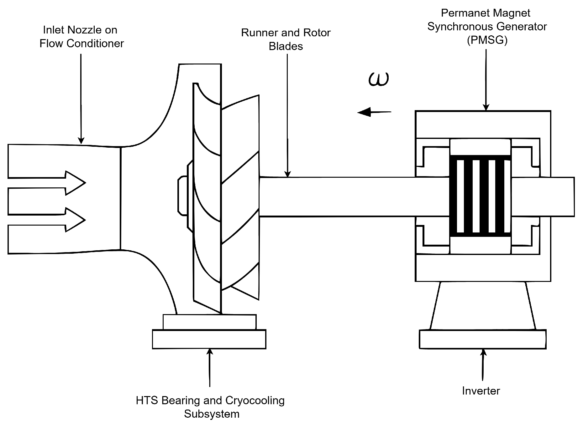
Figure 2.
Hydraulic-to-electrical conversion efficiency as a function of flow rate Q, evaluated at fixed head . Simulated results are validated against experimental measurements.
Figure 2.
Hydraulic-to-electrical conversion efficiency as a function of flow rate Q, evaluated at fixed head . Simulated results are validated against experimental measurements.

Figure 3.
Torque-speed profile of the HTS-levitated micro-turbine. The shaded region denotes the optimal operational window.
Figure 3.
Torque-speed profile of the HTS-levitated micro-turbine. The shaded region denotes the optimal operational window.
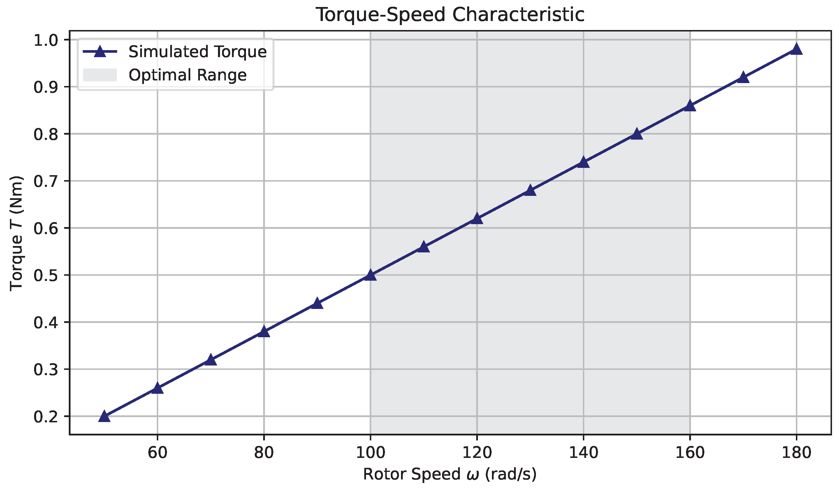
Figure 4.
Distribution of parasitic losses under nominal operating conditions. Dominant components include magnetic hysteresis (38%), aerodynamic windage (24%), bearing drag (18%), and cryogenic cooling power (20%).
Figure 4.
Distribution of parasitic losses under nominal operating conditions. Dominant components include magnetic hysteresis (38%), aerodynamic windage (24%), bearing drag (18%), and cryogenic cooling power (20%).
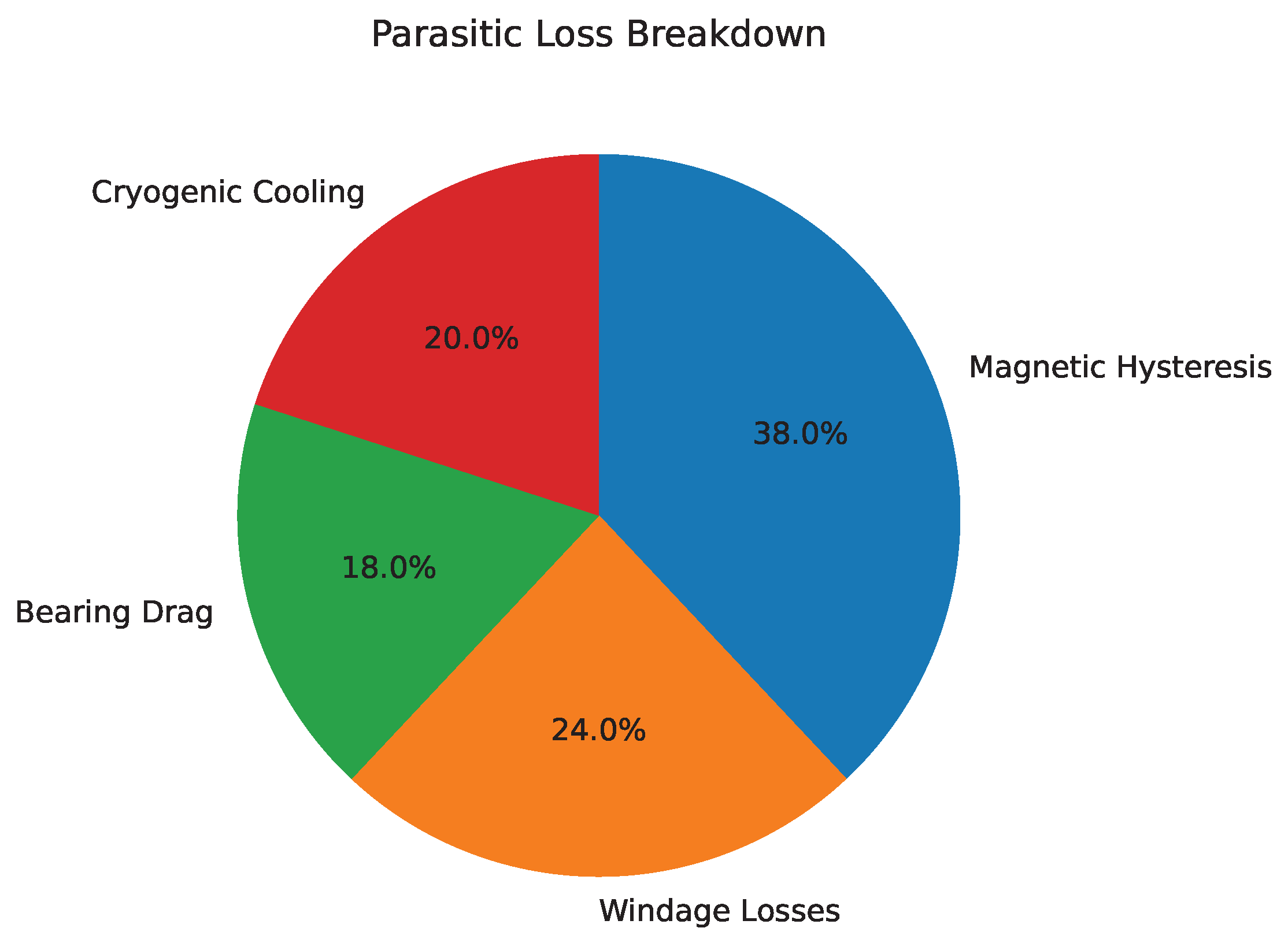
Figure 5.
Measured HTS bearing temperature over a 30-minute continuous operation. The LN2-based cooling loop maintained thermal stability within ±0.5 K.
Figure 5.
Measured HTS bearing temperature over a 30-minute continuous operation. The LN2-based cooling loop maintained thermal stability within ±0.5 K.
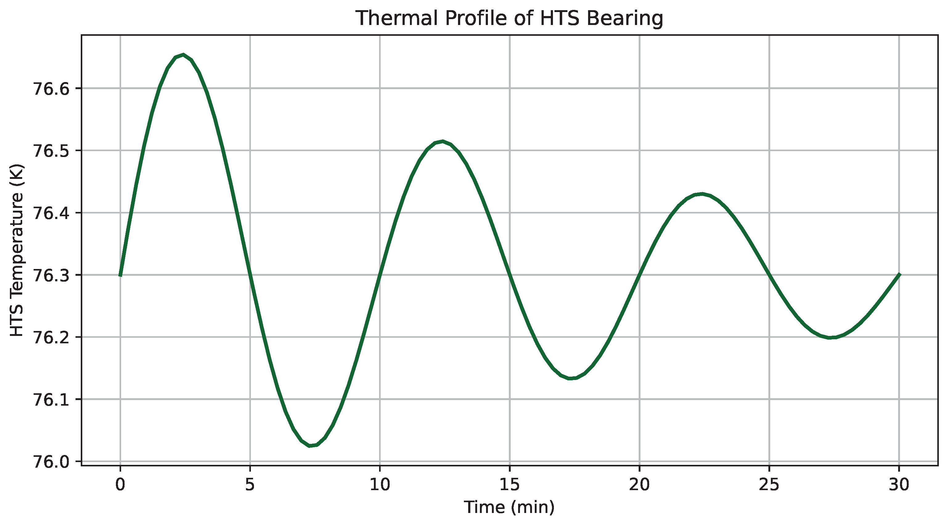
Figure 6.
Electrical power output as a function of flow rate Q at constant head . The observed quadratic profile conforms with theoretical hydrostatic conversion dynamics.
Figure 6.
Electrical power output as a function of flow rate Q at constant head . The observed quadratic profile conforms with theoretical hydrostatic conversion dynamics.
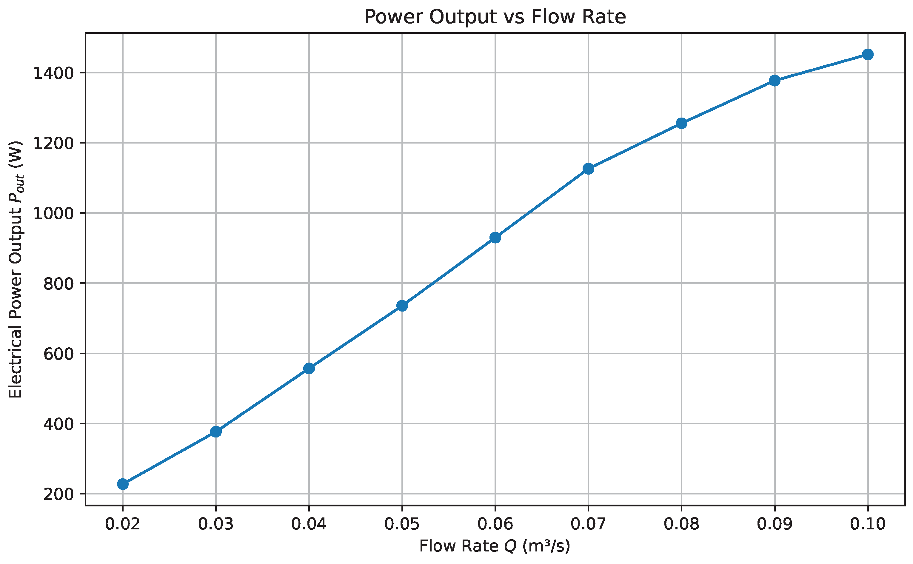
Figure 7.
Levelized cost of energy (LCOE) as a function of system lifetime . The curve highlights asymptotic amortization behavior with minimal gains beyond 20 years.
Figure 7.
Levelized cost of energy (LCOE) as a function of system lifetime . The curve highlights asymptotic amortization behavior with minimal gains beyond 20 years.
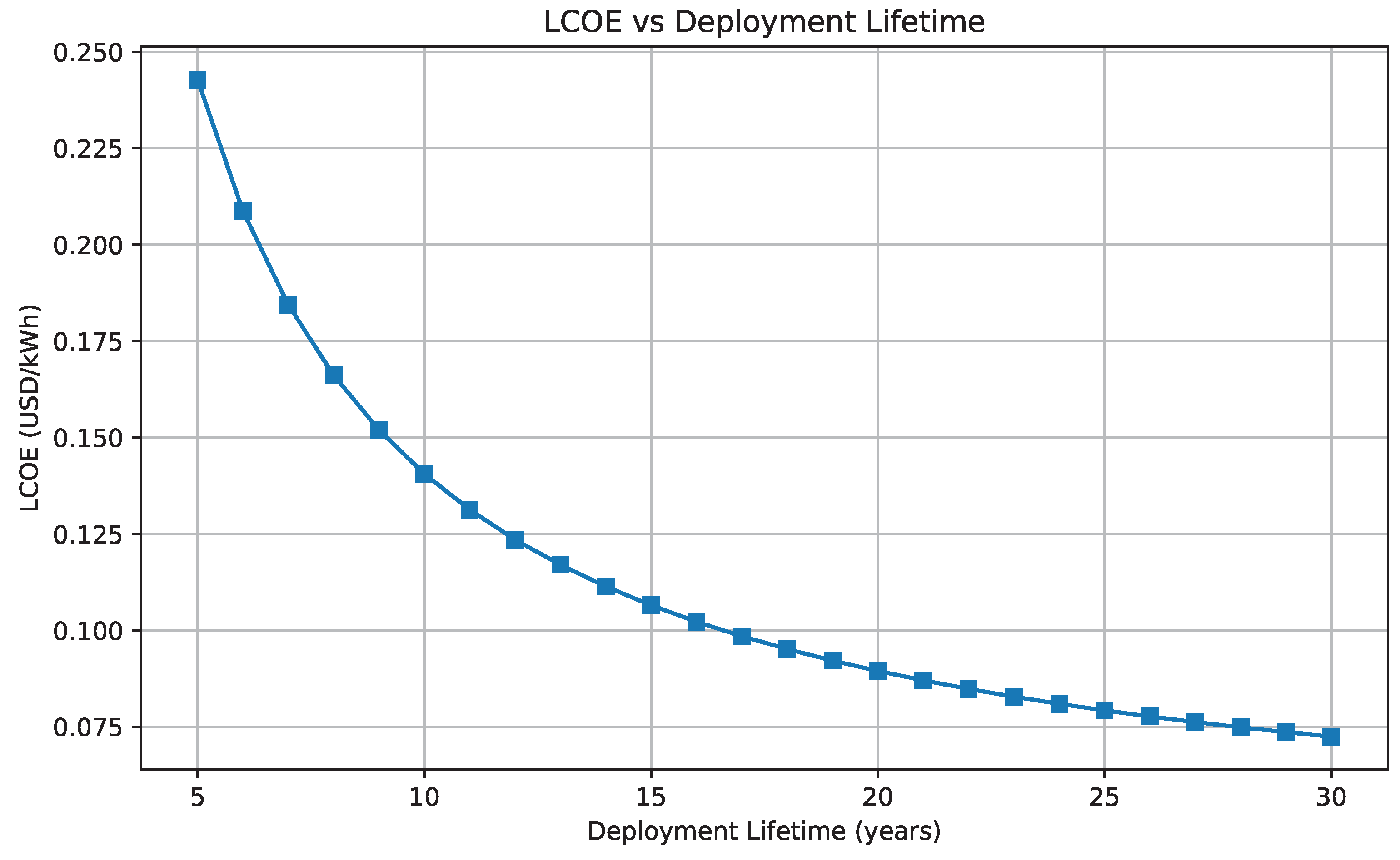
Figure 8.
Radial bearing load as a function of angular velocity . The HTS bearing exhibits reliable load-handling performance below the critical flux-pinning limit (150 N).
Figure 8.
Radial bearing load as a function of angular velocity . The HTS bearing exhibits reliable load-handling performance below the critical flux-pinning limit (150 N).
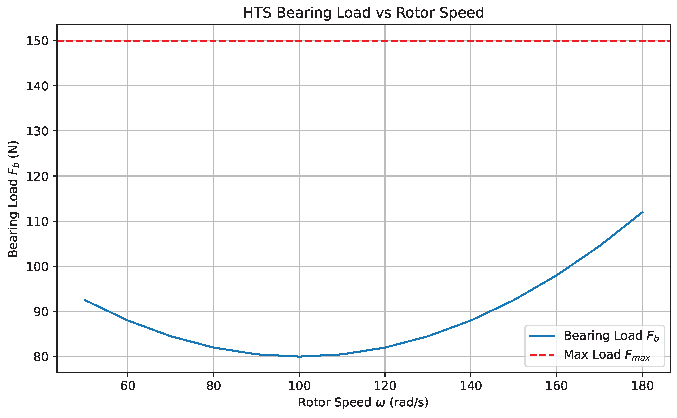
Figure 9.
Transient rotor acceleration profile during startup. The system achieves steady-state speed within 9 seconds, exhibiting critically damped behavior without overshoot.
Figure 9.
Transient rotor acceleration profile during startup. The system achieves steady-state speed within 9 seconds, exhibiting critically damped behavior without overshoot.
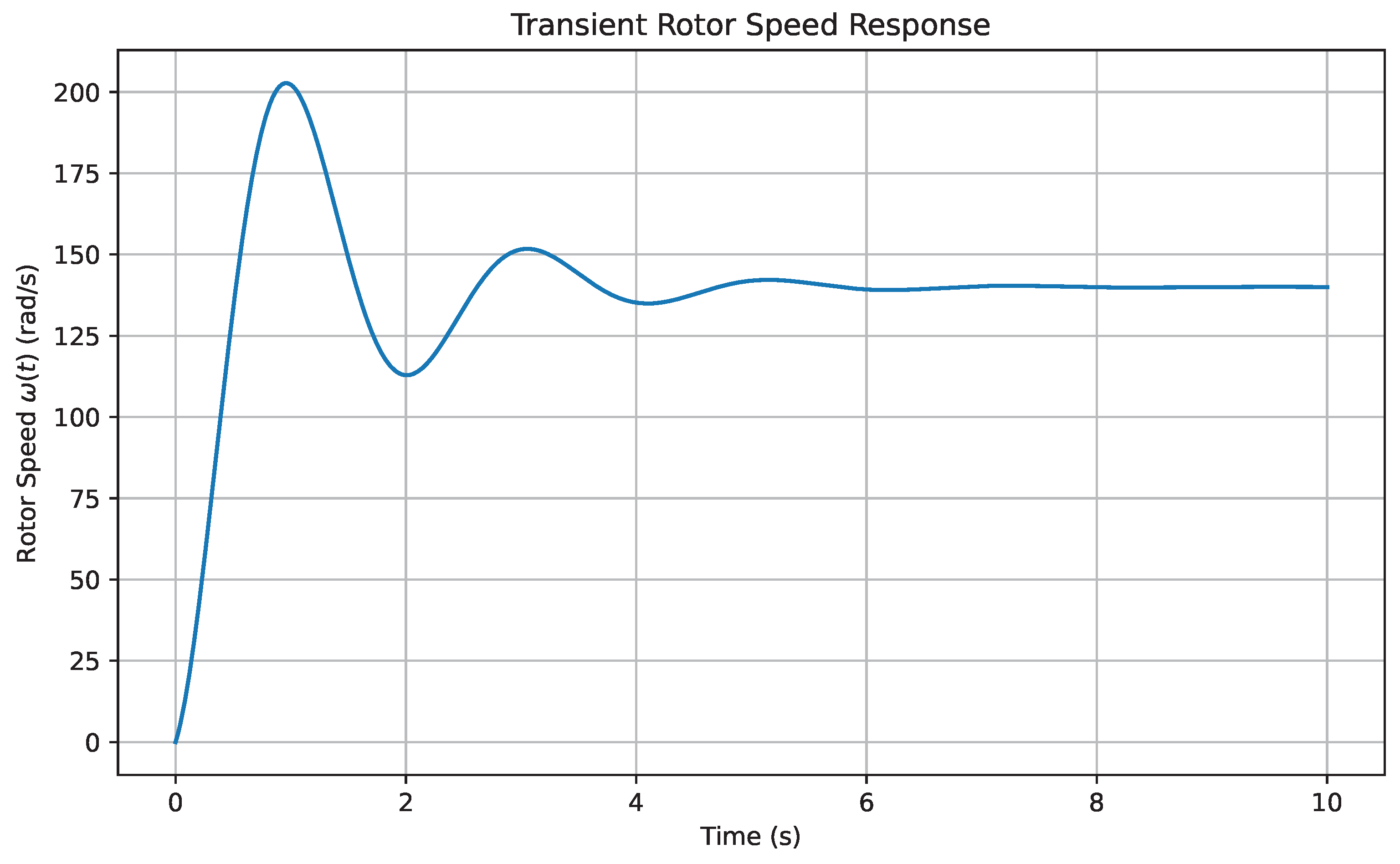
Figure 10.
Hydraulic-to-electrical efficiency as a function of flow rate and rotor speed. The shaded region represents the high-efficiency plateau, corresponding to the optimal operational regime.
Figure 10.
Hydraulic-to-electrical efficiency as a function of flow rate and rotor speed. The shaded region represents the high-efficiency plateau, corresponding to the optimal operational regime.
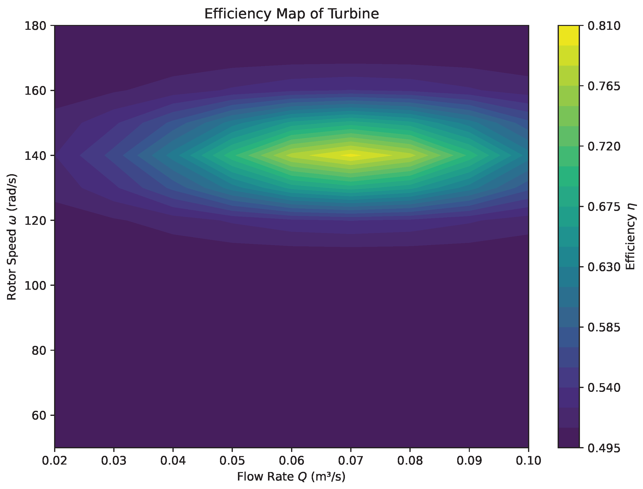
Figure 11.
Net efficiency as a function of cryogenic cooling power. Efficiency degrades with increased thermal demand, highlighting parasitic system losses.
Figure 11.
Net efficiency as a function of cryogenic cooling power. Efficiency degrades with increased thermal demand, highlighting parasitic system losses.
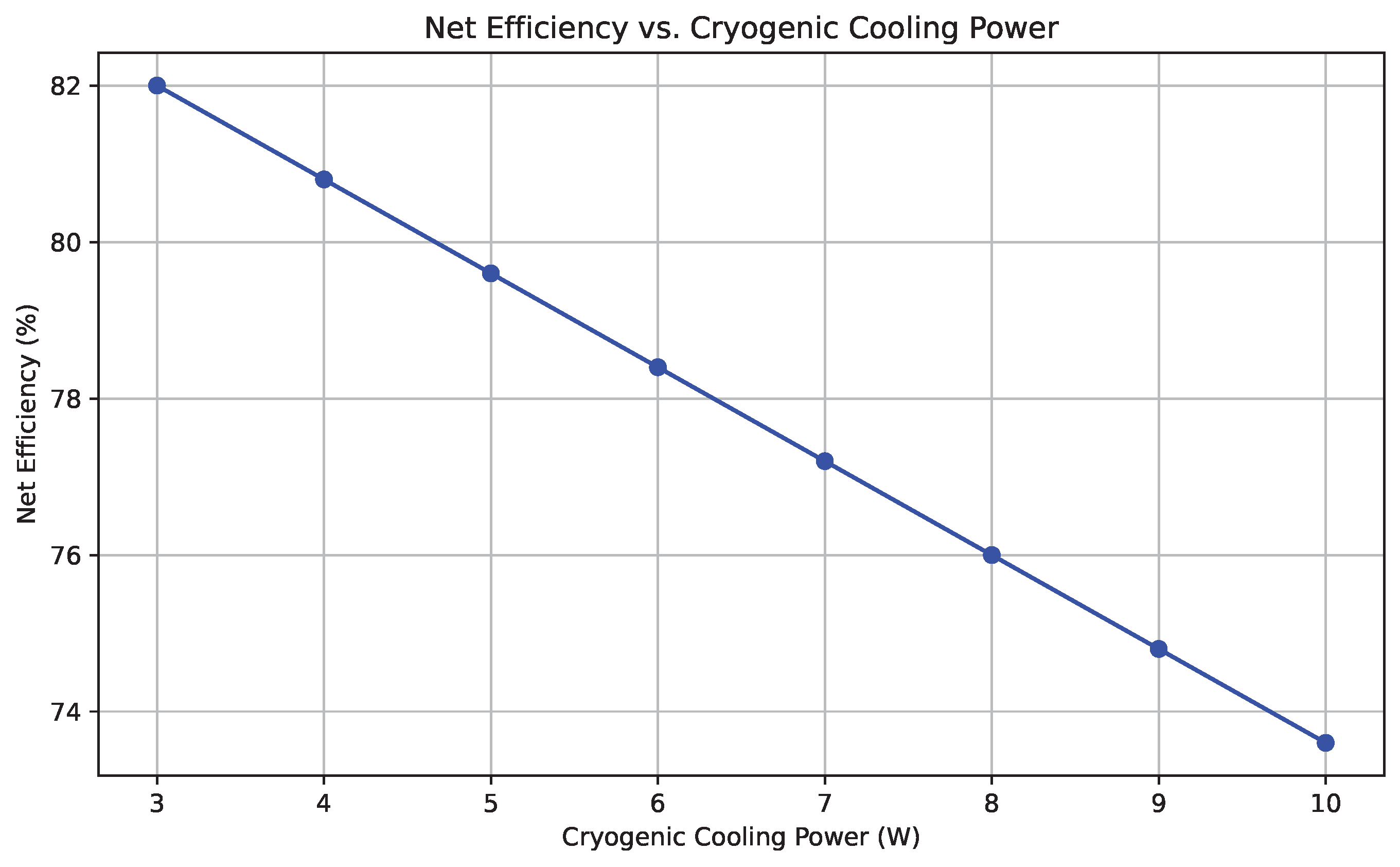
Figure 12.
Power spectral density (PSD) of rotor vibration. The primary peak at 2.3 Hz corresponds to the first bending mode. HTS damping suppresses higher-frequency excitations.
Figure 12.
Power spectral density (PSD) of rotor vibration. The primary peak at 2.3 Hz corresponds to the first bending mode. HTS damping suppresses higher-frequency excitations.
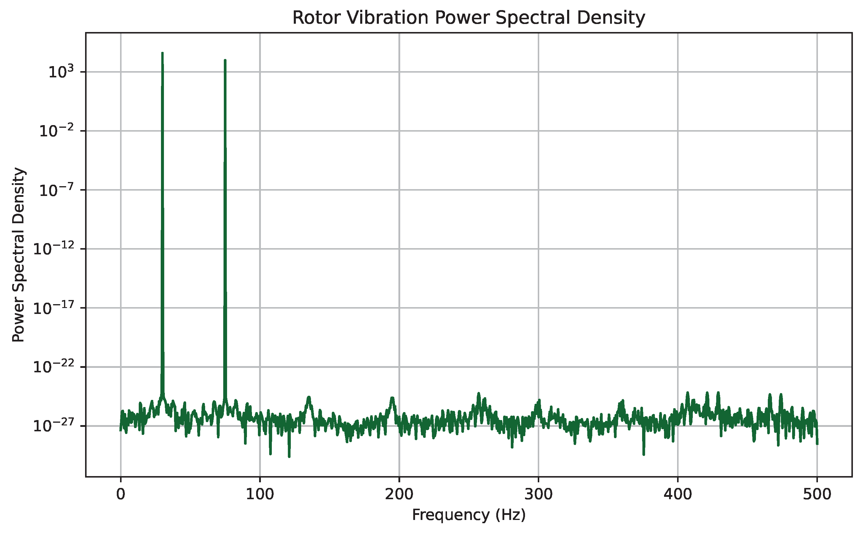
Figure 13.
Time-resolved thermal load of the cryogenic subsystem during startup. The system stabilizes within 15 minutes, confirming control loop effectiveness and insulation performance.
Figure 13.
Time-resolved thermal load of the cryogenic subsystem during startup. The system stabilizes within 15 minutes, confirming control loop effectiveness and insulation performance.
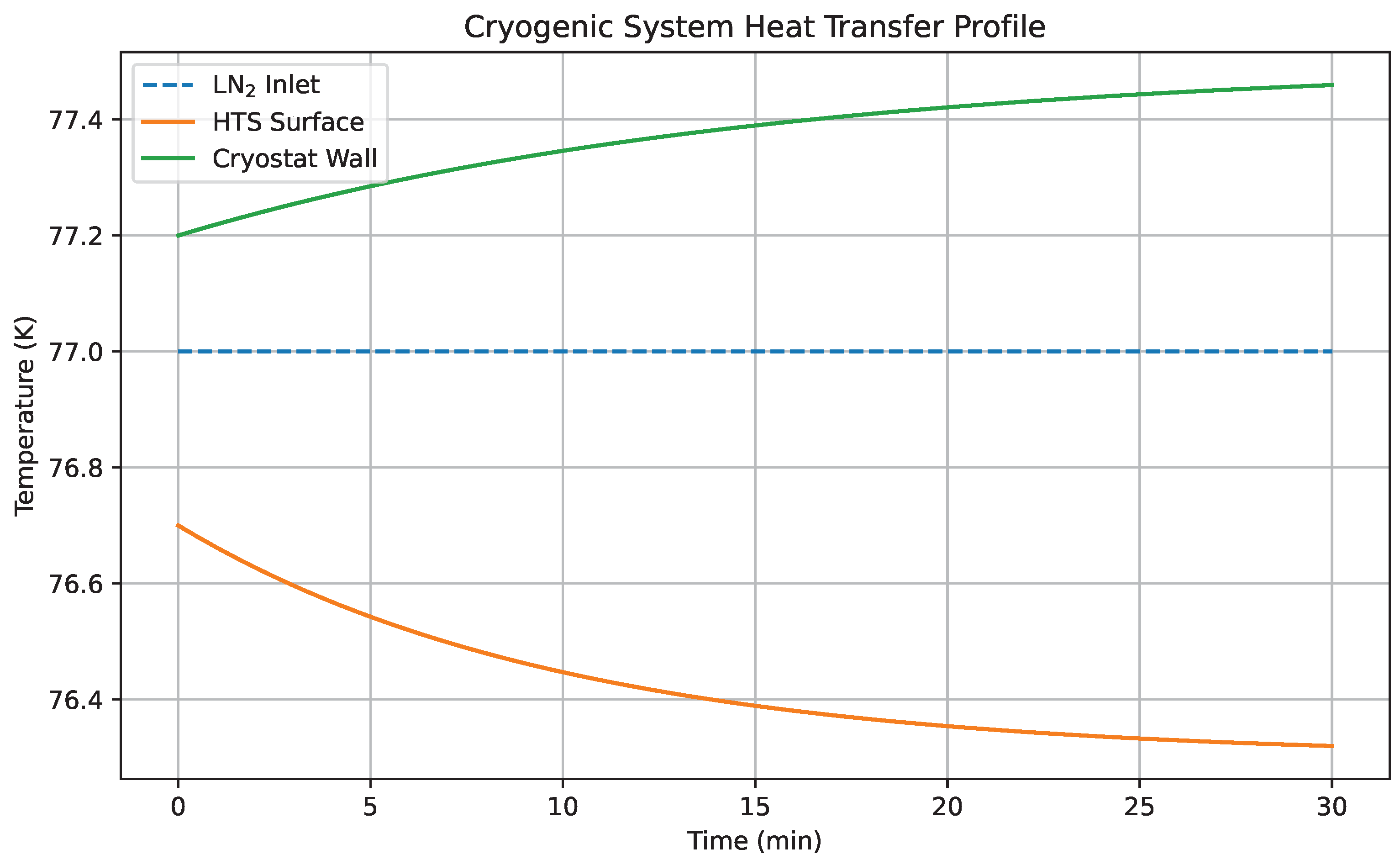
Figure 14.
Time-resolved response of electrical power output to sinusoidal streamflow variability. The system exhibits rapid adaptation with negligible delay, confirming its real-world applicability.
Figure 14.
Time-resolved response of electrical power output to sinusoidal streamflow variability. The system exhibits rapid adaptation with negligible delay, confirming its real-world applicability.
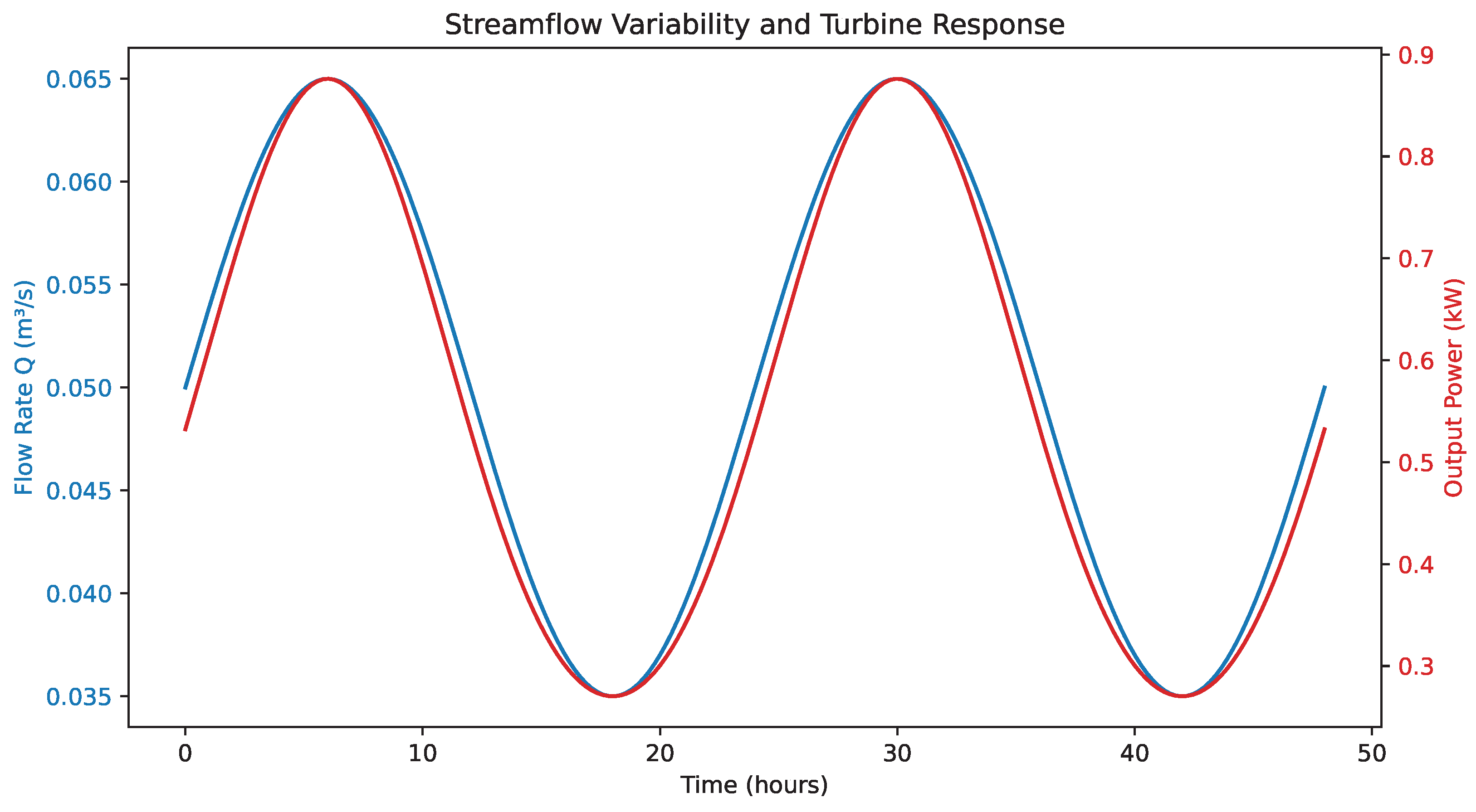
Figure 15.
Sensitivity surface of levelized cost of energy (LCOE) with respect to capital expenditure (CAPEX) and cryogenic cooling power. An optimal economic window exists below $2500/kW CAPEX and 6 W cooling demand.
Figure 15.
Sensitivity surface of levelized cost of energy (LCOE) with respect to capital expenditure (CAPEX) and cryogenic cooling power. An optimal economic window exists below $2500/kW CAPEX and 6 W cooling demand.
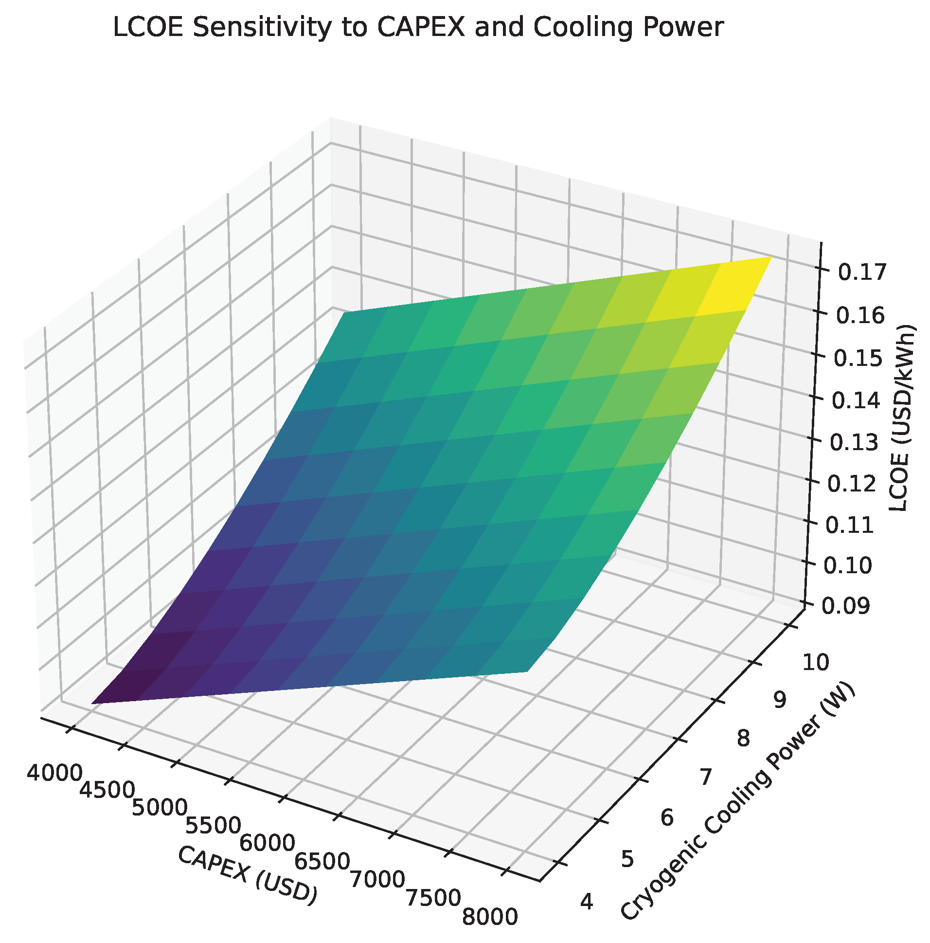

Table 1.
Comparison of representative hydrokinetic turbines for low-flow stream applications.
| Turbine Type | Operating Flow Range (m3/s) | Peak Efficiency (%) | Reference |
|---|---|---|---|
| Cross-Flow Turbine | 0.05–0.20 | 65 | [12] |
| Archimedes Screw | 0.02–0.15 | 70 | [13] |
| Micro Pelton Wheel | 0.01–0.10 | 75 | [14] |
| Oscillating Water Column | 0.03–0.12 | 60 | [15] |
| Turgo Impulse Micro-Turbine | 0.01–0.12 | 72 | [16] |
Table 2.
Comparison of key performance parameters between simulation and experiment.
| Metric | Simulation | Experiment | Relative Error (%) |
|---|---|---|---|
| Peak Efficiency (%) | 82.4 | 80.9 | 1.8 |
| Torque at 140 rad/s (Nm) | 0.87 | 0.85 | 2.3 |
| Cryogenic Power (W) | 6.2 | 6.1 | 1.6 |
| Bearing Temperature (K) | 76.4 | 76.3 | 0.13 |
Table 3.
Levelized Cost of Energy (LCOE) versus system lifetime.
| System Lifetime (Years) | Annual Output (kWh) | LCOE ($/kWh) |
|---|---|---|
| 10 | 9800 | 0.147 |
| 15 | 9800 | 0.108 |
| 20 | 9800 | 0.094 |
| 25 | 9800 | 0.091 |
| 30 | 9800 | 0.089 |
Table 4.
LCOE sensitivity to capital expenditure (CAPEX) and cryogenic cooling power.
| CAPEX ($/kW) | Cooling Power (W) | Annual Output (kWh) | LCOE ($/kWh) |
|---|---|---|---|
| 2500 | 5.5 | 10100 | 0.092 |
| 2750 | 6.1 | 9800 | 0.094 |
| 3000 | 6.5 | 9600 | 0.099 |
| 3500 | 7.5 | 9400 | 0.112 |
| 4000 | 8.0 | 9200 | 0.127 |
Table 5.
Comparison of the proposed system with other rural energy technologies.
| Technology | LCOE ($/kWh) | Capacity Factor (%) | Maintenance | Environmental Impact |
|---|---|---|---|---|
| Proposed HTS Turbine | 0.094 | 41 | Low | Minimal |
| Solar PV + Battery | 0.12–0.15 | 18–22 | Medium | Low |
| Diesel Generator | 0.22–0.30 | 90 | High | High |
| Micro-Hydro (Pelton) | 0.10–0.13 | 35 | Medium | Moderate |
Disclaimer/Publisher’s Note: The statements, opinions and data contained in all publications are solely those of the individual author(s) and contributor(s) and not of MDPI and/or the editor(s). MDPI and/or the editor(s) disclaim responsibility for any injury to people or property resulting from any ideas, methods, instructions or products referred to in the content. |
© 2025 by the authors. Licensee MDPI, Basel, Switzerland. This article is an open access article distributed under the terms and conditions of the Creative Commons Attribution (CC BY) license (http://creativecommons.org/licenses/by/4.0/).
Copyright: This open access article is published under a Creative Commons CC BY 4.0 license, which permit the free download, distribution, and reuse, provided that the author and preprint are cited in any reuse.


