

Submitted:
27 July 2025
Posted:
28 July 2025
You are already at the latest version
Abstract
Based on the single-photon structure model, the standing wave electric 4-photon (SWE4-P) composite, the standing wave magnetic 4-photon (SWM4-P) composite in one-dimensional longitudinal constraint space and the standing wave 8-photon (SW8-P) composite structure in the laser microcavity are derived; The electromagnetic field of the TM010 mode in microwave cylindrical resonant cavity is studied and analyzed, and the photon structure basic unit of this mode has been identified as the standing wave cylindrical 8-photon composite structure. The cylindrical photon is of the same size as the cavity volume, the photon volume being V=. The standing wave 8-photons composite structure contains a SWE4-P composite and a SWM4-P composite with a phase difference of 90°. So, the energy unit of the TM010 mode in the cavity is 8hf.
Keywords:
standing wave electric 4-photon (SWE4-P) composite
; standing wave magnetic 4-photon (SWM4-P) composite
; standing wave 8-photon (SW8-P) composite structure
1. Introduction
After the canonical quantization of the electromagnetic (EM) field [1,2,3], the concepts of two transverse photons, i.e., right-spin photon and left-spin photon, were obtained. “Photons, massless spin 1 particles, have only two eigenvalues of their spin along the direction of their propagation (wave vector k), ±ℏ. These two spin values correspond to right- and left-handed circular polarizations, respectively [4]. However, this single-photon does not correspond to the concept of circularly polarized EM field in classical electrodynamics [5]. Jackson wrote in his book: “The circularly polarized states are composite, which is an easy way of allowing for a phase difference between the two linearly polarized (LP) states out of which the circular states are constructed”.
A single-photon state is generally considered to contain only one photon, and it has multiple polarization quantum states [6,7,8,9,10,11,12,13,14,15,16], such as horizontal linear polarization (HLP), vertical linear polarization (VLP), diagonal (45°) linear polarization (DLP), antidiagonal (-45°) linear polarization (ALP), right-handed circular polarization (RCP), left-handed circular polarization (LCP), etc. In fact, these polarization states are not true single-photon states. The results of the single-photon structure model [17] show that these quantum states are all 4-photon composite monomer. Here to distinguish the circular polarization states,the photons with spin angular momentum of ±ℏ are defined as right/left-spin photons; while the 4-photon composite monomer with spin angular momentum of ±4ℏ are called right/left-handed circular polarization 4-photon monomers.
Photon is deemed by some people a derived concept: it arises as a ripple of the EM field. Or instead, they view the EM field as fundamental, with the photon appearing only when we correctly treat the field in a manner consistent with quantum theory. The others view the photon quantum as fundamental with the EM field arising only in some classical limit from a collection of quantum photons. This study considers that photons and EM fields are objectively existing, and should not be changed by mathematical processing. It is very necessary to reveal their internal unity and consistency.
Particle physics says that “the excited state of the EM field is manifested by the appearance of photons”. “The excited state of the electron field is manifested by the appearance of electrons”. By analogy, a particle is the manifestation of its field in an excited state. The atomic excited state is defined as the shell electrons are in a high energy level and a photon equal to the energy level difference must be radiated when the electrons transition to a lower energy level. However, the “EM field excited state” is not defined, and the results of this study will clarify this fuzzy concept.
The single photon structure model [17] is to construct the photon quantum with the EM field vector matter. Conversely, can the classical continuous EM field in constraint spaces be constructed from photons? The answer is yes. For example, the alternating electric fields in parallel-plate capacitors, the pure alternating magnetic fields in current-carrying solenoid coils, the EM fields of single longitudinal mode TEM00 in a laser [18,19] microcavity, the EM fields of the fundamental mode TM010 in microwave cylindrical resonant (MCR) cavity can all be constructed with multi-photon composite structure.
The constraint spaces can be divided into two categories, longitudinal constraints and transverse constraints, the former will form standing waves, the latter will still be traveling waves. Cavity types are standing wave systems, and waveguide types are traveling wave systems. MCR cavities are three-dimensional constraint spaces; guide-wave systems are laterally two-dimensional constraint spaces. This paper is devoted to a discussion of the photon structure of standing-wave EM fields, and does not enter into a discussion of the travelling-wave EM fields of guide-wave systems, in the interests of brevity.
2. LP Standing Wave 4-Photon Composite
When a pair of LP photons is reflected back and forth between two parallel conducting planes, the reflected photon pair at the incident point has a half-wave loss relative to the incident photon pair. There are two cases: one is that the magnetic field component is reversed, and the electric field component remains unchanged. The other is that the electric field component is reversed, and the magnetic field component remains unchanged. Thus, between two parallel conducting planes, when the reflected LP photon pairs meet and superimpose with the incident LP photon pairs, to form a standing wave (since their velocity cancel out to zero) 4-photon (SW4-P) composite, there are two types: One is the magnetic field component canceling out to zero, leaving only the electric field component to overlap and form a LP standing wave electric 4-photon (SWE4-P) composite. The second is that the electric field components cancel each other out to zero, leaving only the magnetic field components to overlap and form a standing wave magnetic 4-photon (SWM4-P) composite. The following will be discussed separately.
2.1. SWE4-P Composite Structure
Between two parallel conducting planes, suppose E1H1 and E2H2 are the incident LP photon pairs; E3H3 and E4H4 are the reflected LP photon pairs, both is said with respect to one of the reflecting planes. When they meet and co-volume superpose, the electric field components of the photon pairs E1H1 and E2H2 polarized in the y axis are in phase with the electric field components of the photon pairs E3H3 and E4H4, while their magnetic field components are 180° of phase, as shown in Figure 1(a), they form a SWE4-P composite. Figure 1(a), (b), (c), and (d) show the orientation of the electric-field and magnetic-field substance vectors in each of the four photons at phase points and , respectively. To simplify the diagram, the orientation of the wave vector k and angular momentum j of each photon is not shown.
Where the photon E1H1 and the photon E3H3 are the right-spin photon along the k direction and left-spin photon along the -k direction, respectively, and their resultant wave vector is zero and the resultant velocity is also zero, becoming a standing wave photon pair; their magnetic field components H1 and H3 are always in opposite directions and become hidden components that are invisible, and their electric field components E1 and E3 are always in phase and doubled, becoming “manifest components”.
Likewise, the photons E2H2 and E4H4 are the left-spin photon along the k direction and the right-spin photon along the -k direction, respectively, and their resultant wave vector is equal to zero, and the resultant velocity is also equal to zero, they also become a standing wave photon pair; the synthetic magnetic field component is also a “hidden component”, and the electric field component is also a “manifest component”.
The total spin angular momentum of the homo-body four photons synthesis is equal to zero, the total wave vector is also equal to zero, the total magnetic field component is always equal to zero, and there is only the total electric field component Ey, which is shown a pure electric field oscillating harmonically along the y-axis.
Its energy
The SWE4-P composite structure provide a pure alternating electric field, similar to the pure alternating field inside a capacitor. It can be said that the SWE4-P composite is the basic unit that constitutes a pure alternating electric field.
2.2. SWM4-P Composite Structure
Between the two parallel conducting planes, the photons H1E1 and H2E2 are the reflected x-linearly polarized photon pairs (wave vector -k), and the photons H3E3 and H4E4 are the incident x-linearly polarized photon pairs (wave vector k). They meet and superpose into a 4-photon composite. Among them, H1E1 is left-spin photon along the -k direction, H3E3 is right-spin photon along k direction, they form one stationary pair; H2E2 is right-spin photon along the -k direction, H4E4 is left-spin photon along the k direction, they form the other stationary pair. At 90° phase, the phase of the magnetic field components of the photon pairs H1E1 and H2E2 is the same as that of the photon pair H3E3 and H4E4, their magnetic field pointing to the -x axis as shown in Figure 2(b), while the phase of their electric field components is always opposite and cancel each other out to zero. Figure 2(a), (b), (c), and (d) show the orientation of the magnetic- and electric- field substance vectors of each photon at phase and , respectively, with the wave vector and angular momentum orientations of each photon not shown.
The synthetic total spin angular momentum of the four photons of the composite is equal to zero, the total wave vector is also equal to zero, the total electric field component is always equal to zero, and there is only one total magnetic field component Hx, without other components, which is shown as a pure magnetic field oscillate harmonically along the x-axis,
The total magnetic field is a pure alternating magnetic field, just like the pure alternating magnetic field inside the current-carrying solenoid coil. It is seen that the SWM4-P composite is the basic unit that constitutes the alternating magnetic field.
Just like the SWE4-P composite, there is no net energy flow, Poynting vector s = 0. As for the effective energy of the SWM4-P composite, there is
This shows that the energy of the SWM4-P composite is also the energy () of 4 single photons, and the conservation of energy is observed.
3. The Photon Structure of the Single Longitudinal Mode TEM00 in a Laser Microcavity
The simplest laser microcavity consists of an active medium and two reflecting mirrors and is an open cavity without boundaries on the sides. The eigenmode photon runs back and forth between the two reflective surfaces, activating the medium particles to produce stimulated emission, and the positive feedback continuously proliferates produce optical amplification. The function of the resonator cavity is to preferentially amplify the eigenmode of light with a certain frequency and consistent direction, while suppressing light of other frequency and directions. A strong beam of light is formed in the cavity with the same direction of propagation, frequency and phase, i.e., laser. To extract the laser from the cavity, one of the reflecting mirrors can be made partially transmissive [18,19], with the transmitted part becoming the available laser, and the reflected part in the cavity to continue to proliferate photons. The single longitudinal mode TEM00 in the optical resonator cavity is a standing wave mode, and the basic unit of the output laser is a propagating LP4-photon (LP4-P) monomer [17]. Intra cavity photon structure is a standing wave 8-photon (SW8-P) composite structure formed by superposition of the reflected LP4-P monomer and the incident LP4-P monomer, as shown in Figure 3. The LP4-P monomer (E1,H1, E1′,H1′,E2,H2,E2′H2′) can either be transmitted out as an output laser unit or reflected back.
When the laser output mirror is taken as the reflection reference plane, and the tangential component of the electric field on the reflection surface is demanded to be equal to zero, requiring that electric field component of the reflected photon is reversed (half-wave loss), while the magnetic field component remains unchanged. So, the reflected monomer (E3,H3,E3′,H3′,E4,H4,E4′H4′) and the incident monomer (E1,H1,E1′,H1′,E2,H2,E2′H2′) meet and superpose into an 8-photon composite structure along the way. Since the wave vectors cancel out in opposite directions, the velocities also cancel out to zero, resulting in a standing wave 8-photon (SW8-P) composite structure. This composite structure is just a specific structure in the constraint space, not a stable structure.
Figure 4a shows that the electric field E1’ of photon 1’ and electric E3 of photon 3 are always opposite and cancel each other out to zero, and the electric field E1 of photon 1 and electric field E3’ of photon 3’ are also always opposite and cancel each other out to zero. Only E2, E2’, E4, E4’ contribute to the x-directed electric field, obviously
The four photons E2H2,E2’H2’,E4H4,E4’H4’ forms a standing wave electric 4-photon (SWE4-P) composite, which produces a pure alternating electric field.
Figure 4b shows that the magnetic field components H2 of photon 2 and H4’ of photon 4’ are always in opposite directions, canceling each other out to zero; The magnetic field components H2’ of photon 2’ and H4 of photon 4 are always opposite, canceling each other out to zero. Only H1, H1’, H3, H3’ contribute to the magnetic field in the y direction,
The four photons H1E1,H1’E1’,H3E3,H3’E3’ forms a standing wave magnetic 4-photon (SWM4-P) composite, which produces a pure alternating magnetic field.
It is apparent that in this standing wave 8-photon composite structure, four of the photons have their magnetic fields canceled to zero because of their opposite directions; the electric fields of these four photons are doubled and strengthened because of their same directions, thus only the electric field is shown. In this standing wave 8-photon structure, the other four photons are just canceled their electric fields and only display the magnetic field. Moreover, the electric field and magnetic field are orthogonal, and their time phases differ by 90°, i.e., sine and cosine functions. This is determined by the fact that the electromagnetic field matter in the single photon structure model is an orthogonal vector, which is a universal law. The total energy of the SW8-P composite structure,
4. The Photon Structure of the TM010 Mode in a MCR Cavity
The TM010 mode of the MCR cavity has the lowest resonant frequency () and the longest resonant wavelength (). TM010 single-mode operation is often used to accelerate charged particles, and the cavity is called an accelerating cavity [20], and the mode is called an accelerating mode. Now we begin to discuss the microwave photon structures of the TM010 mode in the MCR cavity, and compare it with the mathematical description of the classical EM field.
4.1. The EM Field of the TM010 Mode in a MCR Cavity
In the MCR cavity with inner radius R and length L, the exact expressions of the EM field distribution of all resonant modes in the cavity are given in classical electrodynamics [21,22]. The EM field distribution of the TM010 mode is the simplest, as follows:
The TM010 mode is an accelerating mode with only two field components. The electric field component Ez is in the z-axis direction, while the magnetic field component is in the angular direction, and the phase difference between the electric field component and the magnetic field component is . Where J0(x) is the zero-order Bessel function, J0′(x) is the derivative of zero-order Bessel function, and , is the first-order Bessel function. The j01 is the first zero point of the zero-order Bessel function, and its value j01=2.405. The Bessel function curves are shown in Figure 5a. On the =0 axis of the cavity, J0(0) =1, it means that the electric field has the maximum value, Ez (0, z) =E0. At the =R, the side wall of the cavity, because J0(2.405) =0, the electric field is zero, i.e., Ez (R, z) = 0. The magnetic field at the =0 axis, because , it means that the magnetic field is zero, i.e., Hφ(0, z)=0. However, near the side wall of the cavity, where ρ= R, J1(2.405)= 0.5019, the magnetic field Hφ(R, z) has a bigger value, using the relation , the Hφ in Eq. (8) can be as
The amplitude of the angular magnetic field at = R is proportional to J1(2.405) (Figure 5a). The spatial distribution of the classical electric and magnetic fields in most spaces between the cavity axis and the cavity side wall is shown in Figure 5b (note there is 90° phase difference between the electric field and the magnetic field). The field in the cavity is axisymmetric, there is no periodicity in both the eφ-direction and the ez-direction. The electron beam bunch is injected along the z-axis in a suitable half-period, which can be accelerated by the axial electric field Ez. When the electric field peaks to accelerate the charged particles, the transverse circular magnetic field is nearly zero, since there is a 90° phase difference between the electric field Ez and the magnetic field Hφ.
4.2. Consideration to Construct the EM Field of the TM010 Mode with Photons
The intracavity field is a standing wave field. A single photon cannot be localized, a single LP photon pair cannot be localized either. Only co-volume identical LP photon pairs with opposite wave vectors k can be stationary since the wave vectors cancel out to zero, thereby the velocities also cancel out to zero (by the way, the photons in a MCR cavity are zero velocity photons). That is to say, the photon structure allowed in the resonant cavity can only be the standing wave 4-photon composite structure. Although, they have no translational velocity, but they do keep a spin velocity, i.e., a spin angular velocity.
Then we look at the resonant wavelength of TM010 mode, , and the photon diameter in free space, d=0.5032λ, now let < 2R. Compared with the cavity diameter 2R and cavity length L<2R, the photon size is not small and comparable to the cavity size, so the cavity volume can only accommodate one photon volume.
Furthermore, the photons in the cavity must be deformed into a cylinder to satisfy the Helmholtz equation and boundary conditions of the MCR cavity. The cylindrical photons of length L and radius R have the cavity axis as their symmetry axis. The electric-field substance vector, the magnetic-field substance vector, the wave vector and the spin angular momentum vector of the photon in free space are all Cartesian vectors [17]. After entering the constraint cavity space, due to the interaction with the cavity wall, these vectors of each cylindrical photon turn into the orthogonal curve vectors (Eez, Heφ, keρ) of the cylindrical coordinate system (ρ, φ, z), eρ, eφ, ez are unit vectors on the ρ-, φ-, z-axis, respectively.
On the ρ=0 axis, J0(0) =1, J1(0)=0, so Ez(0,z)=E0cosωt, and Hφ(0,z)=0. Without magnetic field, it is a pure alternating electric field; And at the side wall of the cavity where r=R, J0(2.405) =0, J1(2.405) ≈0.519, so Ez (R, φ, z) = 0, Hφ (R, φ, z) = -ωε0(R/2.405)J1(2.405)E0sinωt. Without electric field, it is a pure alternating magnetic field. The electric-field and magnetic-filed components are mutually phase-shifted by 90° and superimposed orthogonally elsewhere.
For the amplitude of the electric field Ez given by Eq. (8), the amplitude of the magnetic field Hφ given by Eq. (9), it is observed in Figure 5(a) that at x≈1.44, the zero-order Bessel function J0(x) and the first-order Bessel function J1(x) have a point of intersection, i.e., J0(1.44) ≈J1(1.44). Using this value, for any microwave frequency it can be calculated the amplitude ratio Ez/Hφ= 1/(ωε0R/2.405) ≈377Ω, which is consistent with the wave impedance of the photon [17].
Considering that the field in the cavity is axisymmetric, there is no periodicity in both the angular eφ direction and the longitudinal ez-direction. For cylindrical photons, the electric and magnetic field matter vectors are located in the cylindrical surface (z, φ); the wave vector and angular momentum along to the radial eρor -eρ.
In order to satisfy the conditions of pure electric field Ez (near axis) and pure magnetic field (near side wall), and to satisfy the conditions of phase difference of 90° between them, need two kinds of SW4-photon composite. The SWE4-P composite can provide a pure electric field along z-direction. The field substance distribution of its each photon along eρ- direction obeys function, is uniform along both the eφ- and ez-directions. The SWM4-P composite can provide a pure magnetic field Hφ along the eφ-direction. The field substance distribution of its each photon along eρ- direction obeys function, is uniform along both the eφ- and ez-directions.
The superposition of two kinds of SW4-P composite provides both the harmonic oscillation electric field along to the z-direction and the harmonic oscillation magnetic field along to the eφ-direction in the MCR cavity. The SWE4-P composite and the SWM4-P composite are configured in a 1:1 ratio, satisfying the principle of equal partition of EM energy in the cavity.
About the changes over time, demand that the SWE4-P composite obey cosωt function and the SWM4-P composite obey the sinωt function. Looking at the structure of the EM field given by Eq. (8) and (9) and comparing it with the electric and magnetic field expressions for the SW8-P composite structure given in Section 3, one easily realizes that this TM010 mode’s photon structure is a typical SW8-P composite structure. There is an inherent correlation between the SWE4-P composite and the SWM4-P composite, that is, the spatial orthogonal, the time phase difference of 90° relation, and the volume integral of its electric field energy is equal to that of the magnetic field energy (i.e., each half of the EM energy).
This SW8-P composite structure is the basic unit of the TM010 mode photon structure. Below we will discuss each of these in detail.
4.2.1. The SWE4-P Composite of the TM010 Mode
The EM field matter distribution of each photon in the cylindrical-shaped SWE4-P composite follows the zero-order Bessel function along the radial ρ and is uniformly distributed along both the angular φ and the axis z. For a cylindrical photon, the electric and magnetic field matter vectors (E, H) of each photon are located in the cylindrical surface (φ, z), while the wave vector k and angular momentum j are in the radial (eρ) direction. Right/left-spin photons in free space obey the spin rule, how to implement the spin rule for right/left-spin cylindrical photons? We divide each cylindrical photon into an infinite number of differential volumes (dV) by using the three orthogonal curve-surfaces ((r, φ), (φ, z), (z, r)). In each dV the EM field matter vectors (E, H) of each photon spin-rotate about the local wave vector k at ω according to the spin rules like as in the Cartesian coordinate system as shown in Figure 6.
Intracavity four cylindrical photons E1H1, E2H2, E3H3 and E4H4, at ωt=0°, are shown in Figure 6 (a), (b), (c) and (d), respectively. The electric field substance vectors are all along the z-axis, which becomes the manifest component; while the magnetic field substance vectors cancel out to zero, which become a hidden component. The direction of the electric field is along the z axis, and the magnetic field direction is along the angular φ and connected the head and the tail. In order to see this clearly, take the same dV as shown in (a’), (b’), (c’) and (d’) of Figure 6. The H1 of photon E1H1 is along the -eφ direction, E1H1 right-spin, both its wave vector k and its angular momentum j are along the eρ direction; The H2 of photon E2H2 is also along the -eφ direction, E2H2 left-spin, its wave vector k is along the eρ direction, but its angular momentum j is along the -eρ direction; The H3 of photon E3H3 is along the eφ direction, E3H3 left-spin, its wave vector k along the -eρ direction, but its angular momentum j along the eρ direction; The H4 of photon E4H4 is along the eφ direction, E4H4 right-spin, both its wave vector k and angular momentum j are along the -eρ direction. In a word, the field substances superposition of the same dV belonging to these four photons results in zero magnetic-field vector synthesis, zero total wave vector synthesis, zero total angular momentum synthesis and four times electric-field vector synthesis of single photon. This result is correct for the entire SWE4-P composite.
Figure 6 shows only the vector direction at the initial phase (ωt=0°) of photon E1H1, E2H2, E3H3 and E4H4 within the SWE4-P composite. Figure 7(a), (b), (c) and (d) show the direction of the electric field substance vector and the magnetic field substance vector in the same differential volume belonging to four different photons at 0°, 90°, 180° and 270° phase points, respectively. Note that H1 and H3 are always in opposite directions and cancel each other out to zero, and H2 and H4 are always in opposite and cancel each other out to zero. The dV, (a’), (b’), (c’), (d’) of each photon in Figure 6 only corresponds to Figure 7(a).
The result of superposition of four photons is that the total magnetic field is always 0, invisible, and the total electric field E is a manifest component which is four times the intensity of the single photon. There is no net wave vector and no net angular momentum in any dV, but the substances in each dV which belongs to each photon keep independent spin. The z-direction electric field of TM010 mode is contributed by the SWE4-P composite alone. Obviously, it is the basic unit of the z-direction electric field of TM010 mode in the cavity. As a result, the pure electric field oscillates along the z-direction with angular frequency ω. The electric field generated by the SWE4-P composite can be expressed as bellow:
4.2.2. The SWM4-P Composite of the TM010 Mode
Each photon in the SWM4-P composite is also deformed into a cylinder of length L and radius R. The EM field matter distribution of each photon in the SWM4-P composite follows the first-order Bessel function along the radial ρ and is uniformly distributed along the angular φ and the axis z. The electric field E and magnetic field H of each photon are located in the cylindrical surface (φ, z), the wave vector k and angular momentum j are along the eρ direction, as shown in Figure 8. A significant difference from the SWE4-P composite is that the superposition of four photons results in that the total electric field component is zero. And the total magnetic field component along the eφ direction, and oscillates harmonically at the angular frequency ω.
Take a dV to illustrate the physical mechanism. As shown in Figure 8, at ωt = 90° phase, the magnetic field Hi (i=1,2,3,4) belonging to the four photons of the SWM4-P composite are all along the -eφ direction, while their electric field components are pairwise opposite to each other and cancel out to zero. Specifically, in the dV, the magnetic fieldH1 belonging to photon 1 is along the -eφ direction, the photon H1E1 left-spin, its wave vector k1 is along the -eρ direction, and its angular momentum j1 is along the eρ direction as shown in Figure 8(a’); the magnetic field H2 belonging to photon 2 is also along the -eφ direction, the photon H2E2 right-spin, both its wave vector k2 and angular momentum j2 are along the -eρ direction as shown in Figure 8(b’); the magnetic field H3 belonging to photon 3 is along the -eφ direction, the photon H3E3 right-spin, both its wave vector k3 and angular momentum j3 are along the eρ direction as shown in Figure 8(c’); the magnetic field H4 belonging to photon 4 is along the -eφ direction, the photon H4E4 left-spin, its wave vector k4 is along the eρ direction, its angular momentum j4 is along the -eρ direction as shown in Figure 8(d’). In a word, in the same dV belonging to the four photons, the superposition result is that the total electric field vector synthesis is zero, the total wave vector synthesis is zero, the total angular momentum synthesis is zero, and the total magnetic field vector synthesis is four times that of the single photon. This result is correct for the whole SWM4-P composite.
Figure 9 (a), (b), (c) and (d) show the direction of the electric field substance vector and the magnetic field substance vector in the dV shared by four cylindrical photons at the four phase points of 0°,90°,180° and 270°, respectively. Note the E1 and E3 always cancel each other out to zero, the E2 and E4 always also cancel each other out to zero. The field synthesized by the four cylinder-photons is a pure magnetic field. The magnetic field produced by the SWM4-P composite harmonically oscillates at angular frequency ω along the eφ direction,
The SWM4-P composite is the basic unit of the angular magnetic field of TM010 mode in the MCR cavity.
4.3. The SW8-P Composite Structure of the TM010 Mode
A superposition of a SWE4-P composite and a SWM4-P composite with a total of 8 photons as a basic unit constitutes the EM field of the TM010 mode. The pure electric field Ez near the axis is contributed by the SWE4-P composite alone, the pure magnetic field Hφ near the side wall is by the SWM4-P composite alone, and the mixed electric and magnetic fields with a phase difference of 90° in other regions are jointly contributed by both SWE4-P composite and SWM4-P composite. The co-volume superposition of the SWE4-P and SWM4-P composites (total of 8 photons) as the basic unit provides the energy storage for the TM010 of the MCR cavity. That is to say, the energy storage in the cavity increases step by step with the unit () of 8 photons. This is a result deduced from single photon structure model [17].
The physical process that occurs in the cavity can be understood from the classical EM theory. As the electric and magnetic fields of eigenmode that satisfy the Helmholtz equation and boundary conditions of the MCR cavity, oscillating at angular frequency ω. The electric energy is converted into the magnetic energy, and the magnetic energy is converted into the electric energy, and so on, the electric and magnetic energies are converted into each other.
From the photon′s point of view, the physical process occurring in the cavity is the result of the EM field vector matter spin-rotate independently about their respective wave vectors () at the angular velocity ω in each dV of the eight cylindrical photons. This physical mechanism is more intuitive, concise and clear than the abstract image of “electric and magnetic energy can be converted into each other”. Of course, the classical theory of the EM field is still very accurate in its mathematical description, which is unrivaled by the photon′s point of view.
5. Discussion
The standing wave 8-photon composite structure is the inevitable result of the superposition of two running wave 4-photon monomers moving in opposite directions in a longitudinal-constraint space. The standing wave electric 4-photon composite and the standing wave magnetic 4-photon composite, which are phase by 90°, are specific states in which the running wave 4-photon monomers exist in a longitudinal-constraint space. Once it leaves this constraint space, standing wave 4-photon composite ceases to exist. You absolutely cannot extract the standing wave electric 4-photon composite or the standing wave magnetic 4-photon composite from the cavity space. What can be extracted from the cavity space is only the running wave 4-photon monomer, which is commonly referred to as “single photon” in the current literatures. The two-photon generated by II type spontaneous parametric down-conversion (type II SPDC in BBO) [23] is actually two 4-photon monomers with cross polarization. And so-called “ non-Gaussian triphotons entangled state” [24,25] is actually an entangled state of three “running wave 4-photon monomers”. Because according to the single photon structure model [17], the normal unit of the pump laser is a running wave 4-photon monomer, and no matter it is divided into two monomers or three monomers in the nonlinear crystal, each of its monomer is still the running wave 4-photon monomer (although people still refer to it “single photon”).
6. Summary and Conclusions
Based on the single photon structure model [17], the SWE4-P composite and the SWM4-P composite are deduced in one-dimensional constraint space. They are the basic units of pure alternating electric field and pure alternating magnetic field, respectively. The SW8-P composite structure is deduced from the laser microcavity. It can simulate resonant EM field of the TM010 mode in the MCR cavity, but the photon has already been deformed into a cylinder, and its wave vector is radial, and the EM field matter vectors are located inside the cylindrical surface (φ, z).
On the one hand, the TM010 mode has the lowest resonance frequency and the largest resonant-photon volume comparing to photon of other modes. The volume of the entire cavity is one-photon’s volume, and its EM field, though it is at least 8-photons superimposed, is always confined to inside of a single photon volume, so it only shows classical continuity and it is impossible to show particle nature. This is the root cause why the EM fields and the photons look so different. This way, photons and classical EM fields no longer appear completely different and unrelated, but have intrinsic unity and consistency.
In a popular sense, the standing wave EM field and the corresponding standing wave photon structure are the same thing. There is no so-called ‘excited state’ and ‘ground state’ in an EM field. Photon and EM field are just two different ways of description. The lower the frequency, the more convenient it is to describe it with the field (within the photon volume), and the higher the frequency, the more convenient it is to describe it with photons (outside the photon volume). This is also the significance of quantum optics.
On the other hand, for cylindrical photons, not only its exterior shape varies extremely, but its content changes even greater, first of all, its wave vector becomes a “variable vector (eρ)”, and secondly, one of its field substance vectors (eφ, ez) also becomes a variable vector. In this way, spin of each photon becomes extremely complicated. How to perform the spin rule? Only by cutting the photon into infinite differential volumes with three orthogonal curved surfaces, allowing the field substance in each dV to spin around the local wave vector with angular velocity ω. The execution of the spin of each photon is so precise that the four photons (SWE4-P) in cancel their magnetic field components and double the strength of their electric field components, and the other four photons (SWM4-P) cancel their electric field components and double the strength of their magnetic field components, what is it that is playing the role of manipulation so exactly? It is the mission of future physics to reveal this unknown substance. This is where the significance of this paper lies.
It can be said that the photon is a quantized EM field-particle, and the electric and magnetic fields are the collection of the SWE4-P composite and SWM4-P composite respectively, or said that the EM fields are the collection of the SW8-P composite structures.
Funding
This is a free research topic without funding money.
Disclosures
This is a free research topic after the author (ORCID id: https://orcid.org/0000-0002-1931-6369) has retired, without funding.
Data Availability
No data were generated or analyzed in the presented research.
Acknowledgments
I wish to thank Zhengxing Wang for his beneficial and useful discussion.
Conflicts of Interest
The authors declare no conflicts of interest.
References
- Gupta, S. N.; Quantum Electrodynamics, Chap.3, p65-72, (Gordon & Breach Science Publishers, New York, 1977).
- Ryder, L.; Quantum Field Theory, 2ed, P140 -166, (Cambridge University press, Cambridge,1996).
- Norbury, J. W.; Quantum Field Theory, Chap.5, p89-91, (Physics Dept., Univ. of Wisconsin-milwaukee, 2000).
- Pan, J.W.; Chen, Z.B.; Lu, C.Y.; Weinfurter, H.; Zeilinger, A.; and Żukowski, M. Multiphoton entanglement and interferometry. Rev. Mod. Phys. 2012, 84, 777–838.
- Jackson, J. D. Classical Electrodynamics, 2nd ed. p274, Wiley: New York, 1975.
- White, A. G.; James, D. F. V.; Munro, W. J. and Kwiat, P. G. Exploring Hilbert Space: accurate characterization of quantum information. Phys. Rev. A 2002, 65, 012301. [CrossRef]
- White, A. G.; James, D.; Eberhard, P. H. and Kwiat, P. G. Non-maximally Entangled States: Production, Characterization, and Utilization. Phys. Rev. Lett. 1999, 83, 3103.
- Young, R. J.; Stevenson, J. R. M.; Hudson, A. J.; Nicoll, C. A.; Ritchie D. A. and Shields, A. J. Bell-inequality violation with a triggered photon-pair source. Phys. Rev. Lett. 2009, 102, 030406. [CrossRef]
- Salter, C. L.; Stevenson, R. M.; Farrer, I.; Nicoll, C. A.; Ritchie, D. A. & D. A. Shields, D. A. An entangled-light-emitting diode. Nature 2010, 465(3), 594-596.
- Mueller, M.; Bounouar, S.; Joens, K. D.; Glaessl M. and Michler, P. On-demand generation of indistinguishable polarization-entangled photon pairs. Nat. Phot. 2014, 8, 224-228. [CrossRef]
- Huber, D.; Reindl, M.; Huo, Y.; Huang, H.; Wildmann, J. S.; Schmidt, O. G.; Rastelli, A. and Trotta, R. Highly indistinguishable and strongly entangled photons from symmetric GaAs quantum dots. Nat. Commun. 2017, 8,15506. [CrossRef]
- Keil, R.; Zopf, M.; Chen, Y.; Höfer, B.; Zhang, J.; Ding, F. and Schmidt, O. G. Solid-state ensemble of highly entangled photon sources at rubidium atomic transitions. Nat. Commun. 2017, 8, 15501 . [CrossRef]
- Chen, Y.; Zopf, M.; Keil, R.; Ding, F. & Schmidt, O. G. Highly-efficient extraction of entangled photons from quantum dots using a broadband optical antenna. Nat. Commun. 2018, 9, 2994. [CrossRef]
- Liu, J.; Su, R.; Wei, Y.; Yao, B.; da Silva, S. F. C.; Yu, Y.; Iles-Smith, J.; Srinivasan, K.; Rastelli, A.; Li, J. and Wang, X. A solid-state source of strongly entangled photon pairs with high brightness and indistinguishability. Nat. Nano 2019, 14, 586–593. [CrossRef]
- Wang, H.; Hu, H.; Chung, T. H.; Qin, J.; Yang, X.; Li, J. P.; Liu, R. Z.; Zhong, H.-S.; He, Y. M.; Ding, X.; Deng, Y. H.; Dai, Q.; Huo, Y. H.; Höfling, S.; Lu, C. Y. and Pan, J. W. On-demand semiconductor source of entangled photons which simultaneously has high fidelity, efficiency, and indistinguishability. Phys. Rev. Lett. 2019, 122, 113602. [CrossRef]
- Deng, Y. H.; Wang, H.; Ding, X.; Duan, Z. C.; Qin, J.; Chen, M. C.; He, Y.; He, Y. M.; Li, J. P.; Li, Y. H.; Peng, L. C.; Matekole, E. S.; Byrnes, T.; Schneider, C.; Kamp, M.; Wang, D. W.; Dowling, J. P.; Höfling, S.; Lu, C. Y.; Scully, M. O. and Pan, J. W. Quantum interference between light sources separated by 150 million kilometers. Phys. Rev. Lett. 2019, 123, 080401. [CrossRef]
- Zu, D. Single photon structure model and 4-photon composite monomer. Opt. Exp. 2025, 33(5),10325-10341. [CrossRef]
- Hadjisolomou, P.; Jeong, T. M.; Valenta, P.; Macleod, A. J.; Shaisultanov, R.; Ridgers, C. P. and Bulanov, S. V. Attosecond gamma-ray flashes and electron-positron pairs in dyadic laser interaction with microwire. Phys. Rev. E 2025, 111, 025201. [CrossRef]
- Keller, M.; Lange,B.; Hayasaka, K.; Lange, W. and Walther,H. Continuous generation of single photons with controlled waveform in an ion-trap cavity system. Nature 2004, 431, 1075-1078. [CrossRef]
- Zu, D and Chen, J. Design study on a superconducting multicell RF accelerating cavity for use in a linear collider, IEEE Trans. on NS, 1998, 45(1), 114-118. [CrossRef]
- Zu, D. Electrodynamics (in Chinese), p159-183, revision, Tsinghua Univ. Press: Beijing, 2016.
- Jackson, J. D. Classical Electrodynamics, Chapter 8.7,Wiley: New York,1974.
- Couteau, C. Spontaneous parametric down-conversion. Contemporary Physics 2018, 59(3), 291–304.
- Zhang, D.; Barral, D.; Zhang, Y.; Xiao, M. and Bencheikh, K. Genuine tripartite non-Gaussian entanglement. Phys. Rev. Lett. 2023, 130,093602. [CrossRef]
- Li, K.; Wen, J.; Cai, Y.; Ghamsari, S.V.; Li, C.; Li, F.; Zhang, Z.; Zhang, Y.; Xiao, M. Direct generation of time-energy-entangled W triphotons in atomic vapor. Sci. Adv. 2024, 10 (37), eado3199. [CrossRef]
Figure 1.
Periodic evolution of the electric and magnetic field vectors of each photon in the SWE4-P composite. (a) At 0° phase, E1, E2, E3, and E4 are in the same direction along the y axis; (b) At 90° phase, E1E3 overlapping in the -x axis and E2E4 overlapping in the x axis direction, the electric field is canceled out in reverse; (c) At 180° phase, E1, E2, E3,and E4 are in the same direction along the -y axis;(d) At 270° phase, E1E3 overlapping in the x axis and E2E4 overlapping in the -x axis, the electric field is canceled out to zero in reverse. Then, rinse and repeat. Note that H1 and H3 are always reverse cancelled to zero, and H2 and H4 are always reverse cancelled to zero.
Figure 1.
Periodic evolution of the electric and magnetic field vectors of each photon in the SWE4-P composite. (a) At 0° phase, E1, E2, E3, and E4 are in the same direction along the y axis; (b) At 90° phase, E1E3 overlapping in the -x axis and E2E4 overlapping in the x axis direction, the electric field is canceled out in reverse; (c) At 180° phase, E1, E2, E3,and E4 are in the same direction along the -y axis;(d) At 270° phase, E1E3 overlapping in the x axis and E2E4 overlapping in the -x axis, the electric field is canceled out to zero in reverse. Then, rinse and repeat. Note that H1 and H3 are always reverse cancelled to zero, and H2 and H4 are always reverse cancelled to zero.

Figure 2.
Periodic evolution of the electric- and magnetic- field vectors of each photon in the SWM4-P composite. Note, E1 and E3 are always in opposite directions, E2 and E4 are always in opposite directions also. (a) At 0° phase, H1H3 overlapping in the y axis and H2H4 overlapping in the -y axis; (b) At 90° phase, H1, H2, H3, and H4 are in the same direction along the -x axis; (c) At 180° phase, H1H3 overlapping in the -y axis and H2H4 overlapping in the y axis; (d) At 270° phase, H1, H2, H3, and H4 are in the same direction along the x axis. Then, rinse and repeat. Note that E1 and E3 are always reverse cancelled to zero, and E2 and E4 are always reverse cancelled to zero.
Figure 2.
Periodic evolution of the electric- and magnetic- field vectors of each photon in the SWM4-P composite. Note, E1 and E3 are always in opposite directions, E2 and E4 are always in opposite directions also. (a) At 0° phase, H1H3 overlapping in the y axis and H2H4 overlapping in the -y axis; (b) At 90° phase, H1, H2, H3, and H4 are in the same direction along the -x axis; (c) At 180° phase, H1H3 overlapping in the -y axis and H2H4 overlapping in the y axis; (d) At 270° phase, H1, H2, H3, and H4 are in the same direction along the x axis. Then, rinse and repeat. Note that E1 and E3 are always reverse cancelled to zero, and E2 and E4 are always reverse cancelled to zero.
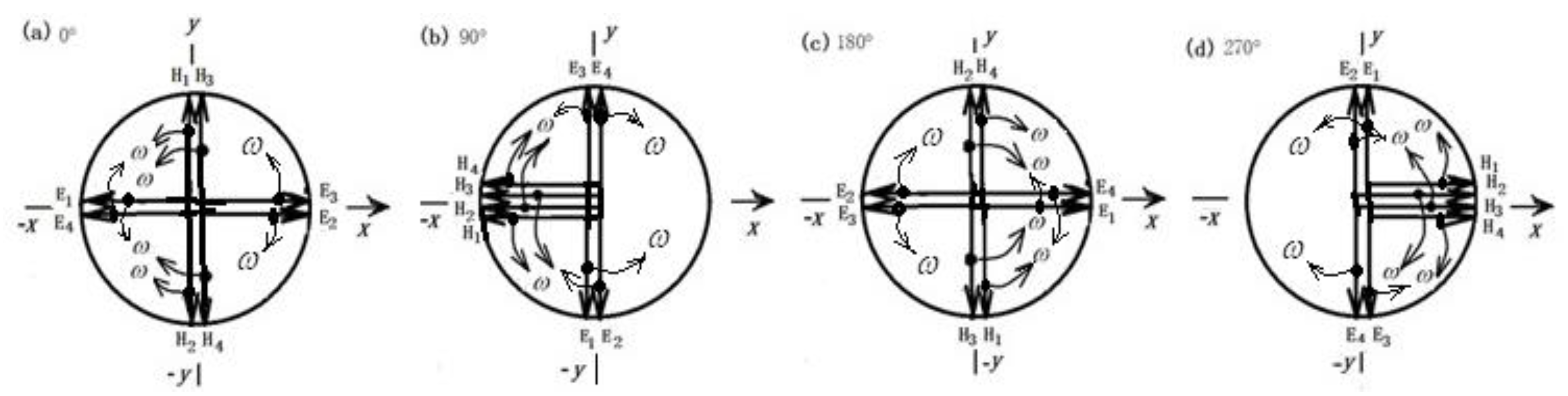
Figure 3.
The standing-wave 8-photon composite structure in a laser microcavity is composed of an incident 4-photon monomer(a) overlapping a reflected 4-photon monomer(b). (b)The electric field components of the reflected monomer are 180° out of phase with those of the incident monomer (subscript 3,4 in (b) correspond to 1,2 in (a), respectively), whereas the phase of the magnetic field components remains unchanged.
Figure 3.
The standing-wave 8-photon composite structure in a laser microcavity is composed of an incident 4-photon monomer(a) overlapping a reflected 4-photon monomer(b). (b)The electric field components of the reflected monomer are 180° out of phase with those of the incident monomer (subscript 3,4 in (b) correspond to 1,2 in (a), respectively), whereas the phase of the magnetic field components remains unchanged.

Figure 4.
The SWE4-P and the SWM4-P composites included in the SW8-P composite structure.
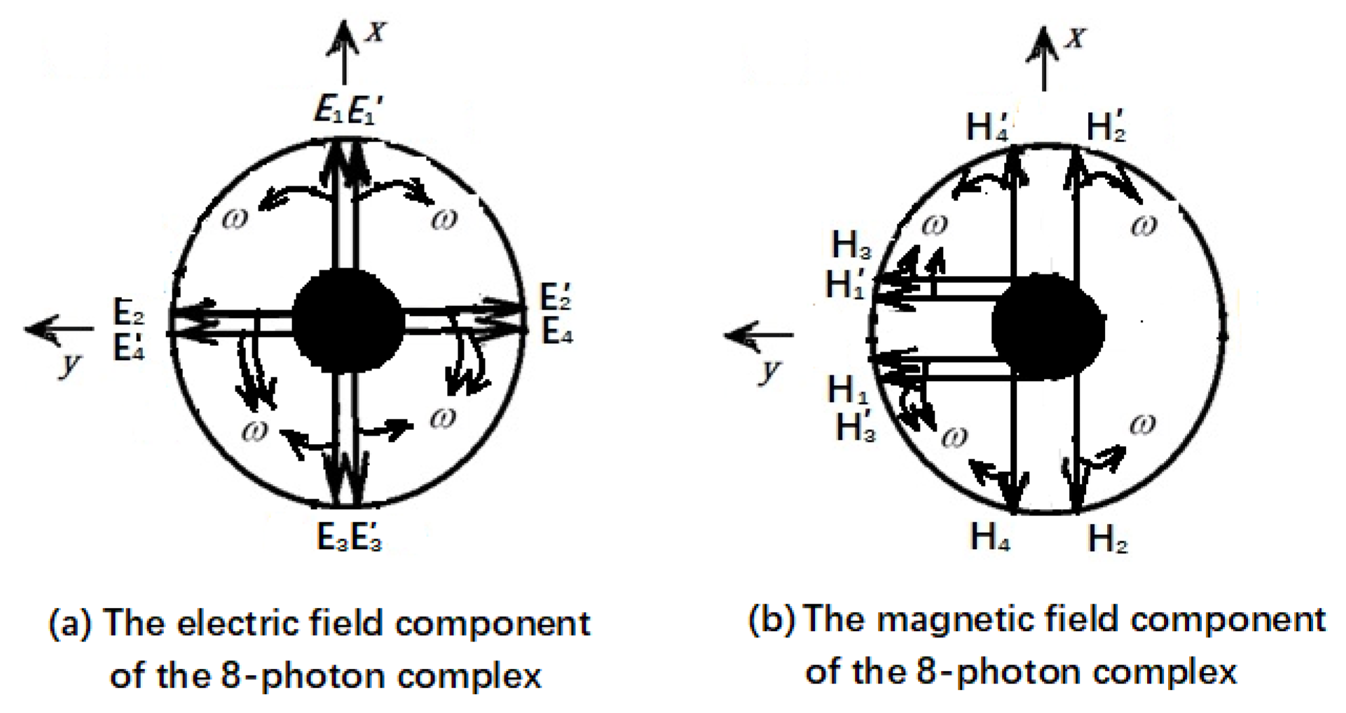
Figure 5.
The EM field distribution of the TM010 mode expressed by both Eq. (8) and Eq. (9). (a) The zeroth-order and first-order Bessel functions curves. (b) Schematic diagram of the electric field line and the magnetic field line of the TM010 mode in the MCR cavity.
Figure 5.
The EM field distribution of the TM010 mode expressed by both Eq. (8) and Eq. (9). (a) The zeroth-order and first-order Bessel functions curves. (b) Schematic diagram of the electric field line and the magnetic field line of the TM010 mode in the MCR cavity.
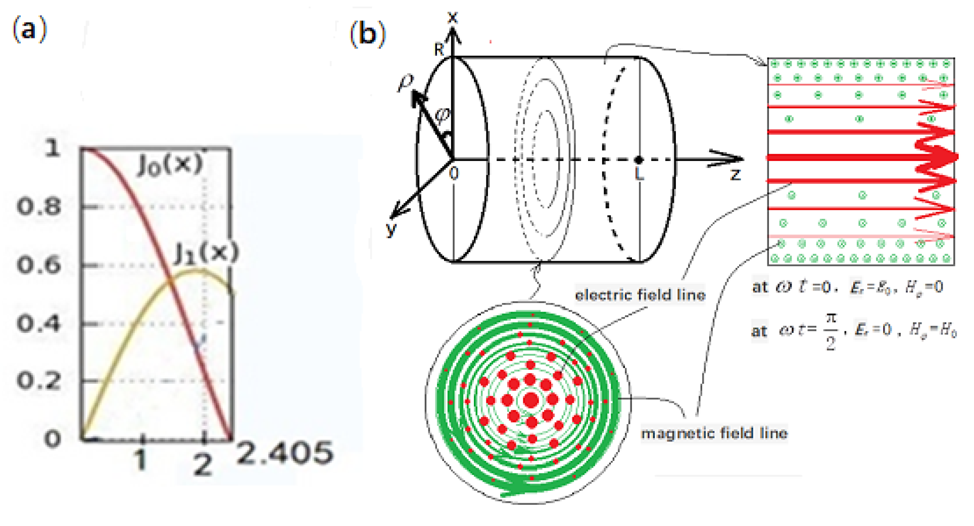
Figure 6.
The orientation of the Ez and Hφ of each cylindrical photon and the directions of the spin and wave-vector of each cylindrical photon in the same dV at ωt = 0° phase for the SWE4-P composite. The magnetic fields of the photon E1H1 and E2H2 are along -eφ, as shown in (a) and (b), respectively, but the spins are different, the former is right-spin, while the latter is left-spin, as shown in (a’) and (b’), respectively. Their wave vectors are along the eρ direction. The magnetic fields of the photon E3H3 and E4H4 are along eφ, as shown in (c) and (d), respectively. But their spins are different, the former is left-spin, and the latter is right-spin, as shown in (c’) and (d’), respectively. The wave vectors are along the -eρ direction.
Figure 6.
The orientation of the Ez and Hφ of each cylindrical photon and the directions of the spin and wave-vector of each cylindrical photon in the same dV at ωt = 0° phase for the SWE4-P composite. The magnetic fields of the photon E1H1 and E2H2 are along -eφ, as shown in (a) and (b), respectively, but the spins are different, the former is right-spin, while the latter is left-spin, as shown in (a’) and (b’), respectively. Their wave vectors are along the eρ direction. The magnetic fields of the photon E3H3 and E4H4 are along eφ, as shown in (c) and (d), respectively. But their spins are different, the former is left-spin, and the latter is right-spin, as shown in (c’) and (d’), respectively. The wave vectors are along the -eρ direction.
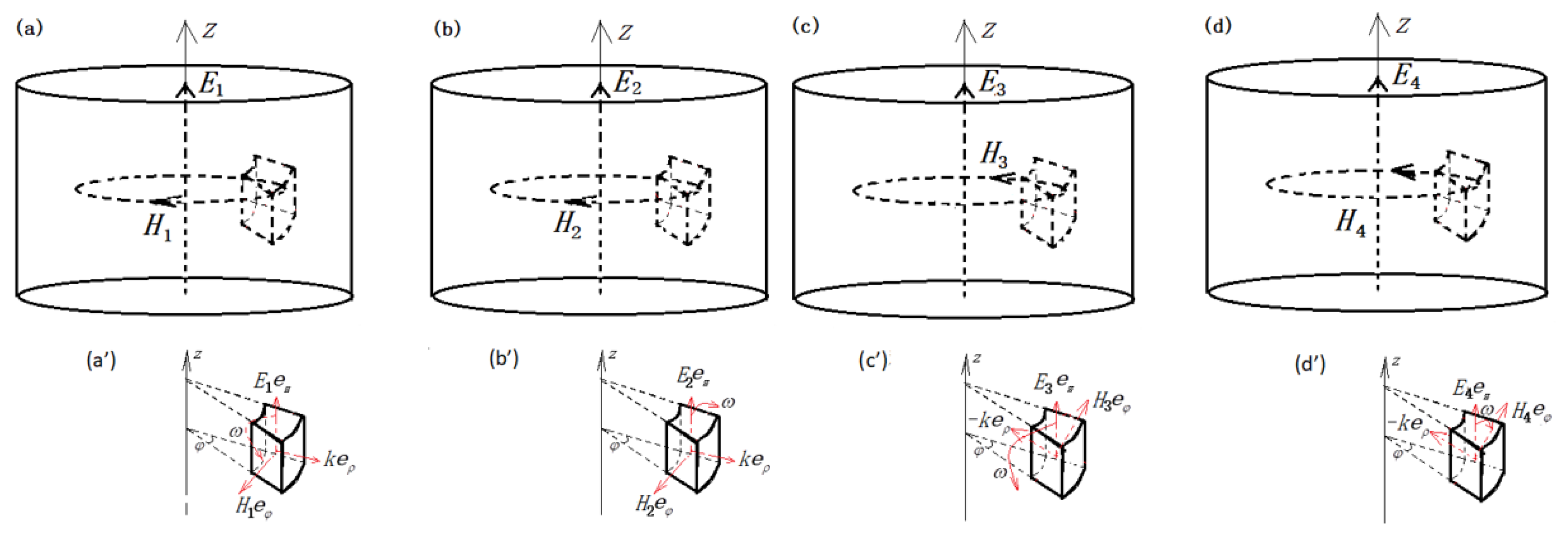
Figure 7.
The evolution of the electric- and magnetic-field vectors in a dV belong to the four photons (E1H1, E2H2, E3H3, E4H4) within the SWE4-P composite (displayed in the cylindrical surface (φ, z)). (a) at , the electric-field vector of the four photons is along the z axis; (b) at , the electric-field vectors of the four photons are pairwise cancel out to zero;(c) at , the electric-field vectors of the four photons are all along the -z axis; (d) at , the electric- field vector of the four photons are pairwise cancel out to zero. The cycle starts again and again.
Figure 7.
The evolution of the electric- and magnetic-field vectors in a dV belong to the four photons (E1H1, E2H2, E3H3, E4H4) within the SWE4-P composite (displayed in the cylindrical surface (φ, z)). (a) at , the electric-field vector of the four photons is along the z axis; (b) at , the electric-field vectors of the four photons are pairwise cancel out to zero;(c) at , the electric-field vectors of the four photons are all along the -z axis; (d) at , the electric- field vector of the four photons are pairwise cancel out to zero. The cycle starts again and again.
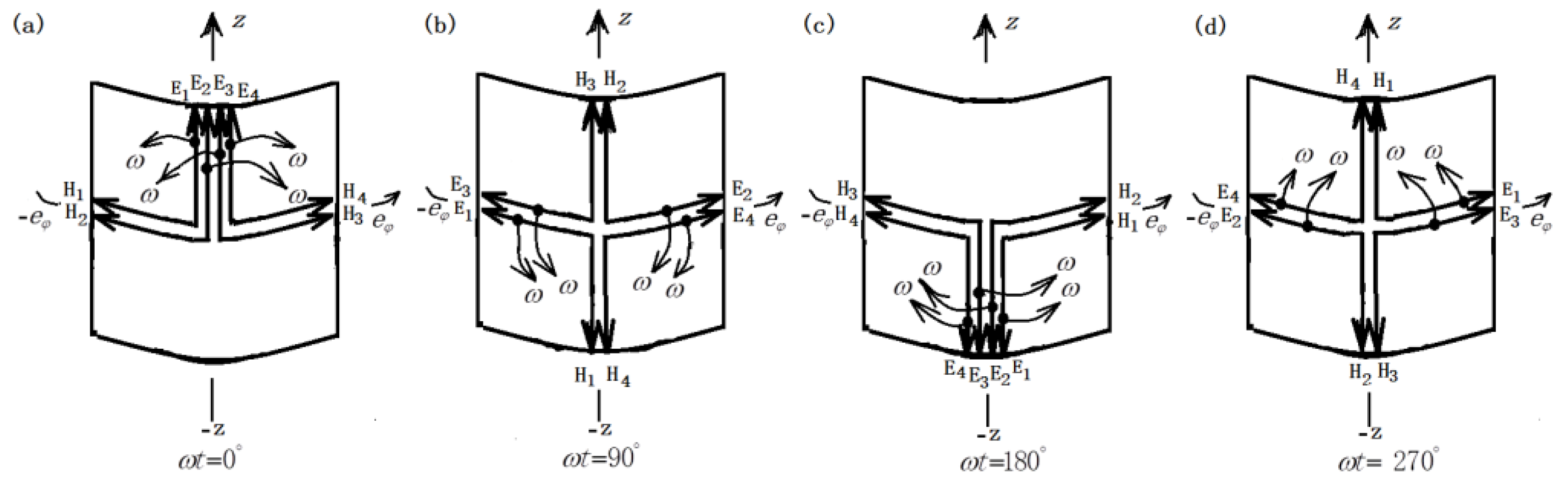
Figure 8.
The orientation of the Hφ and Ez of each cylindrical photon and the directions of the spin and wave-vector of each cylindrical photon in the same dV at ωt=90° phase for the SWM4-P composite. The total magnetic field directions of the four photon H1E1, H2E2, H3E3 and H4E4 are all along -eφ direction, their resultant electric field is zero in (a)–(d), but the spins are different, the photon H1E1, H3E3 are right-spin, as shown in (a’) and (c’), respectively. While the photon H2E2, H4E4 are left-spin, as shown in (b’) and (d’), respectively.
Figure 8.
The orientation of the Hφ and Ez of each cylindrical photon and the directions of the spin and wave-vector of each cylindrical photon in the same dV at ωt=90° phase for the SWM4-P composite. The total magnetic field directions of the four photon H1E1, H2E2, H3E3 and H4E4 are all along -eφ direction, their resultant electric field is zero in (a)–(d), but the spins are different, the photon H1E1, H3E3 are right-spin, as shown in (a’) and (c’), respectively. While the photon H2E2, H4E4 are left-spin, as shown in (b’) and (d’), respectively.
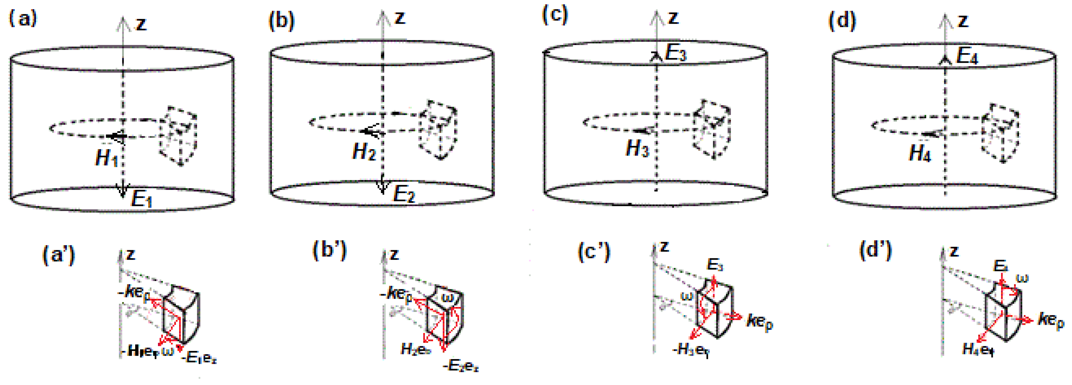
Figure 9.
The evolution of the electric and magnetic field vectors from four photons (H1E1, H2E2, H3E3, H4E4) in each dV of the SWM4-P composite over a period (displayed in the cylindrical surface (φ, z)). (a) at , the total magnetic field vectors of the four photons are along the axis, and pairwise cancel to zero; (b) at , the total magnetic field vectors of the four photons are all along the -eφ direction; (c) at , the total magnetic field vectors of the four photons are again along the axis, and pairwise cancel to zero; (d) at, the total magnetic field vectors of the four photons are all along the eφ direction. The cycle starts again and again. The photon differential volumes (a’), (b’), (c’), (d’) in Figure 8 only correspond to here (b).
Figure 9.
The evolution of the electric and magnetic field vectors from four photons (H1E1, H2E2, H3E3, H4E4) in each dV of the SWM4-P composite over a period (displayed in the cylindrical surface (φ, z)). (a) at , the total magnetic field vectors of the four photons are along the axis, and pairwise cancel to zero; (b) at , the total magnetic field vectors of the four photons are all along the -eφ direction; (c) at , the total magnetic field vectors of the four photons are again along the axis, and pairwise cancel to zero; (d) at, the total magnetic field vectors of the four photons are all along the eφ direction. The cycle starts again and again. The photon differential volumes (a’), (b’), (c’), (d’) in Figure 8 only correspond to here (b).

Disclaimer/Publisher’s Note: The statements, opinions and data contained in all publications are solely those of the individual author(s) and contributor(s) and not of MDPI and/or the editor(s). MDPI and/or the editor(s) disclaim responsibility for any injury to people or property resulting from any ideas, methods, instructions or products referred to in the content. |
© 2025 by the author. Licensee MDPI, Basel, Switzerland. This article is an open access article distributed under the terms and conditions of the Creative Commons Attribution (CC BY) license (https://creativecommons.org/licenses/by/4.0/).
Copyright: This open access article is published under a Creative Commons CC BY 4.0 license, which permit the free download, distribution, and reuse, provided that the author and preprint are cited in any reuse.


