
Submitted:
22 July 2025
Posted:
23 July 2025
You are already at the latest version
Abstract
The need for advanced, sustainable materials with improvement for flame resistance is critical in industries to be applied in such for construction and electronics. The epoxy has been widely used for these industries. While epoxy resin is valued for its durability, it has drawbacks due to flammability and low thermal stability. This effect on the final processing and application. This research addresses to overcome these limitations by incorporating nanocellulose, a renewable and biodegradable polymer derived from natural cellulose, to enhance the flame retardancy and thermal performance of epoxy compounds. Nanocellulose (CNC) was extracted through different steps such extractives removal, bleaching, mercerization and acid hydrolysis. This CNC was incorporated into epoxy with varying concentration (0.5% and 1.0%). After fabrication into epoxy composites, the samples were evaluated for flammability test using cone calorimetry and thermal stability test by thermogravimetric analysis (TGA). Preliminary results are promising, with the addition of 0.5% CNC/epoxy composite demonstrating a significant 17% reduction in peak heat release rate (pHRR) and total heat release rate (HRR), indicating substantial improvements in flame resistance without compromising the material's structural integrity. This research confirms the potential of nanocellulose as a high-performance and greener materials that can withstand the demands of fire-sensitive environments.
Keywords:
biocomposite
; nanocellulose
; epoxy
; flame retardant
; thermal stability
1. Introduction
In the last few years, the polymeric composites have shown a promising result in replacing many conventional materials for various applications. The development of these composites is linked to the constituents and contents that determine their interfaces and linkages. Epoxy polymer is among a thermoset that widely utilize for many applications such as for structural, coating and adhesive due to its advantage properties such as excellent mechanical performance, corrosion and chemical resistances, great electrical insulation and good adhesion with various substrates [1]. Epoxy polymer has a wide range of properties depending on the curing agent, curing cycles and molecular structure [2]. Conventional epoxy polymer (bisphenol A based-epoxy) was synthesized by Pierre Castan in Switzerland and Sylvan Greenlee in United States in 1936 [3]. After a few attempts, the commercial mass production of epoxy was beginning in 1947 with following some qualities improvement was done from 1955 to 1965 [4].
A typical application of epoxy resin is using as matrix to form a composite material including nanocomposite materials. Epoxy resin is compatible with various nano based materials such as nano silica, carbon-based nanomaterials, nano clay to name a few. Despite of advantages that this resin has, there also has some drawbacks in terms of limited petrochemical resources, environmental issues and cost of production that limits the use of this resin [5]. Many researches have been conducted to develop more sustainable and eco-friendly epoxy composites with added biomass and bio-based materials such as cellulose into epoxy [6,7].
Cellulose is a type of polysaccharide, assembled from glucose monomer units and the most abundant natural biopolymer with around 40%-90% can be extracted from pant or biomass depend on the sources. Cotton is considered 90% built-up from cellulose source [8]. Another source for cellulose is Kenaf (Hibiscus cannabinus) that has been planted commercially as a commodity crop in some countries such as Malaysia, China, India and Brazil [9]. The cellulose sources can be classified as from woody and non-woody plant-based materials [10]. The cellulose chains are primarily made from amorphous and crystalline regions. The amorphous region can be completely removed and break down to form nano sized cellulose or known as nano crystalline cellulose (CNC)[11]. The CNC has a high crystallinity region that contributed to overall performance such as mechanical properties, thermal stability and flame retardancy [12,13]. This CNC can be used as reinforcement in epoxy composites to reduce the dependency of epoxy polymer, and overcome some limitations that commonly has on epoxy regarding low thermal stability as well as the flame resistance [14]. Other than these properties, CNC has benefits for surface functionalization to design and tailoring with different final applications such as for automotive, packaging, electronic and coating, among others. Moreover, when the CNC has been modified, the adhesion between fillers and matrices would become improve and achieving better properties [15]. The main drawbacks of CNC are related to hydrophilic properties in nature. Thus, the composite is susceptible to moisture absorption, weaken the adhesion and reduce the stress transfer from matrix to the reinforcement [16]. This property also tends to make CNC to agglomerate with each other when added into polymer matrix. The functionalization can be done in many ways but the chemical functionalization is the most common ways to improve the properties. The chemical functionalization namely amination, esterification, oxidation, etherification is among a typical modification on CNC surface [17].
Most of the studies conducted using cellulose in microscale as reinforcement in different polymer matrices to study the mechanical properties; less study has been focused on thermal stability and flame retardancy of composites to be utilized in different high-end applications. In this study, we aim to investigate the thermal stability and flammability of cellulose nanocrystals (CNC) reinforced with epoxy as a composite. We extracted the CNC from cotton linter cellulose. Then, the CNC was reinforced with epoxy to form epoxy composites with different CNC concentrations (0.5% wt and 1.0% wt). The different characterizations were conducted, such as TEM, XRD, FTIR, and EDX. The flammability test for epoxy composite was performed using cone calorimetry, and the thermal stability of epoxy composite was performed by using thermogravimetry analysis (TGA). Then, SEM and FTIR were used to evaluate the samples before and after cone calorimetry tests were conducted. The CNC epoxy composite can be used for final applications such as coating and biocomposite applications.
2. Materials and Methods
2.1. Materials
Cotton linter was bought from a local supplier and came in the length of an average 12 mm and a diameter of size 20 ɥm, Chemicals namely, hydrochloric acid (HCl), epoxy and hardener, all were purchased from local supplier and used without further purification.
2.2. Cellulose Nanocrystals Hydrolysis
5 g of cotton linter cellulose was placed in a round-bottom flask and surrounded by an ice bath within a large 1 L beaker. HCl acid was incrementally added, drop by drop, until a concentration of 5 M was attained. The ice bath was thereafter removed, and the bottom flask was preheated until it reached 100 ℃, maintained for 60 minutes during the hydrolysis stage with continuous stirring at 500 rpm. Upon completion of the hydrolysis procedure, the mixture was immediately quenched with ice tubes to halt the reaction, followed by multiple rinses with distilled water and centrifugation to eliminate the unreacted acid. The mixture was subsequently filtered, placed in a dialysis tube, and immersed in distilled water until it attained a pH of 7. The final suspension was dried using a freeze drier prior to its application in subsequent operations. The quantity of CNC acquired was 2 g. The optimal parameters were determined based on the preliminary experiment done by Taib et al. [18].
2.3. Composite Fabrication
The epoxy composites were prepared using the solution casting method. Initially, the CNC at concentrations of 0, 0.5%, and 1.0% was combined with epoxy and hardener in a beaker through stirring. The solution was subsequently poured into a silicon mold measuring 100 x 100 x 30 mm3 and allowed to cure overnight for the samples. The samples were labeled as neat epoxy, 0.5% CNC/epoxy, and 1.0% CNC/epoxy, respectively.
2.4. Characterization
2.4.1. Transmission Electron Microscopy (TEM)
First, 0.1% of DI water was used to dilute the CNC sample. The sample then was sonicated using ultrasonicate for 30 minutes to make sure the sample was not agglomerated. Next, using a plastic dropper, one drop for each sample was placed onto a copper grid. After that, the sample was allowed to dry at room temperature for 60 seconds. Filter paper was used to get rid of the excess solution. With an accelerating voltage of 120 kV, a TEM microscope (Zeiss Libra 120, Carl Zeiss NTS GmBH) was used to capture an image of the size and structure of the sample.
2.4.2. Fourier Transform Infrared Spectroscopy (FTIR)
Fourier transform infrared spectroscopy (FTIR) equipped with ATR accessory were used to study the functional groups of the neat epoxy and its composites that were carried out from 4000 cm-1 to 600 cm-1 using FTIR (PerkinElmer) instrument.
2.4.3. X-Ray Diffraction (XRD)
X-ray diffraction patterns were recorded on a PANalytical X’ Pert PRO MPD diffraction system for OPT and CNC samples in order to examine the changes in crystallinity of the material before and after acid hydrolysis treatment. The Segal equation in Equation (1) was used to calculate the crystallinity index (CrI) for all samples [19]. The analysis and peak determination were carried out using PANalytical HighScore Plus 3.0d software.
2.4.4. Thermogravimetry Analysis (TGA)
The thermal stability of neat epoxy and its composites were investigated using thermogravimetry analysis, TGA Q-500 (TA Instruments, USA). Approximately 10 mg of each sample was weighed in a pan and operated under a continuous flux of nitrogen gas (50 mL/min). All the samples were heated from room temperature to 900 ℃, with a 10 ℃/min ramp.
2.4.5. Flame Retardancy
The flame retardant evaluation on epoxy and its composites was conducted using cone calorimeter model GD-ISO5660B-M by following the procedures of ISO 5660 under a heat flux of 50 kW/m2 with the sample size of 100.0×100.0×3.0 mm3.
2.4.6. Scanning Electron Microscopy (SEM)
The microstructures and morphologies of CNC and their composites were observed by using a scanning electron microscopy (SEM) instrument (SU3500, Hitachi, Tokyo, Japan). The samples were spatter coated with thin layer of gold to avoid charges. Accelerating voltage at 20 kV in low vacuum was used to avoid samples burning.
2.4.7. Energy Dispersive X-Ray Analysis (EDX)
The EDX analysis was conducted on CNC. Initially, the sample was weighed, approximately 0.05 g, and then placed on a double tab that was conductive with carbon. Following this, the samples underwent a gold sputter coating to reduce charging effects and distortion. The images were acquired using a scanning electron microscope fitted with an Oxford Instruments X-max 50 mm2 dispersive X-ray detector, functioning at an accelerating voltage of 5 kV in a high vacuum environment.
3. Results and Discussion
3.1. Transmission Electron Microscopy (TEM)
Figure 1 presents the TEM micrographs of CNC. The CNC exhibited a platelet-like and spherical shapes, with agglomeration observed among the CNC particles. The CNC has been verified to exhibit nano-scale widths and micro-scale lengths. The TEM analysis revealed that the CNC had a length of 178.12 ± 74.18 nm and a width of 91.22 ± 35.58 nm, resulting in an aspect ratio of 2.06 ± 0.65.
3.2. Xray Diffraction (XRD)
The XRD pattern in Figure 2 shows a cellulose nanocrystal. The CNC shows a cellulose I typical structure [22]. The crystallinity of CNC may result in a decreased reinforcing capability within polymer composites [23]. The crystalline structure of CNC significantly influences its reinforcing effects and ensures that it maintains of this property when incorporated and reinforced within a polymer matrix. Figure 2 illustrates the observed diffraction peaks at 2θ angles of approximately 14.5, 16.3, 20.4, 22.7, and 34.3, which correspond to the reflection planes of cellulose I, namely [1-10], [110], [012], [200], and [004], respectively [24]. The findings demonstrated that the crystalline structure remained intact, exhibiting the typical cellulose configuration, with a recorded crystallinity index of 84.79%, calculated using the Segal equation as outlined in Eq.1.
3.3. Energy Dispersive X-Ray Spectroscopy (EDX)
The EDX spectrum of the CNC is shown in Figure 3. The CNC consists of the elements carbon (C) and oxygen (O), which are its main components. The Cl was likely originated from small traces of hydrochloric acid (HCl).
3.4. Thermogravimetric Analysis (TGA)
The thermal stability and decomposition of neat epoxy and its composites were assessed through TGA analysis. The information is summarized in Table 1, obtained from the TGA and DTG thermograms presented in Figures 4(a) and 4(b). Two distinct peaks were observed for the decomposition of neat epoxy and its composites. The area below 150 ℃ was associated with the elimination of water presence and volatile organic compounds [25]. In the temperature range of 300 ℃ to 500 ℃, the degradation peaks of the composites exhibited overlap, with the onset temperature for neat epoxy recorded at 314 ℃, while the 1.0% CNC/epoxy showed an onset temperature of 329 ℃. The presence of CNC exhibiting a high crystallinity index may explain the elevated onset degradation observed in the epoxy composite. High energy adsorption is required in order allowing for disarrangement prior to further degradation. Another reason is an increase in cross-linking density of epoxy resin [26]. The maximum degradation temperature of neat epoxy was found to be 375 ℃; however, upon the incorporation of CNC, this maximum degradation temperature decreased to 369 ℃ for the 1.0% CNC/epoxy. The increase in the quantity of surface area exposure at higher levels of CNC content may be responsible for the decrease in thermal properties observed at 1.0% CNC/epoxy [13]. The formation of porous structures following the thermal degradation of CNC can lead to a reduction in thermal conductivity [27].
3.5. Flame Retardancy
Cone calorimeter tests represent a highly effective method for assessing the flammability of composites in conditions that simulate real burning scenarios. Figures 5(a) to (b) shows the curves for time to ignition (TTI), total heat release (THR), heat release rate (HRR), and total smoke production (TSP) for neat epoxy and its composites, with the key details listed in Table 2. The time to ignition, or TTI, plays a crucial role in assessing the delay before a fire begins to burn on a sample. The highest value for TTI was recorded for 1.0 wt% CNC/epoxy within 20 s followed by 0.5% CNC/epoxy (17 s) and neat epoxy (13 s). The highest peak heat release rate (pHRR) was recorded for neat epoxy which shows a very poor flame resistance. With the addition of 0.5 wt% and 1.0 wt% of CNC within epoxy reduced the pHRR values to 537.56 kW/m2 and 537.02 kW/m2, respectively as compared with neat epoxy that was 651.61 kW/m2. This suggested that the addition of 0.5 wt% of CNC into epoxy was enough to reduce the flammability on epoxy from continue to propagate. This reduction was around 17% for both epoxy composites as compared to neat epoxy. This suggested the better flame resistance. The total smoke production (TSP) shows a minimal smoke was released for neat epoxy during combustion process. The addition of CNC leads to increase the smoke production due to formation of char layer that prevented the flame from penetrating. TSP value for 0.5 wt% CNC-epoxy was 10.3 m2 and 1.0 wt% CNC-epoxy was 10.5 m2, both were higher than neat epoxy that was 9.2 m2. This suggested that the production of smoke supressed the fire on the samples from further burning. The main mechanism for CNC is promoting the formation of char layer in epoxy surface layer thus hindering the heat and flame from the char areas due to absence of oxygen gases. This prevented the inner layer of epoxy from further burning thus integrity of structure of epoxy not totally compromise. This in agreement with a study conducted by Sun et al. [28] stated that with addition of additive would promote the char formation and hindered the penetration of flame to the inner part of material.
3.6. Morphology of Char Residues Using Scanning Electron Microscopy (SEM)
Figures 6(a) to 6(g) display the SEM cross section and structure of neat epoxy, 0.5% CNC-epoxy, and 1.0% CNC-epoxy, both before and after the cone calorimetry test. The results of the cross section of the samples indicated the excellent adhesion of CNCs and epoxy thermoset as shown in Figure 6(a). Furthermore, the SEM images of fractures surfaces of CNCs composites with varying loading percentages are shown in Figure 6(c) and Figure 6(e), for 0.5% and 1.0% of CNC reinforced epoxy, the fiber and matrix have a good adhesion and no porosity. It appeared to notice and have some cracks, voids and fissures for all samples after the cone calorimetry test. The 0.5%(Figure 6(d)) and 1.0% CNC/epoxy (Figure 6(g)) show a continuous and denser char layer with some cracks were observed at higher level of magnification. The denser char layer forms a protective insulator against flame. The oxygen gas in this area is nil, and the flame could not penetrate it because the elements needed for fire to survive are not complete. The addition of 0.5% and 1.0% CNC into epoxy enhances the char residue formation which protecting the epoxy matrix and result in lower heat release. This was in agreement with a study by Wang et al. [29] in epoxy nanocomposites that added nano additive in the form of carbon nanotubes that enhanced the char formation which protect the inner layer of polymer from further combustion.
3.7. Fourier Transform Infrared (FTIR)
Fourier transform Infrared spectroscopic analysis was used to identify the mechanism of both epoxy monomer and curing agent on CNC. Initially, the interaction between amine curing agent and CNC was investigated. Figure 7 shows the FTIR for epoxy control, 0.5% CNC/epoxy and 1.0% CNC/epoxy before and after cone calorimeter tests were conducted. For epoxy control showed the typical broad peak around 3500-3000 cm-1, which attributed of OH stretching vibration of the OH groups [30]. The C-H group was observed around 2800-2900 cm-1 [31]. The CH2 was appeared at 2324 cm-1 and 2361 cm-1. The C=O peak was observed at 1730 cm-1. This peak was indicated with the appearance of ester carbonyl group [32]. The amine groups for hardener used in epoxy composites was appeared at 1595 cm-1 and 1505 cm-1, respectively. These peaks were attributed to NH bend found in primary amides and the amide linkages attributed to presence of C=O [33]. The peak at 2964 cm-1 was appeared at 0.5% CNC/epoxy and 1.0% CNC/epoxy corresponding to C-H group in cellulose, this followed by existence of peak 2361 cm-1. The formation of carbon compound was observed with existence of peaks at 1550 to 1600 cm-1 and at peak 942 cm-1 after cone calorimetry test [34].
4. Conclusions
The present study examines the effect on thermal stability and flame retardancy following the incorporation of low loading reinforcement of cellulose nanocrystals (CNC) in epoxy composites. The CNC exhibits a cellulose I crystal structure, characterized by a crystallinity index of 84.79%. This resulted in the integration of high crystallinity CNC into epoxy, showcasing a notable degree of intramolecular hydrogen bonding and distinct crystal structure properties. The incorporation of CNC at low loading levels of up to 1.0% facilitated improved dispersion and a homogeneous mixture within the polymer matrix. CNCs with a lower aspect ratio improve the nucleation phenomenon throughout the crystallization process. The thermal stability of epoxy reinforced with CNC is significantly altered after the addition of 1% CNC, attributed to the crystalline structure of CNC and the enhancement of crosslinking density within the polymer matrix. The addition of CNC resulted in enhanced flame retardancy, with 1.0% CNC yielding the highest improvement in epoxy, promoting a char layer that served as an effective barrier. The additional investigation was validated through SEM and FTIR analyses. This study successfully produced CNC reinforced epoxy composites that exhibit superior thermal and flame-retardant performances when compared to the epoxy without any additives. Additionally, further research can be conducted in various fields including electrical properties, chemical resistance, environmental effects, and the industrial utilization of this kind of composite.
Author Contributions
H.A.; Investigation, writing—original draft preparation. M.N.AM.T.; writing—original draft preparation, writing—review and editing, supervision. T.A.S.; writing—review and editing.
Funding
This research received no external funding
Institutional Review Board Statement
Not applicable
Data Availability Statement
Data will be made available upon request.
Acknowledgments
The authors would like to thank to Universiti Malaya for technical supports. Special thanks to King Abdul Aziz Model Schools for sponsorship of Mawhiba program for Ms H. Albaqi and King fahd University of Petroleum and Minerals for provided a place for Mawhiba project to take place and Dr Saji Viswanathan S. for providing a sponsorship of the publication.
Conflicts of Interest
The authors declare no conflicts of interest.
Abbreviations
The following abbreviations are used in this manuscript:
| CNC | Cellulose nanocrystals |
| TGA | Thermogravimetry analysis |
| pHRR | Peak heat release rate |
| HRR | Heat release rate |
| TEM | Transmission electron microscopy |
| XRD | X-ray diffraction |
| FTIR | Fourier transform infrared |
| EDX | Energy dispersive X-ray spectroscopy |
| HCl | Hydrochloric acid |
References
- Guo, Q. Thermosets: structure, properties, and applications; Woodhead Publishing: 2017.
- Aziz, T.; Haq, F.; Farid, A.; Cheng, L.; Chuah, L.F.; Bokhari, A.; Mubashir, M.; Tang, D.Y.Y.; Show, P.L. The epoxy resin system: function and role of curing agents. Carbon Letters 2024, 34, 477–494. [Google Scholar] [CrossRef]
- Parameswaranpillai, J.; Pulikkalparambil, H.; Rangappa, S.M.; Siengchin, S. Epoxy composites; Wiley Online Library: 2021.
- Feldman, D. Polymer history. Designed monomers and polymers 2008, 11, 1–15. [Google Scholar] [CrossRef]
- Sasidharan, S.; Anand, A. Epoxy-based hybrid structural composites with nanofillers: a review. Industrial & Engineering Chemistry Research 2020, 59, 12617–12631. [Google Scholar] [CrossRef]
- Santulli, C. Utilization of Renewable Biomass and Waste Materials for Production of Environmentally-Friendly, Bio-based Composites. In Eco-Friendly Adhesives for Wood and Natural Fiber Composites: Characterization, Fabrication and Applications; Springer: 2021; pp. 131-145.
- Aziz, T.; Fan, H.; Zhang, X.; Khan, F.U.; Fahad, S.; Ullah, A. Adhesive properties of bio-based epoxy resin reinforced by cellulose nanocrystal additives. Journal of Polymer Engineering 2020, 40, 314–320. [Google Scholar] [CrossRef]
- Dassanayake, R.S.; Abidi, N. Cellulose Aerogels: Preparation, Characterization and Applications. Cotton Fibres 2017, 207. [Google Scholar]
- Kamal, I.B. Kenaf for biocomposite: an overview. Journal of Science and Technology 2014, 6. [Google Scholar]
- Pennells, J.; Godwin, I.D.; Amiralian, N.; Martin, D.J. Trends in the production of cellulose nanofibers from non-wood sources. Cellulose 2020, 27, 575–593. [Google Scholar] [CrossRef]
- Trache, D.; Hussin, M.H.; Haafiz, M.M.; Thakur, V.K. Recent progress in cellulose nanocrystals: sources and production. Nanoscale 2017, 9, 1763–1786. [Google Scholar] [CrossRef] [PubMed]
- Taib, M.N.A.M.; Hamidon, T.S.; Garba, Z.N.; Trache, D.; Uyama, H.; Hussin, M.H. Recent progress in cellulose-based composites towards flame retardancy applications. Polymer 2022, 244, 124677. [Google Scholar] [CrossRef]
- Taib, M.N.A.M.; Yee, T.S.; Trache, D.; Hazwan Hussin, M. Modification on nanocellulose extracted from kenaf (Hibiscus cannabinus) with 3-aminopropyltriethoxysilane for thermal stability in poly (vinyl alcohol) thin film composites. Cellulose 2024, 31, 997–1015. [Google Scholar] [CrossRef]
- Yang, Y.; Chen, W.; Li, Z.; Huang, G.; Wu, G. Efficient flame retardancy, good thermal stability, mechanical enhancement, and transparency of DOPO-conjugated structure compound on epoxy resin. Chemical Engineering Journal 2022, 450, 138424. [Google Scholar] [CrossRef]
- Antony Jose, S.; Cowan, N.; Davidson, M.; Godina, G.; Smith, I.; Xin, J.; Menezes, P.L. A comprehensive review on cellulose Nanofibers, nanomaterials, and composites: Manufacturing, properties, and applications. Nanomaterials 2025, 15, 356. [Google Scholar] [CrossRef] [PubMed]
- Olonisakin, K.; Fan, M.; Xin-Xiang, Z.; Ran, L.; Lin, W.; Zhang, W.; Wenbin, Y. Key improvements in interfacial adhesion and dispersion of fibers/fillers in polymer matrix composites; focus on pla matrix composites. Composite Interfaces 2022, 29, 1071–1120. [Google Scholar] [CrossRef]
- Abu Hasan Howlader, M. Preparation, functionalization and derivation of nanocrystalline cellulose. 2015.
- Taib, M.; Yehye, W.A.; Julkapli, N.M. Synthesis and characterization of nanocrystalline cellulose as reinforcement in nitrile butadiene rubber composites. Cellul. Chem. Technol 2020, 54, 11–25. [Google Scholar] [CrossRef]
- Segal, L.; Creely, J.J.; Martin, A.E.; Conrad, C.M. An Empirical Method for Estimating the Degree of Crystallinity of Native Cellulose Using the X-Ray Diffractometer. Textile Research Journal 1959, 29, 786–794. [Google Scholar] [CrossRef]
- French, A.D. Idealized powder diffraction patterns for cellulose polymorphs. Cellulose 2014, 21, 885–896. [Google Scholar] [CrossRef]
- Azubuike, C.P.; Rodríguez, H.; Okhamafe, A.O.; Rogers, R.D. Physicochemical properties of maize cob cellulose powders reconstituted from ionic liquid solution. Cellulose 2012, 19, 425–433. [Google Scholar] [CrossRef]
- Taib, M.N.A.M.; Yehye, W.A.; Julkapli, N.M.; Hamid, S.B.O.A. Influence of hydrophobicity of acetylated nanocellulose on the mechanical performance of nitrile butadiene rubber (NBR) composites. Fibers and Polymers 2018, 19, 383–392. [Google Scholar] [CrossRef]
- Ferreira, F.; Pinheiro, I.; Gouveia, R.; Thim, G.; Lona, L. Functionalized cellulose nanocrystals as reinforcement in biodegradable polymer nanocomposites. Polymer composites 2018, 39, E9–E29. [Google Scholar] [CrossRef]
- Stanciu, M.-C.; Tanasă, F.; Teacă, C.-A. Crystallinity Changes in Modified Cellulose Substrates Evidenced by Spectral and X-Ray Diffraction Data. Polysaccharides 2025, 6, 30. [Google Scholar] [CrossRef]
- Conti Silva, J.A.; Walton, H.; Dever, S.; Kardel, K.; Martins Lacerda, T.; Lopes Quirino, R. Itaconic Anhydride as a Green Compatibilizer in composites prepared by the reinforcement of a Tung Oil-based Thermosetting Resin with Miscanthus, Pine Wood, or Algae Biomass. Coatings 2022, 13, 25. [Google Scholar] [CrossRef]
- Kumar, S.; Prasad, L.; Bijlwan, P.P.; Yadav, A. Thermogravimetric analysis of lignocellulosic leaf-based fiber-reinforced thermosets polymer composites: an overview. Biomass Conversion and Biorefinery 2024, 14, 12673–12698. [Google Scholar] [CrossRef]
- Antlauf, M.; Andersson, O. Thermal Conductivity of Porous and Dense Networks of Cellulose Nanocrystals. Macromolecules 2022, 55, 5326–5331. [Google Scholar] [CrossRef]
- Sun, Z.; Hou, Y.; Hu, Y.; Hu, W. Effect of additive phosphorus-nitrogen containing flame retardant on char formation and flame retardancy of epoxy resin. Materials Chemistry and Physics 2018, 214, 154–164. [Google Scholar] [CrossRef]
- Wang, J. Synthesis and characterization of flame-retardant-wrapped carbon nanotubes and its flame retardancy in epoxy nanocomposites. Polymers and Polymer Composites 2021, 29, S835–S843. [Google Scholar] [CrossRef]
- González, M.G.; Cabanelas, J.C.; Baselga, J. Applications of FTIR on epoxy resins-identification, monitoring the curing process, phase separation and water uptake. Infrared spectroscopy-materials science, engineering and technology 2012, 2, 261–284. [Google Scholar]
- Liu, J.; Chen, K.; Zhang, Y.; Zhou, L.; Wang, F.; Xiang, X.; Wu, H. Study on the chemical bonding at the interface between epoxy primer and polyurethane topcoat. Progress in Organic Coatings 2024, 196, 108677. [Google Scholar] [CrossRef]
- Heng, Z.; Chen, Y.; Zou, H.; Liang, M. Spectroscopic analysis of epoxy/rubber blends. In Handbook of Epoxy Blends; Springer: 2017; pp. 147-184.
- Khajouei, M.; Pouresmaeel-Selakjani, P.; Latifi, M. Spectroscopy and Other Miscellaneous Techniques for the Characterization of Bio-epoxy Polymers, Their Blends, and Composites. Bio-Based Epoxy Polymers, Blends and Composites: Synthesis, Properties, Characterization and Applications 2021, 267-281.
- Kareem, A.A.; Rasheed, H.K. Electrical and thermal characteristics of MWCNTs modified carbon fiber/epoxy composite films. Materials Science-Poland 2019, 37, 622–627. [Google Scholar] [CrossRef]
Figure 1.
TEM images of prepared cellulose nanocrystals (CNC).
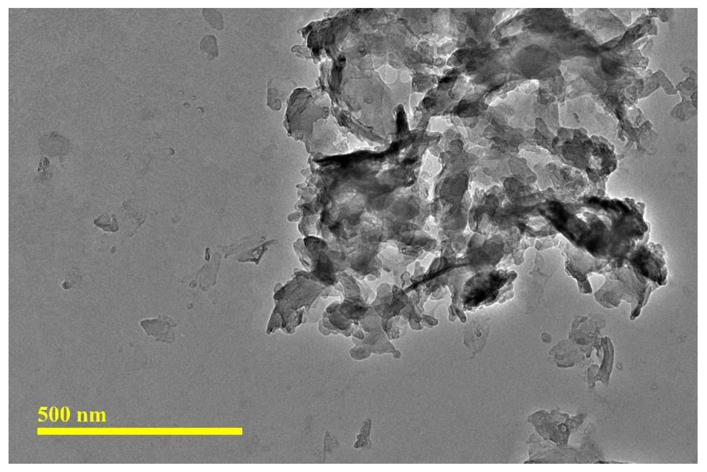
Figure 2.
XRD diffraction spectra of cellulose nanocrystals (CNC).
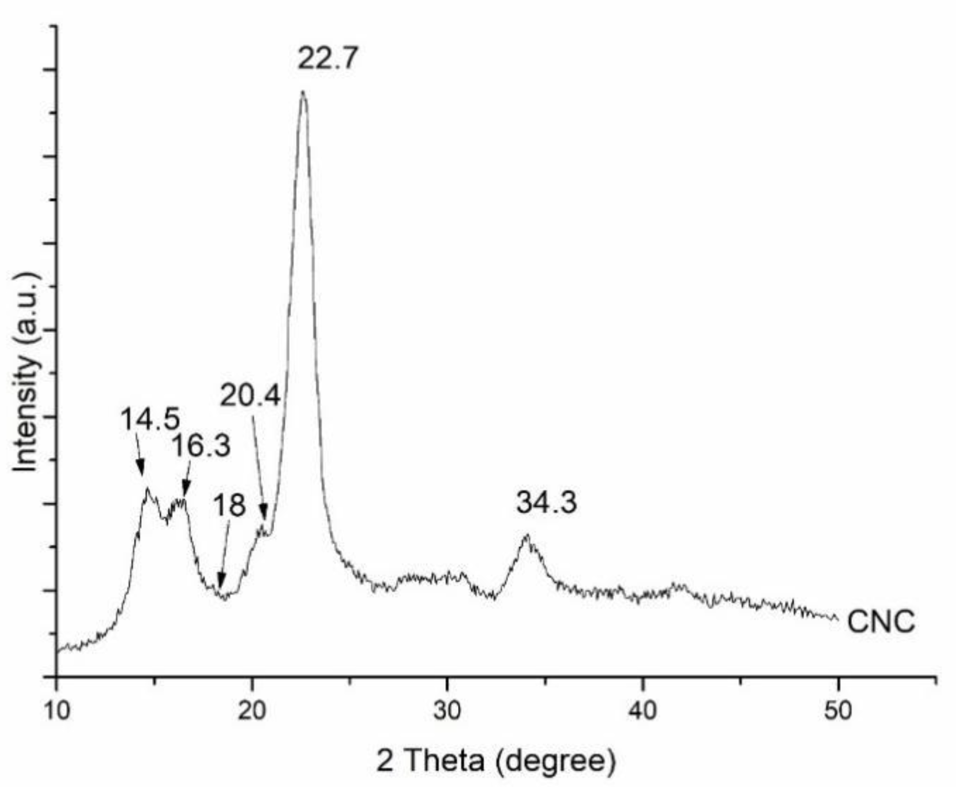
Figure 3.
EDX spectra and elemental identification of cellulose nanocrystals (CNC).
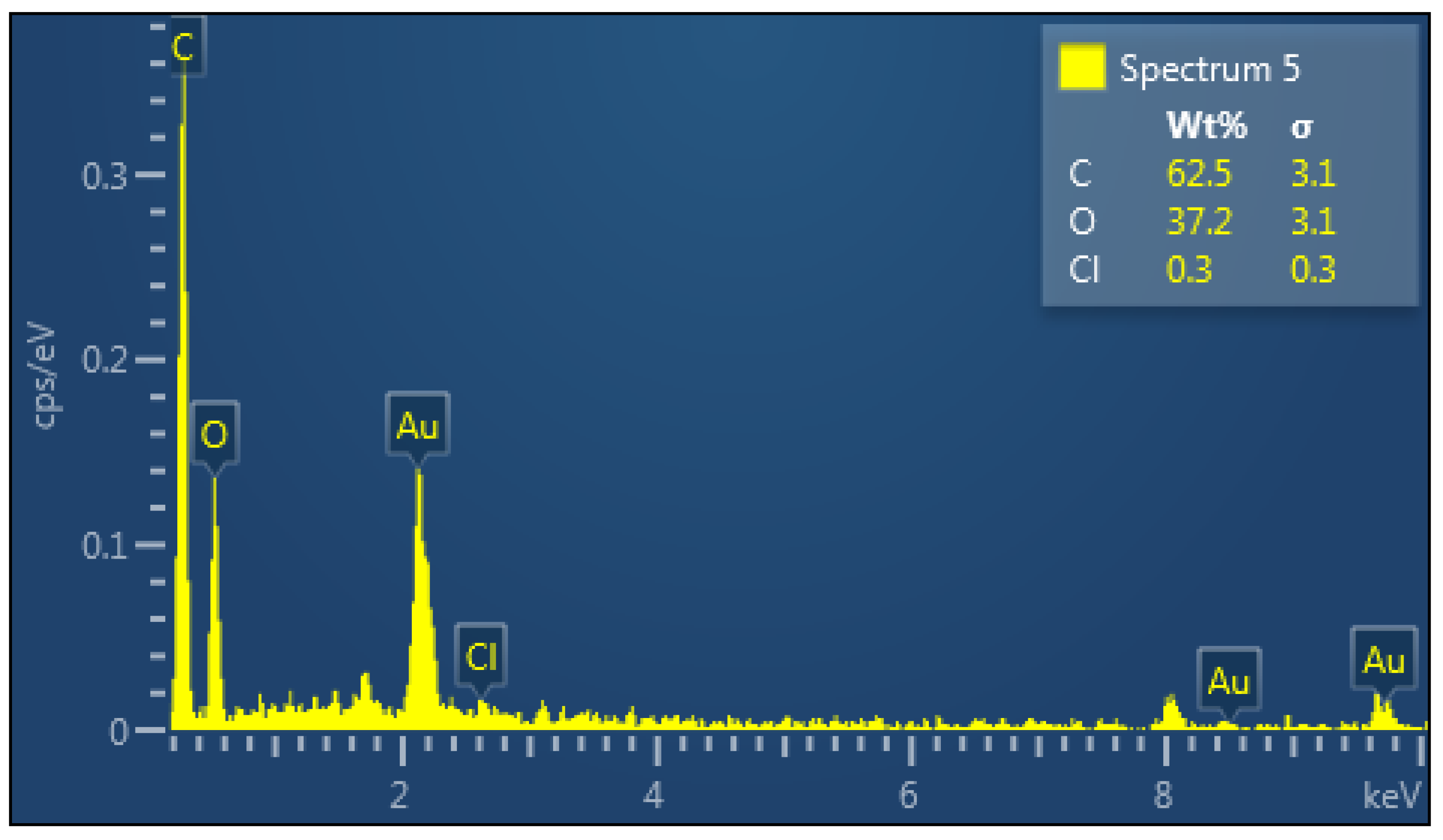
Figure 4.
(a) TGA; (b) DTG for neat epoxy and 1% CNC/epoxy.
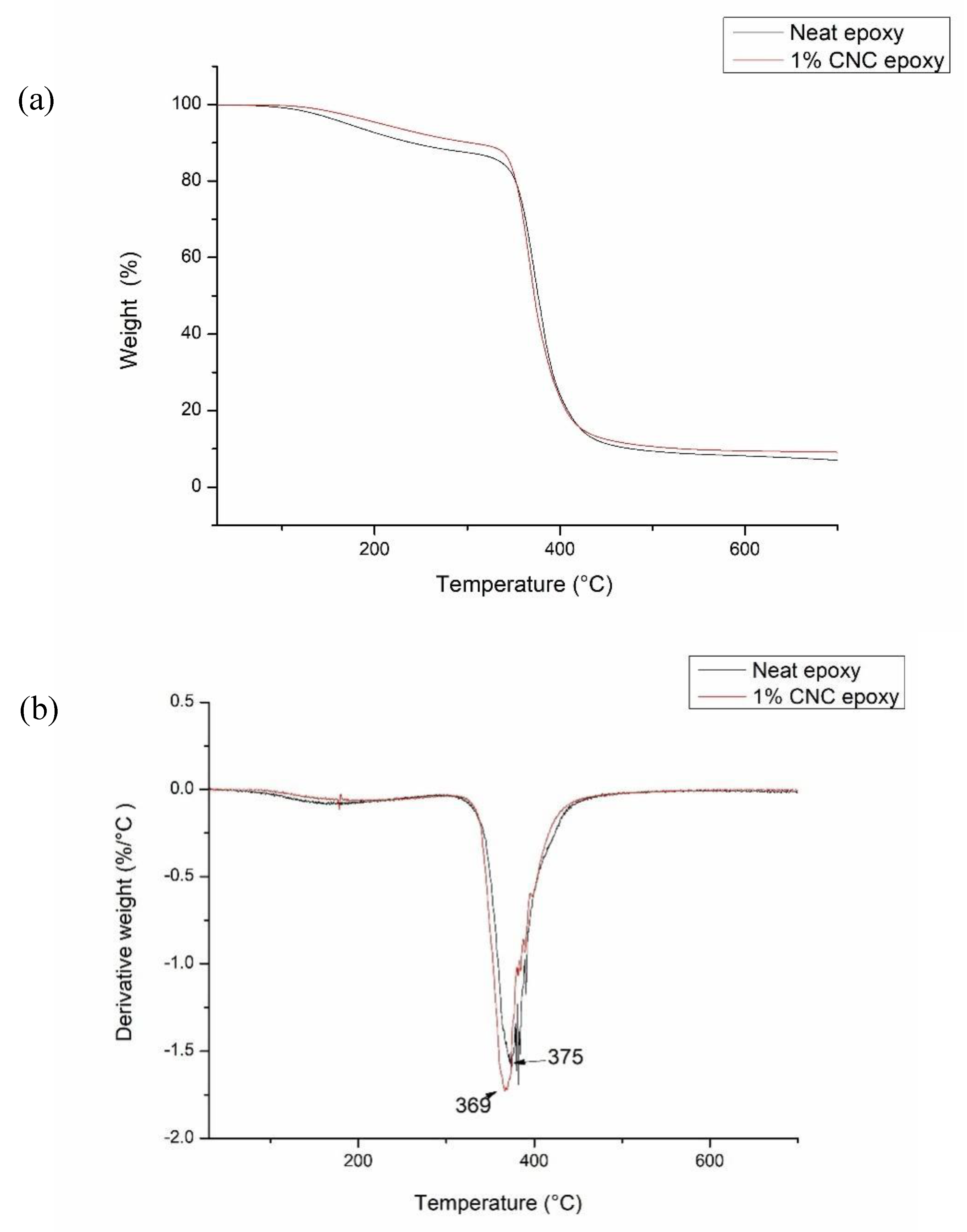
Figure 5.
The properties after cone calorimeter test: (a) total heat release (THR); (b) heat release rate (HRR); (c) total smoke production (TSP) of neat epoxy, 0.5 wt% CNC/epoxy and 1.0 wt% CNC/epoxy.
Figure 5.
The properties after cone calorimeter test: (a) total heat release (THR); (b) heat release rate (HRR); (c) total smoke production (TSP) of neat epoxy, 0.5 wt% CNC/epoxy and 1.0 wt% CNC/epoxy.
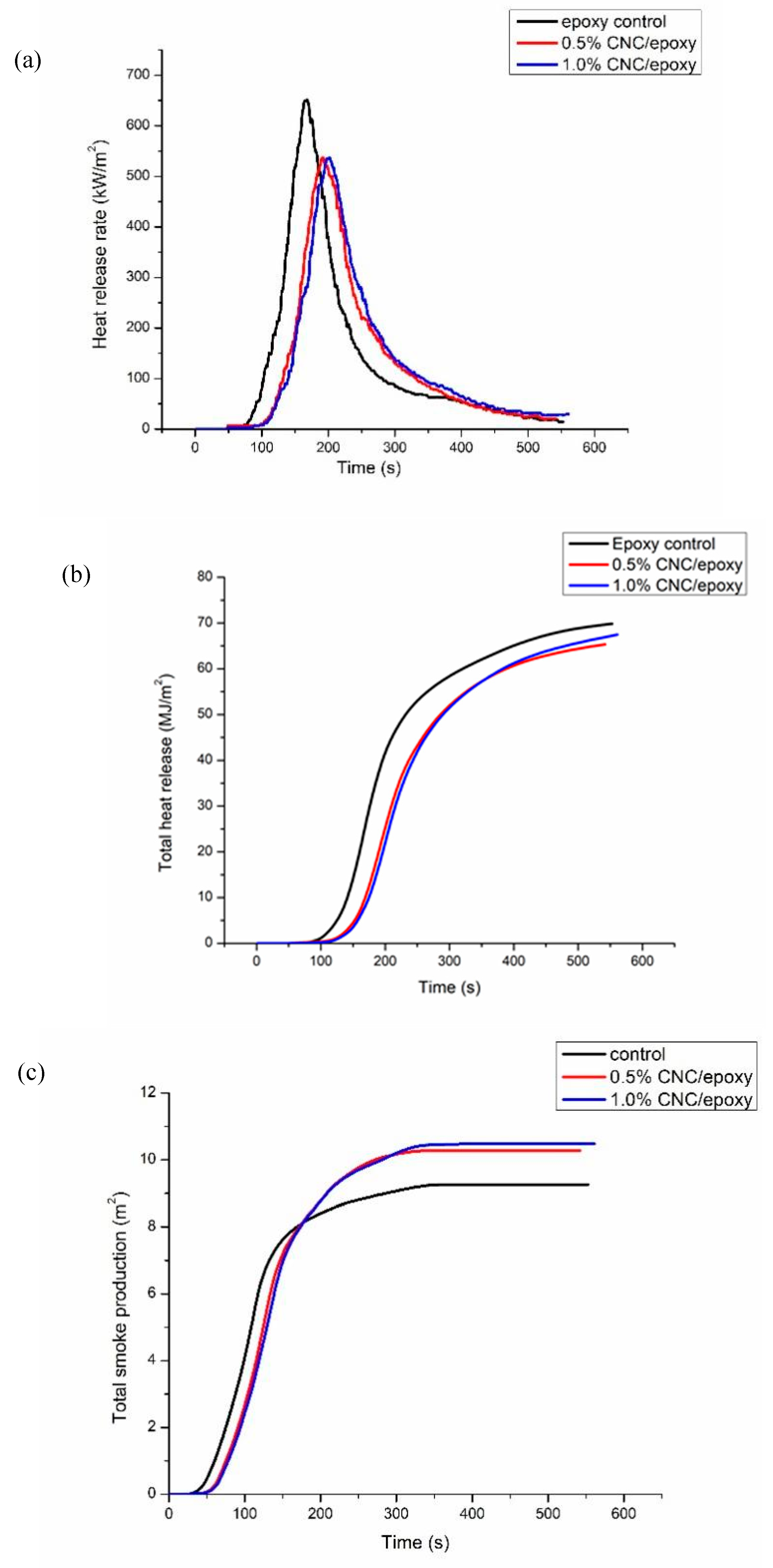
Figure 6.
Morphology of samples and char residues from cone calorimetry for: (a) epoxy; (b) epoxy after cone calorimetry test; (c) 0.5% CNC/epoxy; (d) 0.5% CNC/epoxy after cone calorimetry test; (e) 1.0% CNC/epoxy; (f) 1.0% CNC/epoxy after cone calorimetry test.
Figure 6.
Morphology of samples and char residues from cone calorimetry for: (a) epoxy; (b) epoxy after cone calorimetry test; (c) 0.5% CNC/epoxy; (d) 0.5% CNC/epoxy after cone calorimetry test; (e) 1.0% CNC/epoxy; (f) 1.0% CNC/epoxy after cone calorimetry test.
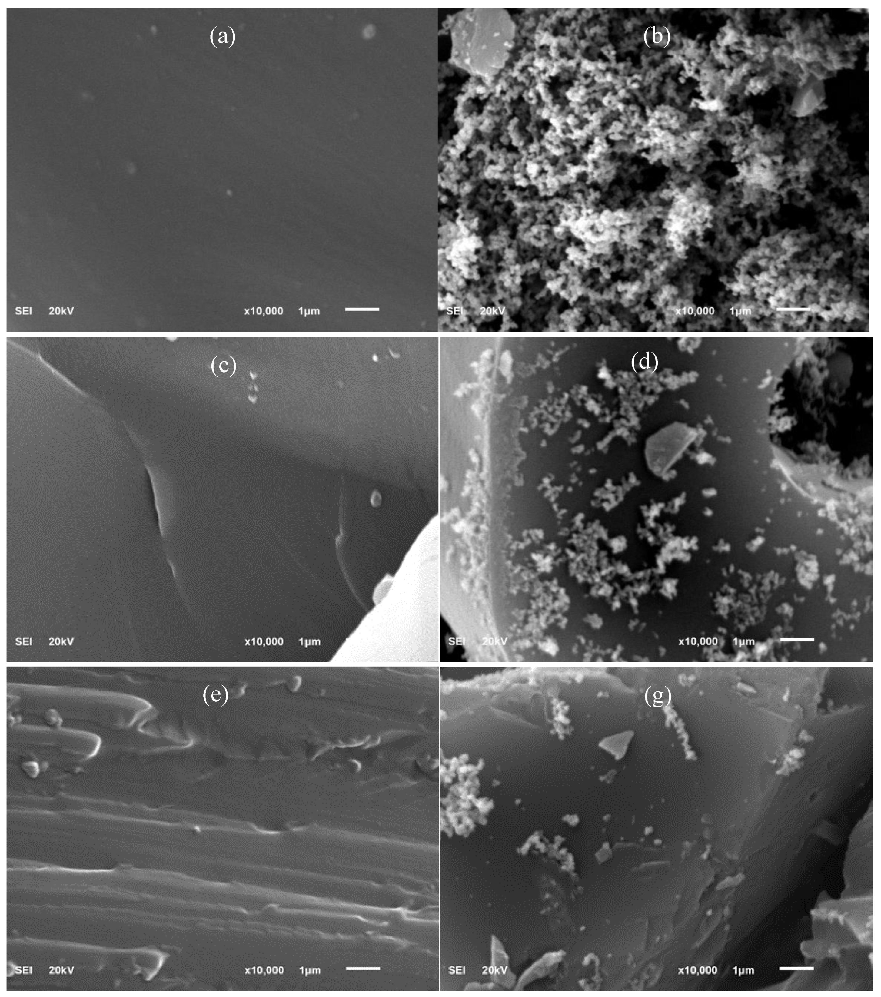
Figure 7.
Analysis on chemical composition of Epoxy and CNC/epoxy composites at different percentages by FTIR analysis before and after cone calorimetry test.
Figure 7.
Analysis on chemical composition of Epoxy and CNC/epoxy composites at different percentages by FTIR analysis before and after cone calorimetry test.
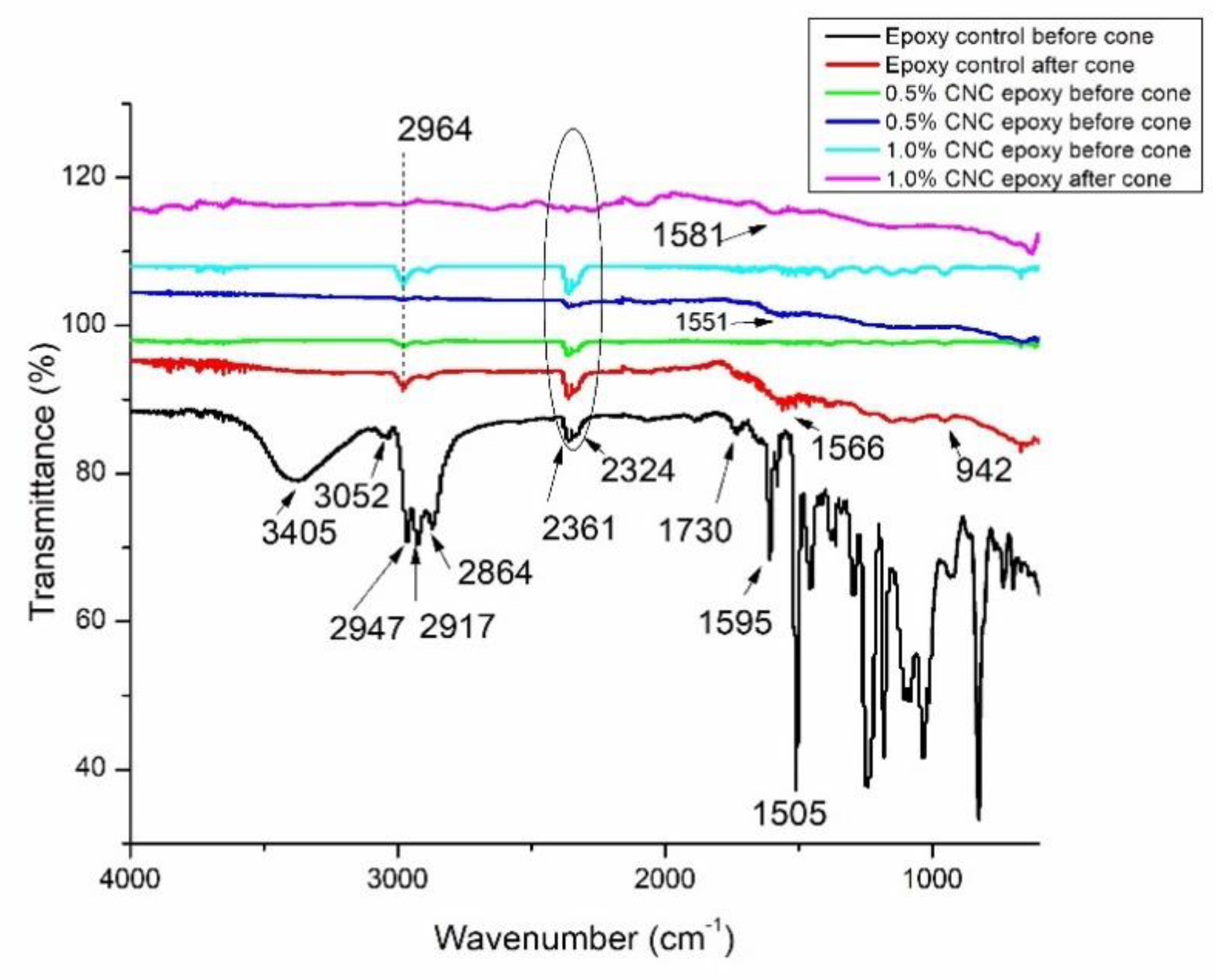

Table 1.
Data obtained from TGA thermogram.
| Type of samples | Onset degradation temperature, T0 (℃) | Maximum decomposition temperature, Tmax (℃) a |
| Neat epoxy | 314 | 375 |
| 1 wt% CNC-epoxy | 329 | 369 |
a from derivative thermogravimetric (DTG) curve obtained from TGA thermogram.
Table 2.
Cone calorimeter data of epoxy and epoxy composites.
| Sample | TTI (s) | pHRR(kW/m2) | THR(MJm-2) | TSP(m2) |
| Neat epoxy | 13 | 651.61 | 69.16 | 9.2 |
| 0.5% CNC/ epoxy | 17 | 537.56 | 63.98 | 10.3 |
| 1.0% CNC/ epoxy | 20 | 537.02 | 67.09 | 10.5 |
Note: TTI = time to ignition, pHRR = peak heat release rate, THR = total heat release, TSP = total smoke production.
Disclaimer/Publisher’s Note: The statements, opinions and data contained in all publications are solely those of the individual author(s) and contributor(s) and not of MDPI and/or the editor(s). MDPI and/or the editor(s) disclaim responsibility for any injury to people or property resulting from any ideas, methods, instructions or products referred to in the content. |
© 2025 by the authors. Licensee MDPI, Basel, Switzerland. This article is an open access article distributed under the terms and conditions of the Creative Commons Attribution (CC BY) license (http://creativecommons.org/licenses/by/4.0/).
Copyright: This open access article is published under a Creative Commons CC BY 4.0 license, which permit the free download, distribution, and reuse, provided that the author and preprint are cited in any reuse.


