Submitted:
21 July 2025
Posted:
23 July 2025
You are already at the latest version
Abstract
Accurate measurements of Earth gravity and its variations with time are crucial not only for fundamental research on gravitation in physics, but also for other scientific areas including Earth sciences and geophysics, as well for various applications such as geodesy, resource exploration, climate monitoring and navigation. Current test mass-based gravimeters are inherently sensitive to vibrations and inertia accelerations, which limits their sensitivity and accuracy in moving platform applications. Here we report an optical fibre sensing system designed for measuring gravity by exploring a recently demonstrated gravito-optic effect. Initial test results show photonics-based solid-state gravimeters with fast data sampling rates but without any moving parts in the systems could be feasible and novel gravity measurement technologies could be developed for moving platform continuous gravimetry, particularly for airborne gravity mapping and underwater navigation applications.
Keywords:
photonic sensing
; gravimetry
Introduction
The force of gravity on Earth is primarily governed by Newton's law of universal gravitation. However, the gravitational acceleration experienced by an object on the Earth surface is not uniform, but varies due to several factors, including changes in topography, subsurface geology, and the Earth’s rotation and shape. Accurate measurements of Earth gravity and its variations with time at a particular location are critically important and necessary not only for fundamental research on gravitation, Earth sciences and geophysics, but also for various applications such as geodesy, resource exploration, climate monitoring and navigation [1]. In order to measure and model the Earth's gravitational field, a field called gravimetry has been established and various kinds of methodologies and techniques have been developed for different applications [2-8].
Gravimeters, the instruments used to measure gravitational acceleration, can be classified into two categories, the absolute gravimeters and relative gravimeters. Absolute gravimeters measure the value of gravitational acceleration directly. The operational principle of an absolute gravimeter is quite simple and straightforward, that is, dropping a test mass in free-fall motion passing a known distance in a vacuum chamber and measuring the time used, so the free-fall acceleration can be calculated. Normally laser interferometers are used to precisely track the motion of test masses in the absolute gravimeters [9]. Recent advancements in the free-fall absolute gravimeters involve the use of cold atom interferometry. In this type of quantum gravimeter, cold atoms, such as Rb, are prepared in an ultrahigh vacuum chamber to be used as the test mass [10-16]. When the cold atoms are released in a free-fall manner, they undergo three stimulated Raman transitions, which separate, redirect, and recombine the atomic wave function, resulting in an atomic interferometer. The total phase shift between the two paths of the atomic interferometer depends on the local gravitational acceleration and scales with the square of the time interval between two consecutive Raman pulses. For the free-fall absolute gravimeters, an accuracy of a few μGals (1 μGal = 10⁻⁸ m s⁻²) can be achieved under well controlled laboratory conditions. Absolute gravimeters are normally more accurate but typically more bulky, complex and expensive than relative gravimeters as described below. Therefore, they can be utilised for establishing gravity reference points, calibrating relative gravimeters, and geophysical monitoring where high precision is critical.
The second class of gravimeters are relative gravimeters, which measure the difference in gravitational acceleration between two or more points on the Earth's surface. A typical relative gravimeter is the spring-based gravity measuring instrument in which a spring is utilised to support a mass and to measure displacement [17]. Another type of relative gravimeters is the superconducting gravimeters, where superconducting spheres are levitated in magnetic fields [18]. Superconducting gravimeters are extremely sensitive and can be used for long-term monitoring. The rapid development of the micro-electromechanical systems (MEMS) has provided unique opportunities for developing compact and low-cost relative gravimeters [19-21]. Relative gravimeters are crucial tools in geophysics and engineering. Their ability to detect tiny gravity changes makes them invaluable for mapping underground features, monitoring geological activity, and supporting resource exploration. Although relative gravimeters have to be calibrated by using absolute gravimeters, their portability and precision make them the workhorses of field-based gravimetry.
Gravitational fields can also be measured and characterised by using gravity gradiometer, which measures spatial variations (gradients) in the gravitational field, specifically, how gravity changes over short distances [22]. Unlike standard gravimeters, which detect the magnitude of gravity at a point, gradiometers measure the rate of change of gravity across space. This makes them especially useful for detecting fine-scale geological structures and mass distributions underground or beneath the ocean floor.
The operational principle of the current gravimeters is measuring the gravitational acceleration generated by the Earth gravity, therefore, all of them inherently are sensitive to the vibrations of the operation environments. Although various kind of techniques have been implemented to mitigate the influence and impact of the vibrations, it is still a key problem in the measurement of gravity from moving platforms. On top of that, the inertial accelerations of the moving platforms also have to be separated from the gravitational accelerations. These are all accuracy limiting factors for airborne and ship-borne gravimetry. Another limitation of the current gravity measuring technologies is the sampling data rate is in a few Hz range, which is quite low for continuous gravity field mapping applications.
In this paper, we report a different gravity sensing method by exploring the recently demonstrated gravo-optic effect, in which, the local speed of light is a function of gravity [23]. Based on the gravito-optic effect, an experiment aiming for gravity sensing has been designed and carried out. The results show that photons instead of test masses could be utilised for gravity sensing applications. By comparing to the existing gravity measurement technologies, the photonic gravimeters are completely solid-state sensing systems without any moving parts, eliminating the direct impacts caused by the vibrations and the inertial accelerations of the moving platforms. Another unique feature of the potential photonic gravimeters is the sampling rate could go up to kilo even mega Hz.
Principle and Description of the Sensing System
In a previous study, we experimentally demonstrated that light could intact with the Earth gravitational field and consequently the speed of light would be affected by the Earth gravity [23]. In the experiments, we utilised ultrafast laser pulses to measure the travel time in an optical fibre spool with a total return length of 20 km at different heights above the ground level in order to obtain different Earth gravities. Even though multiple measures were implemented for isolating the Earth gravity from other environmental influences including changes of temperature, pressure and humidity, it is desirable to carry out further tests to verify the previously reported phenomena and results with more confidence that any possible non-gravity factors will be eliminated completely. To that end and also for gravity sensing purpose, we designed and built an alternate fibre-optic system in which two identical optical fibre spools were employed and arranged in a differential mode to overcome any possible common mode influences.
A diagram of the sensing system is shown in Fig.1. Two optical fibre spools (labelled as Fibre spool 1 and 2) with the same length of 10 km are arranged in the vertical direction with a spacing of 1 m between them. Laser pulses from a femtosecond fibre laser (FemtoFiber pro, from TOPTICA Photonics) first pass an optical isolator and every pulse is split into two by a 50/50 directional fibre coupler. The two output ports of the coupler are connected to the fibre spools. The laser pulses are reflected back by two in-fibre Faraday mirrors connected at the ends of the fibre spools. By this way, the actual travel length of the laser pulses is 20 km. The reflected laser pulses coming out of the directional coupler are connected to a chromatic dispersion compensator (DCMS-SM-C100%-020-LCP-05, from Yangtze Optical System Corp. Ltd, Wuhan, China) to compress the broaden laser pulses. The lengths of the fibre spools need to be matched precisely to ensure that the two adjacent pulses are reflections from a single input pulse. In this way, the time delay differences generated by the two fibre spools could be accurately measured. With this arrangement, the setup shown in Fig.1 is in fact configured as a gravity gradiometer and any changes in gravities experienced by the fibre spools would affect the time delay between the two adjacent pulses. Hence by measuring the time delays, we would obtain information of the relative changes of gravity that the fibre spools are experiencing.
Figure 1.
A schematic diagram of the optical fibre sensing system. The setup is configured as a gravity gradiometer based on the dependence of the speed of lights in two optical fibre spools under different gravitational fields.
Figure 1.
A schematic diagram of the optical fibre sensing system. The setup is configured as a gravity gradiometer based on the dependence of the speed of lights in two optical fibre spools under different gravitational fields.
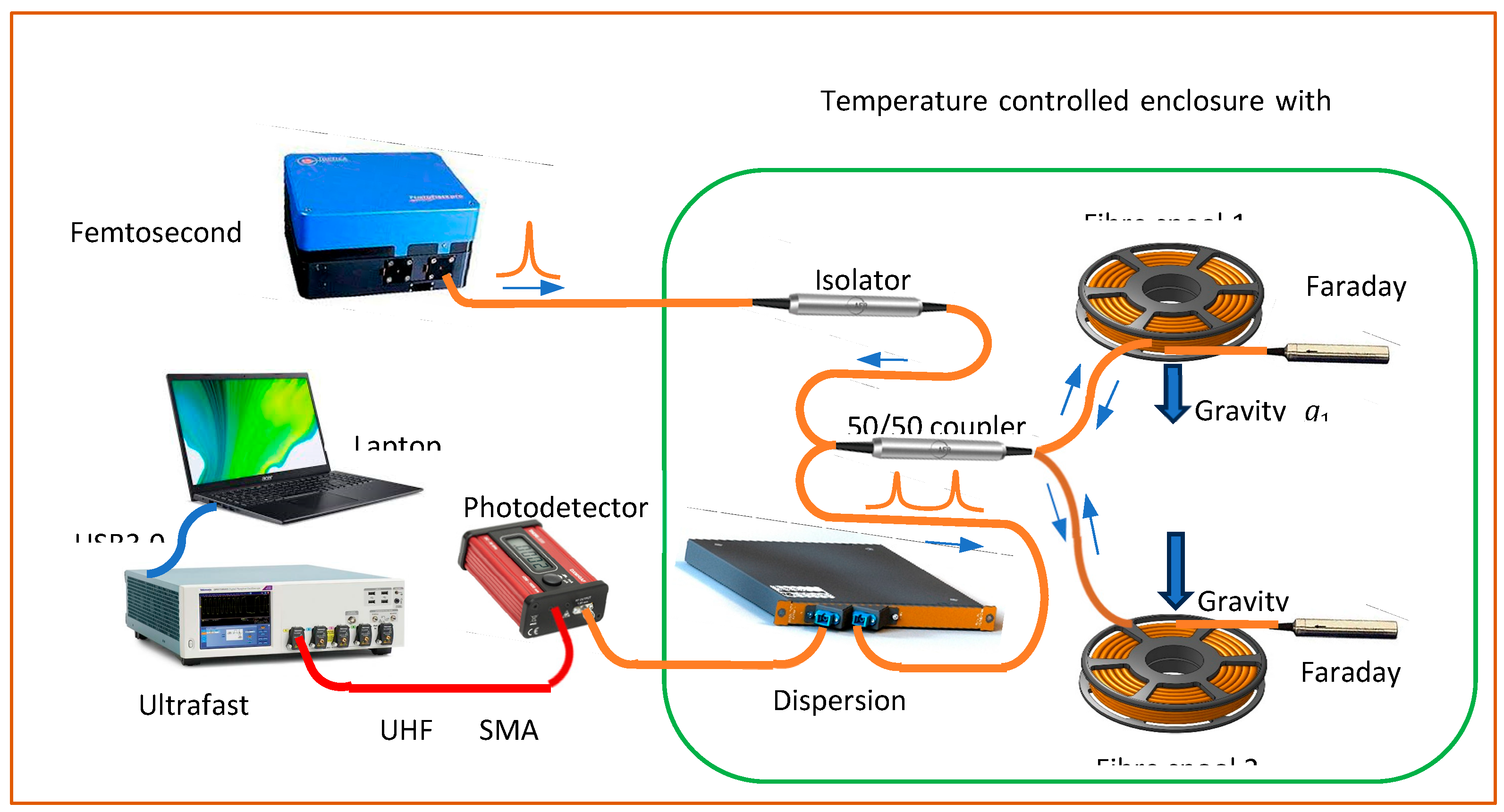
The compressed optical pulses are detected by an ultrafast photodetector (DXM30BF, from ThorLabs) with a bandwidth larger than 30 GHz in the 750 nm-1650 nm wavelength range. After converting the laser pulses to electrical signals, a real-time digital oscilloscope (DPO 73308 SX, from Tektronix) with a signal bandwidth of 33 GHz and a sampling rate of 100 GSa/s is used to measure the time delays.
In order to achieve precise temperature control for the optical system, three copper enclosures, two for the fibre spools (called ENC1 and 2 for fibre spool 1 and 2 respectively) and one for other optical components (called ENC3), were constructed. Silicone rubber heating wires are unfirmly wound around the enclosures as the heating elements and 2 cm thick insulating foams are glued to the outsides of the enclosures for thermal insulation and sealing purpose. The copper enclosures are also electrically grounded to shield any possible EM interference. PT100 temperature sensors are attached to the copper enclosures and connected to three independent digital temperature controllers. The fibre patch cords linking ENC3 to ENC1 and ENC2 are inserted in temperature-controlled pipes which are parts of the temperature control system of ENC3. All of the passive components of the optical system are arranged in a plastic box to further isolate them from the environment.
Experiments and Results
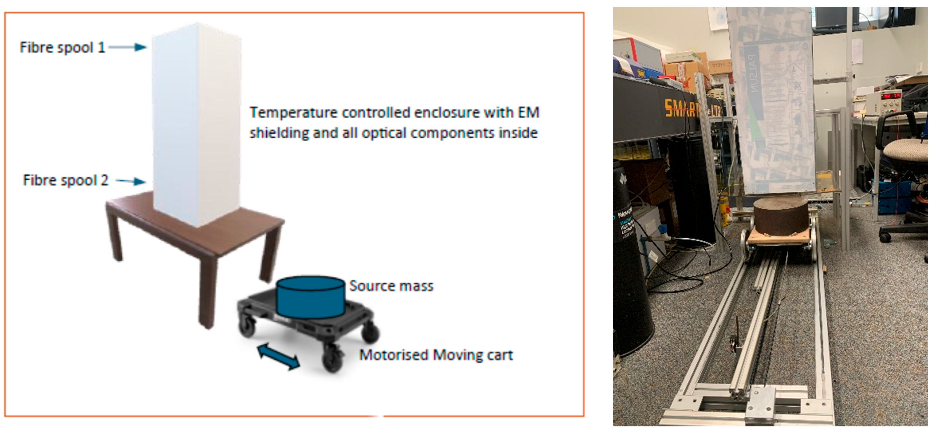
For testing the gravity sensing system, we need to generate gravity gradients in a controllable way. To that end, we designed a motorised moving mass set-up, as shown in Fig.2. With this set-up, we could put a source mass directly underneath the fibre spool 1, or move it away from the fibre spool by a distance of 1.5 m. When the source mass is moved in, it would generate a stronger gravitational force on fibre spool 1 than that on fibre spool 2, thus a gravity gradient could be generated to the sensing system. The source mass can be moved in and out of the sensing system periodically and the period can be accurately set by from a controller. A source mass of 72 kg was used for tests reported here.
Figure 2.
A schematic diagram and photograph of the experimental setup.
The tests were carried out in a laboratory, within it the temperature and pressure were kept constant during the experiments. The room temperature in the laboratory was set at 23 °C and the temperatures of all three enclosures were set at 30.0 °C.
We operated the FemtoFiber pro at 80 MHz repetition rate for the 1560 nm fundamental wavelength. The average power of the seed laser pulses from the FC/APC fibre output port was 1 mW and the pulse width (after a 2 m long fibre patch cord) was measured as 550 fs by using an auto-correlator.
Shown in Fig. 3 are the recorded pulse waveforms by using the photodetector and the digital oscilloscope with a sampling rate of 100 Gs/s. The leading pulse in Fig.3(a) was from fibre spool 1 and the second pulse was from fibre spool 2. The time delay between the two pulses was what we needed to measure in the experiments, and it was done by utilising the build-in functions of the digital oscilloscope. Fig.3(b) is a zoom-in waveform of the leading pulse from which a pulse width of around 90 ps was measured. The difference between the initial input pulse width (550 fs) and that directly measured by using the photodetector and the digital oscilloscope should be determined by the uncompensated dispersion, the bandwidths and time responses of the measurement instruments.
Figure 3.
Recorded pulse signals by using Tektronix DPO 73308 SX digital oscilloscope.

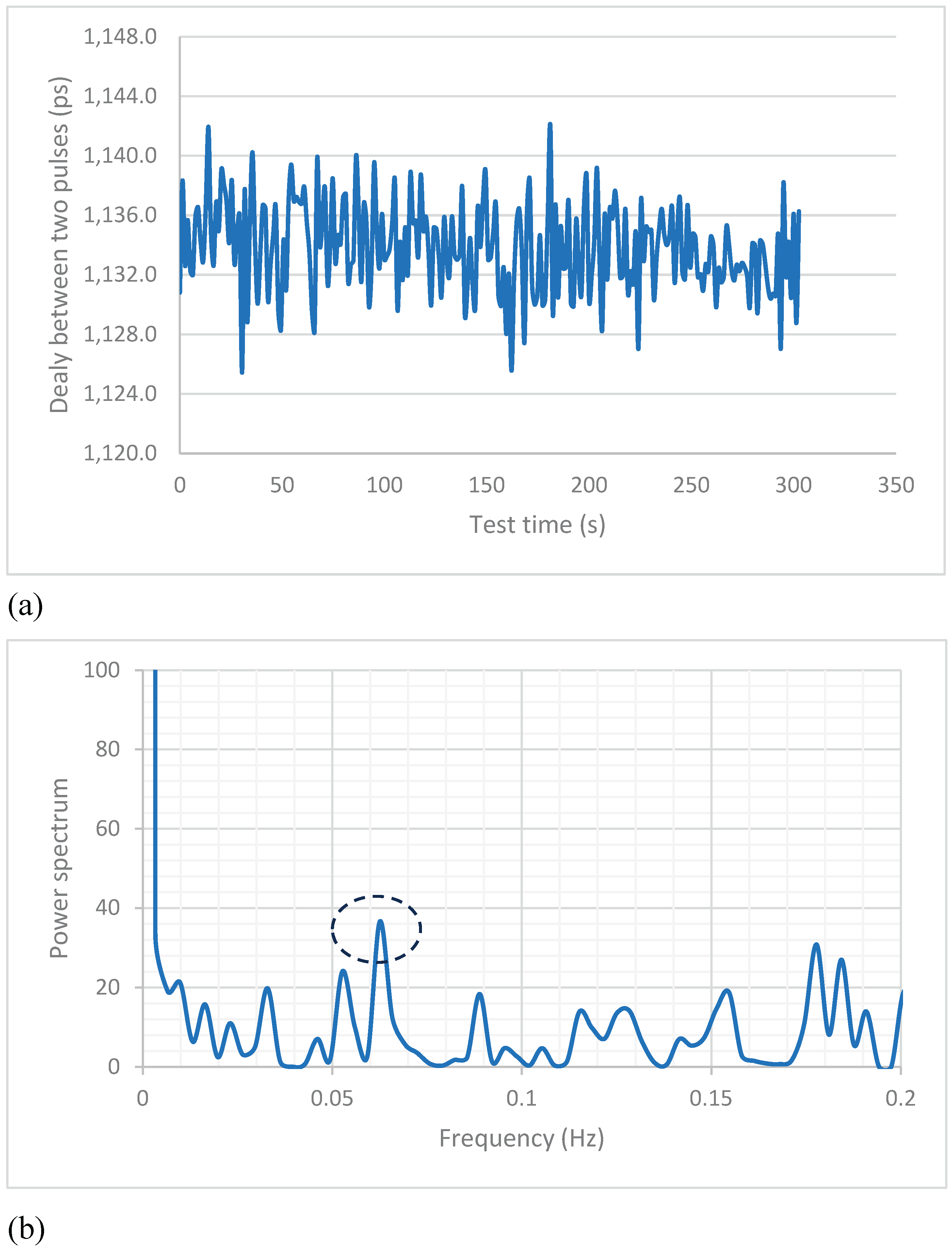
In the experiments, we set the period of the moving mass at 16.5 s, which is equivalent to a changing rate of 0.061 Hz in the gravity field. Displayed in Fig.4(a) are the measured time delays between two reflected laser pulses as a function of test time when the source mass was in and out of the sensing system with a preset period of 16.5 s. It can be seen that the time delays fluctuate in a few picoseconds range and it is unclear if the periodical motion of the source mass producing any influence on the recorded data. As a further analysis, we performed FFT of the recorded time delay data and the power spectra are presented in Fig.4(b). From the FFT spectra, we can see that a peak (circled in the figure) appears at a frequency of 0.064 Hz. This clearly demonstrates that the designed sensing system response to the periodical gravitational field changes introduced by the 72 kg moving mass. To further confirm this result, we repeated the tests for multiple times and obtained an average frequency of 0.062 Hz, which matches the moving frequency of the source mass.
Figure 4.
Measured time delays between two reflected laser pulses as a function of time when the source mass was moving in and out of the sensing system with a period of 16.5 s (a), and FFT of the recorded time delay data (b).
Figure 4.
Measured time delays between two reflected laser pulses as a function of time when the source mass was moving in and out of the sensing system with a period of 16.5 s (a), and FFT of the recorded time delay data (b).
Discussion and Conclusion
We designed a gravity sensing system by exploring a recently demonstrated gravito-optic effect and tested it by using a moving source mass method. Since the gravity sensing experiments were carried out in a laboratory with well controlled conditions, including constant room temperature, air pressure and humidity, we are confident that any no-gravitational factors have been eliminated and the detected the time delays are the responses to the gravity changes caused by the periodical motion of the source mass. The experimental results, even though in a qualitative manner, not only confirm the results reported previously [23], but also show the potential for developing photonic systems for gravity measurements. Further research aiming for quantitative measurements is currently under way.
As demonstrated previously, the observed dependence of the light speed on the gravity is extremely small [23]. For a typical system like the one used in this study, the time delay changes would be in picosecond range. Therefore, the delay measurement accuracy should be in sub-picosecond, which is what the current set-up can achieve. For obtaining better accuracy, a number of improvements need to be considered. First, better dispersion management of the fibre system and input pulse shapes should be implemented for compressing the pulse width of the reflected signal. Secondly, photodetectors with broader bandwidths or faster time responses should be utilised.
All of the existing gravimeters (both absolute and relative) are using a test mass or proof mass to perform gravity measurements; therefore, any vibrations or inertial accelerations would affect the operations of the gravimeters. The photonics-based gravimeters or gravity gradiometers will overcome this drawback since photons instead test masses are utilised for the sensing purpose. Another important feature is that data sampling rate could go up to kilo or even mega Hertz since one measurement can be done for any single laser pulse if the signal recording and processing electronics is fast enough. Solid-state gravimeters with fast data sampling rates but without any moving parts in the systems would be desirable for continuous onboard gravimetry, particularly for airborne gravity mapping and underwater navigation applications.
Data Availability Statement
Data sets generated during the current study are available from the corresponding author on reasonable request.
Acknowledgements
The author would like to thank Roger Lewis, Anatoly Rosenfeld and Michael Lerch for their support and useful discussions. The technical support provided by Hayden Schippers and Angus Wu from VICOM AUSTRALIA is also acknowledged.
References
- Torge, W. Gravimetry, Walter De Gruyter, Berlin, Germany (1989).
- Marson, I. A Short Walk along the Gravimeters Path. INTERNATIONAL JOURNAL OF GEOPHYSICS 2012. [Google Scholar] [CrossRef]
- MARSON, I. & FALLER, J. G - THE ACCELERATION OF GRAVITY - ITS MEASUREMENT AND ITS IMPORTANCE. JOURNAL OF PHYSICS E-SCIENTIFIC INSTRUMENTS, 1986; 19, 22–32. [Google Scholar] [CrossRef]
- Fang, J.; et al. Classical and Atomic Gravimetry. REMOTE SENSING 2024, 16. [Google Scholar] [CrossRef]
- Carbone, D.; et al. The NEWTON-g Gravity Imager: Toward New Paradigms for Terrain Gravimetry. FRONTIERS IN EARTH SCIENCE 2020, 8. [Google Scholar] [CrossRef]
- Che, H.; et al. Ship-Borne Marine Absolute Gravimetry via Sensors Ultratight Fusion of an Atomic Gravimeter and a Classical Accelerometer. IEEE TRANSACTIONS ON INSTRUMENTATION AND MEASUREMENT 2025, 74. [Google Scholar] [CrossRef]
- Vovrosh, J. , Dragomir, A., Stray, B. & Boddice, D. Advances in Portable Atom Interferometry-Based Gravity Sensing. SENSORS 2023, 23. [Google Scholar] [CrossRef]
- Yin, P.; et al. Experiments with levitated force sensor challenge theories of dark energy. NATURE PHYSICS 2022, 18, 1181. [Google Scholar] [CrossRef]
- Hammond, J. and Faller, J. 12.5 - Laser-interferometer system for the determination of the acceleration of gravity, IEEE Journal of Quantum Electronics, vol. 3, no. 11, pp. 1967, 67, 597–602. [Google Scholar] [CrossRef]
- Peters, A. , Chung, K. & Chu, S. High-precision gravity measurements using atom interferometry. METROLOGIA 2001, 38, 25–61. [Google Scholar] [CrossRef]
- Bidel, Y.; et al. Absolute marine gravimetry with matter-wave interferometry. NATURE COMMUNICATIONS 2018, 9. [Google Scholar] [CrossRef] [PubMed]
- Geiger, R. , Landragin, A., Merlet, S. & Dos Santos, F. High-accuracy inertial measurements with cold-atom sensors. AVS QUANTUM SCIENCE 2020, 2. [Google Scholar] [CrossRef]
- Greve, G. , Luo, C., Wu, B. & Thompson, J. Entanglement-enhanced matter-wave interferometry in a high-finesse cavity. NATURE 2022, 610, 472. [Google Scholar] [CrossRef] [PubMed]
- Jaffe, M.; et al. Testing sub-gravitational forces on atoms from a miniature in-vacuum source mass. NATURE PHYSICS 2017, 13, 938. [Google Scholar] [CrossRef]
- Stray, B.; et al. Quantum sensing for gravity cartography. NATURE 2022, 602, 590. [Google Scholar] [CrossRef] [PubMed]
- Panda, C.; et al. Measuring gravitational attraction with a lattice atom interferometer. NATURE 2024, 631. [Google Scholar] [CrossRef]
- Lucien J., B. LaCoste; A New Type Long Period Vertical Seismograph. Physics 1934, 5, 178–180. [Google Scholar] [CrossRef]
- Neumeyer, J. Superconducting Gravimetry. In: Xu, G. (eds) Sciences of Geodesy - I. Springer, Berlin, Heidelberg (2010). [CrossRef]
- Middlemiss, R.; et al. Measurement of the Earth tides with a MEMS gravimeter. NATURE 2016, 531, 614. [Google Scholar] [CrossRef] [PubMed]
- D'Alessandro, A. , Scudero, S. & Vitale, G. A Review of the Capacitive MEMS for Seismology. SENSORS 2019, 19. [Google Scholar] [CrossRef]
- Wang, C.; et al. Micromachined Accelerometers with Sub-μg/√Hz Noise Floor: A Review. SENSORS 2020, 20. [Google Scholar] [CrossRef]
- Jekeli, C. Gravity, Gradiometry. In: Gupta, H.K. (eds) Encyclopedia of Solid Earth Geophysics. Encyclopedia of Earth Sciences Series. Springer, Dordrecht (2011). [CrossRef]
- Li, E. Experimental Demonstration of Gravitational Impact on the Speed of Light. Ann Math Phys. 2025;8(4):096-101. [CrossRef]
Disclaimer/Publisher’s Note: The statements, opinions and data contained in all publications are solely those of the individual author(s) and contributor(s) and not of MDPI and/or the editor(s). MDPI and/or the editor(s) disclaim responsibility for any injury to people or property resulting from any ideas, methods, instructions or products referred to in the content. |
© 2025 by the authors. Licensee MDPI, Basel, Switzerland. This article is an open access article distributed under the terms and conditions of the Creative Commons Attribution (CC BY) license (http://creativecommons.org/licenses/by/4.0/).
Copyright: This open access article is published under a Creative Commons CC BY 4.0 license, which permit the free download, distribution, and reuse, provided that the author and preprint are cited in any reuse.


