
Submitted:
17 July 2025
Posted:
18 July 2025
You are already at the latest version
Abstract
Aluminium is widely used in many industries like automotive, aerospace and construction because of its low weight, good mechanical strength and resistance to corrosion. This resistance comes mainly from a passive oxide layer that forms on its surface. However, when aluminium is exposed to harsh environments, especially those containing chloride ions in marine environments, this layer can break down and lead to localized corrosion, such as pitting. This study examined aluminum profiles at different processing stages, including homogenization and aging, anodizing and pre-anodizing followed by The corrosion behavior of the samples was studied using two electrochemical methods. Potentiodynamic polarization was used to measure corrosion rate and current density, while Electrochemical Impedance Spectroscopy (EIS) helped to understand how the protective layers behave and how corrosion progresses. The tests were carried out in a 3.5% NaCl solution at room temperature. The EIS results were analyzed using equivalent circuit models to better understand the electrochemical processes. Overall, the study shows how surface treatment affects corrosion resistance and highlights the advantages of EIS in studying corrosion behavior in a more reliable and repeatable way.
Keywords:
aluminum profile
; EN AW 6060
; potentiodynamic polarization
; electrochemical impedance spectroscopy (EIS)
; microstructure
1. Introduction
Aluminum and its alloys are widely used across industries such as aerospace, automotive and construction, due to their favorable properties, including low density, high mechanical strength, excellent thermal and electrical conductivity and ease of manufacturing and recycling [1]. In architectural applications and sectors like automotive, aerospace and construction aluminum profiles combine attractive aesthetics, mechanical robustness and corrosion resistance [2]. However, they can be susceptible to certain types of localized corrosion, including filiform, pitting, crevice and intergranular corrosion. To address this issue, various accelerated laboratory corrosion tests have been conducted; however, they do not provide a solution to predicting the corrosion tendency combined with the selected surface treatment system [3]. The increasing use of recycled aluminum in architectural constructions is a best practice because it significantly reduces energy costs, carbon emissions and retains its original properties, such as strength and corrosion resistance, and is infinitely recyclable without degradation. But on the other hand, it can create potential problems in the corrosion resistance of the parent material. A poorly executed homogenization process in secondary aluminium billet production can significantly compromise corrosion resistance, leading to performance issues in downstream applications.
More specifically, the role of intermetallic compounds, the uneven grain structure and the chemical segregation that are created during casting and continue to exist during the thermomechanical processes that follow, is under investigation as they may constitute preferential ascending routes leading to localized corrosion and a reduction in the corrosion resistance of structures [4].
The production of aluminum profiles is a process that requires precision and expertise at every stage, from the selection of the appropriate alloy to the final surface treatment. The quality of the final product depends on the correct implementation of each step and understanding the scientific principles governing production is crucial to optimizing the process and achieving high-quality profiles.
The choice of aluminum alloy is the first and fundamental step. Each alloy has unique properties that make it suitable for specific applications. The 6000 (Al-Mg-Si) series, for example, offers excellent corrosion resistance and extrudability, making it ideal for automotive and architectural construction applications [2]. Other alloys, such as the 7000 (Al-Zn) series, offer high strength, suitable for aerospace applications [5]. The choice of alloy directly affects the mechanical properties, corrosion resistance and processability of the final product.
A major benefit of aluminum is its inherent corrosion resistance, which is due to the spontaneous formation of a thin and stable oxide layer that protects the surface from further degradation. Anodizing is a widely used electrochemical process that creates a protective, decorative, and durable oxide layer on the surface of the aluminum profiles. During anodizing, the aluminum part serves as the anode in an electrolytic cell, forming a controlled, nanoscale porous oxide film. The properties of the film can be adjusted by critical parameters control of voltage, current density, electrolyte concentration, temperature, and anodizing time [6,7]. Among various anodizing techniques, sulfuric acid anodizing is preferred for decorative finishes and moderate corrosion protection. The 6xxx series alloys, particularly 6060, are well-suited to this process due to their favorable anodizing response, good formability and balanced mechanical properties [8].
Despite surface treatments, aluminum in aggressive conditions, especially in seawater, can still lose its protective oxide layer, causing localized corrosion such as pitting. This can quickly damage the structural integrity [9,10,11,12,13]. To better understand aluminum corrosion mechanisms and improve durability, numerous experimental methods have been developed. Traditional techniques such as weight loss measurement provide simple estimates of material degradation but are time-consuming and offer limited insight into corrosion mechanisms. Hydrogen evolution methods quantify corrosion rates based on gas generation but can be influenced by external factors such as temperature and pressure, limiting reliability [14,15,16]. Corrosion tests like acetic acid salt spray (AASS, ISO 9227) and Filiform corrosion test (FFC, ISO 4623-2) are commonly used for assessing the corrosion resistance of decorative coatings but often fails to replicate complex real-world conditions, resulting in variable and sometimes non-representative results [17,18,19,20,21]. Electrochemical Noise Analysis can monitor spontaneous fluctuations related to corrosion but presents challenges in data interpretation and usually requires supplementary methods [22,23,24,25,26].
To overcome these problems, Electrochemical Impedance Spectroscopy (EIS) is used as a strong, non-damaging tool that can carefully and repeatedly monitor corrosion in real time. EIS enables the detection of minor defects before they become visible under electron microscopy and allows continuous monitoring of the same samples. By measuring impedance over a range of frequencies, EIS provides detailed information about charge transfer, film stability, diffusion and double-layer behavior [27,28,29,30,31]. Also, modeling corrosion with equivalent electrical circuits from EIS data helps explain corrosion processes, evaluate coating performance, and monitor changes over time without damaging the sample. This study investigates the corrosion behavior of EN AW 6060 aluminum alloy samples subjected to various surface treatments. Electrochemical corrosion techniques, including potentiodynamic polarization and EIS were employed, while scanning electron microscopy (SEM) to analyze the morphology of the treated surfaces.
2. Materials and Methods
2.1. Materials and Coating Production
In this study, four EN AW 6060 aluminum alloy profiles samples were examined. One untreated sample was used as a reference after it was homogenized and aged (initial), while the other three were subjected to different surface treatments, such as clear anodizing, black anodizing and one pre-anodized coated sample, to assess their corrosion resistance and aesthetic properties. For the clear and the black anodized sample, the used process was sulfuric acid anodizing according to Qualanod and DIN 17611 specifications. The production steps are: alkaline degreasing, alkaline etching, desmutting, anodizing, electro coloring and cold sealing. Careful control of these parameters ensures a uniform and durable oxide layer suitable for a variety of applications. This process resulted in an approximately thickness of 17 μm oxide layer, composed of hexagonal columnar cells with nanometric pores [31,32,33,34].
The third sample was anodic pretreated and coated with architectural polyester powder. Pre-anodizing is a process that forms a protective oxide layer of 5-8 μm on the profiles before powder coating. This treatment improves corrosion resistance of the aluminium profiles. This combined surface treatment sample was produced according to Qualicoat specifications. Overall, these three treatments, like clear anodizing, black anodizing, and pre-anodizing combined with powder coating, provide a complete way to compare different surface modification methods on EN AW 6060 aluminum alloys.
2.2. Experimental Procedure
Corrosion characterization of the aluminium samples was conducted using potentiodynamic polarization and electrochemical impedance spectroscopy (EIS). Potentiodynamic polarization was used to determine the corrosion potential (Ecorr), corrosion current density (Icorr) and corrosion rate for each sample. EIS measurements were performed to investigate the electrochemical behavior over a frequency range, typically from 100 kHz to 100 mHz. The impedance data were analyzed using electrical circuit models to understand how different layers, like oxide films and coatings, contribute to corrosion protection and to quantify parameters such as pore resistance, coating capacitance and diffusion effects.
All electrochemical tests were carried out in a 3.5 wt.% NaCl aqueous solution at room temperature (25 °C) using a Gamry potentiostat/galvanostat system. A standard three-electrode setup was used, with the aluminium sample as the working electrode, a platinum rod as the counter electrode and a saturated calomel electrode (SCE) as the reference. The microstructure of the aluminum matrix as well as the coatings formed through different surface treatments was analyzed using Scanning Electron Microscopy (SEM).
3. Results and Discussion
3.1. Surface Morphology
Figure 1a presents SEM micrographs of the aluminum matrix, clearly revealing grain boundaries and possible inclusions. These microstructural features reflect the complex internal structure of the alloy. The prominent lines denote the interfaces between individual grains, while dispersed particles may correspond to secondary phases or impurities. In 6xxx series aluminum alloys, magnesium and silicon are the primary alloying elements, with iron, manganese and chromium typically present as trace elements or impurities. During solidification and subsequent processing, these elements form intermetallic compounds that play a critical role in determining the alloy’s mechanical performance and corrosion behavior. Common Fe-rich phases include β-Al9Fe2Si2 (also known as β-Al5FeSi) and α-Al12Fe3Si. In the presence of Mn or Cr, these atoms can replace Fe within the crystal structure, promoting the formation of intermetallic phases such as α-Al12(FeMn)3Si or α-Al12(FeCr)3Si [35].
Figures 1 (b, c) depict SEM images of the anodized layers, which exhibit a fibrous morphology that develops along the growth direction of the layer. The fibers within the oxide are aligned parallel to one another, forming gaps between them. The porosity of these oxide layers plays a crucial role in defining their function. The type, size and shape of the pores depend on factors such as the substrate’s structure, the etching conditions of the aluminum alloy surface, the electrolyte type and the parameters of the anodizing process [36]. The black anodized layer is visibly thicker (~18 μm) than the clear natural one (~17 μm), likely due to different anodizing parameters. The anodized layer is well-adhered to the substrate, with no evidence of interfacial defects or delamination. The sample that was both anodized and powder coated shows a well-formed multilayer structure (Figure 1d). However, in the magnified surface image of the anodized samples, some voids and discontinuities are observed within the anodic oxide layer. These features are indicative of poor sealing, which can reduce the long-term effectiveness of anodizing by allowing chloride ions to penetrate through the porous structure. Despite this limitation, the presence of the additional powder coating layer significantly minimizes this risk. The powder coating acts as a supplementary barrier, filling surface defects and sealing the underlying oxide layer, thereby enhancing the overall corrosion resistance of the system.
3.2. Electrochemical Characterization
Figure 2 shows the potentiodynamic polarization curves of the aluminium samples to study the influence of different surface treatments on corrosion behavior in 3.5% NaCl solution at 25 °C. The anodized samples show significantly lower current densities values compared to the initial (uncoated) samples, in which a clear tendency for pitting corrosion is observed. The anodized and powder coated sample exhibits the lowest corrosion current density among all tested samples. This confirms the synergistic protective effect of combining anodization and electrostatic coating, creating a dual barrier against corrosion. A tendency for pitting corrosion, indicated by the pitting potential (Epit), was also observed in both natural and black anodized samples. This means that although anodizing improves general corrosion resistance, it does not fully protect against localized corrosion. Small defects or pores in the oxide layer may allow pitting to start under certain conditions. Additionally, metastable pits, reflected as small current fluctuations, typically occur at voltages approaching the pitting potential (Epit) [37].
Figure 2.
Potentiodynamic polarization curves of aluminium samples with different surface treatments in sodium chloride solution.
Figure 2.
Potentiodynamic polarization curves of aluminium samples with different surface treatments in sodium chloride solution.
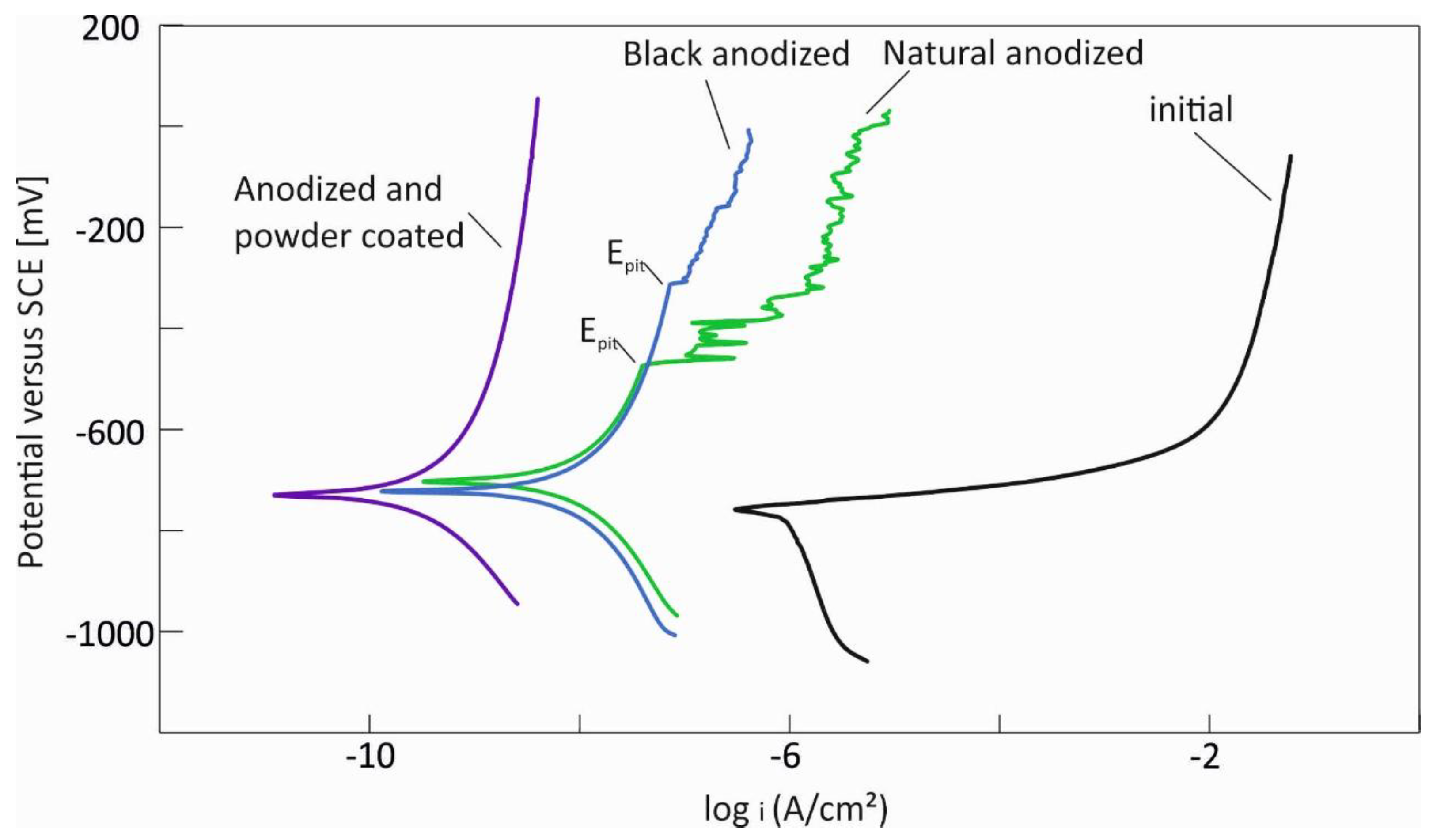
Table 1 shows the corrosion potential (Ecorr), corrosion current density (icorr), the anodic (βa) and cathodic (βc) Tafel slopes for aluminium samples with different surface treatments in sodium chloride solution. The corrosion current densities (Icorr) and corrosion rates decrease with the application of various surface treatments compared to the initial sample. The initial sample exhibits the highest Icorr value and a corresponding corrosion rate of 0.03 mmpy. The natural and black anodized samples show about 30 times lower corrosion current and corrosion rate compared to the untreated sample, indicating much better corrosion resistance. The combination of anodizing and powder coating provides the most effective corrosion protection, achieving an extremely low Icorr of 9.72*10−10 A/cm² and a corrosion rate of 0.00003 mmpy, which is approximately 1000 times lower than that of the original sample.

Table 1.
Corrosion potentials (Ecorr), corrosion currents (icorr), anodic (βa) and cathodic (βc) Tafel slopes for aluminium samples with different surface treatments in sodium chloride solution.
Table 1.
Corrosion potentials (Ecorr), corrosion currents (icorr), anodic (βa) and cathodic (βc) Tafel slopes for aluminium samples with different surface treatments in sodium chloride solution.
| Sample | Ecorr [mV] |
Icorr [A/cm²] |
βa | βc | Corrosion rate [mmpy] |
| Initial | -0.756 | 9 * 10⁻⁷ | 0.022 | -0.52 | 0.03 |
| Natural anodized | -0.702 | 2.72* 10⁻⁸ | 0.78 | -0.52 | 0.0009 |
| Black anodized | -0.722 | 4 * 10⁻⁸ | 1.19 | -0.86 | 0.0014 |
| Anodized and powder coated | -0.729 | 9.72 * 10⁻¹⁰ | 0.91 | -0.46 | 0.0004 |
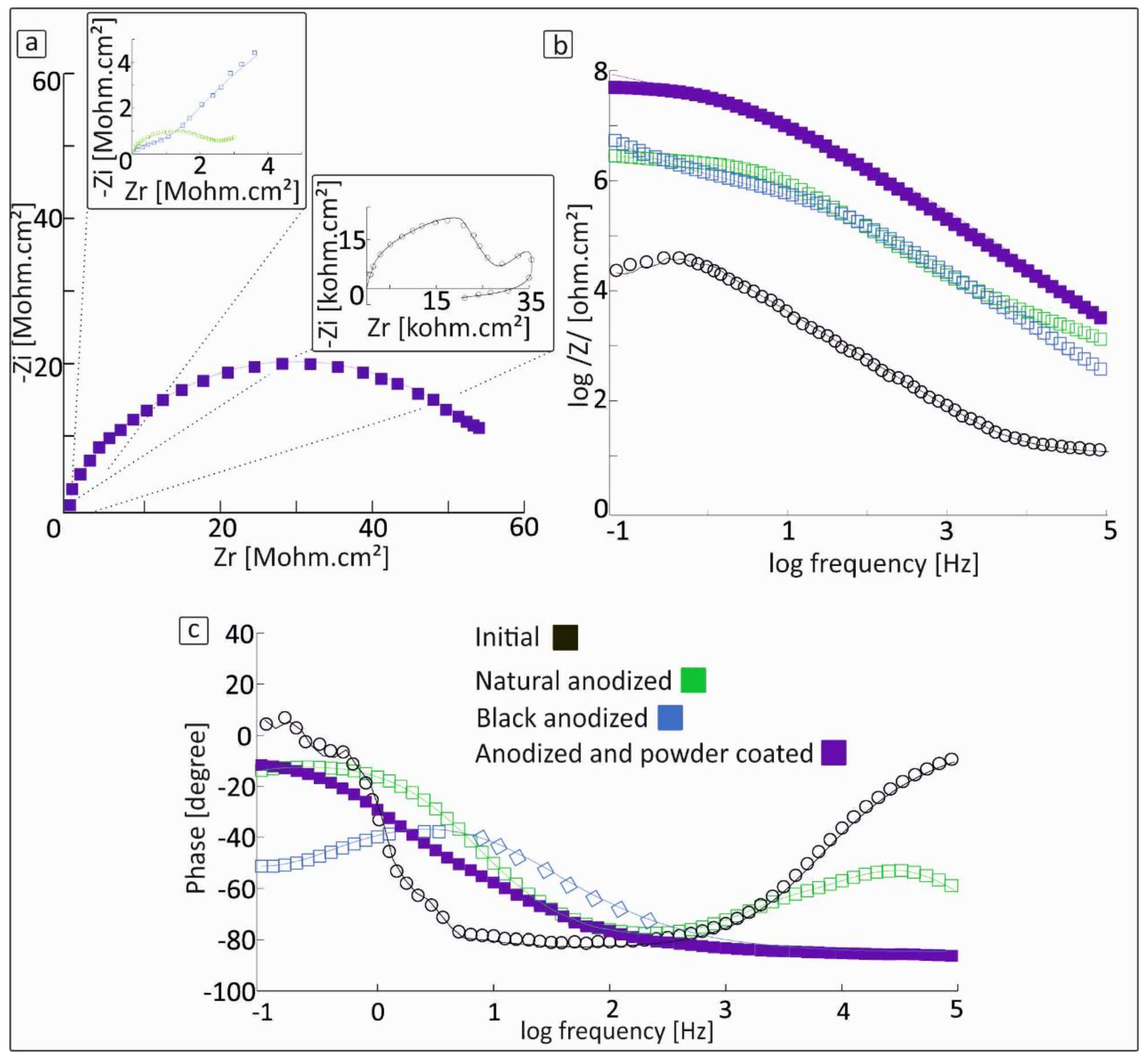
Electrochemical impedance spectroscopy (EIS) was used to investigate the corrosion behaviour of aluminium samples with different surface treatments, in a sodium chloride (NaCl) solution. Figure 3a displays the Nyquist, figure 3b Bode magnitude and figure 3c Bode phase angle, plots for initial (uncoated), anodized and anodized plus powder coated samples.
In the Nyquist plot (Figure 3a), the diameter of the semicircle is directly related to the polarization resistance, which serves as an indicator of corrosion protection efficiency. The sample treated with both anodizing and powder coating exhibits the largest semicircle diameter, indicating significantly higher impedance values and higher corrosion resistance. The initial samples show much smaller semicircles, showing that the material is more likely to corrode. The remaining samples, including those that were only anodized, show intermediate semicircle diameters, reflecting moderate levels of corrosion resistance. The Bode magnitude plot (Figure 3b) supports these observations. The anodized samples showed medium impedance, suggesting they provide some level of protection. The untreated samples had low impedance, indicating very limited or no effective surface protection. Also, a decrease in the low-frequency impedance typically reflects degradation or breakdown of the protective passive film, indicating loss of corrosion protection, which is consistent with the potentiodynamic polarization curves of the initial sample [27,29,30]. In the Bode phase angle plot (Figure c), the pre-anodized and powder coated sample demonstrates a broad plateau with a phase angle near -90°, which is characteristic of capacitive behaviour and indicates a stable dielectric interface [38]. The phase angle plots for the aluminium samples indicate the presence of at least two time constants. This suggests a complex protective system involving multiple electrochemical processes. The initial samples show a rapid phase drop and low phase angles, indicating limited corrosion protection [39,40]. Overall, the EIS results clearly illustrate the beneficial effect of combined anodizing and powder coating. This multilayer system provides enhanced corrosion protection. The white and black anodizing samples showed different levels of corrosion protection, likely due to differences in pigment type, thickness or porosity that affect their electrochemical properties. In the diagrams (Figure 3), the straight line represents the fitting curve, while the data points correspond to the experimental measurements.
3.3. Proposed Equivalent Electrical Circuit Models
To thoroughly analyze the electrochemical behavior of EN AW 6060 aluminum alloy samples subjected to different surface treatments, three distinct equivalent electrical circuits were constructed. Each circuit represents the distinct structural and electrochemical properties of the surface layers produced by each treatment, enabling a detailed analysis of the impedance spectroscopy results.
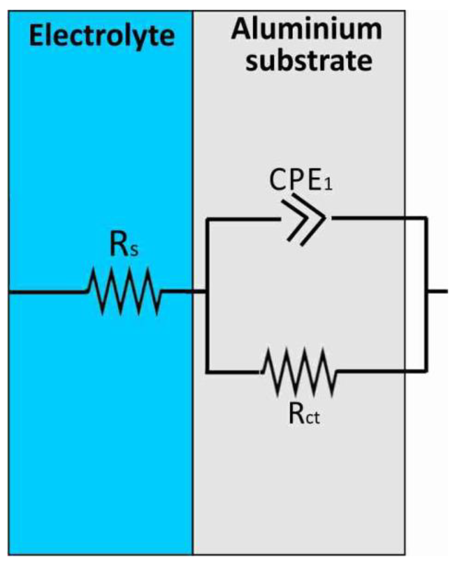
For the mill finished homogenized and aged sample, the simplest equivalent electrical circuit model was employed. This model includes the solution resistance (Rs), which represent the resistance of the electrolyte solution between the working and reference electrodes, a constant phase element (CPE₁) models the non-ideal capacitive behavior of the electrochemical double layer formed at the metal-electrolyte interface, describing surface heterogeneities and roughness. The charge transfer resistance (Rct) quantifies the resistance to electron movement during corrosion reactions occurring on the aluminum surface. This basic circuit effectively models the corrosion process in bare aluminum samples, where no protective layers affect the electrochemical reactions [41].
Figure 4.
Equivalent circuit representing the corrosion of uncoated aluminium samples.
In contrast, the anodized samples exhibit a more complex structure due to the presence of a porous oxide film. Therefore, a two-layer model was used to represent both the anodic film and the aluminum substrate. The first layer models the anodic oxide film, including Rs, a constant phase element (CPE₁) and a resistance (R₁) that characterizes the oxide layer’s dielectric and resistive properties. The oxide layer acts as a shield, stopping ions from passing through and improving corrosion resistance. Below the oxide film, the aluminum substrate is modeled by a second constant phase element (CPE₂) in parallel with a charge transfer resistance (Rct), reflecting the electrochemical activity at the metal interface beneath the oxide. Additionally, a Warburg diffusion element (W) is included for diffusion-controlled processes.
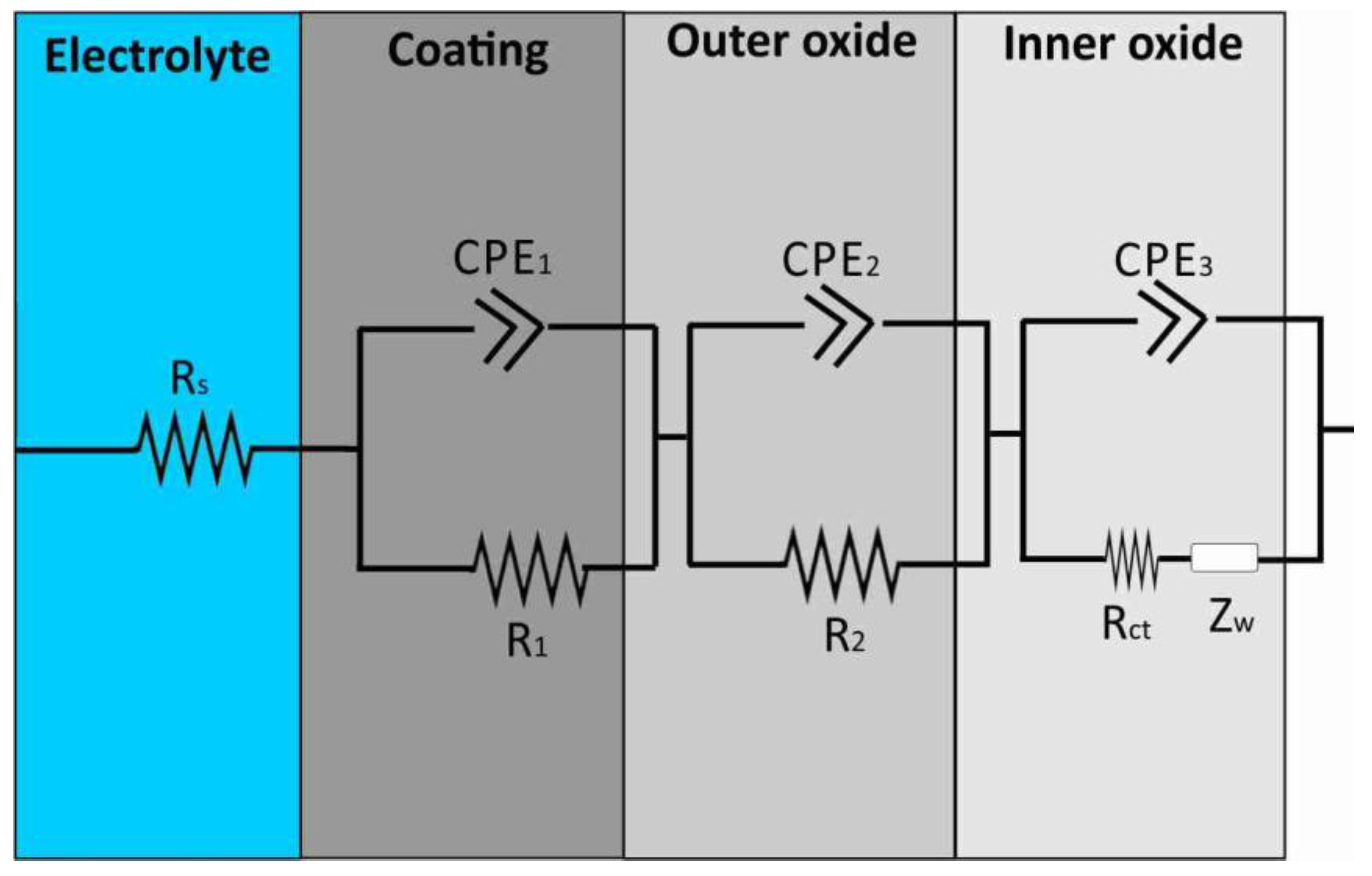
For the anodized samples that were further powder paint, a more detailed equivalent circuit was necessary for the representation of the multi-layered protective system. This circuit includes all the components found in the model used for anodized-only samples, Rs, CPE₁, R₁ for the anodic oxide layer and CPE₂, Rct, W for the substrate, while including an additional parallel branch consisting of CPE₃ and R₂. This additional branch represents the electrostatic powder coating, which forms a continuous, insulating barrier on top of the anodic film. The coating’s capacitive and resistive characteristics are modeled by the constant phase element (CPE₃) and resistance (R₂), respectively. This hierarchical modeling approach provides a deep understanding of how corrosion protection works in each surface treatment. By separating the effects of the electrolyte, anodic oxide layer, substrate and powder coating, the equivalent circuits allow for precise measurement of coating durability, oxide layer quality and corrosion resistance of the sample.
Figure 5.
Equivalent circuit representing the corrosion of anodized aluminium samples.
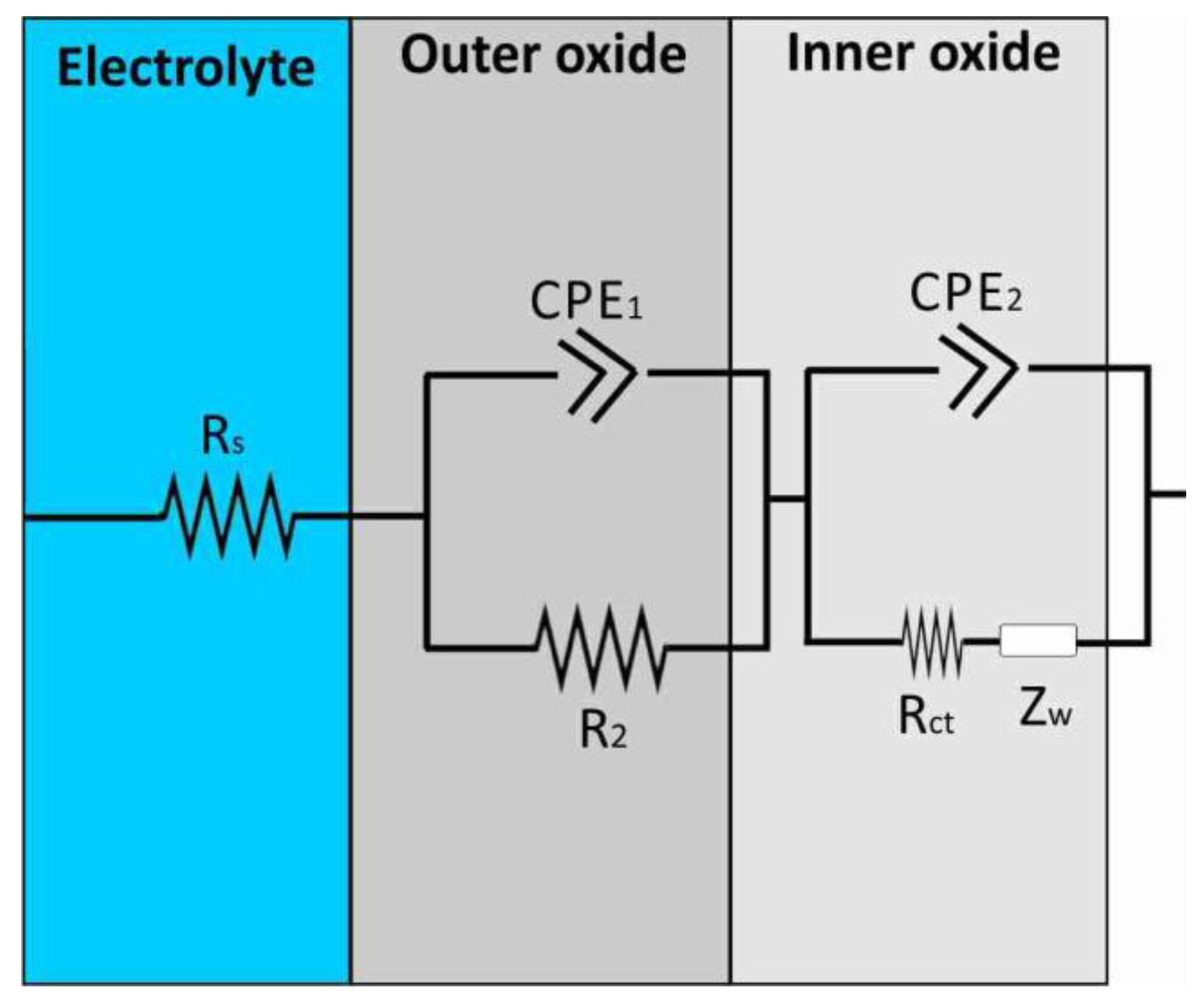
Figure 6.
Equivalent circuit representing the corrosion of anodized plus powder coated aluminium samples.
Figure 6.
Equivalent circuit representing the corrosion of anodized plus powder coated aluminium samples.
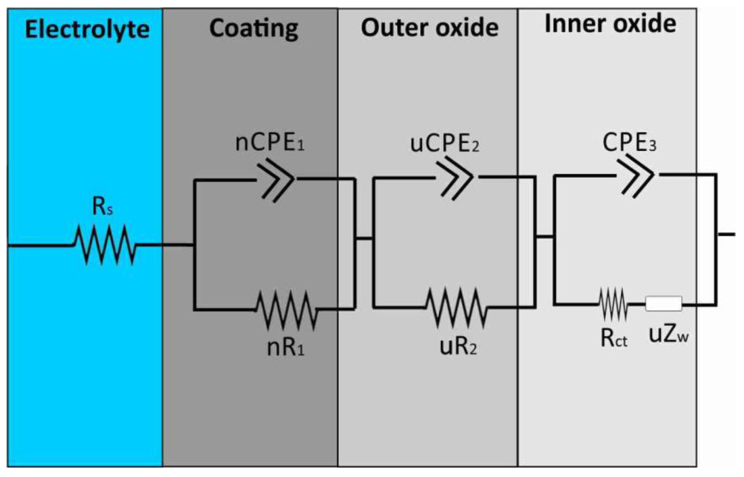
In addition to the specific equivalent circuits designed for each sample type, a more generalized equivalent circuit model was developed to include uncoated, anodized and anodized-plus-powder coated samples within a single, flexible model. This model adapts to different surface conditions by adjusting key parameters, particularly the variables u and n, which define the behavior of the constant phase elements and resistances for each case. The circuit includes the solution resistance (Rs), representing the electrolyte’s resistance, along with parameters R₁ and CPE₁, which correspond to the powder coated layer when present. The anodized layer is described by CPE₂ and R₂, capturing its capacitive and resistive properties, respectively. At the metal/electrolyte interface, the charge transfer resistance (Rct), a third constant phase element (CPE₃) model the non-ideal double-layer capacitance and a Warburg impedance element (Zw) is incorporated when necessary. This flexible equivalent circuit allows reliable fitting and interpretation of electrochemical impedance data for various surface treatments, offering valuable understanding of how each layer contributes and interacts within the overall corrosion protection system. The values of the equivalent circuit elements shown in Figure 4 are listed in Table 2. The model fits the experimental data well, meaning it can effectively describe the corrosion behavior of all aluminum samples in NaCl solution (with a standard error less than 10%) [42].
Figure 4.
(a) General equivalent circuit proposed for the corrosion behavior of uncoated, anodized and anodized plus powder coated samples, after immersion in 3.5 wt% sodium chloride solution (where n=0 and u=0 for uncoated, n=0 and u=1 for anodized, n=1 and u=1 for anodized plus powder coated, Al samples).
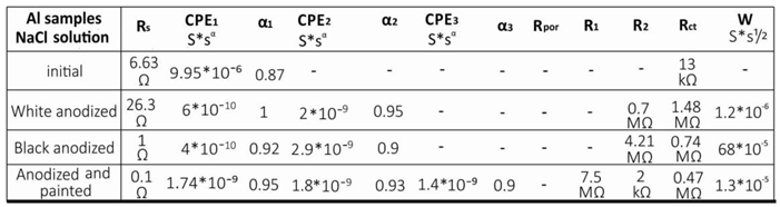
The uncoated sample exhibited an α value of 0.87 and a low charge transfer resistance (13 kΩ), indicating poor corrosion protection. Anodized samples showed medium corrosion protection. The natural one exhibited a nearly ideal dielectric response (α~1) suggesting a uniform oxide and Rct of 1.48 MΩ, while the black anodized sample showed higher resistance of the anodized layer but lower charge transfer resistance (0.74 MΩ) and α values, indicating reduced oxide integrity, possibly due to increased porosity or dye-related degradation. The high values of resistance indicate that the sealing process was highly effective [43]. The anodized and powder coated samples have the highest resistance (R₁ = 7.5 MΩ), which corresponds to the powder coating, an intermediate anodized-layer resistance (R₂ = 2 kΩ) and improved α values (0.93-0.95). These features show a strong combination of barrier effects, meaning better corrosion protection than anodizing alone. Low values of R2 indicate poor sealing quality of the porous layer, a fact also confirmed by the SEM images, which can be attributed to the fact that this is not the only protective layer, but an additional powder coating is applied on top. Overall, while the uncoated sample exhibited the lowest resistance, pre-anodized and powder coated samples show the most efficient protective behavior [44,45,46].
The thickness of the different layers can be estimated using the Eq. (1):
where εο = 8.85*10-14 F/cm the dielectric constant of vacuum, ε = 10 the relative dielectric constant of aluminum oxide, A the active surface and d the thickness of the layer. This equation is most accurate when the a is close to unity [42]. The calculated average values of natural anodized samples are d1 = 14.8 μm and d2 = 4.4 μm while d1 = 22 μm and d2 = 3 μm for the black anodized samples, with a total thickness of 19 μm and 25 μm, respectively, values that are very close to those measured from the SEM images. For the anodized and powder coated sample, the thicknesses of the anodized layers are d2 = 4.9 μm and d3 = 6.3 μm, with a total thickness of 11 μm, which coincides with and confirms the thickness measured from the SEM images.
C=εεοA/d
Table 2.
Parameters of the equivalent circuit elements (Figure 4) representing the corrosion behavior of uncoated, anodized, powder coated and anodized plus powder coated samples, after immersion in 3.5 wt% sodium chloride solution.
Table 2.
Parameters of the equivalent circuit elements (Figure 4) representing the corrosion behavior of uncoated, anodized, powder coated and anodized plus powder coated samples, after immersion in 3.5 wt% sodium chloride solution.
 |
4. Conclusions
This study focused on a systematic evaluation of the electrochemical behavior of aluminum samples with various surface treatments (untreated, anodized, pre-anodized and powder coated). Through electrochemical impedance spectroscopy (EIS) and equivalent circuit analysis, several findings were obtained:
- (1)
- Surface treatments significantly improve corrosion resistance. Anodized samples demonstrate approximately 30 times lower corrosion rate, while the anodized and powder-coated samples offer the highest protection, with a corrosion rate nearly 1000 times lower than that of the untreated aluminium.
- (2)
- The natural sample showed an almost ideal dielectric behavior (α ~ 1) and a charge transfer resistance of 1.48 MΩ, indicating a uniform oxide. The clear anodized sample had higher anodic resistance but lower Rct (0.74 MΩ) suggesting reduced oxide quality, likely due to porosity or dye effects.
- (3)
- The pre-anodized and powder coated samples demonstrates a complex multilayer electrochemical behavior that explains its superior protective performance. The outer layer exhibits very high resistance (7.5 MΩ) and excellent dielectric properties (α = 0.95), indicating an effective barrier against corrosion.
- (4)
- The high values of resistance for the anodized samples indicate that the sealing process was highly effective.
- (5)
- The calculated average thicknesses of the anodized layers confirm the SEM results.
References
- Jawalkar, C., Kant, S., & Yashpal. (2015). A review on use of aluminium alloys in aircraft components. i-Manager’s Journal on Material Science, 3(3), 33–38. [CrossRef]
- Egorkin, V. S. Vyaliy, I. E., Gnedenkov, A. S., Kharchenko, U. V., Sinebryukhov, S. L., & Gnedenkov, S. V. (2024). Corrosion properties of the composite coatings formed on PEO pretreated AlMg3 aluminum alloy by dip-coating in polyvinylidene fluoride-polytetrafluoroethylene suspension. Polymers, 16(20), 2945. [CrossRef]
- Peltier, F., & Thierry, D. (2024). Development of a reliable accelerated corrosion test for painted aluminum alloys used in the aerospace industry. Corrosion and Materials Degradation, 5(3), 427–438. [CrossRef]
- Gyarmati, G., & Erdélyi, J. (2025). Intermetallic phase control in cast aluminum alloys by utilizing heterogeneous nucleation on oxides. Metals, 15(4), 404. [CrossRef]
- Akhyar, A., Syahrial, A., & Syahrul, M. (2018). Cooling rate, hardness and microstructure of aluminum cast alloys. International Journal of Science and Engineering, 10(1), 1–6.
- Guo, F., Cao, Y., Wang, K., Zhang, P., Cui, Y., Hu, Z., & Xie, Z. (2022). Effect of the anodizing temperature on microstructure and tribological properties of 6061 aluminum alloy anodic oxide films. Coatings, 12(3), 314. [CrossRef]
- Cabral-Miramontes, J. Cabral-Miramontes, N., Nieves-Mendoza, D., Lara-Banda, M., Maldonado-Bandala, E., Olguín-Coca, J., Lopez-Leon, L. D., Estupinan-Lopez, F., Calderon, F. A., & Gaona Tiburcio, C. (2024). Anodizing of AA2024 aluminum–copper alloy in citric-sulfuric acid solution: Effect of current density on corrosion resistance. Coatings, 14(7), 816. [CrossRef]
- Bhat, K. U. Panemangalore, D. B., Kuruveri, S. B., John, M., & Menezes, P. L. (2022). Surface Modification of 6xxx Series Aluminum Alloys. Coatings, 12(2), 180. [CrossRef]
- Nazeri Abdul Rahman, C. J., Allene Albania Linus, B. H. M. Jan, A. Parabi, C. K. Ming, A. S. L. Parabi, A. James, N. S. Shamsol, S. B. John, E. F. Kushairy, A. A. Jitai, & D. F. A. A. Hamid. (2025). Corrosion resistance and electrochemical adaptation of aluminium in brackish peat water sources under seawater intrusion in the rural tropical peatlands of Borneo. Sustainable Chemistry for Climate Action, 6, Article 100074. [CrossRef]
- Li, Y., Li, W., Chen, W., Hong, H., & Zhang, T. (2025). Long-Term Corrosion Behavior of 434 Stainless Steel Coatings on T6061 Aluminum Alloy in Chloride Environments. Coatings, 15(2), 144. [CrossRef]
- Xu, L., et al. (2025). "Transition from pitting to intergranular corrosion of 2024-T351 aluminum alloy under atmospheric environment." Journal of Magnesium and Alloys. https://www.sciencedirect.com/science/article/pii/S2238785425005150.
- Guo, Y., et al. (2025). "Corrosion mechanism of aviation aluminum alloy 7B04 under sulfate-reducing bacteria." RSC Advances, 15, 12230–12239. https://pubs.rsc.org/en/content/articlehtml/2025/ra/d5ra02115d.
- Zhao, J., et al. (2023). "Atmospheric corrosion behavior of typical aluminum alloy at low temperature." Metals, 13(3), 277. https://www.mdpi.com/2075-4701/13/3/277.
- Malaret, F. (2022). Exact calculation of corrosion rates by the weight-loss method. Experimental Results, 3, 1–16. [CrossRef]
- Cabrini, M., Lorenzi, S., Pastore, T., Pellegrini, S., Burattini, M., & Miglio, R. (2017). Study of the corrosion resistance of austenitic stainless steels during conversion of waste to biofuel. Materials, 10(3), 325. [CrossRef]
- Gulbrandsen, E. (2025). Quantification of hydrogen evolution in corrosion testing by buoyancy measurements [Preprint]. Research Square. [CrossRef]
- Zhang, L., Li, J., & Wang, H. (2022). Experimental study on neutral salt spray accelerated corrosion of metal protective coatings for power-transmission equipment. Materials, 15(4), 1234.
- Singh, A., Kumar, P., & Sharma, R. (2021). Corrosion resistance evaluation of coated aluminum alloys using salt spray and electrochemical methods. Journal of Coatings Technology and Research, 18(2), 567-578.
- Chen, Y., Liu, X., & Zhao, F. (2020). Salt spray testing and electrochemical impedance spectroscopy for corrosion behavior analysis of anodized aluminum. Surface and Coatings Technology, 385, 125391.
- Patel, S., Mehta, D., & Joshi, M. (2019). Effect of organic coatings on corrosion resistance of aluminum alloys evaluated by salt spray and electrochemical tests. Progress in Organic Coatings, 132, 146-154.
- Kim, J. Lee, S., & Park, C. (2018). Corrosion performance of hybrid organic-inorganic coatings on aluminum alloys in salt spray tests. Corrosion Science, 137, 14-23.
- Jáquez-Muñoz, J. M. Gaona-Tiburcio, C., Méndez-Ramírez, C. T., Martínez-Ramos, C., Baltazar-Zamora, M. A., Santiago-Hurtado, G., Estupinan-Lopez, F., Landa-Ruiz, L., Nieves-Mendoza, D., & Almeraya-Calderon, F. (2024). Electrochemical Noise Analysis: An Approach to the Effectivity of Each Method in Different Materials. Materials, 17(16), 4013. [CrossRef]
- Zhang, L. Wang, F., & Chen, Y. (2021). Application of electrochemical noise technique in corrosion monitoring of metals: A review. Journal of Materials Science & Technology, 70, 140–154. [CrossRef]
- Li, H., Sun, Y., & Gao, Y. (2022). Electrochemical noise analysis of corrosion behavior of magnesium alloys in simulated body fluid. Corrosion Science, 195, 109987. [CrossRef]
- Xu, X., Sun, W., & Wang, H. (2023). Using electrochemical noise technique to evaluate corrosion inhibition performance of novel coatings on steel. Surface and Coatings Technology, 456, 129720. [CrossRef]
- Rivera, A. L. & Castaño, V. (2012). Corrosion analysis by electrochemical noise: A teaching approach. Journal of Materials Education, 34, 151–159.
- Barsoukov, E. & Macdonald, J. R. (Eds.). (2018). Impedance spectroscopy: Theory, experiment, and applications (2nd ed.). Wiley. [CrossRef]
- Lasia, A. (2014). Electrochemical impedance spectroscopy and its applications. In B. E. Conway, R. E. White, & J. O’M. Bockris (Eds.), Modern aspects of electrochemistry (pp. 143–248). Springer. [CrossRef]
- Boukamp, B. A. (2015). Electrochemical impedance spectroscopy (EIS): An overview. Journal of Electroceramics, 35(2), 139–152. [CrossRef]
- Sherif, E.-S. M., & Karim, N. A. (2020). Application of electrochemical impedance spectroscopy for corrosion monitoring and evaluation of corrosion inhibitors. Materials Chemistry and Physics, 254, 123464. [CrossRef]
- Bjørgum, A. Lapique, F., Walmsley, J. C., & Redford, K. (2003). Anodizing as pre-treatment for structural bonding. International Journal of Adhesion and Adhesives, 23(5), 401–412. [CrossRef]
- Ofoegbu, S. U. Fernandes, F. A. O., & Pereira, A. B. (2020). The Sealing Step in Aluminum Anodizing: A Focus on Sustainable Strategies for Enhancing Both Energy Efficiency and Corrosion Resistance. Coatings, 10(3), 226. [CrossRef]
- Raffin, F. Echouard, J., & Volovitch, P. (2023). Influence of the Anodizing Time on the Microstructure and Immersion Stability of Tartaric-Sulfuric Acid Anodized Aluminum Alloys. Metals, 13(5), 993. [CrossRef]
- Hsing-Hsiang Shih, Yu-Chieh Huang, Study on the black electrolytic coloring of anodized aluminum in cupric sulfate, Journal of Materials Processing Technology, Volume 208, Issues 1–3, 2008, Pages 24-28. [CrossRef]
- Mrówka, G. Sieniawski, J., & Wierzbińska, M. (2007). Analysis of intermetallic particles in AlSi1MgMn aluminium alloy. Journal of Achievements in Materials and Manufacturing Engineering, 20(1-2), 283–286.
- Bara, M. Niedźwiedź, M., & Skoneczny, W. (2019). Influence of Anodizing Parameters on Surface Morphology and Surface-Free Energy of Al2O3 Layers Produced on EN AW-5251 Alloy. Materials, 12(5), 695. [CrossRef]
- Amin, M. A. (2009). Metastable and stable pitting events on Al induced by chlorate and perchlorate anions—Polarization, XPS and SEM studies. Electrochimica Acta, 54(6), 1857–1863. [CrossRef]
- Radon, A. Ciuraszkiewicz, A., Łukowiec, D., Toroń, B., Baran, T., Kubacki, J., & Włodarczyk, P. (2025). From micro to subnano scale: Insights into the dielectric properties of BiOI nanoplates. Materials Today Nano, 100649. [CrossRef]
- Iqbal, M. A. Maia, F., Matykina, E., Arrabal, R., Mohedano, M., & Vega, J. M. (2025). Active corrosion protection of AA2024T3 by the synergy of flash-PEO/Ce coating and epoxy coating loaded with LDH/eco-friendly gluconate. Progress in Organic Coatings, 206, 109359. [CrossRef]
- Rodič, P. Kapun, B., & Milošev, I. (2024). Complementary corrosion protection of cast AlSi7Mg0.3 alloy using Zr-Cr conversion and polyacrylic/siloxane-silica multilayer coatings. npj Materials Degradation, 8, 58. [CrossRef]
- Lazanas, A. Ch. & Prodromidis, M. I. (2023). Electrochemical impedance spectroscopy — A tutorial. ACS Measurement Science Au, 3, 162–193. [CrossRef]
- Stergioudi, F. Vogiatzis, C. A., Gkrekos, K., Michailidis, N., & Skolianos, S. M. (2015). Electrochemical corrosion evaluation of pure, carbon-coated and anodized Al foams. Corrosion Science, 91, 151–159. [CrossRef]
- Huayuelong Huang, Hong Shih, Huochuan Huang, John Daugherty, Shun Wu, Sivakami Ramanathan, Chris Chang, & Florian Mansfeld. (2008). Evaluation of the corrosion resistance of anodized aluminum 6061 using electrochemical impedance spectroscopy (EIS). Corrosion Science, 50(12), 3569–3575. [CrossRef]
- Córdoba-Torres, P. (2017). Relationship between constant-phase element (CPE) parameters and physical properties of films with a distributed resistivity. Electrochimica Acta, 225, 592–604. [CrossRef]
- Chang, B.-Y. (2020). Conversion of a constant phase element to an equivalent capacitor. Journal of Electrochemical Science and Technology, 11(3), 318–321. [CrossRef]
- Huang, Y., Shih, H., Huang, H., Daugherty, J., Wu, S., Ramanathan, S., Chang, C., & Mansfeld, F. (2008). Evaluation of the corrosion resistance of anodized aluminum 6061 using electrochemical impedance spectroscopy (EIS). Corrosion Science, 50(12), 3569–3575. [CrossRef]
Figure 1.
(a) Microstructure of the matrix of aluminium sample, cross-section of (b, c) anodized and (d) pre-anodized and powder coated Al samples.
Figure 1.
(a) Microstructure of the matrix of aluminium sample, cross-section of (b, c) anodized and (d) pre-anodized and powder coated Al samples.
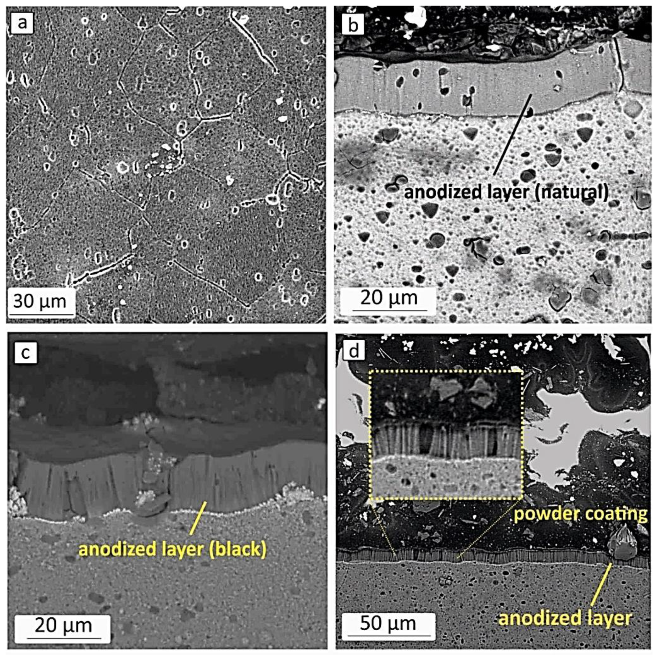
Figure 3.
(a) Nyquist (b) Bode impedance magnitude and (c) Bode phase angle plots of aluminium samples with different surface treatments after immersion in 3.5 wt% sodium chloride solution.
Figure 3.
(a) Nyquist (b) Bode impedance magnitude and (c) Bode phase angle plots of aluminium samples with different surface treatments after immersion in 3.5 wt% sodium chloride solution.
Disclaimer/Publisher’s Note: The statements, opinions and data contained in all publications are solely those of the individual author(s) and contributor(s) and not of MDPI and/or the editor(s). MDPI and/or the editor(s) disclaim responsibility for any injury to people or property resulting from any ideas, methods, instructions or products referred to in the content. |
© 2025 by the authors. Licensee MDPI, Basel, Switzerland. This article is an open access article distributed under the terms and conditions of the Creative Commons Attribution (CC BY) license (http://creativecommons.org/licenses/by/4.0/).
Copyright: This open access article is published under a Creative Commons CC BY 4.0 license, which permit the free download, distribution, and reuse, provided that the author and preprint are cited in any reuse.


