
Submitted:
17 July 2025
Posted:
17 July 2025
You are already at the latest version
Abstract
The quadcopters are extremely sensitive to motor failures, which may occur secondary to broken propellers or motor faults during the flight operation. These faults alter the dynamics of the quadcopters, whereas the control algorithms generally used for controlling are no longer as effective. This paper presents a reliable fault-tolerant controller that can handle quadcopter motor failures in order to address these issues. The proposed control system uses a nonlinear disturbance observer-based sliding mode control (NLDO-SMC) to significantly manage the quadcopter’s rotational dynamics, while an integrated back-stepping controller (IBSC) is employed to supervise the translational movement. The developed nonlinear formulation’s NLDO-SMC, predicts motor failures and keeps the system resilient to unforeseen circumstances and disruptions that can arise while the vehicle is in the air. The suggested fault-tolerant control paradigm is validated by hardware-in-the-loop (HIL) experimental investigation and extensive simulations. The controller’s performance in real-world scenarios is thoroughly examined using the FPGA model. The results indicate that the controller can effectively deal with the effects of motor faults and restore control over the quadcopter’s stability. The proposed controller achieves robustness to up to 50% fault in a single motor, and the quadcopter follows the desired path with well-predicted rotation angles, thus proving the ability of the model to increase fault tolerance and operational safety under fault conditions.
Keywords:
fault tolerance
; quadcopter
; integral back-stepping control
; nonlinear disturbance observer sliding mode control
; FPGA implementation
1. Introduction
Unmanned Aerial Vehicles (UAVs) have revolutionized the world and are used in several fields like agriculture [1], environmental monitoring [2], military services [3], and many more, however, their control and stability are often compromised in the presence of fault scenarios and they remain infrequently used in their more conventional applications [4]. To guarantee safety, the design of fault-tolerant control systems for the UAV is a topic of research. To enhance fault detection, estimation, and compensation for UAV deployment, scientists deployed different linear and non-linear control system models [5]. Several nonlinear control strategies include sliding mode control (SMC) and observer-based methods to cope with the model uncertainties and external disturbances to minimize downtime catastrophe faults while increasing the knowledge level of all autonomous systems that are struggling at high altitudes [6]. Arificial intelligence based method also enhances safety [7], responsibility [8], generalization [9] of UAV by using advanced computer vision and deep learning techniques [10].
UAVs are a type of aircraft suited for long and high-speed missions and have transformed from a military concept to a commercial and industrial one [11]. UAVs that give lift employing forward motion are called fixed-wing UAVs while rotary-wing UAVs (also known as helicopters or multirotors) generate lift through the rotation of blades [12]. Hybrid UAVs combine fixed and rotary-winged for efficient long-range flight [13]. Fixed-wing, rotating-wing, and bird-like flying are commercially available UAVs. The onboard navigation systems are constrained by the variety of UAV types, with the main requirements being size, weight, accuracy, and availability of location [14]. Quadcopters are used as a research target because they can handle non-linearities and unexpected faults, the same way flight dynamics and flexibility are what make them unique compared to other planes [15]. Advanced controlling techniques such as model predictive, adaptive and sliding mode control, etc. have replaced traditional ones like PID controllers. Since mission-critical applications require FTC, there is a gap in integrating nonlinear control with real-time fault detection and compensation. Current FTC methods suffer from high computational complexity, late fault detection, and less efficient fault compensation when the condition is severe [16]. Reliability and validation in real-world scenarios are impeded through most research, which relies on simulations only.
This research aims to create a fault-tolerant control system for a quadcopter so that the faults in the motor can be compensated. Hardware-based fault compensation analysis is lacking in the present systems, so designing a hybrid control model that stabilizes the quadcopter and performs successfully despite actuator faults in real-time is a need of time. Reliable control systems for quadcopters with dynamic handling requirements and motor failure pose a major challenge. In this study, non-linear disturbance-based sliding mode control (NLDO-SMC) and integral back-stepping control (IBSC) for quadcopter translational and rotational motion control are simulated, and FPGA-based HIL experiments are used to verify the feasibility and reliability of the designed model.
The paper is divided into seven sections: introduction, related work, dynamics of the quadcopter, methodology, results, discussion, and conclusion. This work includes the mathematical modeling of motor faults and quadcopter parameters, followed by motor fault modeling. The identified methodology consists of a proposed control model and stability analysis. Results are generated in simulation and FPGA experiments in the case of motor faults is presented. Comparative analysis of HIL experiments and simulation-based experiments is also discussed.
2. Related Work
In this section, several papers published in the last decade are discussed and summarized to understand the topic. Motor faults severely affect the controllability of UAVs, and many academic researchers have proposed different fault-tolerant control strategies to guarantee UAVs’ controllability during faulty conditions [17]. Controlling a quadcopter UAV is a challenging task because it can no longer be fully controlled after one motor fails. However, they are still fully controllable when there is a specific partial failure of a motor [18]. An FTC algorithm is necessary for the safe landing and operation of multirotor UAVs when there are motor malfunctions [19]. An active disturbance rejection control technique is proposed which allows quadrotors to maintain a desired trajectory of height and attitude even when there are outside disturbances. The controller has state error feedback (SEF), an extended state observer (ESO), and a tracking differentiator (TD). Results from experiments and numerical simulations confirm that the suggested controller works well [20]. A two-stage control system is used for analysis, an adaptive observer combined with a nonlinear observer, and for high-frequency control switching and chattering for quadrotors an SMC with sigmoid function is used in the event of a single rotor failure. This paper aims to demonstrate the effectiveness and viability of the suggested method by presenting simulation results only [21].
The following are the contributions of this paper, which are based on research gaps from the reviewed literature: First, a nonlinear observer is developed to estimate the impact of motor faults on the control algorithm; second, a sliding mode controller and the nonlinear observer are combined to create a novel FTC strategy for a quadrotor’s rotational control; third, an integral backstepping controller is designed for translational motion control; fourth, the suggested hybrid control strategy is implemented on a custom quadcopter testbed; and fifth, the fault-tolerant controller is validated through FPGA-Based HIL experiment. Table 1 summarizes some recently published work.
3. Quadcopter’s Dynamics
Understanding the dynamics and control systems of quadcopters requires mathematical modeling. Quadcopter systems are inherently nonlinear, with intricate connections between translational and rotational motions. The quadcopter’s behavior is governed by a nonlinear mathematical model with four rotors, allowing it to perform six degrees of freedom (DOF) [33]. This flexibility enables quadcopters to perform various aerial tasks. The configuration of quadcopter propellers, commonly "+" and "x", plays a crucial role in stability and control as shown in Figure 1 [34].
This work analyses a cross-configuration quadcopter, having four propellers at the corners of a square and spinning the pairs in opposite directions to cancel torque. This layout makes control logic simple and increases system stability. The desired directional orientation and trajectory of the quadcopter is realised by modulating the rotational speeds of the four motors, which consequently create the rotational forces and moment components to execute the required maneuvers [35]. Vertical translation is controlled by changing the rotational speeds of all four rotors together, and roll, pitch, and yaw are caused by the rotation of longitudinal, lateral, and transverse axes, respectively. Newton-Euler equations allow deriving a robust mathematical model of the platform, which is essential to develop advanced control schemes and achieve dependability under disturbances of the system [36]..
Figure 2 illustrates the quadcopter’s inertial frame and body frame, with , , and representing roll, pitch, and yaw, respectively. Two opposite propellers rotate clockwise to control the quadcopter’s motion, while the remaining two rotate counterclockwise. Altitude control involves adjusting the speeds of all four rotors upwards or downwards, depending on the desired effect. For forward movement, increase rotor speeds (1,2) while decreasing (3,4), and for backward movement, increase rotor speeds (3,4) and decrease (1,2). To turn the quadcopter left or right, increase or decrease rotor speeds (1,3) and decrease or increase rotors (2,4) [37].
3.1. Quadcopter Mathematical Modeling
In addition to exploring the dynamic equation of UAV and clarifying its physical properties, this section presents the mathematical model that determines the behavior of a quadcopter, with a particular emphasis on its four-rotor cross configuration. Equations (1) and (2), respectively, show the quadcopter’s translational and rotational dynamics in the body frame [38].
Translational Dynamics
Rotational Dynamics
Euler Equations
UAVs may be divided into two subsystems: a) Subsystem that rotates: This includes the Euler angles that determine the orientation of the UAV. In particular, the yaw angle around the z-axis, the pitch angle around the y-axis, and the roll angle around the x-axis. b) translational subsystem: here, this work focuses on the quadcopter’s spatial positioning, which includes its altitude (z-axis), and its x and y coordinates. The position vector V ∈ can be formally represented as conversion from earth frame to body frame is possible. Equation (4) demonstrates the transition between Earth and body frames.
Equation (5) provides R, the rotation matrix from the body to the inertial frame.
Equation (6) shows the relationship between the angular and the Euler angle rates.
Equation (7) represents the dynamic model of the quadcopter, which includes the x, y, and z motions as a consequence of translational and rotational movement.
Equation (8) illustrate the rotational matrix for Euler angles:
The following matrix operation in (9) is used to acquire the transformation matrix for angular velocities from the earth frame to the body frame:
Equations (10) and (11) present the aerodynamic forces and moments of the quadcopter. The translational drag coefficients are , and and rotational drag coefficients are , and are provided in Table 2.
The quadcopter’s state space vector can be determined through
Additionally, the state space vector may be expressed as follows:
A quadcopter can rotate in several ways depending on its angular speed, measured in radians per second. The following is the complete set of equations for angular speeds regarding the four control inputs.
3.2. Rotor dynamics and motor fault modeling
To counteract the change in rotational speed caused by the motor dynamics, the thrust produced by the motors is thought of as a first-order system:
In (15), represents the rotational speed of each motor in rpm, is the motor gain, is the nth motor input, and s represents the Laplace variable, regulating the motor.
The propeller’s diameter, rotational speed, and the aerodynamic characteristics of the blades all affect the motors’ torque and thrust force in the following ways:
where and are the thrust and drag coefficients, is the air density, and D is the propeller diameter. The numerical numbers b and d are introduced in Table 2. By considering the inverse, the motor mixer expression is derived, which determines the rotational speed of each rotor with intermediate autopilot outputs (u).
The autopilot outputs (u) must be converted into motor inputs for quadcopter speed controls and applied to each motor’s motor, ensuring a matching PWM signal. A partial failure on the nth motor may result in rotor damage or deterioration of the motor’s performance, creating internal parametric uncertainty and influencing the force and moment of the motor as shown below.
Bounded fluctuations of the motor efficacy that respect their nominal values are shown by the variables and . They might be stated like this: indicates the ith motor fault, -b ≤≤ 0, and -d ≤≤ 0. It should be noted that the previously described fault model is only used in the simulation; neither the length nor the severity of the issue are provided to the control algorithm. Thus, the real signal (T) produced by the faulty actuator is as follows:
While , which varies from 0 to 1, indicates the fault’s severity, represents the fault time at which the fault occurs. Whereas indicates total motor damage, indicates no motor defect as shown in the (20).
3.3. Physical Parameters of the Quadcopter
This section presents the physical parameters of a quadcopter to explain its dynamics and to be able to design a proper control system, as shown in Table 2. The parameters studied are the mass, arm length, drag factor, drag coefficients, inertial moments, as well as the motor speed. Taken together, the three quantities allow aerodynamic forces to be modelled, enable estimating energy use, and are used to provide the static stability. The inertial moments around the main axes, which are the roll, the pitch, and the yaw, and also the motor speed are also assessed, providing control algorithms of precision but also of robustness. The results form the basis of a nonlinear control architecture that is able to generate high-accuracy simulations and manage fault situations.
4. Methodology
This work aims to implement a nonlinear control technique to create a fault-tolerant control system for quadcopter UAVs. First, the UAV is chosen, and then factors like mass, moment of inertia, and motor characteristics are chosen. Stability and control under a range of operating circumstances, including fault-tolerant operations, are features of the nonlinear control system. For the control algorithm to operate properly, the controller has an NLDO-SMC that enables real-time state and fault estimates. When a quadcopter has a motor failure, the performance of the nonlinear control system is evaluated, demonstrating the maximum fault tolerance for steady flight. Each motor’s flaws are taken into account in the simulation, and the suggested control system is put into practice using the hardware FPGA model. In order to illustrate the advantages of nonlinear control in coordinating fault detection, estimation, compensation, and system recovery, the outcomes of nonlinear control are based on several fault analysis scenarios, with the maximum values being recorded and compared. MATLAB/Simulink is used to simulate the quadcopter model, and the FPGA board is used to implement the IBSC and NLDO-SMC. This systematic technique guarantees a thorough investigation of the quadcopters’ fault-tolerant capacities under various fault levels, leading to significant findings on the advantages of nonlinear control algorithms in UAV explanations.
Fault tolerance and sophisticated control system methods are included in the suggested quadcopter control system. The integrated back-stepping controller (IBSC), which regulates translational motion, uses the trajectory planner on the quadcopter to deliver both the intended and actual trajectory information while in flight. A simulated actuator failures block processes the signals for altitude and horizontal movement direction inputs that are provided by the IBSC. Rotational motion control is accomplished via the non-linear disturbance observer (NLDO), which is firmly intended to monitor desired trajectories in spite of system actuators that may malfunction and cause disturbances. A quadcopter’s fault-tolerant control system provides strong performance even in the event of motor failures by combining the NLDO-SMC for rotating motion control with the IBSC approach for translational motion. These controllers fix issues with a quadcopter’s attitude and position stability, ensuring that it remains stable even when there are defects or disruptions. Two sizable control loops are taken into account in quadcopter dynamics: one governs rotating motion, while the other governs translational motion. In spite of equipment malfunctions, both tactics work together to keep the UAV stable and on the intended course. Lyapunov stability is taken into account in the design and analysis of the suggested scheme for the fault-tolerant control system of a quadcopter UAV, both in the case of the NLDO-SMC for rotating motion and the IBSC for translational motion. Figure 3 shows the block diagram of the proposed system.
4.1. Integral Backstepping Controller Design for Translational Motion Control
Three-dimensional Newton-Euler equations are used to model the dynamics of the translational control in quadcopter systems. The thrust forces of the rotor serve as control inputs [39]. Because it gradually stabilizes the system, backstepping is a recursive design process that works well for nonlinear systems like UAVs. To compensate for steady-state mistakes and improve the system’s capacity to reject disturbances and handle faults, integral backstepping control adds an integral action to conventional backstepping controls. The integrated action modifies the overall thrust in the event of a motor failure to keep the quadcopter in the intended position [40]. The quadcopter’s translational motion is stabilized by this architecture. Below is a discussion of the system’s (y-axis) IBSC design.
The tracking error variable for y and its derivative is
To make sure the stability of the quadcopter the Lyapunov candidate function is used
The virtual control input for the stability of is
putting the value of , in (23)
Further, to stabilize the second error state, the stabilizing function is
the second tracking-error variable for is
from (23)
Take derivative of (27) and put (21), we get
To select augmented Lyapunov candidate function
derivative of is
Finally, the control input is obtained as shown below
Putting into (31), the Lyapunov function becomes
According to (34), the Lyapunov function derivative is negative, indicating the stability of the control system that was constructed. Additionally, the above procedure for is applied to derive the expressions of and as shown in (35) and (37) respectively. As seen in (36) and (38), the Lyapunov function derivatives are also negative, demonstrating the stability of the suggested system.
Accordingly, the Lyapunov stability idea has been applied naturally in the back-stepping control work to develop the stabilizing controller for system dynamics at each step [41]. A Lyapunov function that reflects the system’s "energy" or position inaccuracy is chosen at each stage in the back-stepping process. Usually, it might be the total of squared errors in velocity and location. For instance, the Lyapunov function for the y-axis may be:
To ensure stability, its time derivative must be at least negative semi-definite, meaning that the system’s energy decreases with time.
The control input, or thrust along the y-axis, is represented by in (40), the error in the z-direction or altitude by , the time derivative of this error by , and ≤ 0 for the system to be stable. The altitude error decreases with time because the backstepping controller guarantees that such a derivative is negative, which results in asymptotic stability. After that, steady-state mistakes are eliminated by adding an integral action. The Lyapunov function of this system with the position error integral may have an additional component. Under continuous disturbances or motor failures, the derivative of this extended Lyapunov function ensures that, in addition to maintaining system stability, it also drives the position error to zero.
4.2. Rotational Motion Control using Nonlinear Disturbance Observer-Based Sliding Mode Control (NLDO-SMC)
A quadcopter’s angular orientation affects its attitude dynamics. According to Euler’s equations of rotational motion, it may be analytically represented by Euler angles: roll , pitch , and yaw [42]. The UAV’s rotation around its center of mass is described by these dynamics. The torques supplied by the motors are connected with and dictate the rotational dynamics. Additionally, the SMC design for looks like this:
First, we define the tracking-error variable for :
Taking its derivative:
Now select a sliding surface :
Put the value of from (43) in (45)
Further, the derivative of is
putting the value of
The sliding surface is set to zero while developing SMC, . The switching control component and the control input of a continuous control law are displayed in (50) and (51), respectively.
After adding to , we get
Likewise, the SMC design for and is determined, and the corresponding mathematical forms are displayed in (53) and (54).
In the mathematical form of NLDO-SMC, the constant values are given in Table 3.
The purpose of the sliding mode control law is to steer a system toward a sliding surface while preserving stability. For stability, the derivative of the squared sliding surface, which is a Lyapunov function, must be negative [43]. The control law can be created to stabilize the system and lower rotational errors to lower the Lyapunov function. Control input is corrected based on the observer’s estimation of system states or defects. The observer may be designed using a Lyapunov-based method, which guarantees boundedness and asymptotic convergence of estimate errors [44].
By calculating the percentage decrease in thrust or torque, a nonlinear disturbance observer can infer unmeasured states or faults, like motor faults [45]. The nonlinear function f(x,u) affecting quadcopter dynamics, including errors, uncertainties, and disturbances, is estimated by this nonlinear observer and supplied into the SMC for appropriate control action [46]. The following are the mathematical formulas for NLDO dynamics:
However, the discretized form of the model is used as shown in (56).
The dynamics of state estimation error are obtained by defining an error function, , which is the difference between the estimated and real states. Calculating the derivative of the state estimation error yields the following results, where L represents observer gain, , and guarantee observer dynamics stability.
A nonlinear observer is proposed to estimate the function , which characterizes the quadcopter’s dynamics. The observer dynamics are defined as:
where L is the observer gain matrix. The observer states and nonlinear function estimations are given by:
where
The stability analysis for the Observer is defined by the error’s dynamics. The state estimation error’s dynamics, which are described as , may be stated as follows:
The below requirements must be fulfilled for the observer to stay dynamically stable:
- The left-hand plane of the complex domain must include the matrix’s eigenvalues .
- The nonlinear function and its derivatives (,) should be bounded.
- is the transfer function which must be strictly stable, in this the Laplace transform is shown by .
The eigenvalues of the matrix are chosen to be in the left half-plane and are [-1.5 -1.6 -9.9 9.0 -1.9 -2.7 -3.3 -6.4 -2.5 -6.4 -5.8 -6.2] to guarantee the observer’s dynamic stability. It is assumed that the system satisfies BIBO stability. This guarantees the boundedness of the nonlinear function and its derivatives:
If the first two requirements are met, then is assumed to be strictly stable. The observer gain matrix L that corresponds to the eigenvalues mentioned above is as follows:
The FPGA board’s discretized implementation of NL-DO is provided as in Equation 63;
where the sampling period is denoted by T.
As seen in Figure 4, the NLDO-SMC and IBSC are implemented on the Nexys A7 FPGA model, while the UAV model, trajectory planner, and actuator failures are simulated in MATLAB/Simulink.
The quadcopter uses translational control (back-stepping) to prevent motor failures and preserve stability. Utilizing the Lyapunov functions, the system employs a Fault Tolerant Control System based on Lyapunov Stability and Fault Tolerant Control, which guarantees system stability under both nominal and fault situations. According to the Lyapunov function, system energy gradually drops, causing the system to approach a stable state. Lyapunov stability for translational motion is used to manage the quadcopter’s position and ensure that it stays in the appropriate location. Lyapunov stability is used for globally stable orientation control, including attitude pitch roll and yaw, even if the motors fail. The system’s control signals are designed to be stable and resilient to disturbances, as well as to eliminate uncertainties and disruptions.
The actual hardware configuration employed in this experiment is depicted in Figure 5. With this capacity, the Nexys A7™ board—a robust platform built on Xilinx’s Artix-7® Field Programmable Gate Array (FPGA) is used to implement the specified control system. The screen shows the proposed control system, quadcopter model, trajectory planner, and simulated fault actuator. The IBSC and NLDO-SMC deployed on the FPGA board to confirm experimental results, whereas the quadcopter model operated in MATLAB/Simulink.
The proposed controller is based on real-time computation and uses an observer and a set of fault compensation algorithms. They are innately nonlinear and computationally intensive modules, and thus, they are computationally intensive. These computations are implemented on an FPGA model, the parallel nature of which dramatically increases the efficiency of the computation thus reducing the load on the CPU compared with fully software equivalent solutions. After synthesis of the controller and observer design using Xilinx Vivado, the following hardware resources of the FPGA board were noted to have been required to address all the computing needs:
31800 LUT (Look-up Tables)
4998 FF (Flip Flops)
26 BRAM (Block RAMs)
240 DSP Blocks
5. Results
This section presents the results of a fault-tolerant control technique for a quadcopter under different failure circumstances. In both simulation-based and FPGA hardware-based analyses, the controller’s capacity to sustain stability and trajectory tracking in the face of motor failures is assessed. The controller’s fault detection, estimation, and compensation capabilities are examined. Comparative graphs demonstrate the controller’s consistency and adaptability in various testing situations. The effectiveness of the suggested method for a robust quadcopter control is demonstrated by the quantitative measurement of each parameter and the overall system’s reaction to a motor failure.
5.1. No Fault on any Motor of the Quadcopter
In the first case, there is no fault on any quadcopter motor, allowing it to follow a trajectory that serves as a baseline. Figure 6 shows this baseline, representing the desired trajectory for the rest of our analysis. The green, rust, and yellow lines represent the desired trajectory along the x-axis (denoted by ), y-axis (), and z-axis (), respectively. The trajectory remains zero for the first 10 seconds, then linearly increases until the 20th second, stays constant for the next 10 seconds, and finally decreases linearly up to the 40th second. The trajectory increases linearly up to the 20th second, remains constant for the next 20 seconds, decreases linearly till the 30th second, and then remains constant up to the 40th second. Lastly, increases linearly from the initial point until the 12th second and then remains constant until the 40th second.
5.2. Cartesian Coordinate Based Trajectory Results after Faults on each Motor
In this case, 20% fault is injected into the motor of the quadcopter one by one, which created little disturbances at the starting position, but the proposed control system model quickly optimized the disturbance and kept the quadcopter stable. Figure 7 shows the actual trajectories followed by the quadcopter in the presence of 20% fault on motor 1. The trajectories followed are the same as the desired trajectories, as shown in Figure 6. After the simulation with this fault, the proposed control model is implemented on the FPGA model, and the trajectory followed by the quadcopter is still the same, hence verifying the practicality of the proposed control model. Furthermore, the same 20% is injected into motor 2, motor 3, and motor 4; the results generated by both the simulations and hardware-based FPGA implementation are the same as those generated by motor 1.
In this case, each motor of the quadcopter is subjected to a 30% fault separately. Figure 8 shows the simulation and FPGA-based results of motor 2 having 30% faults. The graph shows minor disturbances at the initial position; therefore, actual trajectories deviated from the desired trajectory, but the control system model can quickly compensate for the disturbance to maintain the stability of the quadcopter. The simulation-based actual trajectories followed by the quadcopter are compared to the desired trajectories in Figure 8a and are found to track well. The control model is eventually tested on an FPGA-based hardware setup and successful trajectory tracking is observed as shown in Figure 8b, demonstrating that the model can be practical. Furthermore, 30% fault is applied to motor 1, motor 3, and motor 4, simulations and FPGA-based trajectory results are the same as the results of motor 2.
The quadcopter’s motor 3 is investigated for stability under a 40% fault scenario in the case. FPGA-based results in Figure 9b and simulation results in Figure 9a show minor disturbances that induce trajectories from the desired trajectory at the starting position only. Nevertheless, these disturbances can be compensated quickly by the proposed control system model and stabilize the quadcopter. The trajectory of the simulator is then tested on an FPGA-based hardware setup, and results comparable to those of the simulator are found. Consistency similar to motor 3 is obtained for motor 1, motor 2, and motor 4 with a 40% fault. Similar consistency between simulations and FPGA tests is shown to verify the validity of the control model.
The quadcopter’s stability is examined in the case of a 50% fault on motor 4. The simulation findings in Figure 10a and the FPGA-based results in Figure 10b demonstrate slight perturbations but the proposed control system model provides rapid response to small perturbations by quickly stabilizing the quadcopter. An FPGA-based hardware configuration is used to assess the quadcopter’s functionality, yielding similar results. The other motors, 1, 2, and 3, when faulty for 50% of the time, achieve similar results as motor 4, validating the control model through consistent results in both simulations and HIL tests.
5.3. 3D Plane Trajectory Results Analysis after the Faulty Motors of the Quadcopter
The quadcopter UAV’s trajectory tracking performance under a 20% motor 1 malfunction situation is demonstrated in Figure 11. The blue dashed line indicates the quadcopter’s "Desired" trajectory. The solid orange line represents the quadcopter’s "Actual" trajectory after the faulty situation. Results from a simulation-based test and an FPGA hardware-based implementation are displayed in Figure 11a and Figure 11b, respectively. Both figures demonstrate how closely the intended trajectory and the actual trajectory match, and how the fault-tolerant control system preserves trajectory accuracy even in cases when a single motor is significantly affected. The quadcopter immediately settles to return to the proper direction when the controller first veers slightly off course to make up for the error. Results demonstrate that the control system aligns symmetrically around the nominal trajectory in both simulation and FPGA testing, indicating that such defects would not substantially alter the quadcopter’s flying from its intended direction. All outcomes demonstrated the accuracy and dependability of the control method on both hardware and simulation platforms. Furthermore, the same 20% faults are applied on motor 2, motor 3, and motor 4 too, the trajectories followed by the quadcopter are the same as in this figure.
The quadcopter trajectory tracking is shown in Figure 12 at 30% fault in motor 2. The trajectories tracked in 3D space show that the actual trajectory remains very near to the intended path in both situations shows that the fault-tolerant control system can maintain path accuracy even in the event of a motor failure. After a brief period of adapting to the problem, the system rapidly stabilizes and precisely follows the desired path. The other three motors are also subjected to the same 30% fault, and the trajectories followed by the quadcopter are the same as in this case.
Figure 13 demonstrated that, even with a 40% failure rate on motor 3, the quadcopter can follow its intended course. The solid orange line represents the actual path taken, while the dotted blue line represents the intended trajectory. Figure 13a shows the simulation findings, whereas Figure 13b shows the FPGA implementation. The robustness of the control system is exhibited via the performance trajectory that stays closer to the intended direction in the presence of defects. Simulation and FPGA results validate the stability, and dependability of the system. A similar fault was injected in motors 1, 2, and 4 attaining the same trajectory in later simulations and hardware analysis.
Quadcopter tracking performance under 50% motor 4 failure is displayed in 3D trajectory graphs Figure 14. The solid orange line indicates the "Actual" trajectory of the Quadcopter, while the blue dashed line indicates the "Desired" trajectory. The resilience of the control method under failures is demonstrated by the quadcopter’s rapid convergence to the intended route, even after an initial transient brought on by the motor problem. System stability and resilience are shown by the near consistency of simulation hardware results, indicating that the system functions effectively under fault situations to ensure trajectory tracking accuracy. Motors 1, 2, and 3 followed the same paths in the hardware and simulated model with a 50% fault as they were under a similar fault state on motor 4.
5.4. System Dynamics Results Analysis During the Faulty Motor Conditions of the Quadcopter Results
The system dynamics of a quadcopter UAV with a 20% fault on each separate motor are considered. Here, the dynamics of motor 1 are depicted in Figure 15 under 20% fault. The system’s reaction to the problem is investigated using simulations and FPGA hardware findings. The system’s roll, pitch, yaw angles, angular velocities, actuator fault vectors, and linear velocities are considered during analyses. The fault tolerant control system maintains orientation stability in the presence of a motor defect, as evidenced by the system’s modest fluctuations that result from the detection and rectification of the fault on motor 1. These fluctuations settle and converge to a steady state. According to the fault vector linked to the actuator issue, the fault occurred on motor 1 and was first shown as leaping to 20% at the fault commencement and then staying there. Only motor 1 has a fault rest all other motors have zero fault levels. When the fault is introduced, translational velocities are initially disturbed. Still, they soon settle and show minimal long-term variation, indicating that the control system can handle translational motion in the fault scenario. Results based on simulation and FPGA have very few initial variations that rapidly compensated, and they are quite comparable across all parameters. This suggests that the control method performs similarly in simulated and real-world environments while handling failures. The system dynamics findings verify the fault-tolerant control technique by demonstrating that the quadcopter resists its orientation and velocity with little deviation and rapidly stabilizes after a fault.
Figure 16 shows the dynamic reaction of the quadcopter to a 30% malfunction in motor 2 based on simulation and FPGA hardware. The same faults are also applied to each motor one by one. After this faulty condition, it takes some time for the control system to compensate, the fault soon stabilizes and demonstrates efficient orientation management. Only motor 2 has consistent 30% motor faults, according to the resultant actuator fault vector, whereas the remaining motors are fault-free. Linear velocities experience a brief period of perturbation following the fault before stabilizing. The control system can handle motor defects with stable flight dynamics in both the simulated environment and the real system, according to the validation between the simulation and actual FPGA findings. The graphs show that the fault-tolerant control technique successfully permits stable performance during a motor failure.
In this case, the quadcopter is subjected to 40% fault on a single motor of the quadcopter, and Figure 17 shows the results after 40% fault on motor 3 specifically. Results show that orientation is maintained and stable dynamics are achieved. Motor 3 is identified as the only motor with a fault in the actuator fault vector, and the linear velocities are not significantly different post-stabilization. Simulations and FPGA tests show consistent responses on managing faults and maintaining stable dynamics in both implementations. Results demonstrate that the fault-tolerant control system can handle motor faults and ensure smooth operation in faulty conditions. The performance of the fault handling and smooth operation is verified with consistent responses between simulation and FPGA implementations.
The quadcopter’s fault-tolerant reaction under a 50% motor 4 failure is displayed in Figure 18. First, the system experiences modest roll, pitch, and yaw disturbances, which are promptly addressed and stabilized by the control system. Linear velocities showed brief fluctuations followed by rapid stabilization, confirmed the actuator fault vector’s existence, and proved the fault exclusively affects motor 4. The simulation and FPGA results validated the consistency and robustness of the control approach, showing that it can continue to function normally even in the presence of errors and be dependable in both experimental and real-world situations.
5.5. Thrust Control, Rotational orientation, Disturbance estimation, and Motor speeds During the Faulty Motor Conditions of the Quadcopter results
Figure 19 demonstrates the effects of a 20% failure on motor 1 under several performance criteria, together with simulation and FPGA hardware-based experimental analysis. The top left graph in each pair of graphs displays the thrust control signal (), demonstrating the controller’s adaptation to retain the thrust after a slight fault-related disruption and subsequent thrust stabilization. The top right graphs display the roll, pitch, and yaw control signals (, , and ). These signals indicate that the system can sustain the proper orientation even with the fault since they stabilize fast and recover from early fluctuations. Estimates for disruptions introduced by the observer are displayed in the graphs on the bottom left. It demonstrates the observer’s capacity to identify and manage disruptions by first detecting the problems in motor 1 and then reducing the disruption in real-time. Lastly, the motor speeds are shown in the graphs on the bottom right: The system’s resilience is demonstrated by the speeds’ deviation from steady states and subsequent ramp-up to normal levels for the 20% motor malfunction. The consistency shown in the findings indicates that the fault-tolerant control system maintains stability and adjusts for defects in each set while maintaining acceptable performance, which keeps the simulation and FPGA environment results comparable.
The quadcopter’s performance under a 30% fault state in a single motor one by one was measured using simulation and FPGA hardware tests. The quadcopter’s performance was plotted against motor 2 fault under a 30% fault situation. We see logical stability when the controller adjusts and minor variations in the propulsion control signal at fault initiation. Roll, pitch, and yaw control signals rapidly stabilize after the first disruptions, indicating proper control system alignment as shown in Figure 20. The disturbance estimations show motor 2’s fault identification and compensation. The motor speeds exhibit brief oscillations before stabilizing at the steady state levels, demonstrating the robustness of the control system. The alignment of both outcomes validates the fault tolerance and dependability of the control system.
Figure 21 shows the system’s performance under a 40% malfunction motor one by one during simulations and FPGA hardware testing. The thrust control signal first varies during the fault, but it eventually stabilizes once the controller adjusts. It is seen that the roll, pitch, and yaw control signals’ early oscillations settle, giving the impression that orientation is effectively under control. The observer’s reaction to the defect that is being exploited and used to fix it quickly is linked to the disturbance estimations. The motor speeds that momentarily vary and then return to normal demonstrate the fault resilience of the system. The resilience of the control approach to maintain stability in the face of faults is confirmed by the results obtained from the FPGA and simulators. The same 40% faults are also applied to motors 1,2 and 4, and the results are the same as in this case.
The system behavior of the quadcopter is demonstrated in the case in which one motor at a time is subjected to 50% fault during the simulations, and also FPGA hardware analysis. The thrust control signal first exhibits transient disruptions before the controller stabilizes it. The system’s orientation is returned to the roll, pitch, and yaw control signals after a brief interruption, as displayed in Figure 22. Effective disturbance monitoring and mitigation are demonstrated by the disturbance estimations. Motor speed charts exhibit a brief oscillation before stabilizing, indicating fault tolerance. The concordance between simulated and hardware outcomes demonstrates the control approach’s anticipated robustness and dependability.
5.6. Discussion
Table 4 shows the numerical results of the proposed fault-tolerant control system for a quadrotor under various failure circumstances on various motors during simulation-based and FPGA hardware-based analysis. (total estimate of faults and disturbances in absolute terms), (sum of absolute motor speed deviations from steady state), (sum of absolute moment deviations from steady state), (time for thrust control signal to reach a steady state), , , (steady state error on rotational angles), and (max range for thrust control signal) are the performance metrics. , , , and increased when the level of fault is increased from 20% to 50%. This implies that when the fault increased it resulted in more thrust changes, motor disturbances, and motor speed and moment variations. This tendency implies that control systems with more severe defects have difficulty maintaining stability. Nonetheless, the system’s capacity to sustain the rotational stability of the quadcopter is robust and insensitive to growing faults, as evidenced by the rotational angles (, , and ) having steady-state errors near zero for all fault levels. Higher faults require longer for the system to stabilize, as indicated by the modest increase in with fault severity. In particular, the values derived from simulation and hardware-based findings for every parameter show that the fault-tolerant control system’s behavior are same and accurate. In both the real and simulated contexts, the control system generally shows up to manage fault conditions in a variety of ways and maintain high performance; however, as the fault level increases, it becomes increasingly strained. Overall, the numerical values in the simulation and FPGA hardware-based findings are the same using different parameters in the analysis. As the fault % rises, parameters like , , , and rise as well, indicating the system’s heightened susceptibility to ever-increasing disruptions. However, it shows that parameters like , , and do not deviate much from zero, confirming that rotational stability is strongly controlled even in more fault circumstances. Recovery time and thrust variations grow with fault severity, and the control system effectively limits rotational errors. It indicates a good but increasingly less effective reaction to increasing flaws. The UAV control system’s numerical results showed resilience to different fault circumstances while maintaining comparable fault estimation, speed control, and thrust recovery performance is validated in simulated and hardware environments.
6. Conclusion
In conclusion, an NLDO-SMC and IBSC controller-based fault-tolerant control technique is presented in this work. The proposed system connected a nonlinear observer in the controller’s inner loop with a sliding mode control structure. The observer estimated errors, unmodeled dynamics, and disruptions caused by motor failures with this design and also included a stability analysis of the nonlinear observer and the controller. The study examined the quadcopter’s full controllability and capacity to monitor trajectories in the presence of 20%, 30%, 40%, and 50% motor faults. Simulations and real-time FPGA-based testbed methods are used to assess the controller’s performance. The results showed that up to the 50% fault on any single motor, the quadcopter retains complete control over the roll, pitch, and yaw channels for motors and also for x, y, and z coordinates. Implementing this FTC structure when multiple motors of the quadcopter are faulty and testing it in flight will be the next step. Second, it is believed that the nonlinear observer functions as an FDI algorithm inside the FTC framework, enabling it to be combined with various control strategies to enhance fault tolerance.
Author Contributions
All Authors (M.A., A.Z., and J.H.A.) have contributed as follows: methodology, formal analysis, simulation, and FPGA-based experimental analysis and validation, M.A.; literature review and writing – original draft preparation, J.H.A.; and writing – review and editing, A.Z. and H.W.H., and R.Q. All authors have read and approved the published version of the manuscript.
Funding
Please add: “This research received no external funding” or “This research was funded by NAME OF FUNDER grant number XXX.” and and “The APC was funded by XXX”. Check carefully that the details given are accurate and use the standard spelling of funding agency names at
Data Availability Statement
In addition, simulation results, hardware implementation videos, and additional experimental data are available at https://drive.google.com/drive/folders/1RRCOv-_Eu2NpUv3pqYPpg6gACSdfjx5e?usp=drive_link. To make the peer-review process easier, the reviewers are suggested to refer to this special repository that contains detailed information on hardware validation, simulation strategies, and results. The drive link is now only accessible to all.
Acknowledgments
In this section, you can acknowledge any support given which is not covered by the author contribution or funding sections. This may include administrative and technical support, or donations in kind (e.g., materials used for experiments). Where GenAI has been used for purposes such as generating text, data, or graphics, or for study design, data collection, analysis, or interpretation of data, please add “During the preparation of this manuscript/study, the author(s) used [tool name, version information] for the purposes of [description of use]. The authors have reviewed and edited the output and take full responsibility for the content of this publication.”
Conflicts of Interest
The authors declare no conflicts of interest.
References
- Tsouros, D.C.; Bibi, S.; Sarigiannidis, P.G. A review on UAV-based applications for precision agriculture. Information 2019, 10, 349. [Google Scholar] [CrossRef]
- Fascista, A. Toward integrated large-scale environmental monitoring using WSN/UAV/Crowdsensing: A review of applications, signal processing, and future perspectives. Sensors 2022, 22, 1824. [Google Scholar] [CrossRef] [PubMed]
- Gargalakos, M. The role of unmanned aerial vehicles in military communications: application scenarios, current trends, and beyond. The Journal of Defense Modeling and Simulation 2024, 21, 313–321. [Google Scholar] [CrossRef]
- Mazare, M.; Taghizadeh, M.; Ghaf-Ghanbari, P.; Davoodi, E. Robust fault detection and adaptive fixed-time fault-tolerant control for quadrotor UAVs. Robotics and Autonomous Systems 2024, 179, 104747. [Google Scholar] [CrossRef]
- Sonugür, G. A Review of quadrotor UAV: Control and SLAM methodologies ranging from conventional to innovative approaches. Robotics and Autonomous Systems 2023, 161, 104342. [Google Scholar] [CrossRef]
- Jung, S. Precision Landing of Unmanned Aerial Vehicle under Wind Disturbance Using Derivative Sliding Mode Nonlinear Disturbance Observer-Based Control Method. Aerospace 2024, 11, 265. [Google Scholar] [CrossRef]
- Alharbi, A.; Petrunin, I.; Panagiotakopoulos, D. Assuring safe and efficient operation of UAV using explainable machine learning. Drones 2023, 7, 327. [Google Scholar] [CrossRef]
- Raza, S.; Qureshi, R.; Zahid, A.; Fioresi, J.; Sadak, F.; Saeed, M.; Sapkota, R.; Jain, A.; Zafar, A.; Hassan, M.U.; et al. Who is responsible? the data, models, users or regulations? a comprehensive survey on responsible generative ai for a sustainable future. arXiv preprint, 2025; arXiv:2502.08650. [Google Scholar]
- Qureshi, R.; Sapkota, R.; Shah, A.; Muneer, A.; Zafar, A.; Vayani, A.; Shoman, M.; Eldaly, A.; Zhang, K.; Sadak, F.; et al. Thinking Beyond Tokens: From Brain-Inspired Intelligence to Cognitive Foundations for Artificial General Intelligence and its Societal Impact. arXiv preprint, 2025; arXiv:2507.00951. [Google Scholar]
- Rezwan, S.; Choi, W. Artificial intelligence approaches for UAV navigation: Recent advances and future challenges. IEEE access 2022, 10, 26320–26339. [Google Scholar] [CrossRef]
- Steen, R.; Håheim-Saers, N.; Aukland, G. Military unmanned aerial vehicle operations through the lens of a high-reliability system: Challenges and opportunities. Risk, Hazards & Crisis in Public Policy 2024, 15, 347–373. [Google Scholar]
- Srivastava, A.; Prakash, J. Techniques, answers, and real-world UAV implementations for precision farming. Wireless Personal Communications 2023, 131, 2715–2746. [Google Scholar] [CrossRef]
- Jadischke, J.H.; Wolff, M.; Zumberge, J.; Hencey, B.; Ngo, A. Optimal Route Planning and Power Management for Hybrid UAV Using A* Algorithm. In Proceedings of the AIAA AVIATION 2023 Forum; 2023; p. 4508. [Google Scholar]
- Ghirardelli, M.; Kral, S.T.; Müller, N.C.; Hann, R.; Cheynet, E.; Reuder, J. Flow structure around a multicopter drone: A computational fluid dynamics analysis for sensor placement considerations. Drones 2023, 7, 467. [Google Scholar] [CrossRef]
- Saviolo, A.; Loianno, G. Learning quadrotor dynamics for precise, safe, and agile flight control. Annual Reviews in Control 2023, 55, 45–60. [Google Scholar] [CrossRef]
- Chung, W.; Son, H. Fault-tolerant control of multirotor UAVs by control variable elimination. IEEE/ASME Transactions on Mechatronics 2020, 25, 2513–2522. [Google Scholar] [CrossRef]
- Pérez-Ventura, U.; Fridman, L.; Capello, E.; Punta, E. Fault tolerant control based on continuous twisting algorithms of a 3-DoF helicopter prototype. Control Engineering Practice 2020, 101, 104486. [Google Scholar] [CrossRef]
- Asadi, D.; Ahmadi, K.; Nabavi-chashmi, S.y.; Tutsoy, Ö. Controlability of multi-rotors under motor fault effect. Artıbilim: Adana Alparslan Türkeş Bilim ve Teknoloji Üniversitesi Fen Bilimleri Dergisi 2021, 4, 24–43. [Google Scholar]
- Chashmi, S.Y.N.; Asadi, D.; Dastgerdi, K.A. Safe land system architecture design of multi-rotors considering engine failure. International Journal of Aeronautics and Astronautics 2022, 3, 7–19. [Google Scholar] [CrossRef]
- Wang, Z.; Huang, D.; Huang, T.; Qin, N. Active disturbance rejection control for a quadrotor UAV. In Proceedings of the 2020 IEEE 9th Data Driven Control and Learning Systems Conference (DDCLS). IEEE; 2020; pp. 1–5. [Google Scholar]
- Lien, Y.H.; Peng, C.C.; Chen, Y.H. Adaptive observer-based fault detection and fault-tolerant control of quadrotors under rotor failure conditions. Applied Sciences 2020, 10, 3503. [Google Scholar] [CrossRef]
- Liao, F.; Zhao, Z.; Wang, J. Fault Tolerant Control of Hexarotor UAVs against Motor Failure. In Proceedings of the 2023 31st Mediterranean Conference on Control and Automation (MED). IEEE; 2023; pp. 221–226. [Google Scholar]
- Mao, J.; Yeom, J.; Nair, S.; Loianno, G. From propeller damage estimation and adaptation to fault tolerant control: Enhancing quadrotor resilience. IEEE Robotics and Automation Letters 2024. [Google Scholar] [CrossRef]
- Yu, H.; Wu, S.; He, W.; Liang, X.; Han, J.; Fang, Y. Fault-Tolerant Control for Multirotor Aerial Transportation Systems With Blade Damage. IEEE Transactions on Industrial Electronics 2024. [Google Scholar] [CrossRef]
- Nguyen, D.T.; Saussie, D.; Saydy, L. Design and experimental validation of robust self-scheduled fault-tolerant control laws for a multicopter UAV. IEEE/ASME Transactions on Mechatronics 2020, 26, 2548–2557. [Google Scholar] [CrossRef]
- Tan, J.; Fan, Y.; Yan, P.; Wang, C.; Feng, H. Sliding mode fault tolerant control for unmanned aerial vehicle with sensor and actuator faults. Sensors 2019, 19, 643. [Google Scholar] [CrossRef] [PubMed]
- Zhuang, H.; Sun, Q.; Chen, Z.; Zeng, X. Back-stepping active disturbance rejection control for attitude control of aircraft systems based on extended state observer. International Journal of Control, Automation and Systems 2021, 19, 2134–2149. [Google Scholar] [CrossRef]
- Liu, C.; Jiang, B.; Zhang, K. Adaptive fault-tolerant H-Infinity output feedback control for Lead–Wing close formation flight. IEEE Transactions on Systems, Man, and Cybernetics: Systems 2018, 50, 2804–2814. [Google Scholar] [CrossRef]
- Gai, W.; Zhou, Y.; Zhong, M.; Sheng, C.; Zhang, J. Simple adaptive control with an adaptive anti-windup compensator for the unmanned aerial vehicle attitude control. IEEE Access 2020, 8, 52323–52332. [Google Scholar] [CrossRef]
- Xian, B.; Hao, W. Nonlinear robust fault-tolerant control of the tilt trirotor UAV under rear servo’s stuck fault: Theory and experiments. IEEE Transactions on Industrial Informatics 2018, 15, 2158–2166. [Google Scholar] [CrossRef]
- Yang, B.; Lu, P.; Du, C.; Cao, F. A GRU network framework towards fault-tolerant control for flight vehicles based on a gain-scheduled approach. Aerospace Science and Technology 2024, 146, 108954. [Google Scholar] [CrossRef]
- Wang, L.; Pei, H.; Cheng, Z. Geometric Attitude Fault-Tolerant Control of Quadrotor Unmanned Aerial Vehicles with Adaptive Extended State Observers. Machines 2024, 12, 47. [Google Scholar] [CrossRef]
- Abdelmaksoud, S.I.; Mailah, M.; Abdallah, A.M. Control strategies and novel techniques for autonomous rotorcraft unmanned aerial vehicles: A review. IEEE Access 2020, 8, 195142–195169. [Google Scholar] [CrossRef]
- Li, Y.; Yonezawa, K.; Liu, H. Effect of ducted multi-propeller configuration on aerodynamic performance in quadrotor drone. Drones 2021, 5, 101. [Google Scholar] [CrossRef]
- Swedan, M.B.; Abougarair, A.J.; Emhemmed, A.S. Stabilizing of Quadcopter Flight Model. In Proceedings of the 2023 IEEE 3rd International Maghreb Meeting of the Conference on Sciences and Techniques of Automatic Control and Computer Engineering (MI-STA). IEEE; 2023; pp. 254–260. [Google Scholar]
- Abdulkareem, A.; Oguntosin, V.; Popoola, O.M.; Idowu, A.A. Modeling and nonlinear control of a quadcopter for stabilization and trajectory tracking. Journal of Engineering 2022, 2022, 2449901. [Google Scholar] [CrossRef]
- Miloš, M.; Mirosavljević, P. Analysis of the Performance and Kinematics of the Movement of UAV. FME Transactions 2023, 51. [Google Scholar] [CrossRef]
- Khaneghaei, M.; Asadi, D.; Tutsoy, Ö. Software in the Loop (SIL) Simulation for an Autonomous Multirotor Flight Planning and Landing with ROS and Gazebo. In Proceedings of the 2023 7th International Symposium on Innovative Approaches in Smart Technologies (ISAS). IEEE; 2023; pp. 1–10. [Google Scholar]
- Eze, C.N.; Ene, I.I.; Ene, P.C. Development of Control System Model for Multiple Quad-Copter Under Dynamic Environment. Environment,” International 2023, 8, 73–77. [Google Scholar]
- Liu, W.; Cheng, X.; Zhang, J. Command filter-based adaptive fuzzy integral backstepping control for quadrotor UAV with input saturation. Journal of the Franklin Institute 2023, 360, 484–507. [Google Scholar] [CrossRef]
- Khadhraoui, A.; Zouaoui, A.; Saad, M. Barrier Lyapunov function and adaptive backstepping-based control of a quadrotor UAV. Robotica 2023, 41, 2941–2963. [Google Scholar] [CrossRef]
- Martini, S.; Valavanis, K.P.; Stefanovic, M.; Rutherford, M.J.; Rizzo, A. Correction to the Euler Lagrange Multirotor Model with Euler Angles Generalized Coordinates. Journal of Intelligent & Robotic Systems 2024, 110, 17. [Google Scholar] [CrossRef]
- Zhu, G.; Wang, S.; Sun, L.; Ge, W.; Zhang, X. Output Feedback Adaptive Dynamic Surface Sliding-Mode Control for Quadrotor UAVs with Tracking Error Constraints. Complexity 2020, 2020, 8537198. [Google Scholar] [CrossRef]
- Wei, H.; Shen, C.; Shi, Y. Distributed Lyapunov-based model predictive formation tracking control for autonomous underwater vehicles subject to disturbances. IEEE Transactions on Systems, Man, and Cybernetics: Systems 2019, 51, 5198–5208. [Google Scholar] [CrossRef]
- Maqsood, H.; Qu, Y. Nonlinear disturbance observer based sliding mode control of quadrotor helicopter. Journal of Electrical Engineering & Technology 2020, 15, 1453–1461. [Google Scholar] [CrossRef]
- Wu, Z.; Ni, J.; Qian, W.; Bu, X.; Liu, B. Composite prescribed performance control of small unmanned aerial vehicles using modified nonlinear disturbance observer. ISA transactions 2021, 116, 30–45. [Google Scholar] [CrossRef] [PubMed]
Figure 1.
Quadcopter Configurations
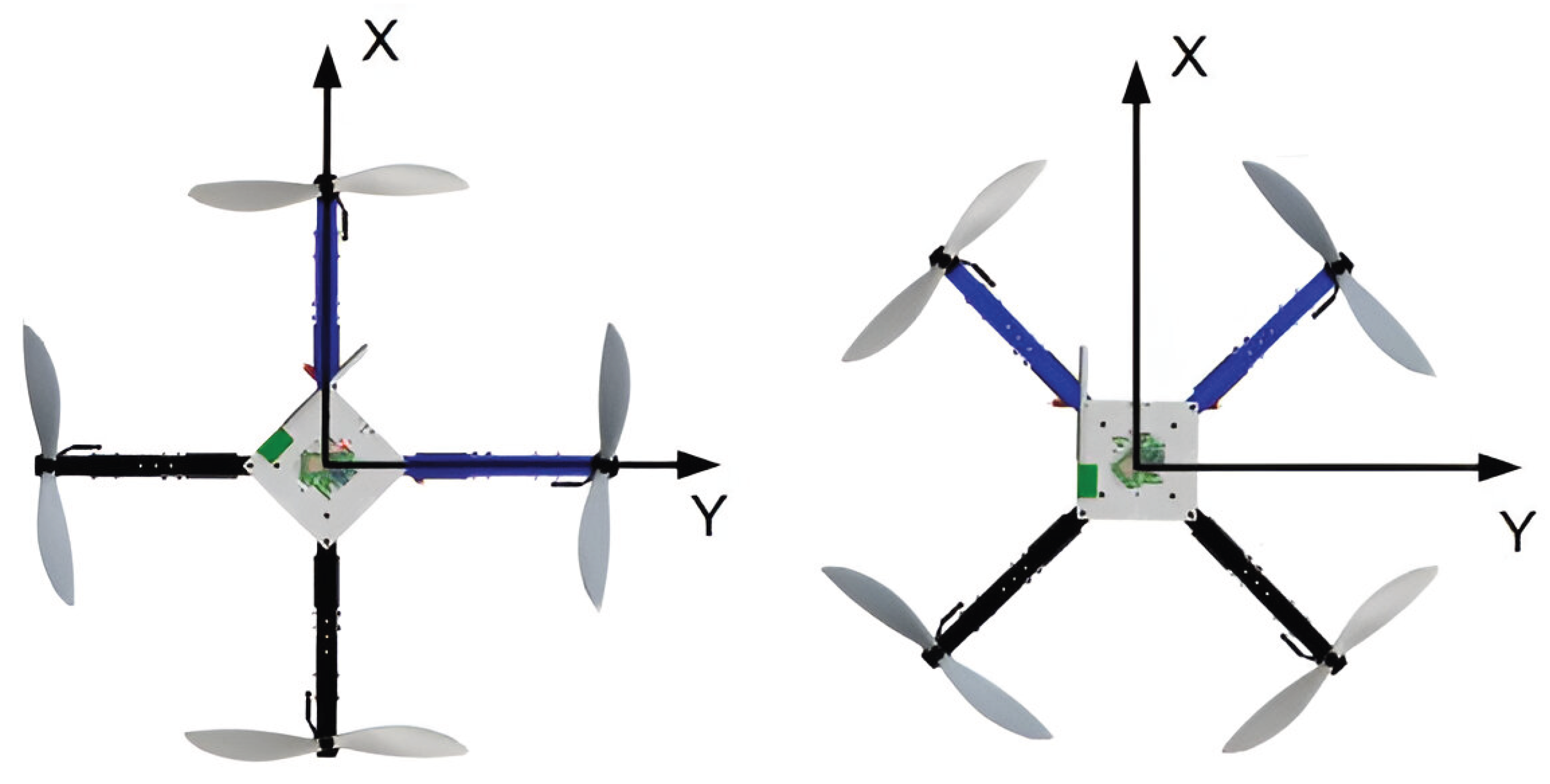
Figure 2.
Quadcopter Rotational Diagram
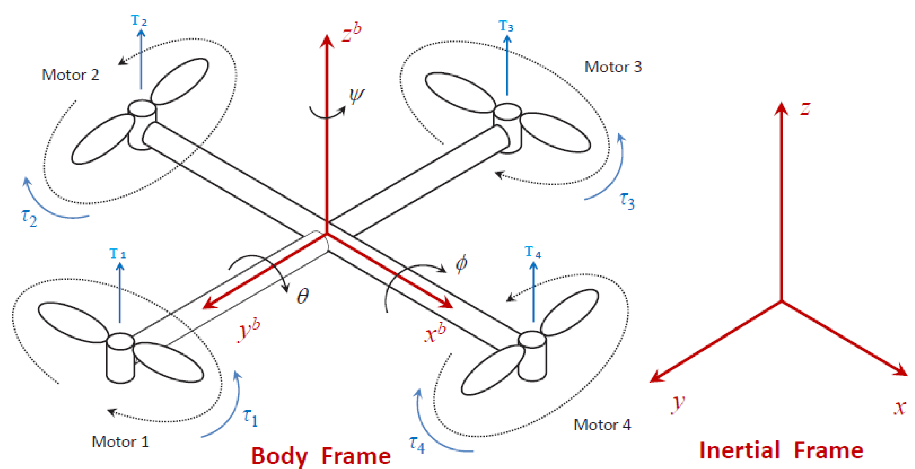
Figure 3.
Block Diagram of the Proposed Controller
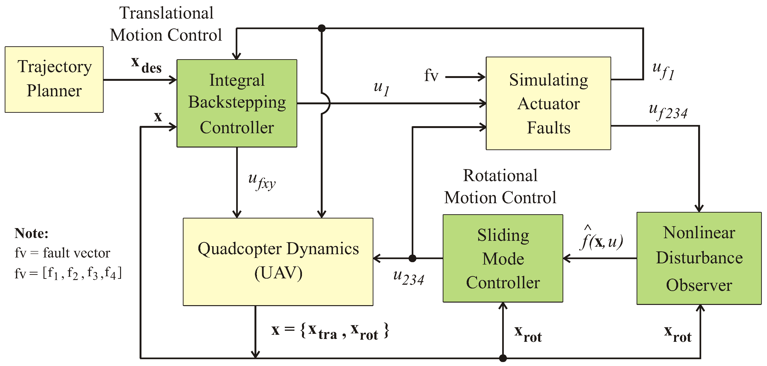
Figure 4.
Block Diagram of Proposed System
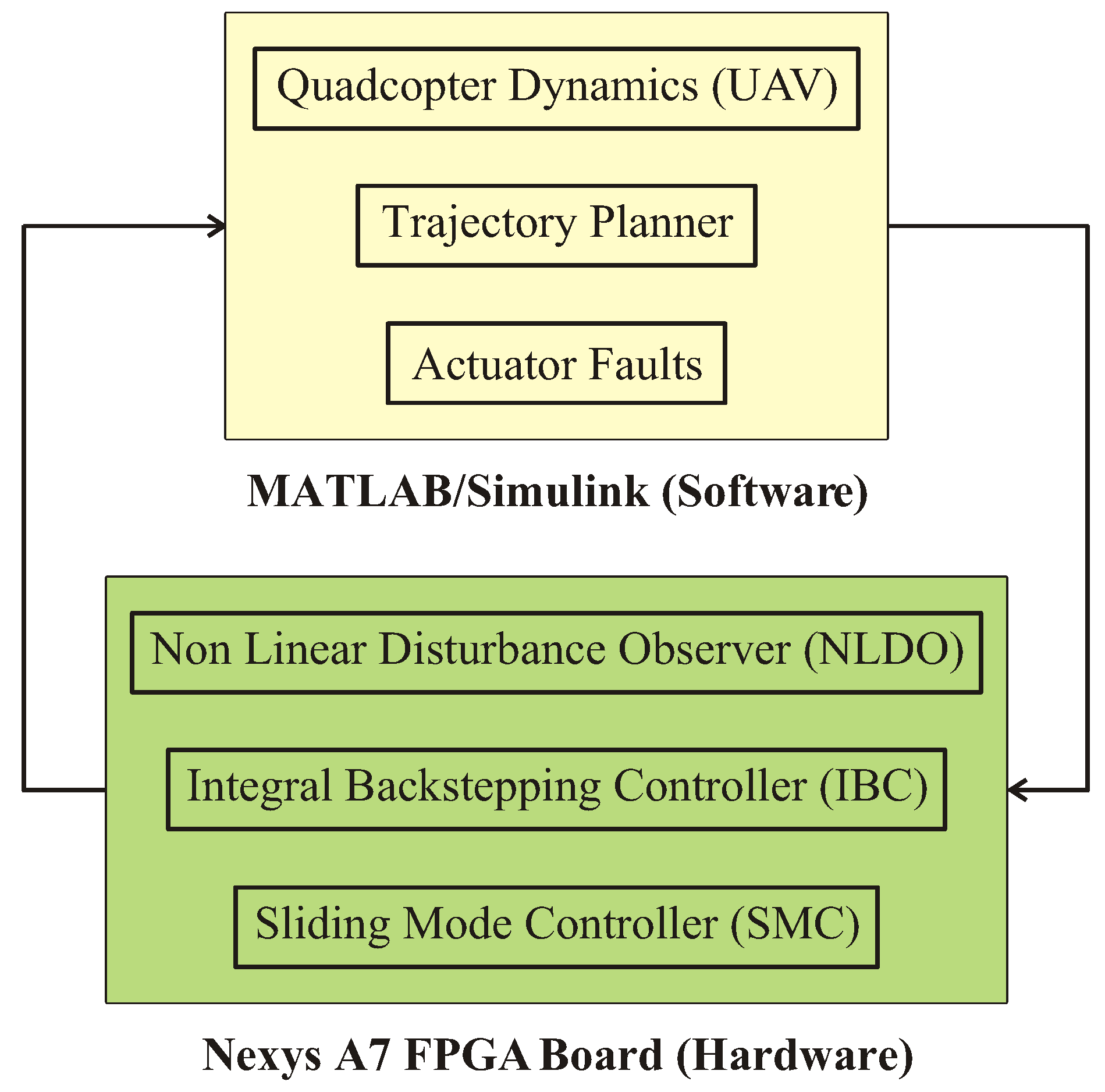
Figure 5.
Hardware in the Loop Testing Experimental Setup
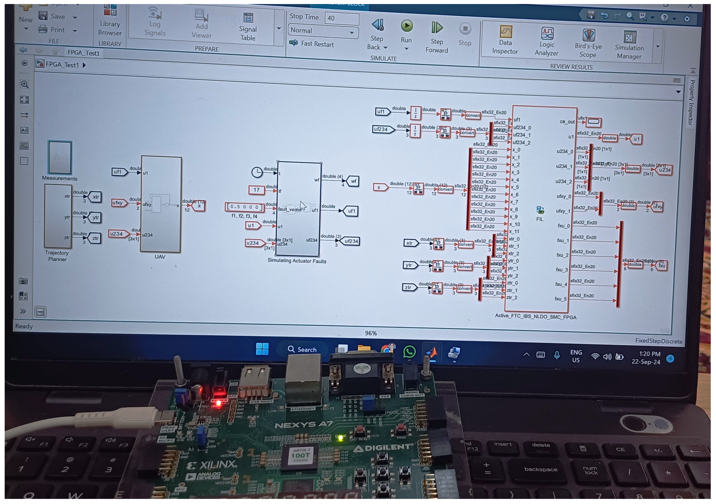
Figure 6.
Desired Trajectory of the Quadcopter
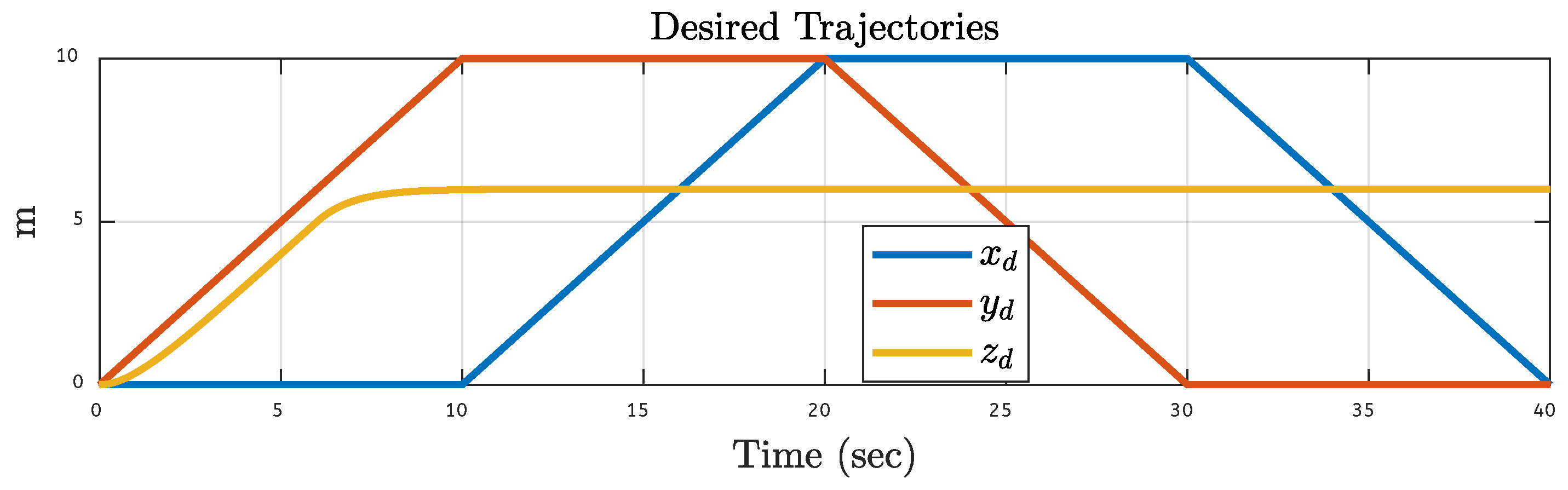
Figure 7.
Actual Trajectories Results After 20% Fault on Motor 1: (a) Simulations Based. (b) FPGA-based.
Figure 7.
Actual Trajectories Results After 20% Fault on Motor 1: (a) Simulations Based. (b) FPGA-based.
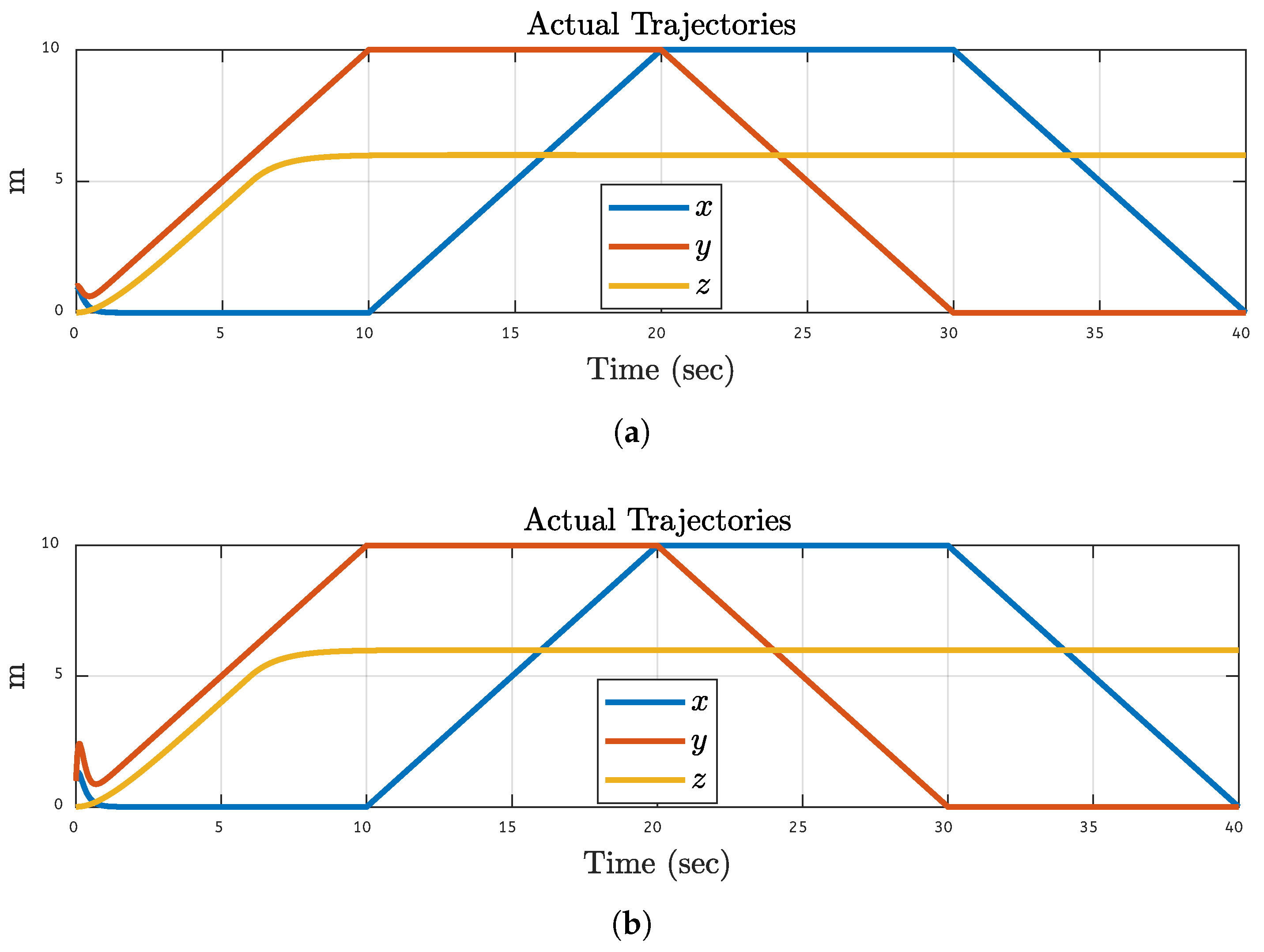
Figure 8.
Actual Trajectories Results After 30% Fault on Motor 2: (a) Simulations Based. (b) FPGA-based.
Figure 8.
Actual Trajectories Results After 30% Fault on Motor 2: (a) Simulations Based. (b) FPGA-based.
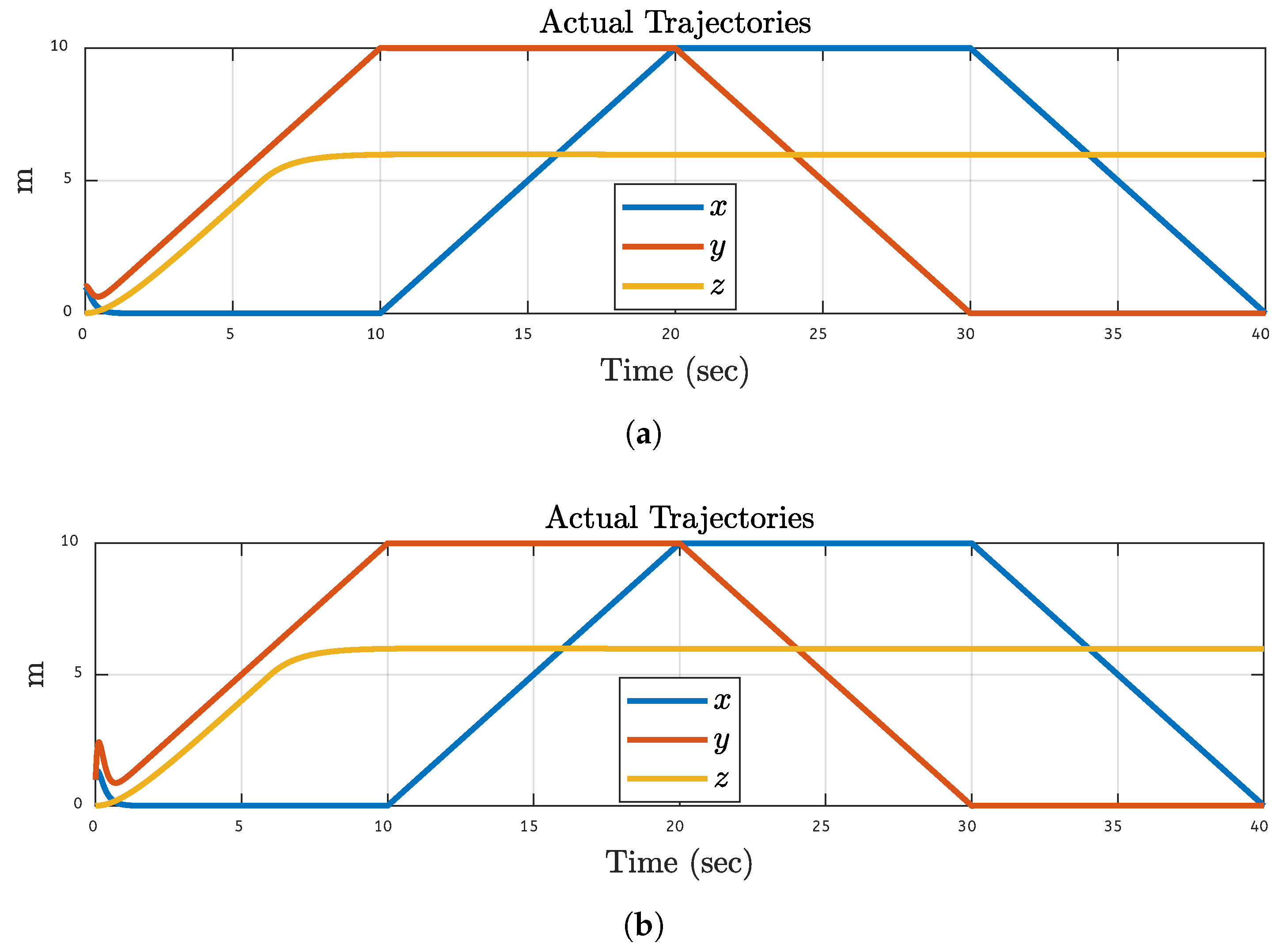
Figure 9.
Actual Trajectories Results After 40% Fault on Motor 3: (a) Simulations Based. (b) FPGA-based.
Figure 9.
Actual Trajectories Results After 40% Fault on Motor 3: (a) Simulations Based. (b) FPGA-based.
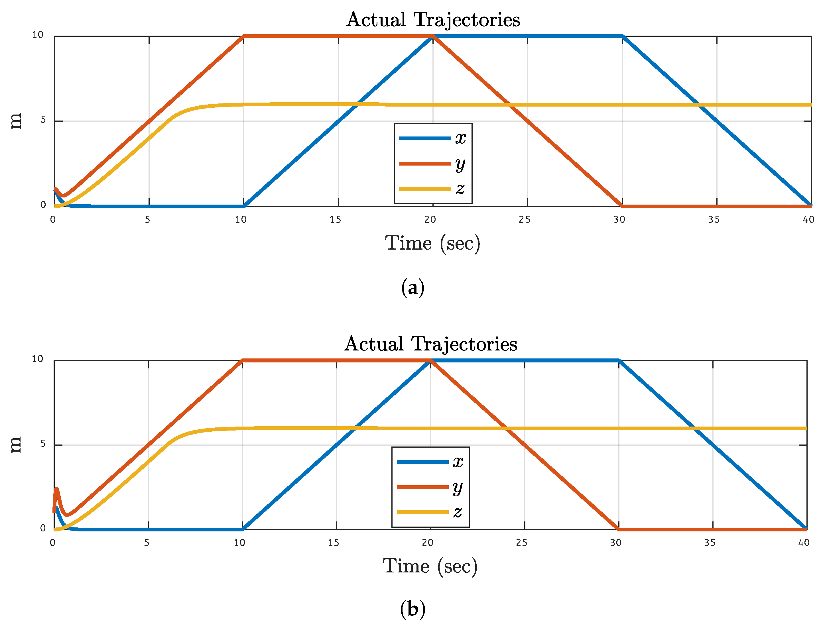
Figure 10.
Actual Trajectories Results After 50% Fault on Motor 4: (a) Simulations Based. (b) FPGA-based.
Figure 10.
Actual Trajectories Results After 50% Fault on Motor 4: (a) Simulations Based. (b) FPGA-based.
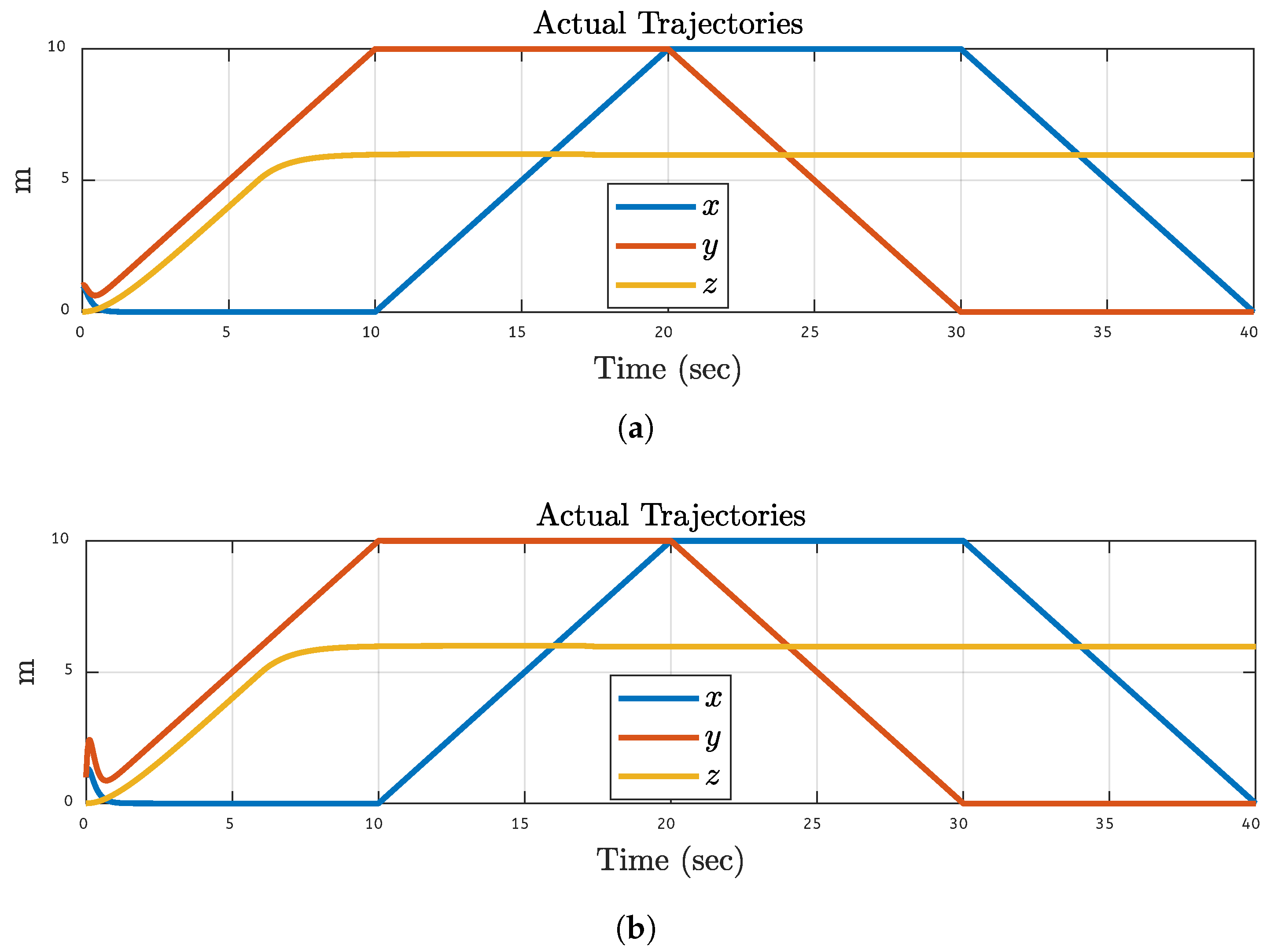
Figure 11.
3D Plane Trajectories Results After 20% Fault on Motor 1: (a) Simulations Based. (b) FPGA-based.
Figure 11.
3D Plane Trajectories Results After 20% Fault on Motor 1: (a) Simulations Based. (b) FPGA-based.
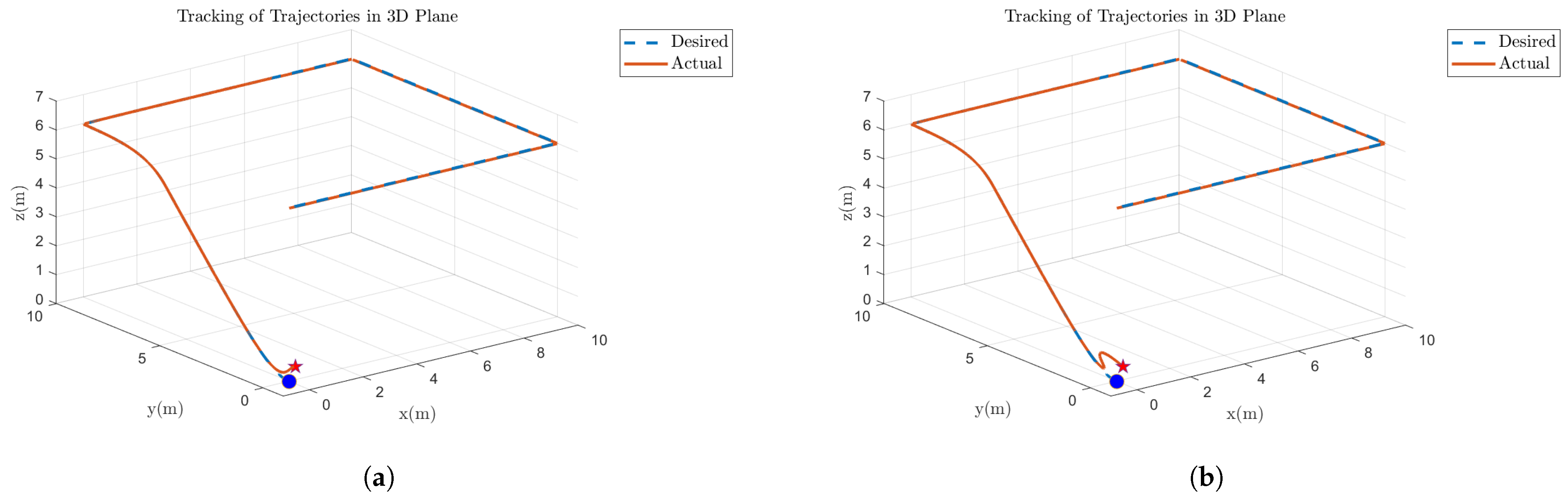
Figure 12.
3D Plane Trajectories Results After 30% Fault on Motor 2: (a) Simulations Based. (b) FPGA-based.
Figure 12.
3D Plane Trajectories Results After 30% Fault on Motor 2: (a) Simulations Based. (b) FPGA-based.
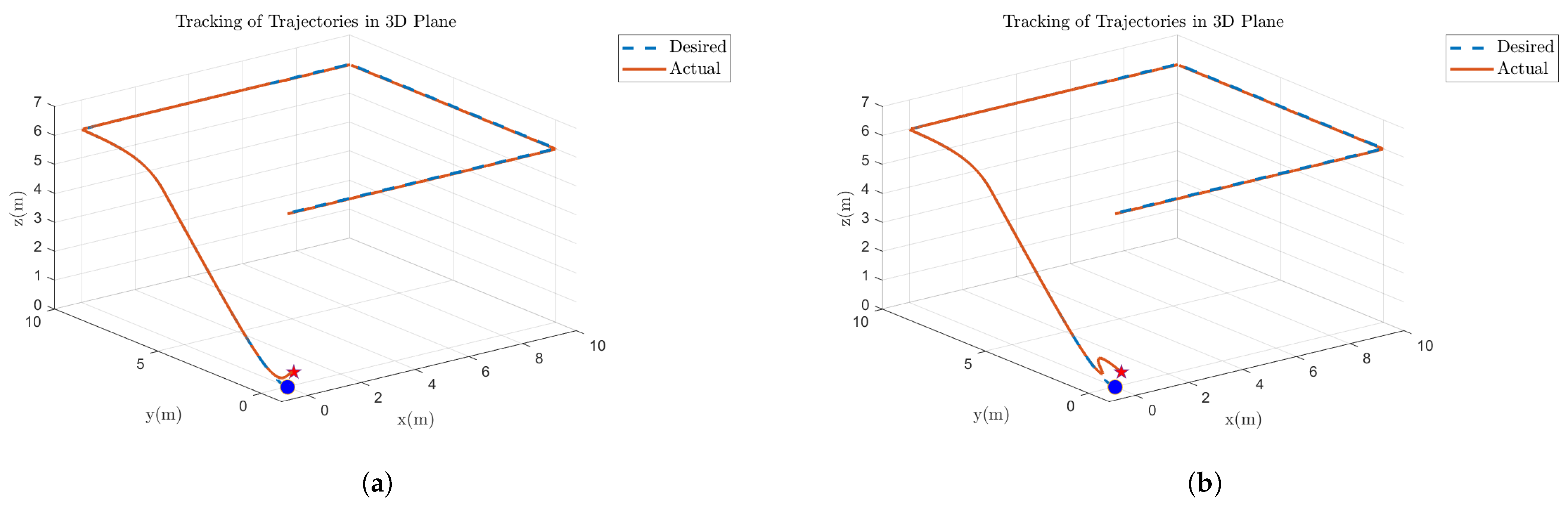
Figure 13.
3D Plane Trajectories Results After 40% Fault on Motor 3: (a) Simulations Based. (b) FPGA-based.
Figure 13.
3D Plane Trajectories Results After 40% Fault on Motor 3: (a) Simulations Based. (b) FPGA-based.
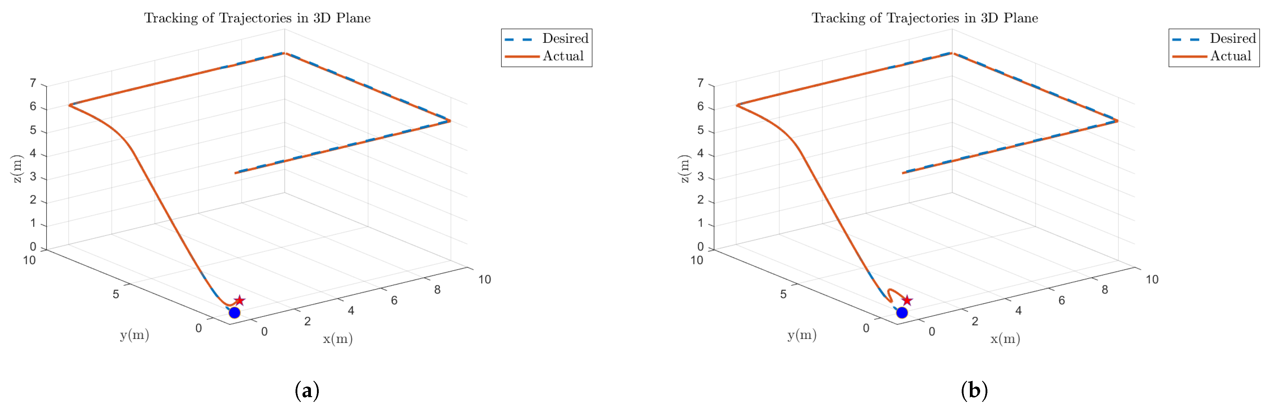
Figure 14.
3D Plane Trajectories Results After 50% Fault on Motor 4: (a) Simulations Based. (b) FPGA-based.
Figure 14.
3D Plane Trajectories Results After 50% Fault on Motor 4: (a) Simulations Based. (b) FPGA-based.
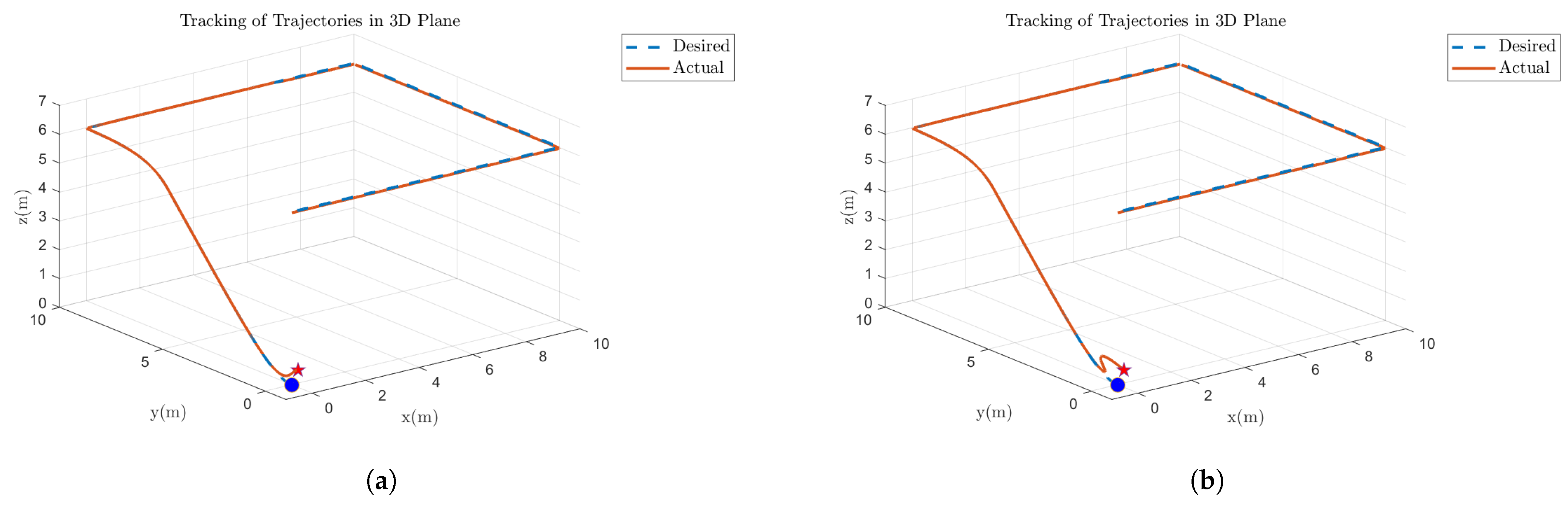
Figure 15.
System dynamics After 20% Fault on Motor 1: (a) Simulations Based. (b) FPGA-based.
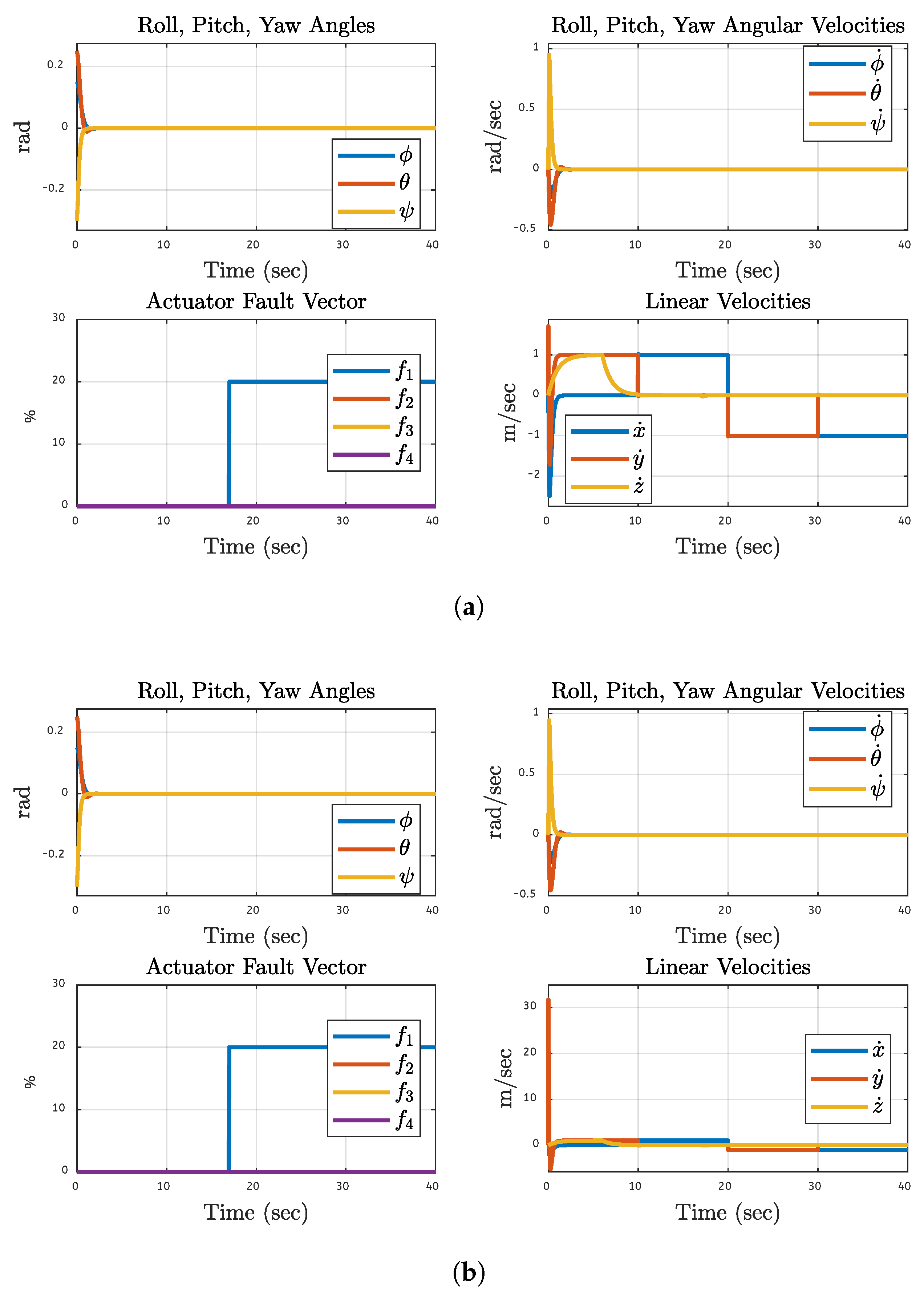
Figure 16.
System dynamics After 30% Fault on Motor 2: (a) Simulations Based. (b) FPGA-based.
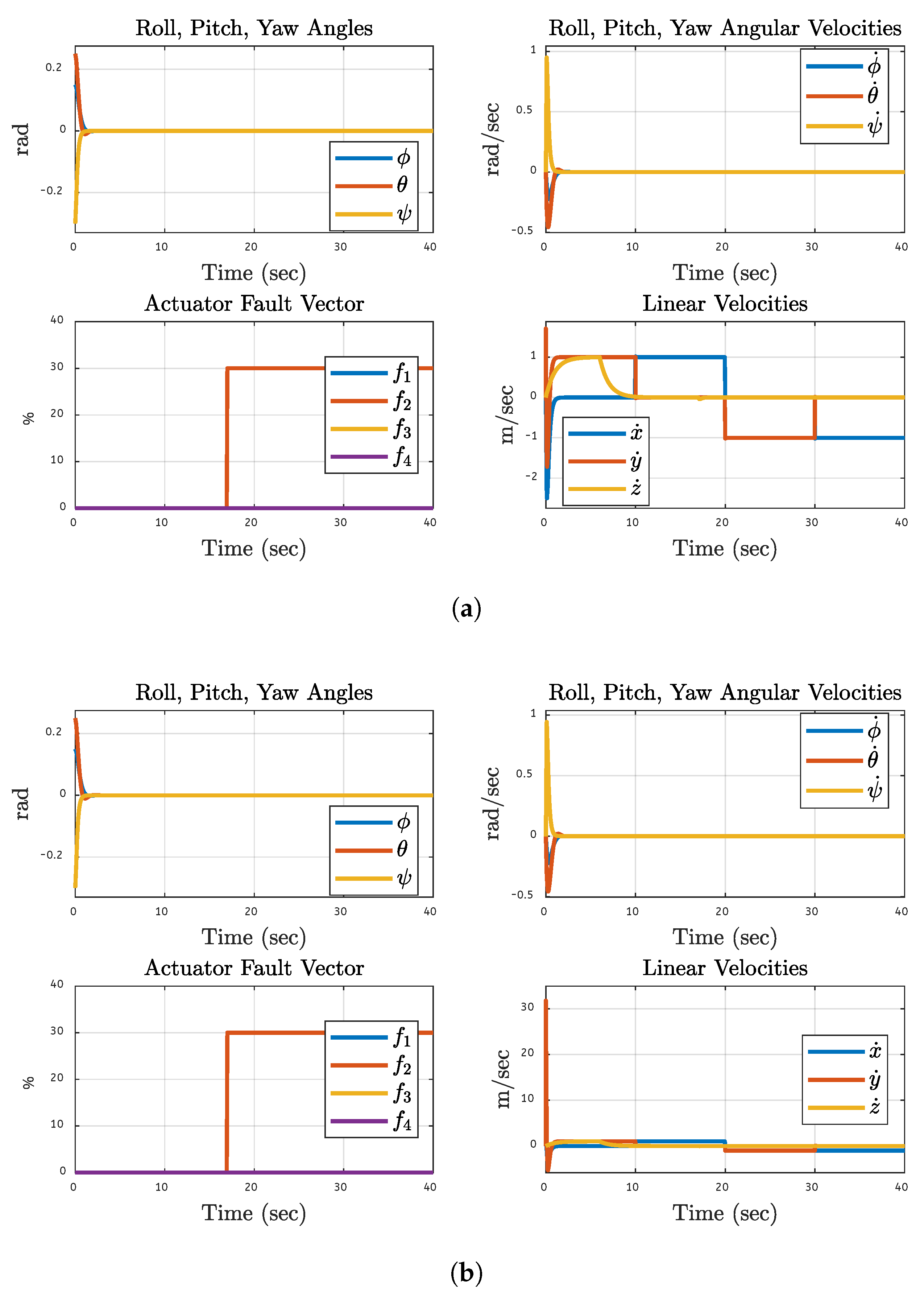
Figure 17.
System dynamics After 40% Fault on Motor 3: (a) Simulations Based. (b) FPGA-based.
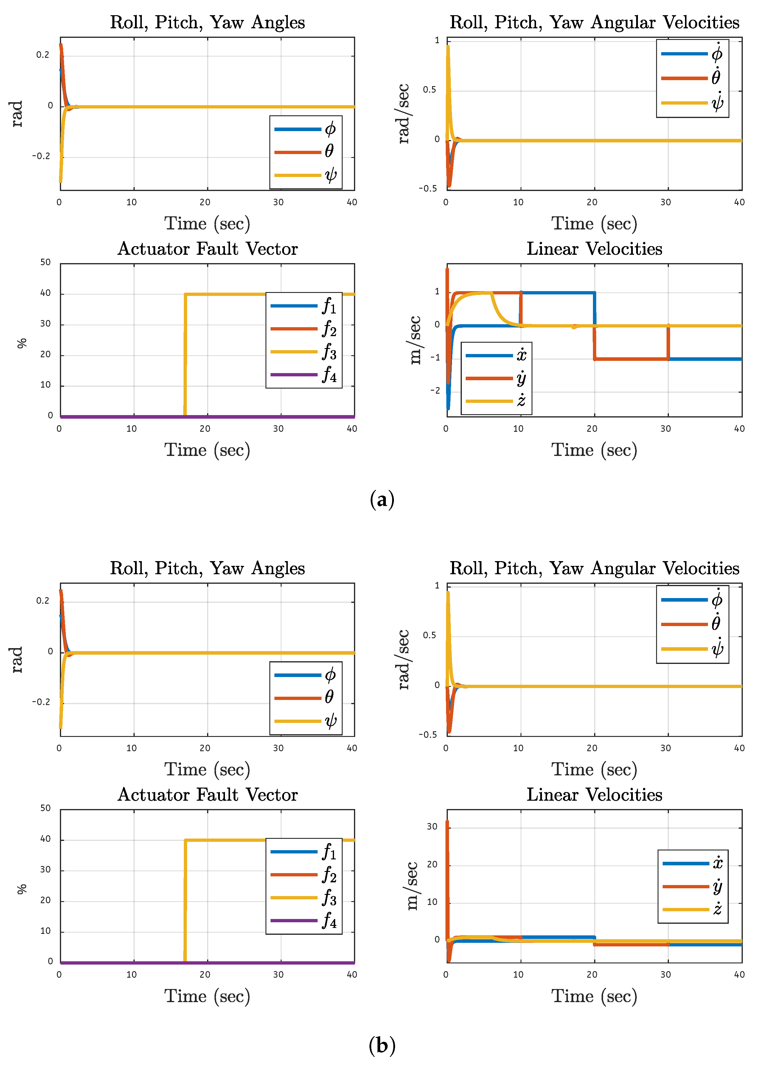
Figure 18.
System dynamics After 50% Fault on Motor 4: (a) Simulations Based. (b) FPGA-based.
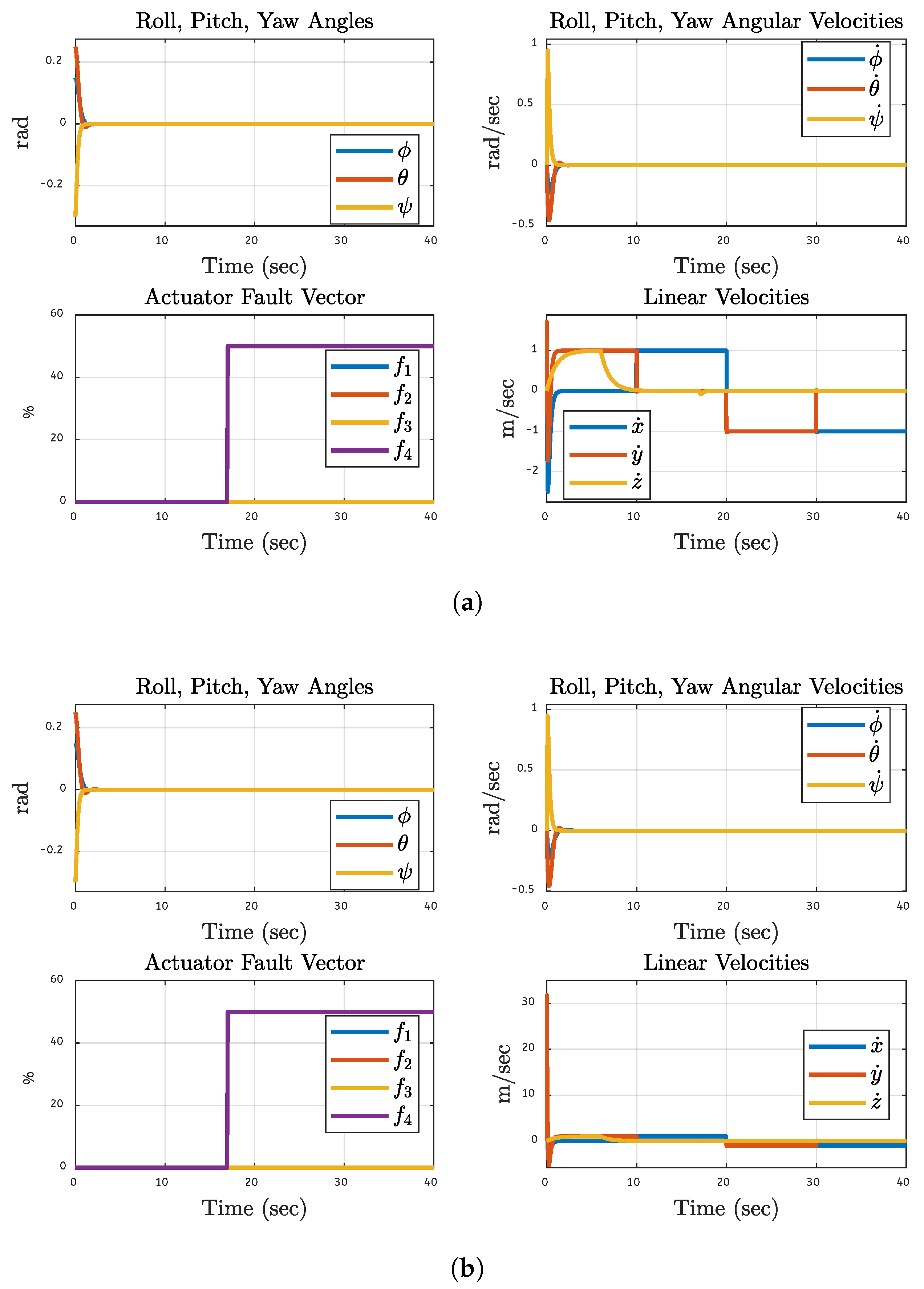
Figure 19.
System Performance Metrics After 20% Fault on Motor 1: (a) Simulations Based. (b) FPGA-based.
Figure 19.
System Performance Metrics After 20% Fault on Motor 1: (a) Simulations Based. (b) FPGA-based.
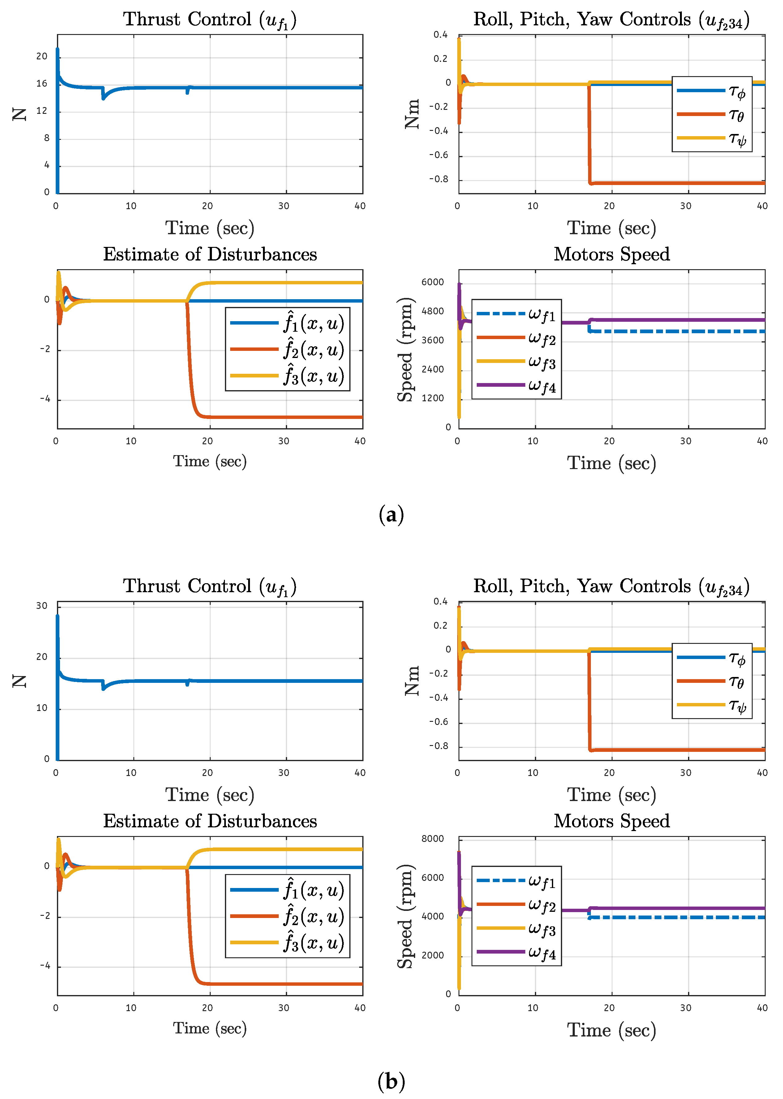
Figure 20.
System Performance Metrics After 30% Fault on Motor 2: (a) Simulations Based. (b) FPGA-based.
Figure 20.
System Performance Metrics After 30% Fault on Motor 2: (a) Simulations Based. (b) FPGA-based.
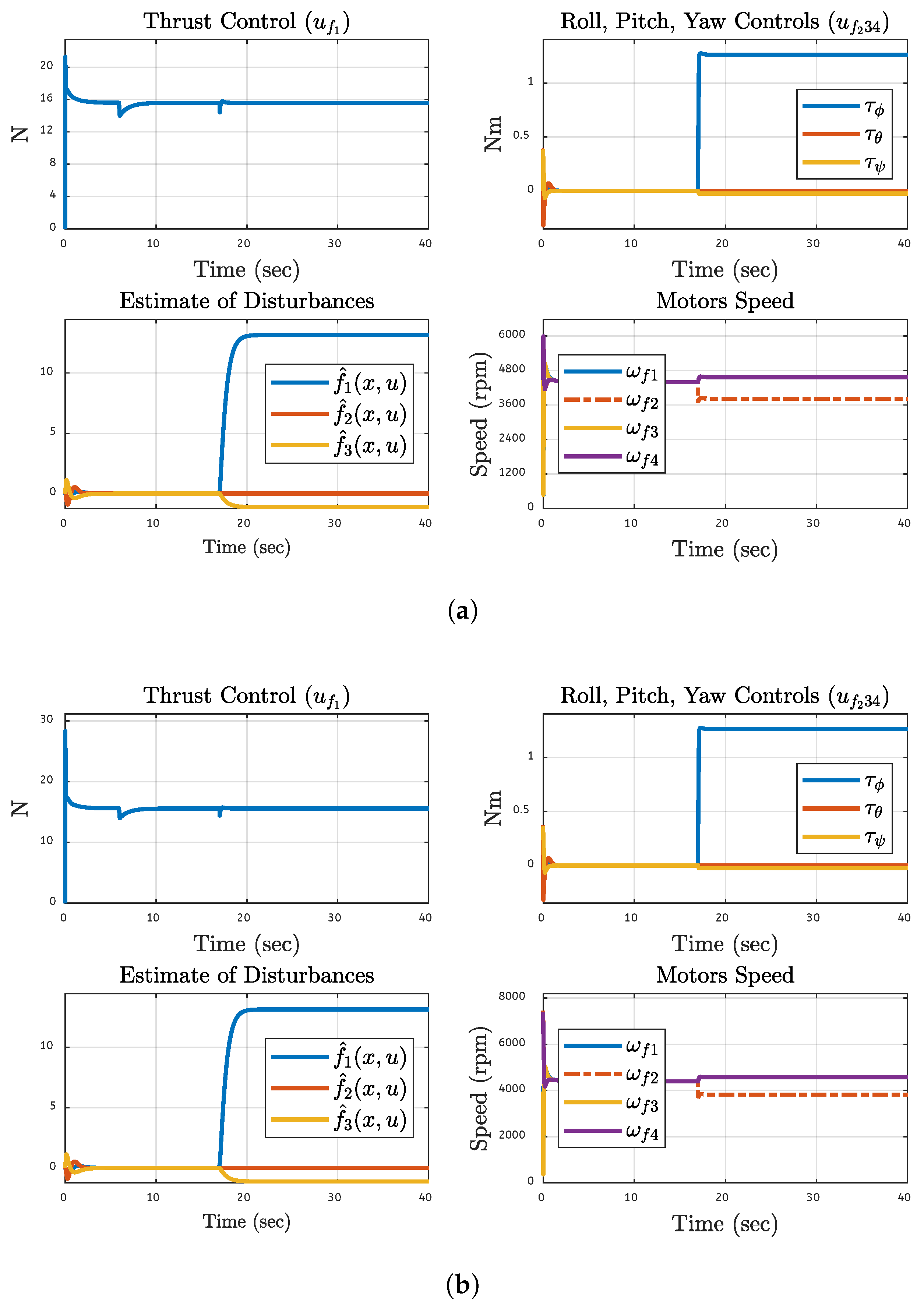
Figure 21.
System Performance Metrics After 40% Fault on Motor 3: (a) Simulations Based. (b) FPGA-based.
Figure 21.
System Performance Metrics After 40% Fault on Motor 3: (a) Simulations Based. (b) FPGA-based.
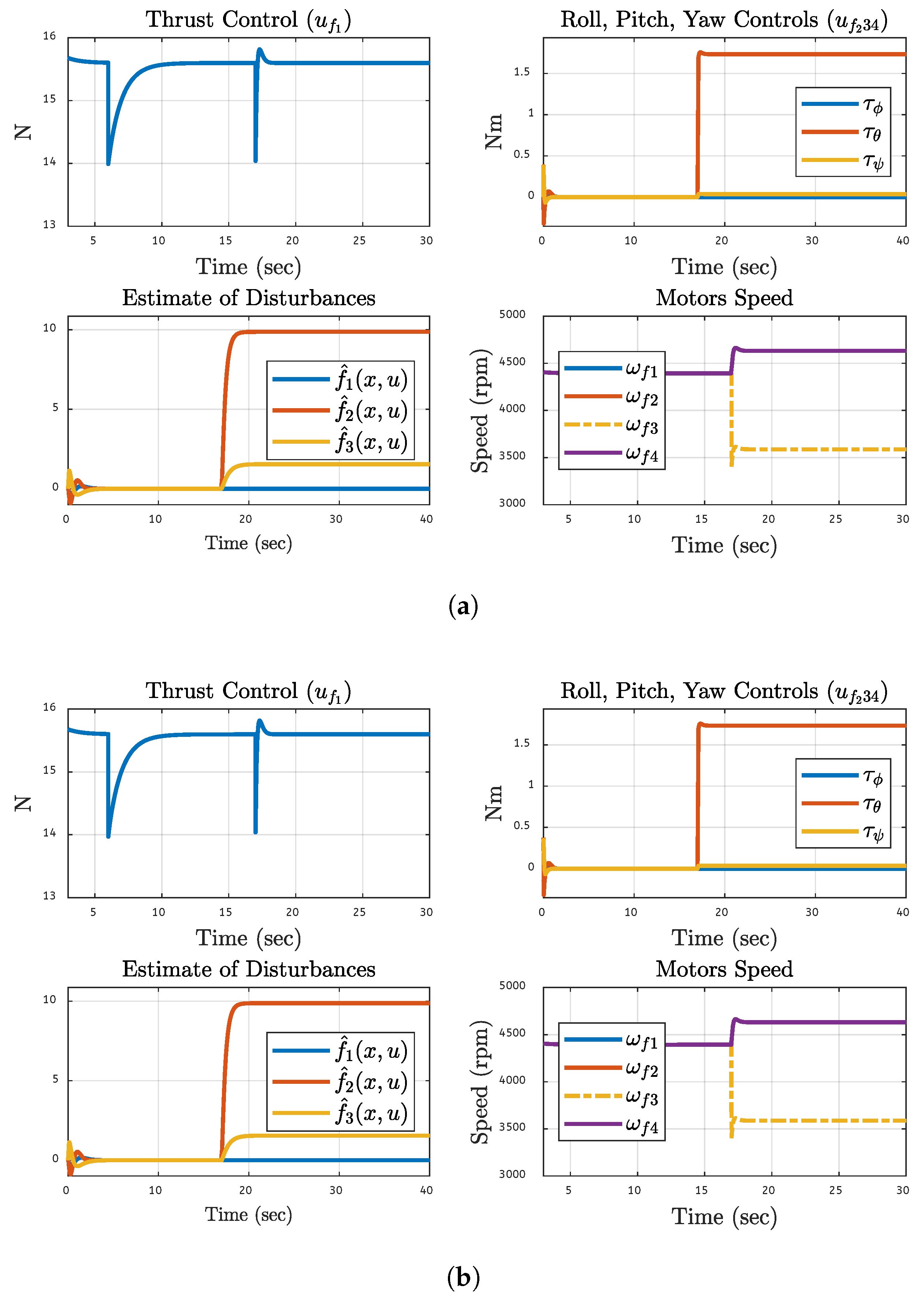
Figure 22.
System Performance Metrics After 50% Fault on Motor 4: (a) Simulations Based. (b) FPGA-based.
Figure 22.
System Performance Metrics After 50% Fault on Motor 4: (a) Simulations Based. (b) FPGA-based.
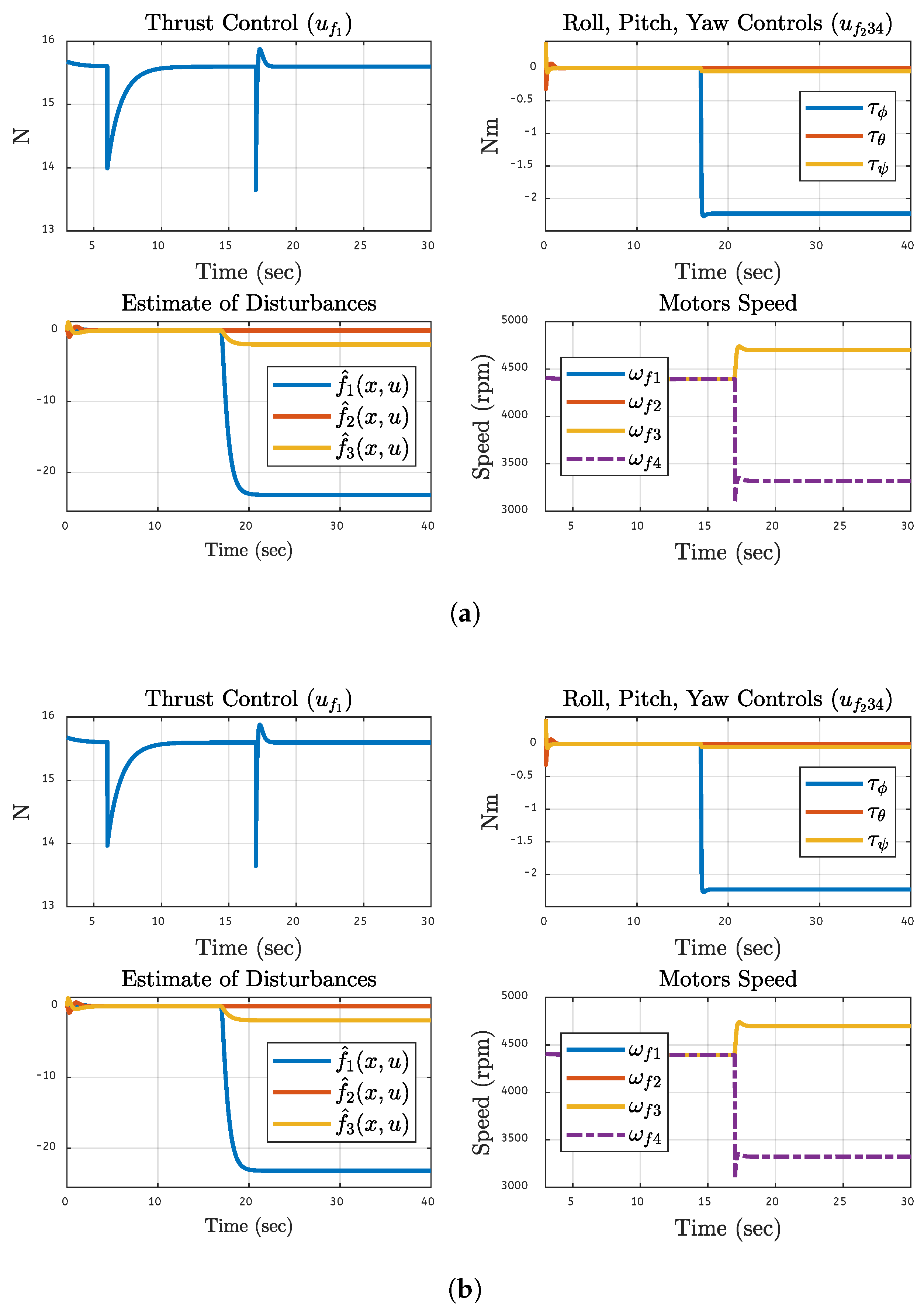

Table 1.
Related Work Summary.
| Reference | Proposed Control System | Results | Limitations |
|---|---|---|---|
| [22] | Sliding mode control with dynamic control allocation | Results showed the effectiveness in maintaining flight stability and performance in the event of motor failure | Complexity of implementing the control strategy in real-time scenarios, limited to simulations only |
| [23] | Novel adaptive control scheme that integrates an L1 adaptive controller with an optimization routine | The system effectively maintained operational resilience and compensates the failure of single propeller failure | Complex real-time implementation and no work if multiple propellers fail. |
| [24] | Finite-time disturbance observer-(FTDO) | The findings showed the effectiveness in multirotor positioning and swing control | Complex techniques to address uncertainties with simulation-based analysis only |
| [25] | Gain-scheduling (GS) controller within the framework of H ∞ synthesis | Results demonstrated robust performance under multiple critical actuator faults | Unsuitable for systems with excessive actuators, such as hexacopters |
| [26] | RBF neural network with SMC method | Efficient in managing UAVs when an accelerometer, gyroscope, or actuator malfunctions | No comprehensive fault tolerance; No HIL testing. |
| [27] | Integral back-stepping control with disturbance rejection for translational motion | Stable translational control with effective disturbance rejection | No HIL testing and no rotational fault tolerance. |
| [28] | Adaptive Fault-Tolerant H-Infinity Output Feedback Control | The Lead-Wing close formation flight simulation results validate the practicality of the model | lack of FPGA testing and limited to small-magnitude faults |
| [29] | The study employs a Simple Adaptive Control with Anti-Windup Compensator | Actuator saturation successfully countered, such that stable control outputs result, even in the presence of actuator faults | Simulation performed in a controlled environment, extreme parameter uncertainties and actuator faults can challenge its validity |
| [30] | SMC to address issues related to a rear servo’s stuck fault in a tilt trirotor | UAV maintains stable attitudes even when external disturbances are introduced | The control scheme is effective, it may still be sensitive to minor disturbances only |
| [31] | Gated recurrent unit (GRU) neural network within a gain-scheduled framework | Three attitude angles effectiveness loss 10%, 30%, and 10% | The efficiency of the model is heavily depends on the quality of the training data. |
| [32] | AESO-based geometric fault-tolerant control (AESOGFTC) | Attitude error to converge to zero in the first 10 seconds, with little shift for actuator faults | The lumped disturbance’s upper bound was unknown when the controllers were constructed |
| This work | Integrates NLDO-based SMC with IBSC as FTC for quadcopter motion control | The proposed control model can tolerate 50% fault in any single motor of the quadcopter | Real-time validation using FPGA, Hybrid control system |
Table 2.
Quadcopter’s Physical Parameters and Values
| Parameters | Values |
|---|---|
| Mass (m) | |
| Length (l) | |
| Gravity (g) | |
| Propeller Chord (c) | |
| Propeller Radius () | |
| Propeller DC () | |
| Arm Length (l) | |
| Thrust Factor (b) | |
| Drag Factor (d) | |
| Air density () | |
| Span Area (A) | |
| Rotor Inertia () | |
| Max. Rotor Speed () | |
| Inertial Moment () | |
| Inertial Moment () | |
| Inertial Moment () | |
| Translational DC (, ) | |
| Translational DC () | |
| Rotational DC. (, ) | |
| Rotational DC () |
DC: Drag Coefficient.
Table 3.
Factors and their Values used in Modeling
| Parameter | Value |
|---|---|
| Translational Gain | , |
| , | |
| , | |
| Rotational Gain | , |
| , | |
| , | |
| Starting Point | , , |
| , , | |
| Tuning Paramater | , , |
Table 4.
Numerical Results
| Simulation Based Numerical Results | |||||||||
|---|---|---|---|---|---|---|---|---|---|
| Motor | Fault % | ||||||||
| Motor 1 | 20% | 0.885 | 1.168 | 4.10E-23 | 6.16E-23 | 3.77E-40 | 121.88 | 16196.7 | 19.272 |
| Motor 2 | 30% | 1.331 | 1.234 | 3.39E-23 | 6.04E-23 | 3.78E-40 | 318.32 | 25196.7 | 29.690 |
| Motor 3 | 40% | 1.778 | 1.273 | 4.10E-23 | 5.89E-23 | 3.76E-40 | 257.30 | 34942.9 | 40.686 |
| Motor 4 | 50% | 2.228 | 1.295 | 5.19E-08 | 6.14E-23 | 3.79E-40 | 560.85 | 45596.3 | 52.311 |
| FPGA Hardware Based Numerical Results | |||||||||
| Motor | Fault % | ||||||||
| Motor 1 | 20% | 0.885 | 1.168 | 4.10E-23 | 6.16E-23 | 3.77E-40 | 121.88 | 16196.7 | 19.272 |
| Motor 2 | 30% | 1.331 | 1.234 | 3.39E-23 | 6.04E-23 | 3.78E-40 | 318.32 | 25196.7 | 29.690 |
| Motor 3 | 40% | 1.778 | 1.273 | 4.10E-23 | 5.89E-23 | 3.76E-40 | 257.30 | 34942.9 | 40.686 |
| Motor 4 | 50% | 2.228 | 1.295 | 5.19E-08 | 6.14E-23 | 3.79E-40 | 560.85 | 45596.3 | 52.311 |
Disclaimer/Publisher’s Note: The statements, opinions and data contained in all publications are solely those of the individual author(s) and contributor(s) and not of MDPI and/or the editor(s). MDPI and/or the editor(s) disclaim responsibility for any injury to people or property resulting from any ideas, methods, instructions or products referred to in the content. |
© 2025 by the authors. Licensee MDPI, Basel, Switzerland. This article is an open access article distributed under the terms and conditions of the Creative Commons Attribution (CC BY) license (http://creativecommons.org/licenses/by/4.0/).
Copyright: This open access article is published under a Creative Commons CC BY 4.0 license, which permit the free download, distribution, and reuse, provided that the author and preprint are cited in any reuse.


